Optimization of Hydraulic Fracturing Fluid System in a Sand Oil Reservoir in Southwest of Iran Reza Masoomi #1 , Iniko Bassey #2 , Dolgow S.V. #3 , Fatemeh Shademanfard 4 , Innocent Ugbong 5 # Department of Petroleum Engineering, Kuban State University of Technology, Krasnodar, Russia 4 Department of Petroleum Engineering, Marvdasht Branch, Islamic Azad University, Marvdast, Iran 5 Department of Cadastre and Geo-Engineering, Kuban State University of Technology, Krasnodar, Russia 1 [email protected]2 [email protected]3 [email protected]4 [email protected]5 [email protected]Abstract- Fracturing fluid is one of the most important components of a hydraulic fracturing operation. Currently a lot of fluids are available for hydraulic fracturing. In order to selecting the most appropriate fracturing fluid for oil and gas wells with special characteristics, should be well understood fluid properties and should be informed about how changes in fluid properties to achieve the desired results. The aim of this study is optimization of viscosity and gel concentration in water base and foam base fluids which are used in hydraulic fracturing process in a sand oil reservoir in southwest of Iran. For this purpose various scenarios have been designed for various kinds of water base fluids and foam base fluids. Then the cumulative oil production has been estimated versus time and fracture half length. In addition the final required fracturing fluid and proppant have been determined for hydraulic fracturing in studied reservoir. Also in this study increasing the cumulative oil recovery in fractured and Non-fractured wells in a sand oil reservoir in southwest of Iran have been investigated. Keywords- Hydraulic fracturing, Water base fluid, Foam base fluid, Viscosity, Gel concentration I. Introduction Currently a lot of fluids are available for hydraulic fracturing. In order to selecting the most appropriate fracturing fluid for oil and gas wells with special characteristics, should be well understood fluid properties and should be informed about how changes in fluid properties to achieve the desired results. Fracturing fluid is one of the most important components of a hydraulic fracturing operation. Its most important effects are opening the fracture, crack extension and proppant transferring into the fracture channels. After placement of proppants in the fracture and being trapped by the closure stresses, fracturing fluid and its additives are diluted. Then fracturing fluid are spewed out of the fracture channels in order to making flow through the reservoir to the fracture channels. Therefore hydrocarbons can easily enter the fracture channels. [1] Pilehvari and Clark (1985) used two slot-flow rheometers, one with a rough and one with a smooth surface to study slip flow in hydraulic fracturing fluids. Each slot was equipped with a set of flush-mount pressure transducers to measure pressure drop and a thin-film anemometer probe to measure pressure drop and a thin- film anemometer probe to measure heat transfer at the wall. Experiments with crosslinked gels showed that rough surfaces inhibited wall slippage while smooth surfaces promoted it. Both batch and continuous crosslinked gels showed significantly different shear stress measured with the two rheometers for the same shear rates, a clear indication of wall slip. For batch crosslinked gels, this was confirmed with the results of hot-film anemometry. [2] Powel and McCabe (1997) developed a new, borate-crosslinked hydraulic fracturing fluid system. This new, optimized fluid system provided higher viscosity with lower gelling-agent concentrations compared to conventional, borate-crosslinked fluids. Application of the optimized low-gel borate (OLGB) fluid system at low temperatures was discussed. Viscosity, proppant transport and fluid-loss data of the OLGB fluid system were compared to conventional, borate-crosslinked fracturing fluids. Treatment designs were also presented in their work. [3] Tayal and Kelly (1997) used steady shear rheometry to elicit fundamental information on the capabilities and limitations of enzymes. The effect of commercial and new thermostable enzymes on polymer viscosity was investigated in terms of process variables such as temperature of hydrolysis, pH of solution and enzyme concentration. The commercial enzyme was most effective in degrading the guar at slightly acidic conditions Reza Masoomi et al. / International Journal of Engineering and Technology (IJET) ISSN : 0975-4024 Vol 7 No 5 Oct-Nov 2015 1693
Transcript
Optimization of Hydraulic Fracturing Fluid System in a Sand Oil Reservoir in
#Department of Petroleum Engineering, Kuban State University of Technology, Krasnodar, Russia 4Department of Petroleum Engineering, Marvdasht Branch, Islamic Azad University, Marvdast, Iran
5Department of Cadastre and Geo-Engineering, Kuban State University of Technology, Krasnodar, Russia 1 [email protected]
Abstract- Fracturing fluid is one of the most important components of a hydraulic fracturing operation. Currently a lot of fluids are available for hydraulic fracturing. In order to selecting the most appropriate fracturing fluid for oil and gas wells with special characteristics, should be well understood fluid properties and should be informed about how changes in fluid properties to achieve the desired results.
The aim of this study is optimization of viscosity and gel concentration in water base and foam base fluids which are used in hydraulic fracturing process in a sand oil reservoir in southwest of Iran. For this purpose various scenarios have been designed for various kinds of water base fluids and foam base fluids. Then the cumulative oil production has been estimated versus time and fracture half length. In addition the final required fracturing fluid and proppant have been determined for hydraulic fracturing in studied reservoir.
Also in this study increasing the cumulative oil recovery in fractured and Non-fractured wells in a sand oil reservoir in southwest of Iran have been investigated.
Keywords- Hydraulic fracturing, Water base fluid, Foam base fluid, Viscosity, Gel concentration
I. Introduction
Currently a lot of fluids are available for hydraulic fracturing. In order to selecting the most appropriate fracturing fluid for oil and gas wells with special characteristics, should be well understood fluid properties and should be informed about how changes in fluid properties to achieve the desired results. Fracturing fluid is one of the most important components of a hydraulic fracturing operation. Its most important effects are opening the fracture, crack extension and proppant transferring into the fracture channels. After placement of proppants in the fracture and being trapped by the closure stresses, fracturing fluid and its additives are diluted. Then fracturing fluid are spewed out of the fracture channels in order to making flow through the reservoir to the fracture channels. Therefore hydrocarbons can easily enter the fracture channels. [1]
Pilehvari and Clark (1985) used two slot-flow rheometers, one with a rough and one with a smooth surface to study slip flow in hydraulic fracturing fluids. Each slot was equipped with a set of flush-mount pressure transducers to measure pressure drop and a thin-film anemometer probe to measure pressure drop and a thin-film anemometer probe to measure heat transfer at the wall. Experiments with crosslinked gels showed that rough surfaces inhibited wall slippage while smooth surfaces promoted it. Both batch and continuous crosslinked gels showed significantly different shear stress measured with the two rheometers for the same shear rates, a clear indication of wall slip. For batch crosslinked gels, this was confirmed with the results of hot-film anemometry. [2]
Powel and McCabe (1997) developed a new, borate-crosslinked hydraulic fracturing fluid system. This new, optimized fluid system provided higher viscosity with lower gelling-agent concentrations compared to conventional, borate-crosslinked fluids. Application of the optimized low-gel borate (OLGB) fluid system at low temperatures was discussed. Viscosity, proppant transport and fluid-loss data of the OLGB fluid system were compared to conventional, borate-crosslinked fracturing fluids. Treatment designs were also presented in their work. [3]
Tayal and Kelly (1997) used steady shear rheometry to elicit fundamental information on the capabilities and limitations of enzymes. The effect of commercial and new thermostable enzymes on polymer viscosity was investigated in terms of process variables such as temperature of hydrolysis, pH of solution and enzyme concentration. The commercial enzyme was most effective in degrading the guar at slightly acidic conditions
Reza Masoomi et al. / International Journal of Engineering and Technology (IJET)
ISSN : 0975-4024 Vol 7 No 5 Oct-Nov 2015 1693
and up to 60°C. Above 60°C, the extent of hydrolysis of guar solutions decreased. With increasing temperature, enzymatic activity increased but enzyme stability decreased and this balance was critical in determining the extent of viscosity reduction. [4]
Putzig and Clair (2007) developed a new delay agent which had hybrid functionality versus previously-reported materials. It delayed viscosity development in fracturing fluids based on guar derivatives crosslinked with a variety of common zirconate and titanate crosslinkers under a wide range of PH. The viscosity development could be optimized by adjusting the concentrations of polymer, crosslinker, and delay additive to give the desired profile for a given hydraulic fracturing application. [5]
McAndrew and Fan (2014) discussed arguments for the use of fracturing foam base fluids beyond the under-pressured, dry gas reservoirs where they are already favored, using a model developed at the University of Texas at Austin. The simulation study used reservoir conditions based on available information for the Utica, which was chosen because it is a liquid-rich shale of current interest. [6]
II. Investigating of Hydraulic Fracturing in Oil Reservoir “Z” in Southwest of Iran
A large number of Iran’s hydrocarbon reservoir with oil production dating back of several years, are now in a declining period of their production. This has prompted the authorities and petroleum engineers to use effective methods for increasing production. In addition some reservoirs have the good initial oil inplace but they have not a desirable flow capacity. That is why the well stimulation operations seem to be necessary for increasing the permeability. A. Studied field characteristics
Studied field is an asymmetric anticline with a length of 11 km and width of 3 km. This is a single-porosity sandstone field with 16 oil layers. Its oil is a relatively heavy with API grade of 25. Gas-Oil ratio in this reservoir has estimated at 700 scf/STB and oil formation volume factor (FVF) is about 1.4 Rbbl/STB. This is a newly explored oil field and now is in a stage of development.
Studied field is in undersaturation conditions and there is no gas cap in studied reservoir. Its reservoir rock is oil wet. Studied field has 16 oil layers with thickness of totally 196 m or 643 feet. The average pressure of studied reservoir is about 240.5 atm (3535 psia). The datum depth of calculations is about 7100 feet in this reservoir. Oil-Water contact in this reservoir has estimated at 2164.7 m (7453.1 ft) and Gas-Oil contact is estimated about 526 m (1725 ft). The datum depth for aquifer calculations has estimated at 2286.6 m (7500 ft) in this reservoir. A summary of the geology and fluid properties of the studied field is presented in Table 1.
Table I. Fluid General Characteristics of the Studied Field
Properties Value Properties ValueAPI 25 FVF , RbbL/STB Oil 1.4 Total thickness , ft 642 Oil Viscosity , cp 0.68 GOR , SCF/STB 700 Gas Viscosity , cp 0.021 Rock Compressibility,psi-1 2.8 * 10-6 Reservoir Temperature , ℉ 140 Average Porosity , % 12.5 Bubble Point Pressure , Psia 1995 Average Permeability@ Permx 154.55 Average Reservoir Pressure@ datum depth , Psia 5290 Average Permeability@ Permz 2.1 Oil in Place,STB 3.2*108 Initial Oil Saturation , % 79
III. Scenarios of Optimizing the Hydraulic Fracturing Fluid System
In this study various kinds of water base fluids and foam base fluids have been considered for hydraulic fracturing operation in sand oil reservoir “Z” in southwest of Iran. The aim of this study is optimizing the viscosity and gel concentration in water base fluids and foam base fluids used in hydraulic fracturing. For this purpose initially various scenarios have been designed for various kinds of water base fluids. Then the cumulative oil production and fracture conductivity have been estimated for each scenario. The scenarios which have had the highest productivity index in studied reservoir have been selected as optimal scenario for selection of fracturing fluids. Also the final required volume of water base fluids and proppant have been estimated for hydraulic fracturing process in reservoir “Z” in southwest of Iran. In this study also various scenarios have been designed for various kinds of foam base fluids. Then the cumulative oil recovery and fracture conductivity have been estimated for each scenario. The scenarios which have had the highest productivity index in studied reservoir have been selected as optimal scenario for selection of fracturing fluids. Also the final required volume of foam base fluids and proppant have been estimated for hydraulic fracturing process in reservoir “Z” in southwest of Iran.
Reza Masoomi et al. / International Journal of Engineering and Technology (IJET)
ISSN : 0975-4024 Vol 7 No 5 Oct-Nov 2015 1694
A. Scenarios for water base fluids In this section water base fluids have been investigated as fracturing fluid. For this purpose various kinds of
water base fluids were selected with different rheological properties in terms of viscosity and gel concentration. Then different scenarios have been designed for various kinds of water base fluids for hydraulic fracturing operation in oil reservoir “Z”. Also the cumulative oil production and final required volume of fracturing fluids and proppant have been estimated in each scenario for hydraulic fracturing process applied in oil reservoir “Z”. The scenarios which have had the highest productivity index have been selected as optimal scenario. Also in this study increasing the cumulative oil recovery in fractured and Non-fractured wells in a sand oil reservoir in southwest of Iran have been investigated. 1) Scenario A-1: Water base fluid of 40LB/K HEC W/NO-BREAKER
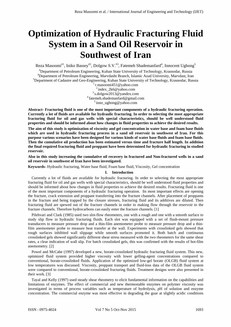
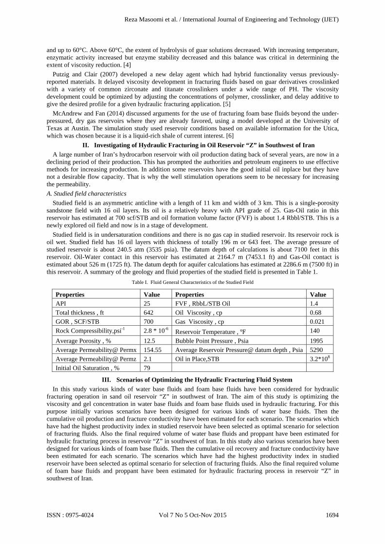
In this scenario water base fluid of 40LB/K HEC W/NO-BREAKER has been considered for hydraulic fracturing process in oil reservoir “Z” in southwest of Iran. Liquid and effective gel concentrations in this water base fluid are 12 and 40.2 lb/mgal respectively. The viscosity of this water base fluid is estimated to be 37 cp. In this scenario the injection rate is 35 bpm and fracture half length is considered about 850 ft. Also proppant used in this scenario is intended to be Ceramic 8/12. The cumulative oil production is predicted 356713 STB with using 40LB/K HEC W/NO-BREAKER fracturing fluid in oil reservoir “Z” for a period of one year. For achieving this oil production volume the final required volume of fracturing fluid is about 51725 gal and 628037 lb of proppant is required. Cumulative oil production versus time and fracture half length is presented in Figures 1 and 2 respectively.
Fig. 1. Cumulative oil production versus time for water base fluid of 40LB/K HEC W/NO-BREAKER
Fig. 2. Cumulative oil production versus fracture half length for water base fluid of 40LB/K HEC W/NO-BREAKER
Reza Masoomi et al. / International Journal of Engineering and Technology (IJET)
ISSN : 0975-4024 Vol 7 No 5 Oct-Nov 2015 1695
2) Scenario A-2: Water base fluid of 64 LB/K HEC w/NO BREAKER In this scenario water base fluid of 64 LB/K HEC w/NO BREAKER has been considered for hydraulic
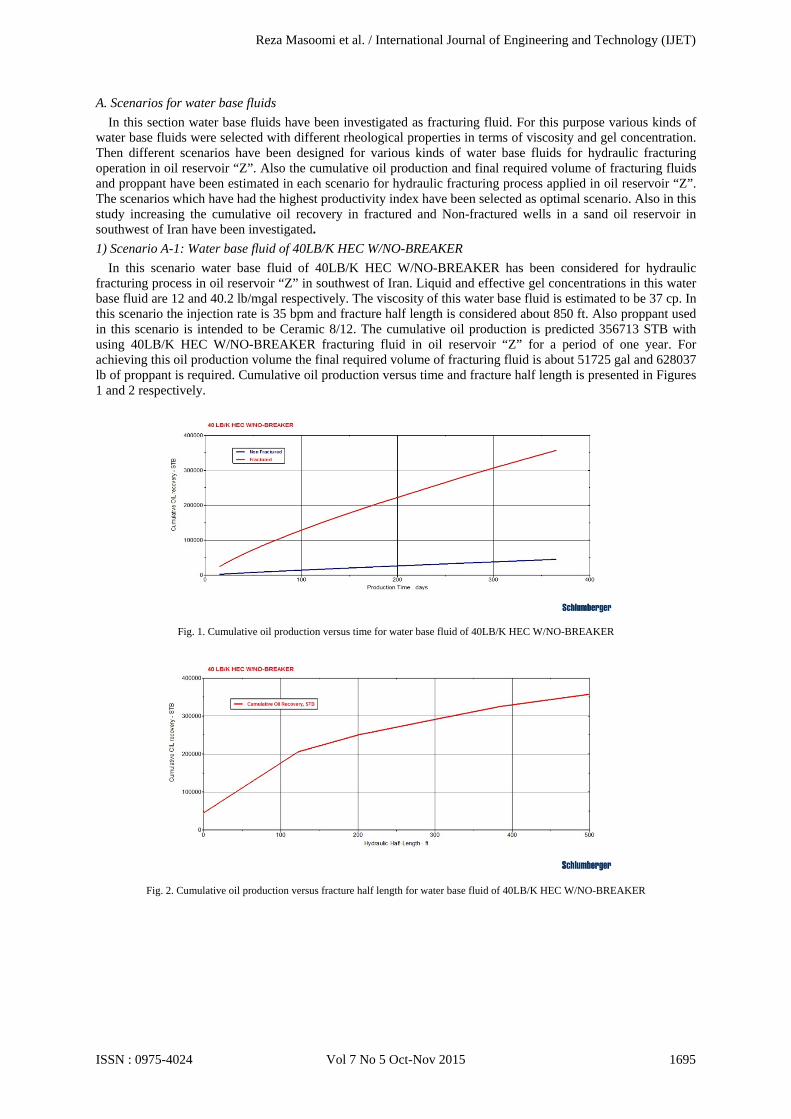
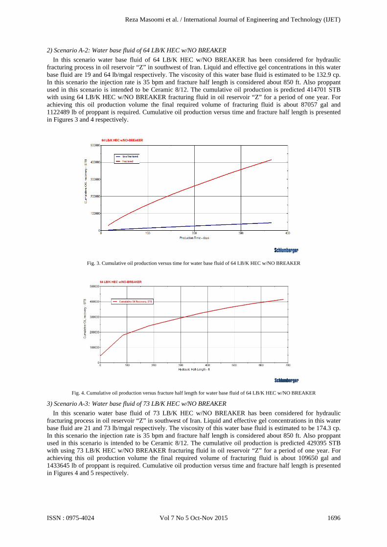
fracturing process in oil reservoir “Z” in southwest of Iran. Liquid and effective gel concentrations in this water base fluid are 19 and 64 lb/mgal respectively. The viscosity of this water base fluid is estimated to be 132.9 cp. In this scenario the injection rate is 35 bpm and fracture half length is considered about 850 ft. Also proppant used in this scenario is intended to be Ceramic 8/12. The cumulative oil production is predicted 414701 STB with using 64 LB/K HEC w/NO BREAKER fracturing fluid in oil reservoir “Z” for a period of one year. For achieving this oil production volume the final required volume of fracturing fluid is about 87057 gal and 1122489 lb of proppant is required. Cumulative oil production versus time and fracture half length is presented in Figures 3 and 4 respectively.
Fig. 3. Cumulative oil production versus time for water base fluid of 64 LB/K HEC w/NO BREAKER
Fig. 4. Cumulative oil production versus fracture half length for water base fluid of 64 LB/K HEC w/NO BREAKER
3) Scenario A-3: Water base fluid of 73 LB/K HEC w/NO BREAKER In this scenario water base fluid of 73 LB/K HEC w/NO BREAKER has been considered for hydraulic
fracturing process in oil reservoir “Z” in southwest of Iran. Liquid and effective gel concentrations in this water base fluid are 21 and 73 lb/mgal respectively. The viscosity of this water base fluid is estimated to be 174.3 cp. In this scenario the injection rate is 35 bpm and fracture half length is considered about 850 ft. Also proppant used in this scenario is intended to be Ceramic 8/12. The cumulative oil production is predicted 429395 STB with using 73 LB/K HEC w/NO BREAKER fracturing fluid in oil reservoir “Z” for a period of one year. For achieving this oil production volume the final required volume of fracturing fluid is about 109650 gal and 1433645 lb of proppant is required. Cumulative oil production versus time and fracture half length is presented in Figures 4 and 5 respectively.
Reza Masoomi et al. / International Journal of Engineering and Technology (IJET)
ISSN : 0975-4024 Vol 7 No 5 Oct-Nov 2015 1696
Fig. 4. Cumulative oil production versus time for water base fluid of 73 LB/K HEC w/NO BREAKER
Fig. 5. Cumulative oil production versus fracture half length for water base fluid of 73 LB/K HEC w/NO BREAKER
4) Scenario A-4: Water base fluid of 77 LB/K HEC w/NO-BREAKER In this scenario water base fluid of 77 LB/K HEC w/NO-BREAKER has been considered for hydraulic
fracturing process in oil reservoir “Z” in southwest of Iran. Liquid and effective gel concentrations in this water base fluid are 23 and 77.1 lb/mgal respectively. The viscosity of this water base fluid is estimated to be 132.9 cp. In this scenario the injection rate is 35 bpm and fracture half length is considered about 850 ft. Also proppant used in this scenario is intended to be Ceramic 8/12. The cumulative oil production is predicted 405815 STB with using 77 LB/K HEC w/NO-BREAKER fracturing fluid in oil reservoir “Z” for a period of one year. For achieving this oil production volume the final required volume of fracturing fluid is about 79533 gal and 1020385 lb of proppant is required. Cumulative oil production versus time and fracture half length is presented in Figures 6 and 7 respectively.
Reza Masoomi et al. / International Journal of Engineering and Technology (IJET)
ISSN : 0975-4024 Vol 7 No 5 Oct-Nov 2015 1697
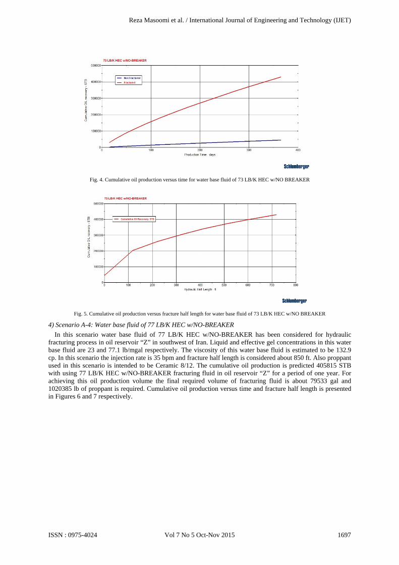
Fig. 6. Cumulative oil production versus time for water base fluid of 77 LB/K HEC w/NO-BREAKER
Fig. 7. Cumulative oil production versus fracture half length for water base fluid of 77 LB/K HEC w/NO-BREAKER
5) Scenario A-5: Water base fluid of 82 LB/K HEC w/NO-BREAKER In this scenario water base fluid of 82 LB/K HEC w/NO-BREAKER has been considered for hydraulic
fracturing process in oil reservoir “Z” in southwest of Iran. Liquid and effective gel concentrations in this water base fluid are 24 and 82.1 lb/mgal respectively. The viscosity of this water base fluid is estimated to be 214.2 cp. In this scenario the injection rate is 35 bpm and fracture half length is considered about 850 ft. Also proppant used in this scenario is intended to be Ceramic 8/12. The cumulative oil production is predicted 434783 STB with using 82 LB/K HEC w/NO-BREAKER fracturing fluid in oil reservoir “Z” for a period of one year. For achieving this oil production volume the final required volume of fracturing fluid is about 121238 gal and 1591438 lb of proppant is required. Cumulative oil production versus time and fracture half length is presented in Figures 8 and 9 respectively.
Reza Masoomi et al. / International Journal of Engineering and Technology (IJET)
ISSN : 0975-4024 Vol 7 No 5 Oct-Nov 2015 1698
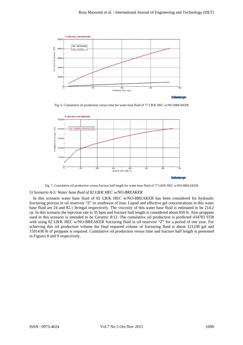
Fig. 8. Cumulative oil production versus time for water base fluid of 82 LB/K HEC w/NO-BREAKER
Fig. 9. Cumulative oil production versus fracture half length for water base fluid of 82 LB/K HEC w/NO-BREAKER
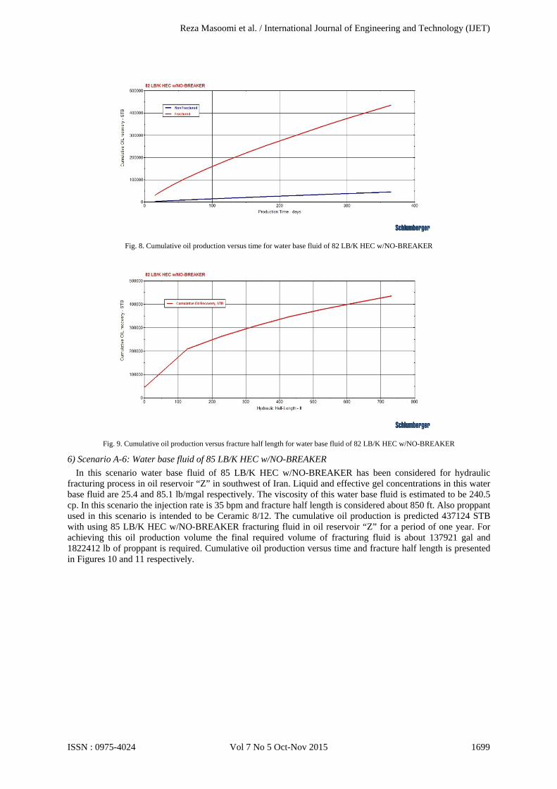
6) Scenario A-6: Water base fluid of 85 LB/K HEC w/NO-BREAKER In this scenario water base fluid of 85 LB/K HEC w/NO-BREAKER has been considered for hydraulic
fracturing process in oil reservoir “Z” in southwest of Iran. Liquid and effective gel concentrations in this water base fluid are 25.4 and 85.1 lb/mgal respectively. The viscosity of this water base fluid is estimated to be 240.5 cp. In this scenario the injection rate is 35 bpm and fracture half length is considered about 850 ft. Also proppant used in this scenario is intended to be Ceramic 8/12. The cumulative oil production is predicted 437124 STB with using 85 LB/K HEC w/NO-BREAKER fracturing fluid in oil reservoir “Z” for a period of one year. For achieving this oil production volume the final required volume of fracturing fluid is about 137921 gal and 1822412 lb of proppant is required. Cumulative oil production versus time and fracture half length is presented in Figures 10 and 11 respectively.
Reza Masoomi et al. / International Journal of Engineering and Technology (IJET)
ISSN : 0975-4024 Vol 7 No 5 Oct-Nov 2015 1699
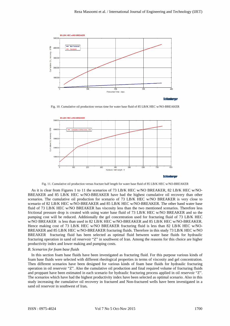
Fig. 10. Cumulative oil production versus time for water base fluid of 85 LB/K HEC w/NO-BREAKER
Fig. 11. Cumulative oil production versus fracture half length for water base fluid of 85 LB/K HEC w/NO-BREAKER
As it is clear from Figures 1 to 11 the scenarios of 73 LB/K HEC w/NO BREAKER, 82 LB/K HEC w/NO-BREAKER and 85 LB/K HEC w/NO-BREAKER have had the highest cumulative oil recovery than other scenarios. The cumulative oil production for scenario of 73 LB/K HEC w/NO BREAKER is very close to scenario of 82 LB/K HEC w/NO-BREAKER and 85 LB/K HEC w/NO-BREAKER. The other hand water base fluid of 73 LB/K HEC w/NO BREAKER has viscosity less than the two mentioned scenarios. Therefore less frictional pressure drop is created with using water base fluid of 73 LB/K HEC w/NO BREAKER and so the pumping cost will be reduced. Additionally the gel concentration used for fracturing fluid of 73 LB/K HEC w/NO BREAKER is less than used in 82 LB/K HEC w/NO-BREAKER and 85 LB/K HEC w/NO-BREAKER. Hence making cost of 73 LB/K HEC w/NO BREAKER fracturing fluid is less than 82 LB/K HEC w/NO-BREAKER and 85 LB/K HEC w/NO-BREAKER fracturing fluids. Therefore in this study 73 LB/K HEC w/NO BREAKER fracturing fluid has been selected as optimal fluid between water base fluids for hydraulic fracturing operation in sand oil reservoir “Z” in southwest of Iran. Among the reasons for this choice are higher productivity index and lower making and pumping costs. B. Scenarios for foam base fluids
In this section foam base fluids have been investigated as fracturing fluid. For this purpose various kinds of foam base fluids were selected with different rheological properties in terms of viscosity and gel concentration. Then different scenarios have been designed for various kinds of foam base fluids for hydraulic fracturing operation in oil reservoir “Z”. Also the cumulative oil production and final required volume of fracturing fluids and proppant have been estimated in each scenario for hydraulic fracturing process applied in oil reservoir “Z”. The scenarios which have had the highest productivity index have been selected as optimal scenario. Also in this study increasing the cumulative oil recovery in fractured and Non-fractured wells have been investigated in a sand oil reservoir in southwest of Iran.
Reza Masoomi et al. / International Journal of Engineering and Technology (IJET)
ISSN : 0975-4024 Vol 7 No 5 Oct-Nov 2015 1700
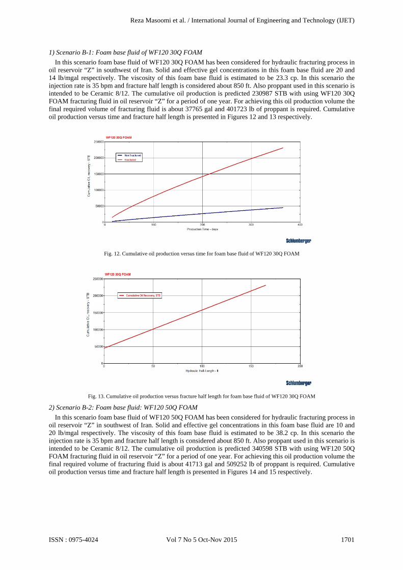
1) Scenario B-1: Foam base fluid of WF120 30Q FOAM In this scenario foam base fluid of WF120 30Q FOAM has been considered for hydraulic fracturing process in
oil reservoir “Z” in southwest of Iran. Solid and effective gel concentrations in this foam base fluid are 20 and 14 lb/mgal respectively. The viscosity of this foam base fluid is estimated to be 23.3 cp. In this scenario the injection rate is 35 bpm and fracture half length is considered about 850 ft. Also proppant used in this scenario is intended to be Ceramic 8/12. The cumulative oil production is predicted 230987 STB with using WF120 30Q FOAM fracturing fluid in oil reservoir “Z” for a period of one year. For achieving this oil production volume the final required volume of fracturing fluid is about 37765 gal and 401723 lb of proppant is required. Cumulative oil production versus time and fracture half length is presented in Figures 12 and 13 respectively.
Fig. 12. Cumulative oil production versus time for foam base fluid of WF120 30Q FOAM
Fig. 13. Cumulative oil production versus fracture half length for foam base fluid of WF120 30Q FOAM
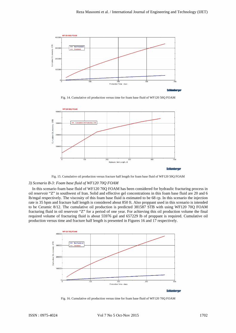
2) Scenario B-2: Foam base fluid: WF120 50Q FOAM In this scenario foam base fluid of WF120 50Q FOAM has been considered for hydraulic fracturing process in
oil reservoir “Z” in southwest of Iran. Solid and effective gel concentrations in this foam base fluid are 10 and 20 lb/mgal respectively. The viscosity of this foam base fluid is estimated to be 38.2 cp. In this scenario the injection rate is 35 bpm and fracture half length is considered about 850 ft. Also proppant used in this scenario is intended to be Ceramic 8/12. The cumulative oil production is predicted 340598 STB with using WF120 50Q FOAM fracturing fluid in oil reservoir “Z” for a period of one year. For achieving this oil production volume the final required volume of fracturing fluid is about 41713 gal and 509252 lb of proppant is required. Cumulative oil production versus time and fracture half length is presented in Figures 14 and 15 respectively.
Reza Masoomi et al. / International Journal of Engineering and Technology (IJET)
ISSN : 0975-4024 Vol 7 No 5 Oct-Nov 2015 1701
Fig. 14. Cumulative oil production versus time for foam base fluid of WF120 50Q FOAM
Fig. 15. Cumulative oil production versus fracture half length for foam base fluid of WF120 50Q FOAM
3) Scenario B-3: Foam base fluid of WF120 70Q FOAM In this scenario foam base fluid of WF120 70Q FOAM has been considered for hydraulic fracturing process in
oil reservoir “Z” in southwest of Iran. Solid and effective gel concentrations in this foam base fluid are 20 and 6 lb/mgal respectively. The viscosity of this foam base fluid is estimated to be 68 cp. In this scenario the injection rate is 35 bpm and fracture half length is considered about 850 ft. Also proppant used in this scenario is intended to be Ceramic 8/12. The cumulative oil production is predicted 381587 STB with using WF120 70Q FOAM fracturing fluid in oil reservoir “Z” for a period of one year. For achieving this oil production volume the final required volume of fracturing fluid is about 55976 gal and 657229 lb of proppant is required. Cumulative oil production versus time and fracture half length is presented in Figures 16 and 17 respectively.
Fig. 16. Cumulative oil production versus time for foam base fluid of WF120 70Q FOAM
Reza Masoomi et al. / International Journal of Engineering and Technology (IJET)
ISSN : 0975-4024 Vol 7 No 5 Oct-Nov 2015 1702
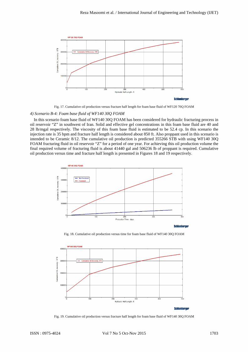
Fig. 17. Cumulative oil production versus fracture half length for foam base fluid of WF120 70Q FOAM
4) Scenario B-4: Foam base fluid of WF140 30Q FOAM In this scenario foam base fluid of WF140 30Q FOAM has been considered for hydraulic fracturing process in
oil reservoir “Z” in southwest of Iran. Solid and effective gel concentrations in this foam base fluid are 40 and 28 lb/mgal respectively. The viscosity of this foam base fluid is estimated to be 52.4 cp. In this scenario the injection rate is 35 bpm and fracture half length is considered about 850 ft. Also proppant used in this scenario is intended to be Ceramic 8/12. The cumulative oil production is predicted 355266 STB with using WF140 30Q FOAM fracturing fluid in oil reservoir “Z” for a period of one year. For achieving this oil production volume the final required volume of fracturing fluid is about 41440 gal and 506236 lb of proppant is required. Cumulative oil production versus time and fracture half length is presented in Figures 18 and 19 respectively.
Fig. 18. Cumulative oil production versus time for foam base fluid of WF140 30Q FOAM
Fig. 19. Cumulative oil production versus fracture half length for foam base fluid of WF140 30Q FOAM
Reza Masoomi et al. / International Journal of Engineering and Technology (IJET)
ISSN : 0975-4024 Vol 7 No 5 Oct-Nov 2015 1703
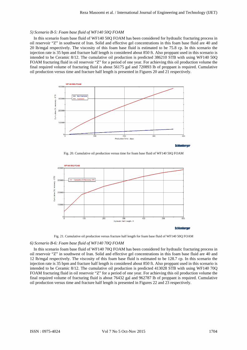
5) Scenario B-5: Foam base fluid of WF140 50Q FOAM In this scenario foam base fluid of WF140 50Q FOAM has been considered for hydraulic fracturing process in
oil reservoir “Z” in southwest of Iran. Solid and effective gel concentrations in this foam base fluid are 40 and 20 lb/mgal respectively. The viscosity of this foam base fluid is estimated to be 75.8 cp. In this scenario the injection rate is 35 bpm and fracture half length is considered about 850 ft. Also proppant used in this scenario is intended to be Ceramic 8/12. The cumulative oil production is predicted 386210 STB with using WF140 50Q FOAM fracturing fluid in oil reservoir “Z” for a period of one year. For achieving this oil production volume the final required volume of fracturing fluid is about 56175 gal and 720893 lb of proppant is required. Cumulative oil production versus time and fracture half length is presented in Figures 20 and 21 respectively.
Fig. 20. Cumulative oil production versus time for foam base fluid of WF140 50Q FOAM
Fig. 21. Cumulative oil production versus fracture half length for foam base fluid of WF140 50Q FOAM
6) Scenario B-6: Foam base fluid of WF140 70Q FOAM In this scenario foam base fluid of WF140 70Q FOAM has been considered for hydraulic fracturing process in
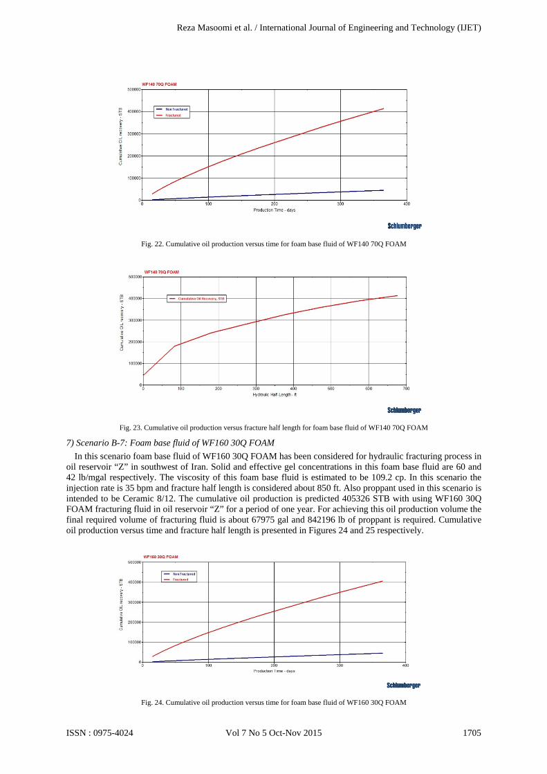
oil reservoir “Z” in southwest of Iran. Solid and effective gel concentrations in this foam base fluid are 40 and 12 lb/mgal respectively. The viscosity of this foam base fluid is estimated to be 128.7 cp. In this scenario the injection rate is 35 bpm and fracture half length is considered about 850 ft. Also proppant used in this scenario is intended to be Ceramic 8/12. The cumulative oil production is predicted 413028 STB with using WF140 70Q FOAM fracturing fluid in oil reservoir “Z” for a period of one year. For achieving this oil production volume the final required volume of fracturing fluid is about 76432 gal and 962787 lb of proppant is required. Cumulative oil production versus time and fracture half length is presented in Figures 22 and 23 respectively.
Reza Masoomi et al. / International Journal of Engineering and Technology (IJET)
ISSN : 0975-4024 Vol 7 No 5 Oct-Nov 2015 1704
Fig. 22. Cumulative oil production versus time for foam base fluid of WF140 70Q FOAM
Fig. 23. Cumulative oil production versus fracture half length for foam base fluid of WF140 70Q FOAM
7) Scenario B-7: Foam base fluid of WF160 30Q FOAM In this scenario foam base fluid of WF160 30Q FOAM has been considered for hydraulic fracturing process in
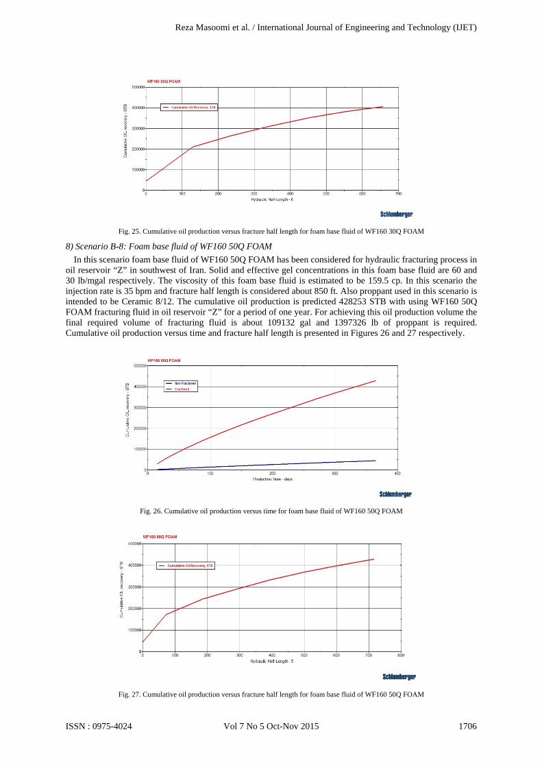
oil reservoir “Z” in southwest of Iran. Solid and effective gel concentrations in this foam base fluid are 60 and 42 lb/mgal respectively. The viscosity of this foam base fluid is estimated to be 109.2 cp. In this scenario the injection rate is 35 bpm and fracture half length is considered about 850 ft. Also proppant used in this scenario is intended to be Ceramic 8/12. The cumulative oil production is predicted 405326 STB with using WF160 30Q FOAM fracturing fluid in oil reservoir “Z” for a period of one year. For achieving this oil production volume the final required volume of fracturing fluid is about 67975 gal and 842196 lb of proppant is required. Cumulative oil production versus time and fracture half length is presented in Figures 24 and 25 respectively.
Fig. 24. Cumulative oil production versus time for foam base fluid of WF160 30Q FOAM
Reza Masoomi et al. / International Journal of Engineering and Technology (IJET)
ISSN : 0975-4024 Vol 7 No 5 Oct-Nov 2015 1705
Fig. 25. Cumulative oil production versus fracture half length for foam base fluid of WF160 30Q FOAM
8) Scenario B-8: Foam base fluid of WF160 50Q FOAM In this scenario foam base fluid of WF160 50Q FOAM has been considered for hydraulic fracturing process in
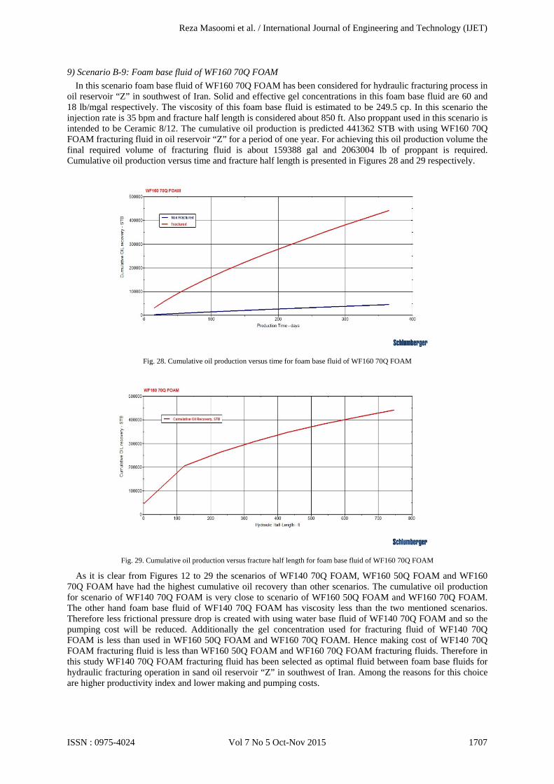
oil reservoir “Z” in southwest of Iran. Solid and effective gel concentrations in this foam base fluid are 60 and 30 lb/mgal respectively. The viscosity of this foam base fluid is estimated to be 159.5 cp. In this scenario the injection rate is 35 bpm and fracture half length is considered about 850 ft. Also proppant used in this scenario is intended to be Ceramic 8/12. The cumulative oil production is predicted 428253 STB with using WF160 50Q FOAM fracturing fluid in oil reservoir “Z” for a period of one year. For achieving this oil production volume the final required volume of fracturing fluid is about 109132 gal and 1397326 lb of proppant is required. Cumulative oil production versus time and fracture half length is presented in Figures 26 and 27 respectively.
Fig. 26. Cumulative oil production versus time for foam base fluid of WF160 50Q FOAM
Fig. 27. Cumulative oil production versus fracture half length for foam base fluid of WF160 50Q FOAM
Reza Masoomi et al. / International Journal of Engineering and Technology (IJET)
ISSN : 0975-4024 Vol 7 No 5 Oct-Nov 2015 1706
9) Scenario B-9: Foam base fluid of WF160 70Q FOAM In this scenario foam base fluid of WF160 70Q FOAM has been considered for hydraulic fracturing process in
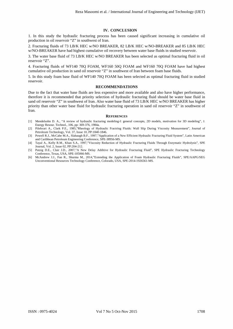
oil reservoir “Z” in southwest of Iran. Solid and effective gel concentrations in this foam base fluid are 60 and 18 lb/mgal respectively. The viscosity of this foam base fluid is estimated to be 249.5 cp. In this scenario the injection rate is 35 bpm and fracture half length is considered about 850 ft. Also proppant used in this scenario is intended to be Ceramic 8/12. The cumulative oil production is predicted 441362 STB with using WF160 70Q FOAM fracturing fluid in oil reservoir “Z” for a period of one year. For achieving this oil production volume the final required volume of fracturing fluid is about 159388 gal and 2063004 lb of proppant is required. Cumulative oil production versus time and fracture half length is presented in Figures 28 and 29 respectively.
Fig. 28. Cumulative oil production versus time for foam base fluid of WF160 70Q FOAM
Fig. 29. Cumulative oil production versus fracture half length for foam base fluid of WF160 70Q FOAM
As it is clear from Figures 12 to 29 the scenarios of WF140 70Q FOAM, WF160 50Q FOAM and WF160 70Q FOAM have had the highest cumulative oil recovery than other scenarios. The cumulative oil production for scenario of WF140 70Q FOAM is very close to scenario of WF160 50Q FOAM and WF160 70Q FOAM. The other hand foam base fluid of WF140 70Q FOAM has viscosity less than the two mentioned scenarios. Therefore less frictional pressure drop is created with using water base fluid of WF140 70Q FOAM and so the pumping cost will be reduced. Additionally the gel concentration used for fracturing fluid of WF140 70Q FOAM is less than used in WF160 50Q FOAM and WF160 70Q FOAM. Hence making cost of WF140 70Q FOAM fracturing fluid is less than WF160 50Q FOAM and WF160 70Q FOAM fracturing fluids. Therefore in this study WF140 70Q FOAM fracturing fluid has been selected as optimal fluid between foam base fluids for hydraulic fracturing operation in sand oil reservoir “Z” in southwest of Iran. Among the reasons for this choice are higher productivity index and lower making and pumping costs.
Reza Masoomi et al. / International Journal of Engineering and Technology (IJET)
ISSN : 0975-4024 Vol 7 No 5 Oct-Nov 2015 1707
IV. CONCLUSION
1. In this study the hydraulic fracturing process has been caused significant increasing in cumulative oil production in oil reservoir “Z” in southwest of Iran. 2. Fracturing fluids of 73 LB/K HEC w/NO BREAKER, 82 LB/K HEC w/NO-BREAKER and 85 LB/K HEC w/NO-BREAKER have had highest cumulative oil recovery between water base fluids in studied reservoir. 3. The water base fluid of 73 LB/K HEC w/NO BREAKER has been selected as optimal fracturing fluid in oil reservoir “Z”. 4. Fracturing fluids of WF140 70Q FOAM, WF160 50Q FOAM and WF160 70Q FOAM have had highest cumulative oil production in sand oil reservoir “Z” in southwest of Iran between foam base fluids. 5. In this study foam base fluid of WF140 70Q FOAM has been selected as optimal fracturing fluid in studied reservoir.
RECOMMENDATIONS
Due to the fact that water base fluids are less expensive and more available and also have higher performance, therefore it is recommended that priority selection of hydraulic fracturing fluid should be water base fluid in sand oil reservoir “Z” in southwest of Iran. Also water base fluid of 73 LB/K HEC w/NO BREAKER has higher priority than other water base fluid for hydraulic fracturing operation in sand oil reservoir “Z” in southwest of Iran.
REFERENCES [1] Mendelsohn D. A., “A review of hydraulic fracturing modeling-l: general concepts, 2D models, motivation for 3D modeling”, J.
Energy Resour. Technol., 106, pp: 369-376, 1984a. [2] Pilehvari A., Clark P.E., 1985,”Rheology of Hydraulic Fractring Fluids: Wall Slip During Viscosity Measurement”, Journal of
Petroleum Technology, Vol. 37, Issue 10, PP:1840-1846. [3] Powell R.J., McCabe M.A., Slabaugh B.F., 1997,”Application of a New Efficient Hydraulic Fracturing Fluid System”, Latin American
and Caribbean Petroleum Engineering Conference, SPE-38956-MS. [4] Tayal A., Kelly R.M., Khan S.A., 1997,”Viscosity Reduction of Hydraulic Fracturing Fluids Through Enzymatic Hydrolysis”, SPE
Conference, Texas, USA, SPE-105066-MS. [6] McAndrew J.J., Fan R., Shurma M., 2014,”Extending the Application of Foam Hydraulic Fracturing Fluids”, SPE/AAPG/SEG
Unconventional Resources Technology Conference, Colorado, USA, SPE-2014-1926561-MS.
Reza Masoomi et al. / International Journal of Engineering and Technology (IJET)