OPTIMIZATION OF LONGITUDINAL FIN PROFILE FOR DOUBLE PIPE HEAT
EXCHANGER
MONICA J. INDHE1, V.W.BHATKAR2
1M.E. Mechanical (Heat Power), G.S. Moze College Of Engg. Balewadi,Pune, Maharashtra,India
2Assistant Professor, Department of Mechanical Engineering, M.M. College of Engineering, Pune,
Maharashtra,India
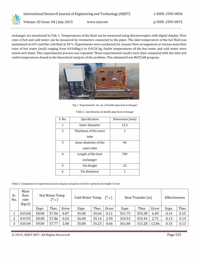
ABSTRACT In the present study the performance of the heat transfer process in a given heat exchanger is determined for longitudinal
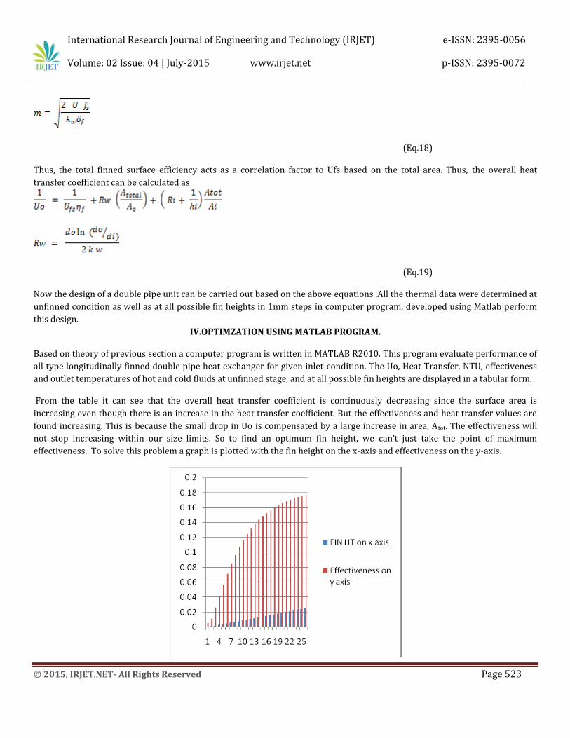
fin profiles (rectangular). The performance of a double pipe heat exchanger is analyzed in two parts that is optimization and experimentation. In the part of optimization numerical analysis performed by Matlab program. This program will serve to optimize the fin height so as to obtain maximum possible heat transfer without any wastage of material at a given length and inlet conditions. Also all the performance parameter such as efficiency, pressure drop, effectiveness, heat transfer coefficient, outlet temperature of both fluid, overall heat transfer coefficient studied same time for all possible fin height.
In second part experimentation is carried out in a counter flow double pipe heat exchanger for varied mass flow rate which ranges from 0.0168 kg/s to 0.0126 kg/s. Experimental results and analytical result shows for optimum height is effectiveness increase up to 23% and heat transfer is enhanced by 26% than unfinned pipe .Also in case of varying mass flow rate for 0.0126 kg/s give good effectiveness and heat transfer than 0.0126 kg/s mass flow rate Keywords: Fin height, optimization, double pipe heat exchanger, longitudinal fin, effectiveness.
I. INTRODUCTION
Heat exchangers are used to transfer that energy from high temperature liquid to low temperature. Temperature of
incoming and outgoing fluid is important . As per requirement heat exchangers raise or lower the temperature of these fluids
by transferring heat to or from the fluid.
Double pipe heat exchangers are simplest devices in which fluid separated by cylindrical wall. Application of double pipe heat
exchanger is in high temperature and high pressure .as compared other exchanger they required space but they are fairly
cheap. Hence for the given design and length of the heat exchanger heat transfer enhancement in a double pipe heat exchanger
is possibly achieved by several methods. These techniques are divided into active and passive techniques. Active methods
involve internal parameter optimization. Another method is the passive method in which stimulation by external power such
as surface coating, surface roughness and extended surfaces.
Several papers have studied and concluded that proper fin selection can help in obtaining substantial increase in the values of
heat transfer coefficients and effectiveness of a heat exchanger. This also demonstrates the fact that Fins provide a
thermodynamic advantage. Thereby designing a heat exchanger at the optimum fin height can lead to reducing capital costs
and increasing savings. Also providing cheap materials for the fin and expensive durable materials for thinner pipes can
increase Heat Exchanger Lifespan and save capital costs as well.
International Research Journal of Engineering and Technology (IRJET) e-ISSN: 2395-0056
Kw is the tube wall thermal conductivity .The tube resistance term can be determined for the case of steady state conduction
through the walls of a symmetric cylinder. The overall heat transfer coefficient Uo is defined on the outside surface area of the
(plain) pipe Ao. For double pipe configuration heat transfer area can be put as
where L is the length of the tube surface and d is the corresponding diameter (do for outer and di for inner surface giving Ao
and Ai respectively). This reduces the Eq.4
(Eq.5)
• First, calculations are carried out with properties at the mean bulk temperature on each side where
On the basis of result obtained the wall temperature at each end can be calculated by temperature drop from the hot stream and temperature rise in the cold stream. At the hot fluid inlet wall temperature may be approximately calculated as
(Eq.6)
And at the cold fluid inlet the wall temperature is calculated as
(Eq.7)
Here the wall resistance is divided into two (may be equal) parts and added to film and fouling resistance of each side to get
Rcold and Rhot. With these wall temperatures on both the ends the mean wall temperature can be calculated and then the
properties can evaluated at the mean film temperature given by
(Eq.8)
This has to be iterated and within two to three iterations and a good converged result can be obtained.
International Research Journal of Engineering and Technology (IRJET) e-ISSN: 2395-0056
• If iteration is to be avoided we can assume that both U and T vary linearlywithin the heat exchanger. This gives an average
heat transfer coefficient Um as
(Eq.9)
Here the suffixes 1 and 2 refer to the ends of the heat exchanger.
For shell side heat transfer coefficient the equation for heat transfer coefficient in annulus has to be used. For turbulent flow
the same correlation can be used for tube flow only the diameter should be replaced by equivalent diameter, de. Here, one
important distinction has to be made between thermal and hydraulic performance. The fluid friction for the annular space
takes place at both the inner wall of the outer tube (shell) and outer wall of the inner tube, whereas, heat transfer takes place
at the outer surface of the inner tube. Thus, for evaluating the heat transfer coefficient of the annular side, the equivalent
diameter is calculated as
(Eq.10)
For fluid flow and the definition of the Reynolds Number, the hydraulic diameter should be used which is given by
(Eq.11)
where, o indicates outer surface of inner tube and ko is the thermal conductivity of the fluid in the annulus. However, the above quantities are for unfinned units only. For finned construction the details are given in design section later.
DESIGN OF LONGITUDINALLY FINNED DOUBLE PIPEHEAT EXCHANGERS:
Now let us define the previously defined quantities for finned construction.
Hydraulic Mean Diameter,
International Research Journal of Engineering and Technology (IRJET) e-ISSN: 2395-0056
Here we assume that heat transfer coefficient constant for entire fin length. Biot number is very small along thickness hence it can consider it one dimensional, the fin efficiency can be calculated as,
(Eq.14)
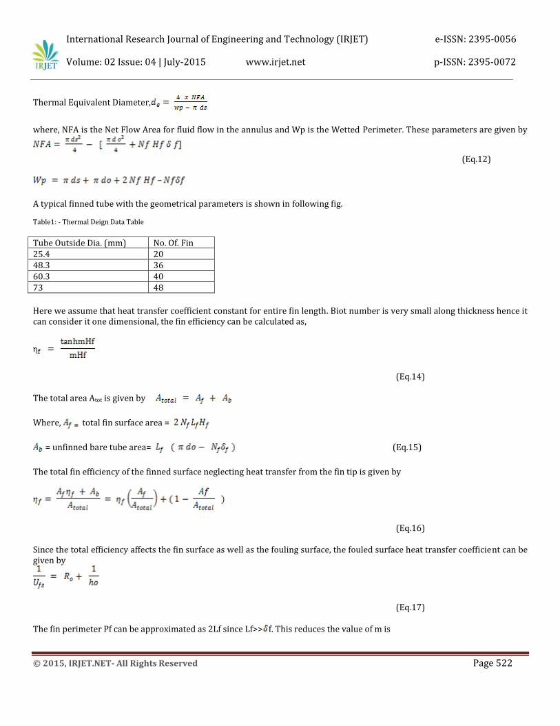
The total area Atot is given by
Where, total fin surface area =
= unfinned bare tube area= (Eq.15)
The total fin efficiency of the finned surface neglecting heat transfer from the fin tip is given by
(Eq.16)
Since the total efficiency affects the fin surface as well as the fouling surface, the fouled surface heat transfer coefficient can be given by
(Eq.17)
The fin perimeter Pf can be approximated as 2Lf since Lf>> f. This reduces the value of m is
International Research Journal of Engineering and Technology (IRJET) e-ISSN: 2395-0056
[9] Incropera, F.P.; and DeWitt, D.P. (2002). Fundamentals Of heat and mass Transfer. (5th Ed.), Wiley, New York. [10]Stephen Schneider, December 2000, Water Heat exchanger Optimization for Space
[11]Sundar L. S. and Sarma K. V., “Turbulent heat transfer and friction factor of Al2O3 nanofluid in a circular tube with twisted
tape inserts”,
International Communications in Heat and Mass transfer 53, pp.1409-1416, 2010.
[12] Li Zhang, Hongmei Guo, Jianhua Wu, Wenjuan Du, “Compound Heat Transfer Enhancement for Shell Side of Double-Pipe
Heat Exchanger by Helical Fins and Vortex Generators”, Heat Mass Transfer, Vol. 48, pp 1113 – 1124, 2012.
International Research Journal of Engineering and Technology (IRJET) e-ISSN: 2395-0056