Abstract Constant force mechanisms are mechanicaldevices that provide a near-constant output force overa sizable and prescribed deflection range. These mech-anisms have proven to be innovative solutions in avariety of applications. This paper considers a newapplication – the robust design optimization of con-stant force electrical contacts. Electrical contacts areinexpensive, small-scale, springs that carry electricalcurrent. To produce these contacts at competitively lowmanufacturing costs, expensive pin-joints (a principlecomponent of traditional kinematic mechanisms) arereplaced by simple cam followers. Under certain con-ditions, enforced in this paper, cam followers can beused to emulate traditional pin-joints, and achieve thenecessary motion. These emulated pin-joints, however,are subject to mating/assembly uncertainties that affectperformance and must be considered in the design. Inthis paper, a numerical optimization model is used tocharacterize the force-deflection relationships for bothan exactly mated emulated pin-joint, and for one that issubject to mating uncertainties. The numerical resultsshow that under the exact mating conditions, a contactwith 97.50% constant force can be identified (an im-provement of 24.3% over previously published results),albeit sensitive to mating uncertainty. When conditionsare considered uncertain, a more robust design is foundwith a 98.20% constant force. These surprising resultsare described in detail and verified with Monte Carlosimulation to confirm the results.
J. C. Meaders · C. A. Mattson (B)Department of Mechanical Engineering,Brigham Young University, Provo, UT 84602, USAe-mail: [email protected]
Keywords Constant force mechanism · Non-linearfinite element analysis · Multiobjective optimization ·Robust design optimization · Electrical contact
Nomenclature
αc Smallest angle between the cam link and thepreceding element before deformation
γc Smallest angle between the cam link and thepreceding element after deformation
αi Smallest angle between the i-th element and thei + 1 element
βmax Maximum transmission angle that the optimiza-tion search allows between the cam and thepreceding element
C Percent constant force� Total deflection (prescribed)δp Preload deflectionδ An increment of the total prescribed deflection
�
dij Minimum distance between the i-th element andthe jth element
F Output force�x Size of the design domain in x direction�y Size of the design domain in y directionLi Length of the i-th elementN Safety Factor on Stressnn Number of nodesne Number of elementsp Vector of designer specified parametersψ Minimum angle allowed between the cam link
and the vertical and horizontal positionsθc Angle of the cam link as measured from the
horizontalRi Distance from the i-th node to the cam center
2 J.C. Meaders, C.A. Mattson
rc Radius of the camσmax Maximum Bending Stressx Vector of nodal coordinates in x directiony Vector of nodal coordinates in y directionYs Yield Strength
1 Introduction
From time to time, designs would benefit from havingsprings that exhibit a near-constant output force overa sizable, and prescribed, displacement range. Thesesprings, whose force-displacement curves are notablydifferent than linear springs, are referred to as constantforce springs (Weight et al. 2007).
The constant force springs considered in this paperare derived from a broader class of constant force de-vices characterized as constant force kinematic mecha-nisms, which are modelled using traditional kinematicanalysis (Howell 2001; Nahar and Sugar 2003; Evansand Howell 1999; Howell and Magleby 2006). Whilethe constant force springs presented in this paper arekinematic mechanisms, they do not possess revolutejoints (pin-joints). Instead, the necessary motion is ob-tained by (i) the large deflection of the spring’s sections,and (ii) by simple cam followers, which can emulatethe motion of a revolute-joint. These cam followersare described shortly, and are hereafter referred to asemulated pin-joints.
In this paper we present the design optimizationof constant-force springs with emulated pin-joints andwith consideration of uncertainty in the emulated pin-joint mating conditions. We specifically focus on the de-sign of small scale (roughly 6 mm tall), mass producedelectrical contacts, the basic architecture of which isshown in Fig. 1. The purpose of the electrical contactis to provide a reliable and separable electrical con-nection between two electrical devices. The constantforce contact is designed to carry out that purpose withminimal variation in output force, which is a promisingsolution to common signal-integrity-difficulties encoun-tered in separable electrical interconnections (Weightet al. 2007).
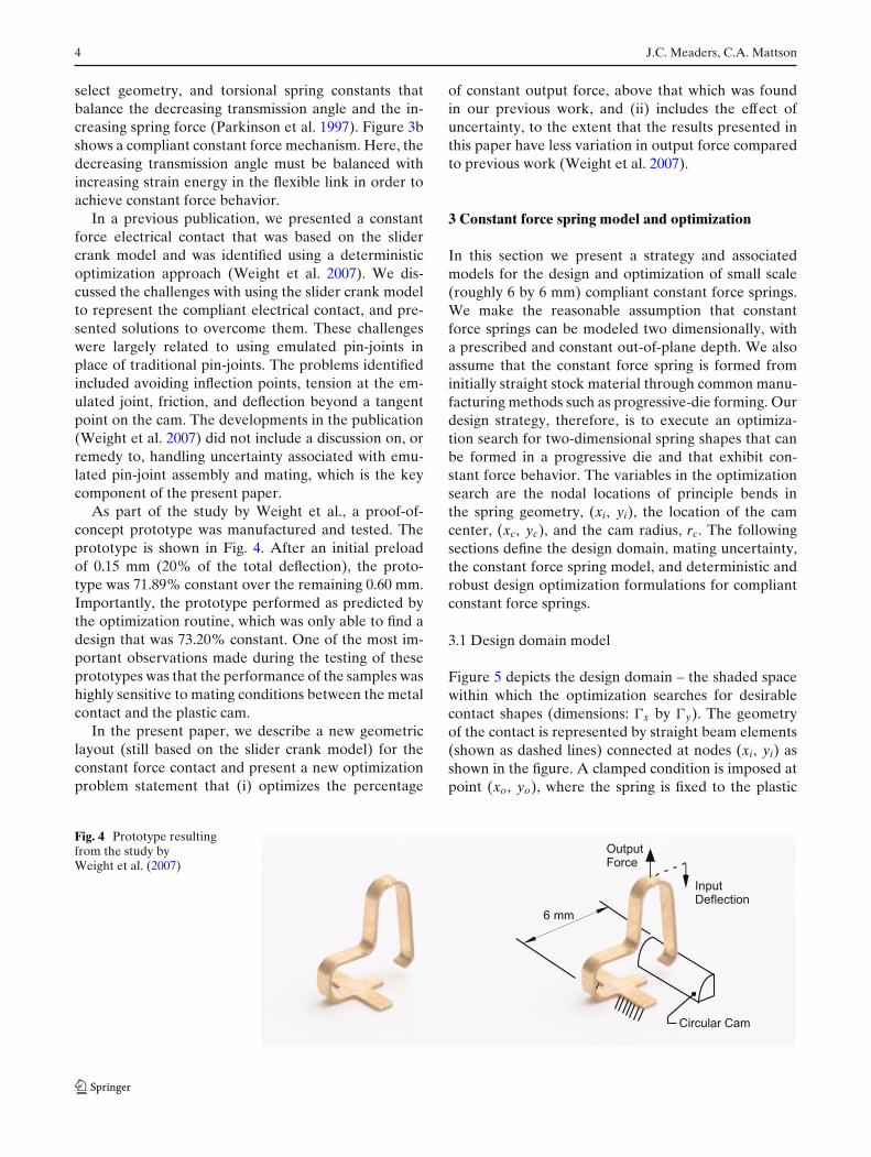
As illustrated in Fig. 1, the constant force contactassembly comprises (i) a plastic housing, and (ii) ametallic beam that is fixed at one end to the hous-ing and makes contact with a plastic cam surface onthe other. When the electrical connection is made, adevice to which the connector mates applies a largedisplacement (labeled Input Deflection) to a point onthe beam. This creates a reaction force (labeled OutputForce) which is designed to be relatively constant overa large displacement range. The actual magnitude of
Input
Deflection
Output
Force Fixed End
Plastic
Housing
Metallic
Spring
Fig. 1 Basic architecture of the compliant constant force electri-cal contact
displacement depends on several case-specific factorsincluding the geometry and stiffness of both devices.
To produce these contacts at competitively low man-ufacturing costs, emulated pin-joints have been usedin place of more expensive pin-joints. Under certainconditions, enforced in this paper, cam followers canbe used to emulate traditional pin-joints, and achievethe necessary kinematics. Figure 2 illustrates the de-finition of an emulated pin-joint. As shown in thefigure, the emulated pin-joint is located at the pointwhere the metallic beam contacts the circular plasticcam. This connection, if maintained in compression,simulates a traditional pin-joint between the metallicbeam and an imaginary rigid link connected to the camcenter and having a length equal to the cam radius,rc. These emulated joints, however, are subject to mat-ing/assembly uncertainties that can significantly changethe percent constant a mechanism’s output force is, ifnot considered and handled explicitly. While extensivework has been done to predict the effect of uncertaintyin traditional pin-joints (Garrett and Hall 1969; Choiet al. 1998) (by considering joint clearances), alterna-tive models are needed that consider large mating gapsand large interferences between the compliant metalspring and the plastic cam.
As described in this paper, we seek robust designsthat (i) exhibit a high constant force percentage, and(ii) are insensitive to mating/assembly uncertainties.Formally, a robust design can be defined as one whoseperformance remains relatively unchanged and feasi-ble in the presence of uncertainty (Chen et al. 2000).Optimization-based robust design approaches seek to
Optimization of near-constant force springs subject to mating uncertainty 3
Fig. 2 Side view of basicconstant force contactarchitecture; (a) Emulatedpin-joint between beam andcam. (b) traditional pin-jointbetween beam and cam
optimize the mean performance and minimize its vari-ation, while maintaining feasibility with probabilisticconstraints (Taguchi 1986; DeVor et al. 1992; Koch2002). The approach originates from Taguchi’s theorieson handling uncertainty in practice (Taguchi 1986).Noted work in this area includes Parkinson et al. (1993),and Chen et al. (1999, 2000). Su and Renaud (1997)provide an extensive review of the optimization-basedrobust design literature.
This paper presents a new design optimization ap-proach for constant force springs. The approach can in-corporate the uncertain nature of emulated pin-joints.Deterministic and robust design results are presentedand compared to deterministic results published byWeight et al. (2007). As shown, the design approachpresented here yields significant improvement over theprevious study (Weight et al. 2007).
2 Technical preliminaries
Various developments have been made for the generalmodeling and design of constant force mechanisms
(Jenuwine and Midha 1994; Herder and van den Berg2000; Nathan 1985). Among the most useful develop-ments is the Pseudo Rigid Body Model (PRBM); amethod for designing compliant constant force mecha-nisms (Howell 2001). Compliant mechanisms gain someor all of their motion from the large deflection offlexible members as opposed to movement of rigidlinks connected by pin-joints. The PRBM is used toanalyze compliant mechanisms as rigid-body mecha-nisms, thereby significantly reducing the complexity ofanalysis (Howell 2001; Evans and Howell 1999; Howelland Magleby 2006; Weight 2001).
One of the most common approaches for modelinga constant force mechanism is as a traditional slidercrank mechanism with torsional springs at some or allof the joints (Murphy et al. 1996; Weight et al. 2002;Frischknecht et al. 2004). Such a mechanism is shown inFig. 3a. The constant force behavior of this mechanismis due primarily to (i) the decreasing force transmissionangle, from greater than π/2 to π/2, between the twolong links in the figure, and (ii) the increasing springforce as the torsional spring deflects. To design constantforce mechanisms based on this model, a designer must
Fig. 3 (a) Compression-type constant force mechanism with rigid links and torsional springs at pin-joints. (b) One configuration of acompliant constant force mechanism with flexible and rigid links
4 J.C. Meaders, C.A. Mattson
select geometry, and torsional spring constants thatbalance the decreasing transmission angle and the in-creasing spring force (Parkinson et al. 1997). Figure 3bshows a compliant constant force mechanism. Here, thedecreasing transmission angle must be balanced withincreasing strain energy in the flexible link in order toachieve constant force behavior.
In a previous publication, we presented a constantforce electrical contact that was based on the slidercrank model and was identified using a deterministicoptimization approach (Weight et al. 2007). We dis-cussed the challenges with using the slider crank modelto represent the compliant electrical contact, and pre-sented solutions to overcome them. These challengeswere largely related to using emulated pin-joints inplace of traditional pin-joints. The problems identifiedincluded avoiding inflection points, tension at the em-ulated joint, friction, and deflection beyond a tangentpoint on the cam. The developments in the publication(Weight et al. 2007) did not include a discussion on, orremedy to, handling uncertainty associated with emu-lated pin-joint assembly and mating, which is the keycomponent of the present paper.
As part of the study by Weight et al., a proof-of-concept prototype was manufactured and tested. Theprototype is shown in Fig. 4. After an initial preloadof 0.15 mm (20% of the total deflection), the proto-type was 71.89% constant over the remaining 0.60 mm.Importantly, the prototype performed as predicted bythe optimization routine, which was only able to find adesign that was 73.20% constant. One of the most im-portant observations made during the testing of theseprototypes was that the performance of the samples washighly sensitive to mating conditions between the metalcontact and the plastic cam.
In the present paper, we describe a new geometriclayout (still based on the slider crank model) for theconstant force contact and present a new optimizationproblem statement that (i) optimizes the percentage
of constant output force, above that which was foundin our previous work, and (ii) includes the effect ofuncertainty, to the extent that the results presented inthis paper have less variation in output force comparedto previous work (Weight et al. 2007).
3 Constant force spring model and optimization
In this section we present a strategy and associatedmodels for the design and optimization of small scale(roughly 6 by 6 mm) compliant constant force springs.We make the reasonable assumption that constantforce springs can be modeled two dimensionally, witha prescribed and constant out-of-plane depth. We alsoassume that the constant force spring is formed frominitially straight stock material through common manu-facturing methods such as progressive-die forming. Ourdesign strategy, therefore, is to execute an optimiza-tion search for two-dimensional spring shapes that canbe formed in a progressive die and that exhibit con-stant force behavior. The variables in the optimizationsearch are the nodal locations of principle bends inthe spring geometry, (xi, yi), the location of the camcenter, (xc, yc), and the cam radius, rc. The followingsections define the design domain, mating uncertainty,the constant force spring model, and deterministic androbust design optimization formulations for compliantconstant force springs.
3.1 Design domain model
Figure 5 depicts the design domain – the shaded spacewithin which the optimization searches for desirablecontact shapes (dimensions: �x by �y). The geometryof the contact is represented by straight beam elements(shown as dashed lines) connected at nodes (xi, yi) asshown in the figure. A clamped condition is imposed atpoint (xo, yo), where the spring is fixed to the plastic
Fig. 4 Prototype resultingfrom the study byWeight et al. (2007)
Optimization of near-constant force springs subject to mating uncertainty 5
Γ y
Γ x
ElementNode
(xo, yo)
P
(xa, ya)
θ c
(xi, yi)
Δ
(0, 0)
α i
(xc, yc)
α c
Ri
Li
Fig. 5 Design domain and associated variables and parameters
housing. The geometry of the cam is depicted as a rigidkinematic link extending from the cam center (xc, yc) tothe free end of the formed spring. Under the determin-istic model, the free end of the cam link and the freeend of the beam are constrained to occupy the samelocation; in other words, two nodes in the finite elementmodel occupy the same spatial location. Additionally,with the no restriction on relative rotation between thecam link and the beam, these conditions characterize akinematic pin-joint. All nodes, except the cam center(xc, yc), are constrained to be within the shaded designdomain. Importantly, we note that allowing the camcenter location (xc, yc) to be outside the shaded designdomain brings additional freedom not present in pre-vious work (Weight et al. 2007). Since the cam link issolely used in simulation (i.e., not manufactured), onlythe portion of the cam that contacts the spring frominitial to final displacement is restricted to the designdomain.
Figure 5 also shows a prescribed deflection (�) ap-plied to a point (xa, ya) on the spring, and a reactionforce (P), which is determined in the vertical direction.While the point (xa, ya) is subject to a prescribeddeflection in the vertical direction, it is not constrainedin the horizontal direction. The total number of nodes(nn) and elements (ne) in the design is chosen accordingto the desired resolution of the finite element model.
Unlike the geometric model from our earlier work(Weight et al. 2007), the present design domain modeluses the Cartesian coordinates of each node (xi, yi)as variables for the design optimization. Because thenodal coordinates are permitted to be anywhere withinthe design domain, the optimization has nearly com-
plete freedom to search for spring shapes that provideconstant reactionary forces over large displacementranges.
Figure 5 also illustrates variables that are used to for-mulate behaviorial constraints that ensure that the re-sulting design will be both manufacturable, and withinthe predictive capabilities of the emulated pin-jointmodel. Specifically, we define the angle between twoadjacent elements (αi), the length of each element (Li),the distance from each node to the cam center (Ri), theangle between the cam link and the preceding element(αc), and the angle (θc) of the cam link as measuredfrom the horizontal. Each of these quantities is de-pendent on the nodal locations, which are independentvariables. The behaviorial constraints that rely on thesedependent variables are described shortly.
3.1.1 Geometric uncertainty model
When, at an undeflected spring state, it is assumed thatthe end of the spring is in perfect contact with the cam(i.e., no mating gap, and no strain in the spring), thesearch for desirable spring shapes can be carried out ina deterministic way. However, when the more realisticcondition of mating gaps or initial strain in the springis considered, a non-deterministic approach is needed.This section describes the geometric uncertainty modelused to capture these non-deterministic effects.
The geometric uncertainty model presented hereincludes two sources of uncertainty. One source of un-certainty arises from manufacturing variations in springshape, and by variations in other parameters such asmaterial properties. The other source of uncertaintyarises from imperfect mating conditions in the em-ulated pin-joint. To characterize the robustness of aparticular design with respect to variation in manufac-turing variables and other parameters we use a MonteCarlo simulation to create a population of contacts withnormally distributed values for the spring’s nodal loca-tions. For each spring in the population, the percentageof constant force is determined. The standard deviationof the constant force percentages across the populationdetermines the degree to which a design is robust.
Considering the second source of uncertainty, thereare several different mating conditions that may be ex-perienced between the assembled parts (metallic beamand plastic cam). Possible mating scenarios are illus-trated in Fig. 6. The first case (Fig. 6a) is an ideal casewhere the beam and the cam mate exactly as designed –inducing no strain and leaving no gap. In this case,a deterministic search is sufficient. The second case(Fig. 6b) occurs when the cam is manufactured with asmaller radius than the design target. This results in a
6 J.C. Meaders, C.A. Mattson
Fig. 6 Significant geometric uncertainties for emulated pin-joints. (a) Ideal case, (b) Cam radius too small, (c) Cam radius too big,(d) Cam and contact not fully assembled, (e) Cam and contact over assembled
gap between the cam and the beam, and the interactionbetween the two will not occur until the deflection ofthe beam closes this gap. The third case (Fig. 6c) occurswhen the manufactured cam radius is larger than thedesign target. In this case, the cam will deflect thebeam during assembly, induce strain in the spring, andcause the spring behave differently than expected. Thefourth (Fig. 6d) and fifth (Fig. 6e) cases both involvevariations in cam placement. For both cases, the camand beam geometry are exact, however in Case 4 thecontact is not fully assembled to the cam, which resultsin a gap. In Case 5, the contact is over assembled whichcauses the cam to deflect the spring during assembly –leaving a residual strain in the spring. All mating casescan be categorized into three basic conditions: an exactmating, a mating gap, or a mating interference.
To include the basic mating conditions in our analy-sis, we enhance the design domain model describedabove to include contact mechanics. For a constantforce spring that has a gap between the spring andthe cam, we enhance the design domain model by (i)removing the condition that the end of cam link andthe end of beam occupy same location, and (ii) allowingthe free end of the beam to move unconstrained untilit contacts the cam surface. At each step of the multi-step load analysis, the size of the gap is tested to seeif contact is made. When contact is made the pin-jointconditions are reactivated, meaning that the end of camlink and the end of beam are constrained to occupysame location, yet the links are free to rotate withrespect to each other.
For a constant force spring that experiences a spa-tial interference between the spring and the cam, weenhance the design domain model by determiningthe deflection and stresses that are created by theinterference – before applying the operational deflec-tion. We do this by starting the cam in a positionwhere the interference is removed and then applyingseveral displacement steps to the cam center to movethe cam back to its original position. This deflects the
compliant member as if it was being assembled into theplastic housing. We use this deflected position and thecorresponding residual stresses as our initial conditionwhen we apply the total deflection.
Before discussing the methods used to determinethe deflections and stresses in the designed spring, wepause to preview how these mating conditions are con-sidered in the robust design optimization formulationdescribed in Section 3.4. For each candidate designevaluated during the optimization search, the constantforce characteristics of the design are examined forthe nominal geometry, and for interference-generatinggeometry, and gap-generating geometry. These inter-ference and gap generating geometries are invokedduring the robust design optimization procedure. Ad-ditionally, a Monte Carlo simulation is performed onthe final designs. In that simulation, thousands of inter-ference and gap generating geometries are consideredto evaluate the final design.
3.2 Modeling force-displacement and bendingstress relationships
We use a finite element method to determine the force-deflection relationship of the spring, and to determinethe internal stresses caused by the deflection. Theoverall spring geometry is modeled using a numberof beam elements and the Timoshenko beam theory.This theory provides more accurate results than theEuler theory in beams with low length to thicknessratios. Since the length of each beam, and thus thelength to thickness ratio, is decided by the optimizer,the Timoshenko beam theory is used to provide moreaccurate results.
The metallic spring undergoes large non-linear de-flections. Therefore, nonlinear methods are used tosolve the beam equations for nodal displacements.The non-linear finite element process, used in thispaper, follows the procedures developed by Bhatti(2006). Bhatti suggests three main steps and the use of
Optimization of near-constant force springs subject to mating uncertainty 7
Newton-Raphson approaches for solving the set of non-linear equations. Step 1 is to form the global tangentstiffness matrix, the load vector, and the internal forcevector through element assembly. Step 2 is to solve thesystem of equations for a small load step. Finally, Step 3updates the nodal locations. Steps 1–3 are executed foreach step of a multi-step load analysis.
We use a Newton-Raphson iteration method to con-verge on a nodal solution after providing an initialestimate of nodal displacements. The internal stressesand the reaction forces are calculated directly fromthe beam equations once the solution is known. Onedifficulty with the Newton-Raphson iteration is that itcan diverge if the initial estimate is too far from thesolution. To prevent this we apply the total deflection(�) to the contact in many small increments (δ).
These displacement increments, and the correspond-ing output forces, become data points for constructingthe force-deflection curve. The force-deflection curvesof constant-force contacts typically have a region wherethe force increases steeply with increasing deflectionfollowed by a nearly flat region. A typical curve isshown in Fig. 7. As seen in the figure, a small preloadis applied to avoid the region of steep force increase.This preload deflects the spring beyond the region of in-creasing force, so that the deflections that occur duringoperation are in the flat region. When determining thelevel of constant force for the contact we consider onlythe variation in force over the operational displace-ment range. Being consistent with previous literature(Weight et al. 2007; Howell 2001), the level or percent-
age of constant force is related to the maximum andminimum forces in that range by (1)
C = 100Fmin
Fmax(1)
To avoid plastic deformation, the internal stressesmust be determined. As the Newton-Raphson proce-dure is iterated the bending, axial, and shear stressesare estimated using the two dimensional beam equa-tions. In this paper, however, we consider only thebending stress, as it is dominant. Failure is determinedby comparing the bending stress to the material yieldstrength.
This section has presented the models used to char-acterize the performance of the constant force contactand the performance uncertainty due to variations innodal locations and cam/beam mating (see Section 3.1).The following two sections use these models in opti-mization problems to identify contact geometry thatresults in constant force contacts.
3.3 Deterministic optimization formulation
In this section we present the deterministic optimiza-tion problem statement used to find optimal springgeometry that produces a constant force over a largeprescribed deflection range. The constraints developedin this section are also used in the robust design opti-mization problem statement of Section 3.4, but will be
Fig. 7 Generic force-displacement curve forconstant force device
0 0.1 0.2 0.3 0.4 0.5 0.6
Operational
Displacement
Range
0.7 0.8 0.9 10.4
0.5
0.6
0.7
0.8
0.9
Preload
1
Deflection (mm)
Fo
rce
(N
)
Fmin
Fmax
8 J.C. Meaders, C.A. Mattson
altered to ensure that uncertain conditions do not leadto violated constraints.
Problem 1 Deterministic design optimization of thecompliant constant force springs
minx,y
J1 =∫ �
δp
(F − Fave)2 dδ (2)
subject to
FL ≤ Fave ≤ FU (3)
dij > 0 (i, j = 1, 2, ..., ne, j > i + 1) (4)
αi ≥ αmin (i = 1, 2, ..., ne − 1) (5)
Li ≥ Lmin (i = 1, 2, ..., ne) (6)
αc ≤ βmax (7)
γc ≥ π
2(8)
π
2− ψ ≥ θc ≥ ψ (9)
Ri ≥ rc (i = 1, 2, ..., nn − 2) (10)
rmax ≥ rc (11)
σmax ≤ Ys
N(12)
0 ≤ xi ≤ �x (i = 1, 2, ..., nn − 1) (13)
0 ≤ yi ≤ �y (i = 1, 2, ..., nn − 1) (14)
where δp is the preload displacement, � is the totaldisplacement, and Fave is the average output forceover the operational displacement range (� − δp). Theset of designer specified design parameters for thisproblem are listed in Table 1; and designer specifiedconstraint limits are defined in Table 2. As seen by(2), the objective of this optimization problem is tominimize the difference in output force over a rangeof displacements, which maximizes the constant forcepercentage expressed in (1). A graphical representationof the objective function is presented in Fig. 8a. Thisfigure shows a force-displacement plot and it’s averageforce (dashed horizontal line) as evaluated over theoperational displacement range. The objective functionseeks to minimize the shaded area between the functionF and Fave. Equation (3) keeps the maximum outputforce below an upper limit and the minimum outputforce above a lower limit, for the forces encountered
Table 1 Parameter description for deterministic optimization
Parameter Description
xo x coordinate of fixed pointyo y coordinate of fixed pointxa x coordinate of point where force is appliedya y coordinate of point where force is appliedn Number of nodesE Young’s modulusν Poisson’s ratiob Cross section widthh Cross section height� Total deflection range including preload
in the operational displacement range. Equation (4) isincluded in the problem statement to keep the stringof elements from crossing over itself. We do this byconstraining the minimum distance (dij) between anytwo non-adjacent elements to be greater than zero.Equations (5) and (6) limit the angle between adja-cent elements and restricts the minimum length of theelements, respectively. These constraints are includedin the statement to keep the search for constant forcemechanisms practical from a manufacturing perspec-tive. Equations (7) and (9) keep the cam link angleswithin the capabilities of the emulated pin-joint model,and (8) and (10) keep the nodes and elements of thecontact from passing through the cam surface or tryingto occupy any space where the cam physically exists.Stress is maintained under control by (12). Finally, thenodal locations, which are completely free to moveduring the optimization search, are required to staywithin the design domain as specified by (13) and (14).Again, we note that the cam center, however, is allowedto move outside of the design domain. Notice whenthe indices used to define the constraints in (4)–(6),(10), (13), and (14), are expanded for a 17 element
Table 2 Constraint limit descriptions
Parameter Description
�x x dimension of design domain�y y dimension of design domainrmax Maximum allowable cam radiusαmin Min. allowable angle between adjacent elementsLmin Minimum allowable element lengthγmax Smallest angle between cam link and
preceding element after deformationFL Minimum allowable output forceFU Maximum allowable output forceβmax Maximum allowable transmission angle
between cam and the preceding elementψ Minimum allowable angle cam link
and vertical and horizontal positions
Optimization of near-constant force springs subject to mating uncertainty 9
δΔ
Fave
Fave
FJ1
F
δΔδ
(a)
p
(b)
FF
δp
ml
mu
m
Fig. 8 (a) Area between the force-deflection plot and the aver-age force is minimized over the operational displacement range,thereby maximizing the constant force percentage. (b) Volume
between the force surface and the average force is minimized,thereby maximizing the constant force percentage over a rangeof mating conditions
constant force spring (ne = 17), there are a total of 209constraints.
3.4 Robust design optimization formulation
The optimization problem formulation presented inthis section is used to search for optimal contact geom-etry that produces a near-constant force over the oper-ational displacement range and decreases variation ofthat force given manufacturing related uncertainties.
Problem 2 Robust design optimization of the compli-ant constant force contact
minx,y
J2 =∫ mu
ml
∫ �
δp
(F − Fave)2 dδdm (15)
subject to
FL + Fi ≤ Fave ≤ FU − Fi (16)
dij > 0 + dij (i, j = 1, 2, ..., ne, j > i + 1) (17)
αi ≥ αmin + αi (i = 1, 2, ..., ne − 1) (18)
Li ≥ Lmin + Li (i = 1, 2, ..., ne) (19)
αc ≤ βmax − αc (20)
γc ≥ π
2+ γc (21)
ψ + θc ≤ θc ≤ π
2− ψ − θc (22)
Ri ≥ rc + Ri (i = 1, 2, ..., nn − 2) (23)
rmax ≥ rc + rc (24)
σmax ≤ Ys
N(25)
0 + xi ≤ xi ≤ �x − xi (i = 1, 2, ..., nn − 1) (26)
0 + yi ≤ yi ≤ �y − yi (i = 1, 2, ..., nn − 1) (27)
where Fave is the average force over the operational dis-placement range and over the range of possible matingconditions (ml to mu). The terms ml and mu indicate thelower and upper mating conditions for the candidatedesign, respectively. Importantly, by simple geometricanalysis, the range of mating conditions, and there-fore ml and mu, can be calculated for any candidatedesign.
The objective function for Problem 2 is presentedgraphically in Fig. 8b. Here, the force function is shownas a surface, which is a function of displacement, δ, andmating condition (meaning quantity of mating inter-ference or mating gap), m. The average value of thatfunction over the range of m, and over the operationaldisplacement range, is shown as a flat surface withdashed-line borders. The objective function seeks tominimize the volume between the force function andthe average force. Such an objective function results ina maximizing of the constant force percentage, and aminimizing of force variation over a range of matingconditions.
10 J.C. Meaders, C.A. Mattson
As mentioned earlier, it becomes necessary to ad-just the constraints to ensure that any contact withinour tolerance window does not violate our constraints.Equations (16) to (27) show the adjusted form of thedeterministic constraint equations. An additional termhas been added to each constraint that reduces thedesign space by an amount (shown with a tilde) thatis determined by the variance in each of the con-strained values. Determining an appropriate value fortightening the constraints can be difficult due to thedependence of many constraints on the finite elementanalysis. For constraints that depend only on the geom-etry of the design the constraint can be adjusted directlysince we know what geometry our tolerance windowwill permit. For example, we know what limits ourtolerances will allow on element lengths so we candirectly adjust our constraint on the minimum elementlength such that no design will violate this constraintwithin a tolerance window. For a constraint such as themaximum allowable stress, however, we do not knowwhat effect the tolerance window may have on thestress within the compliant member, since it dependson the non-linear finite element analysis. In this case werun a Monte Carlo simulation on a design, prior to op-timizing, to determine the variance of the constrainedfinite element analysis values within our manufacturingtolerance limits. We then use this information to esti-mate how much we must adjust the constraint duringthe optimization routine. Using this approach we mustcheck the optimum design to ensure that none of the
original, or unadjusted, constraints is violated throughvariation in our design. We also use a Monte Carlosimulation, outside of the optimization algorithm, toverify the performance of a sample of contacts withinthe tolerance limits of our optimum design.
For both the deterministic and the robust designapproaches we use a sequential quadratic programming(SQP) optimization routine to find the optimal solu-tion. While this search method is useful because ofits efficiency in converging on an optimal solution, itcannot guarantee convergence on a global optimum. Inapplication, various search methods can be used. As anote, the objective function is highly nonlinear over thedesign space due to the complexity of the geometricmodel. A discontinuity can occur if the gap between thecam and the beam is too large, and no contact is made.A suitable starting design is necessary that will avoidsuch discontinuities.
4 Numerical results
This section presents two examples that demonstratethe optimization models developed in this paper. Wecompare the results of these two examples and highlightdifferences in performance and robustness that occuras a result of the different objective functions. Wealso compare our results to the results obtained byWeight et al. (2007) and observe the improvementsthat can be gained by using the design optimization
-1 0 1 2 3 4 5 6-1
0
1
2
3
4
5
6
Design Domain (mm)
F
Optimized
Deflected
0 0.1 0.2 0.3 0.4 0.5 0.6 0.70
0.1
0.2
0.3
0.4
0.5
0.6
Deflection (mm)
Forc
e (
N)
C = 70.59%
Favg = 0.47 N
Fig. 9 Benchmark design: (a) Side view of optimized geometry with non-exaggerated deflected shape; (b) Force deflection curve
Optimization of near-constant force springs subject to mating uncertainty 11
0
50
100
150
(b)
0
50
100
150
Percent Constant Force: C(%)
C = 70.24%
sC = 1.68%
C = 94.82%
sC = 2.46
C = 97.64%
sC = 0.76%
(a)
0.7 0.8 0.9 10
100
200
300
400
(c)
0.7 0.8 0.9 1 0.7 0.8 0.9 1
Fre
qu
en
cy
Fig. 10 Monte Carlo results for three designs with 1,000 samples each: (a) Benchmark design (b) Deterministic solution (c) Robustdesign solution
approach presented in this paper. For a complete com-parison, the benchmark design, which was designedusing the method presented in Weight et al. (2007), hasbeen carefully approximated and analyzed using theapproaches of the present paper. The results are shownin Figs. 9 and 10a. Figure 9 shows the side profile ofthe optimized geometry. When compared to the basicarchitecture shown in Fig. 1, it can be seen that thespring portions are metallic and fixed at one end, whilethe cam is plastic and makes contact with the free endof the spring.
4.1 Case 1: deterministic optimizationand robustness check
The first example that we present is the design thatresults from the deterministic optimization statement.In this example we initially keep the assumption thatthe spring and the cam will maintain perfect contact.We then test this design by breaking the assumptionand considering both sources of uncertainty discussedin Section 3.1 in a Monte Carlo simulation to observehow sensitive the design is to variation. Table 3 lists thefixed parameters used for this example. These valuesare selected to match the benchmark design (Weightet al. 2007), and all are in the range that could beconsidered when designing a constant-force-electricalcontact for the electronics industry. We note that someterms described in Problem 2 are not listed in Table 3(e.g., α). This is because they are not fixed values,but instead vary with each spring geometry consideredduring the optimization process.
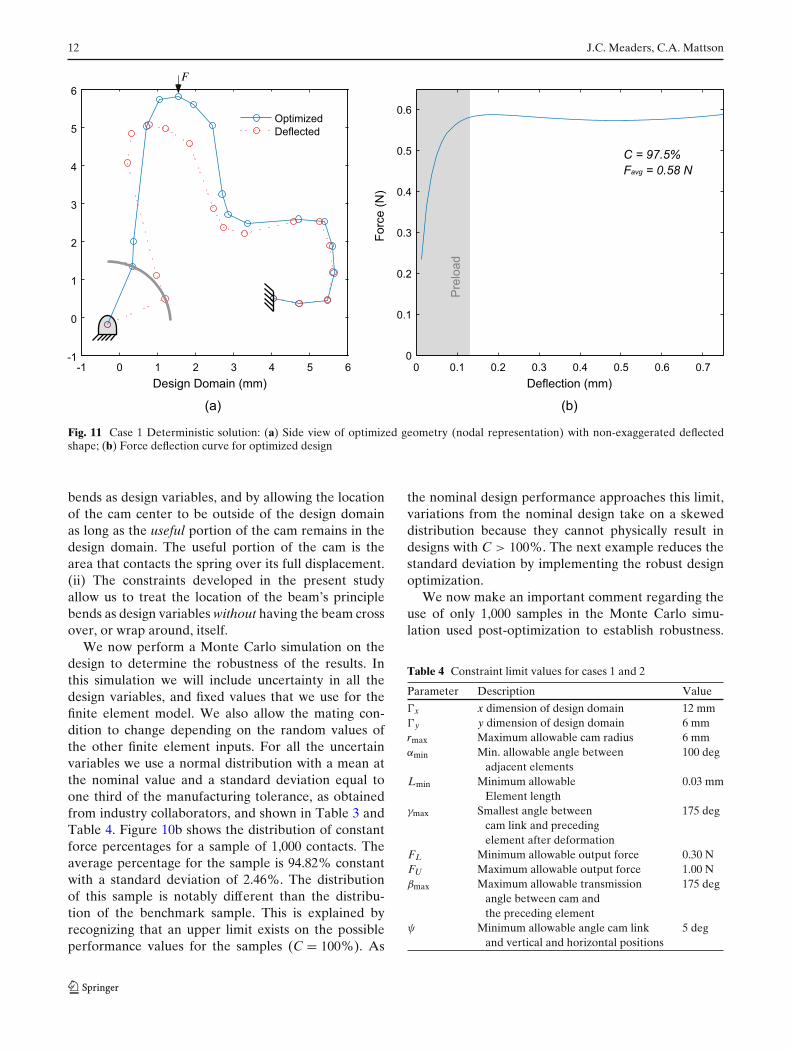
The resulting design in its undeflected and deflectedstate is shown in Fig. 11 with its corresponding force-deflection curve. The percentage of constant force forthis design is 97.50% – a significant increase over our
previous results Weight et al. (2007), which were re-ported as 73.2%. For the deterministic case, we at-tribute the improvement to two key factors: (i) Themodeling approach for spring geometry used hereinsignificantly, and strategically, opens the design spaceto geometries not available in the previous study. Itdoes this by treating the location of the beam’s principle
Table 3 Fixed parameter values for cases 1 and 2
Parameter Description Value
xo x coordinate of fixed point 4.04 mmyo y coordinate of fixed point 0.51 mmxa x coordinate of point where 1.54 mm
force is appliedya y coordinate of point where 5.81 mm
force is appliedn Number of nodes 18E Young’s modulus 110 GPaν Poisson’s ratio 0.34b Cross section width 1.00 mmh Cross section height 0.2 mm� Total deflection range 0.75 mm
including preloadδp Preload deflection 0.11 mmN Safety factor on stress 1.0x Tolerance limit on x 0.03 mmy Tolerance limit on y 0.03 mmE Tolerance limit on E 5.0 GPaν Tolerance limit on ν 0.005b Tolerance limit on b 0.03 mmh Tolerance limit on h 0.03 mmrc Tolerance limit on rc 0.03 mmL Constraint shift needed for 0.06 mm
feasibility of Ld Constraint shift needed for 0.06 mm
feasibility of dR Constraint shift needed for 0.06 mm
feasibility of R
12 J.C. Meaders, C.A. Mattson
-1 0 1 2 3 4 5 6-1
0
1
2
3
4
5
6
F
Design Domain (mm)
Optimized
Deflected
0 0.1 0.2 0.3 0.4 0.5 0.6 0.70
0.1
0.2
0.3
0.4
0.5
0.6
Deflection (mm)
C = 97.5%
Favg = 0.58 N
Fo
rce
(N
)
Pre
loa
d
(a) (b)
Fig. 11 Case 1 Deterministic solution: (a) Side view of optimized geometry (nodal representation) with non-exaggerated deflectedshape; (b) Force deflection curve for optimized design
bends as design variables, and by allowing the locationof the cam center to be outside of the design domainas long as the useful portion of the cam remains in thedesign domain. The useful portion of the cam is thearea that contacts the spring over its full displacement.(ii) The constraints developed in the present studyallow us to treat the location of the beam’s principlebends as design variables without having the beam crossover, or wrap around, itself.
We now perform a Monte Carlo simulation on thedesign to determine the robustness of the results. Inthis simulation we will include uncertainty in all thedesign variables, and fixed values that we use for thefinite element model. We also allow the mating con-dition to change depending on the random values ofthe other finite element inputs. For all the uncertainvariables we use a normal distribution with a mean atthe nominal value and a standard deviation equal toone third of the manufacturing tolerance, as obtainedfrom industry collaborators, and shown in Table 3 andTable 4. Figure 10b shows the distribution of constantforce percentages for a sample of 1,000 contacts. Theaverage percentage for the sample is 94.82% constantwith a standard deviation of 2.46%. The distributionof this sample is notably different than the distribu-tion of the benchmark sample. This is explained byrecognizing that an upper limit exists on the possibleperformance values for the samples (C = 100%). As
the nominal design performance approaches this limit,variations from the nominal design take on a skeweddistribution because they cannot physically result indesigns with C > 100%. The next example reduces thestandard deviation by implementing the robust designoptimization.
We now make an important comment regarding theuse of only 1,000 samples in the Monte Carlo simu-lation used post-optimization to establish robustness.
Table 4 Constraint limit values for cases 1 and 2
Parameter Description Value
�x x dimension of design domain 12 mm�y y dimension of design domain 6 mmrmax Maximum allowable cam radius 6 mmαmin Min. allowable angle between 100 deg
adjacent elementsLmin Minimum allowable 0.03 mm
Element lengthγmax Smallest angle between 175 deg
cam link and precedingelement after deformation
FL Minimum allowable output force 0.30 NFU Maximum allowable output force 1.00 Nβmax Maximum allowable transmission 175 deg
angle between cam andthe preceding element
ψ Minimum allowable angle cam link 5 degand vertical and horizontal positions
Optimization of near-constant force springs subject to mating uncertainty 13
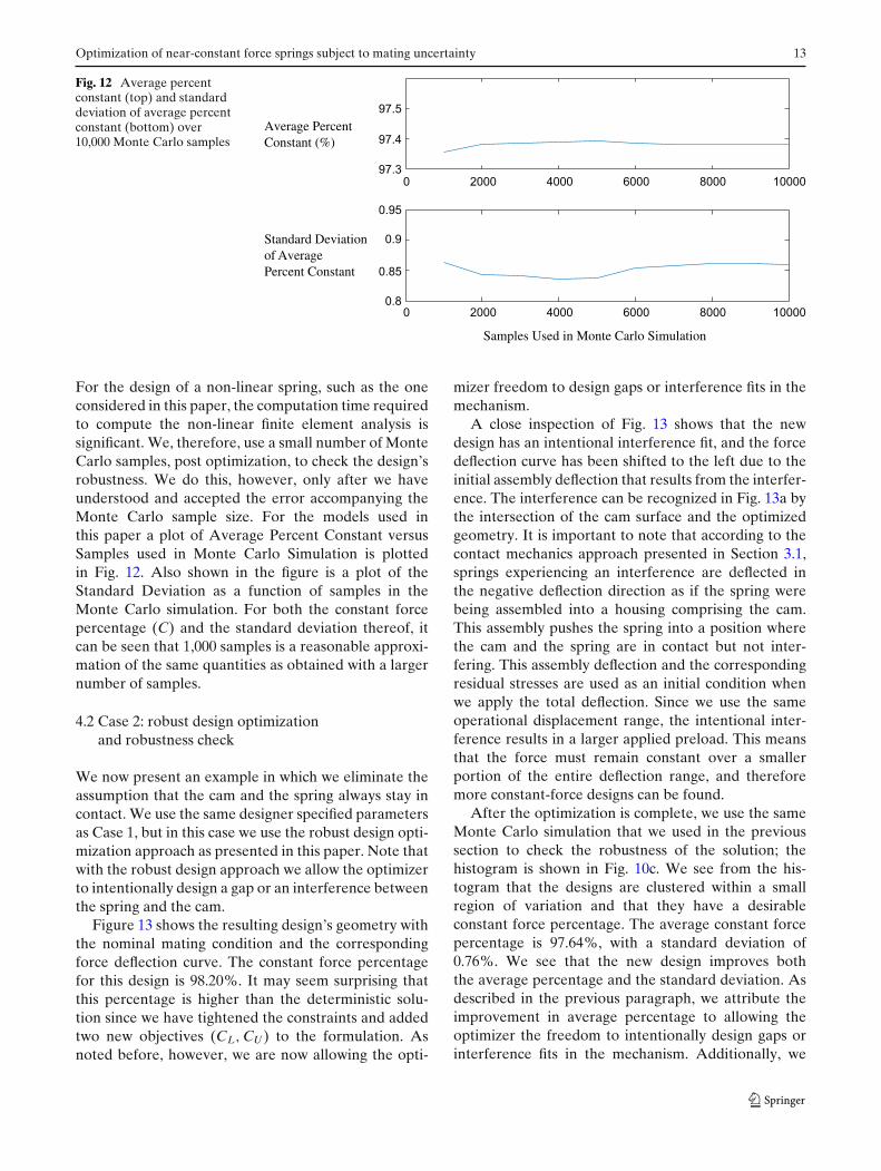
Fig. 12 Average percentconstant (top) and standarddeviation of average percentconstant (bottom) over10,000 Monte Carlo samples
Samples Used in Monte Carlo Simulation
Standard Deviation of Average Percent Constant
Average PercentConstant (%)
97.5
97.4
97.30 2000 4000 6000 8000 10000
0 2000 4000 6000 8000 10000
0.95
0.85
0.9
0.8
For the design of a non-linear spring, such as the oneconsidered in this paper, the computation time requiredto compute the non-linear finite element analysis issignificant. We, therefore, use a small number of MonteCarlo samples, post optimization, to check the design’srobustness. We do this, however, only after we haveunderstood and accepted the error accompanying theMonte Carlo sample size. For the models used inthis paper a plot of Average Percent Constant versusSamples used in Monte Carlo Simulation is plottedin Fig. 12. Also shown in the figure is a plot of theStandard Deviation as a function of samples in theMonte Carlo simulation. For both the constant forcepercentage (C) and the standard deviation thereof, itcan be seen that 1,000 samples is a reasonable approxi-mation of the same quantities as obtained with a largernumber of samples.
4.2 Case 2: robust design optimizationand robustness check
We now present an example in which we eliminate theassumption that the cam and the spring always stay incontact. We use the same designer specified parametersas Case 1, but in this case we use the robust design opti-mization approach as presented in this paper. Note thatwith the robust design approach we allow the optimizerto intentionally design a gap or an interference betweenthe spring and the cam.
Figure 13 shows the resulting design’s geometry withthe nominal mating condition and the correspondingforce deflection curve. The constant force percentagefor this design is 98.20%. It may seem surprising thatthis percentage is higher than the deterministic solu-tion since we have tightened the constraints and addedtwo new objectives (CL, CU ) to the formulation. Asnoted before, however, we are now allowing the opti-
mizer freedom to design gaps or interference fits in themechanism.
A close inspection of Fig. 13 shows that the newdesign has an intentional interference fit, and the forcedeflection curve has been shifted to the left due to theinitial assembly deflection that results from the interfer-ence. The interference can be recognized in Fig. 13a bythe intersection of the cam surface and the optimizedgeometry. It is important to note that according to thecontact mechanics approach presented in Section 3.1,springs experiencing an interference are deflected inthe negative deflection direction as if the spring werebeing assembled into a housing comprising the cam.This assembly pushes the spring into a position wherethe cam and the spring are in contact but not inter-fering. This assembly deflection and the correspondingresidual stresses are used as an initial condition whenwe apply the total deflection. Since we use the sameoperational displacement range, the intentional inter-ference results in a larger applied preload. This meansthat the force must remain constant over a smallerportion of the entire deflection range, and thereforemore constant-force designs can be found.
After the optimization is complete, we use the sameMonte Carlo simulation that we used in the previoussection to check the robustness of the solution; thehistogram is shown in Fig. 10c. We see from the his-togram that the designs are clustered within a smallregion of variation and that they have a desirableconstant force percentage. The average constant forcepercentage is 97.64%, with a standard deviation of0.76%. We see that the new design improves boththe average percentage and the standard deviation. Asdescribed in the previous paragraph, we attribute theimprovement in average percentage to allowing theoptimizer the freedom to intentionally design gaps orinterference fits in the mechanism. Additionally, we
14 J.C. Meaders, C.A. Mattson
-0.1 0 0.1 0.2 0.3 0.4 0.5 0.6 0.7
0
0.1
0.2
0.3
0.4
0.5
0.6
C = 98.2%
Favg = 0.57 N
Preload
Deflection (mm)
-1 0 1 2 3 4 5 6-1
0
1
2
3
4
5
6
Optimized
Deflected
Design Domain (mm)
F
Forc
e (
N)
Fig. 13 Case 2 Robust design solution: (a) Side view of optimized geometry (nodal representation) with non exaggerated deflectedshape; (b) Force deflection curve for optimized design.
attribute the improvement in robustness to the for-mulation of the optimization objective function, whichseeks to improve the constant force percentage for thenominal geometry and seeks to reduce its variationin the presence of known manufacturing tolerances.Notice that all previous studies considered only thenominal geometry case.
Before concluding we must also verify that our ro-bust design optimization solution does not violate ourconstraints when manufactured within our tolerances.The Monte Carlo simulation used earlier is also usedto evaluate the constraints for a sample of contacts.The results confirmed that the original, or unadjusted,constraints are not violated.
5 Concluding remarks
In this paper we have presented a new design strategyfor the design optimization of constant-force electri-cal contacts, which are small scale springs that con-duct electricity. This approach presented in this paperprovides more freedom for the optimization thanthe model used in previously published work (Weightet al. 2007) by giving individual nodes complete free-dom to relocate within the design domain, and byallowing the optimizer to consider intentional gaps andinterferences in the mating of emulated pin-joints. Theimplementation of the improved approach resulted ina significant increase in percentage of constant force.
Using the previously published approach a determin-istic design was found with 73.20% constant force, avalue that was increased to 97.50% by using the newmodel.
We also presented manufacturing uncertainties thatmay be encountered when producing constant-force-electrical contacts, and explored specific situations thatmay alter the mating condition of the contact parts.To control these situations we developed a new modelof the contact, and formulated a design optimizationproblem that not only reduced the variation in per-formance, but increased the performance to 98.20%constant force. This was made possible by allowingthe optimizer to intentionally design for gaps and in-terference fits. It is worth noting that it is completelypossible to design and then manufacture these inten-tional interferences; many connector systems are pre-loaded using intentional interferences between matingparts. This is done by adjusting assembly fixtures so that
Table 5 Comparison of the benchmark, case 1, and case 2 de-signs, with 1,000 Monte Carlo simulation samples (see Table 6for results based on 10,000 samples)
Benchmark Case 1 Case 2(Deterministic) (Robust)
Percent constant 73.20% 97.50% 98.20%force
Average percent 70.24% 94.82% 97.64%constant
Standard deviation 1.68% 2.46% 0.76%
Optimization of near-constant force springs subject to mating uncertainty 15
Table 6 Comparison of the benchmark, case 1, and case 2designs, with 10,000 Monte Carlo simulation samples
Benchmark Case 1 Case 2(Deterministic) (Robust)
Average percent 70.55% 94.61% 97.38%constant
Standard deviation 1.90% 2.60% 0.86%
the placement of the spring in relation to the housingresults in desired interference.
A Monte Carlo simulation has verified that the de-sign identified by the robust design optimization per-formed as expected. The average percentage constantforce for the robust design is 97.64% with a stan-dard deviation of 0.76%. This can be compared tothe Monte Carlo results from the deterministic opti-mization, 94.82% constant with a standard deviationof 2.46%. Table 5 gives a summary of the comparisonbetween these three designs using 1,000 samples inthe Monte Carlo simulation, while Table 6 presentsresults for 10,000 samples. Table 6 is provided to showthat for the mechanism models presented in this paper,1,000 samples is a reasonable number of samples touse, especially when considering the additional com-putational expense that accompanies the use of moresamples.
Acknowledgements The authors gratefully acknowledge thesupport of the Fulton College of Engineering and Technology atBrigham Young University for their support of this project. Theauthors also thank ATL Technology for their practical insight onelectrical connector design, which was generously shared with theauthors.
References
Bhatti M (2006) Advanced topics in finite element analysis ofstructures. John Wiley and Sons, Ch 7
Chen W, Wiecek MM, Zhang J (1999) Quality utility - a com-promise programming approach to robust design. ASME JMech Des 121:179–187
Chen W, Sahai A, Messac A, Sundaraj GJ (2000) Exploringthe effectiveness of physical programming in robust design.ASME J Mech Des 122(2):155–163
Choi JH, Lee SJ, Choi DH (1998) Stochasitic linkage modelingfor mechanical error analysis of planar mechanisms. MechanStruct Mach 26(3):257–276
DeVor RE, Chang T-H, Sutherland JW (1992) Statistical qualitydesign and control: contemporary concepts and methods.Prentice Hall, New Jersey, pp 525–535
Evans MS, Howell LL (1999) Constant-force end-effector mech-anism. In: Proceedings of the IASTED international confer-ence, robotics, and applications, pp 250–256
Frischknecht BD, Howell LL, Magleby SP (2004) Crank-sliderwith spring constant force mechanism. In: Proceedings of theASME design engineering technical conferences, DETC-2004-MECH-57318
Garrett RE, Hall AS (1969) Effect of tolerance and clearance inlinkage design. ASME J Eng Ind 91(1):198–202
Herder JL, van den Berg FPA (2000) Two spatially balancedcompliant mechanisms (SBCM’s), an example and prospec-tus. In: Proceedings of the ASME design engineering techni-cal conferences, DETC-2000-MECH-14120
Howell LL (2001) Compliant mechanisms. John Wiley & Sons,New York, NY
Jenuwine JG, Midha A (1994) Synthesis of single-input andmultiple-output port mechanisms with springs for specifiedenergy absorption. ASME J Mech Des 116(3):937–943
Koch PN (2002) Probabilistic design: optimizing for six sigmaquality. In: AIAA 43rd AIAA/ASME/ASCE/AHS struc-tures, structural dynamics, and materials conference, PaperNumber AIAA–2002–1471
Murphy MD, Midha A, Howell L (1996) The topological syn-thesis of compliant mechanisms. Mech Mach Theory 31(2):185–199
Nathan RH (1985) A constant force generation mechanism.ASME J Mech Transm Autom Des 107:508–512
Nahar DR, Sugar T (2003) Compliant constant-force mechanismwith a variable output for micro/macro applications. In: Pro-ceedings of IEEE international conference on robotics andautomation, vol 1, pp 318–323
Parkinson MB, Howell LL, Cox JJ (1997) A parametric approachto the optimization-based design of compliant mechanisms.In: Proceedings of the ASME design engineering technicalconferences, DETC-1997-DAC-3763
Parkinson A, Sorensen C, Pourhassan N (1993) A general ap-proach for robust optimal design. ASME J Mech Des 115:74–80
Su J, Renaud JE (1997) Automatic differentiation in robustoptimization. AIAA J 35(6):1072–1079
Taguchi G (1986) Introduction to quality engineering. KraussInternational Publications, White Plains, NY
Weight BL (2001) Development and design of constant-forcemechanisms. Master’s thesis, Department of MechanicalEngineering, Brigham Young University, Provo, UT
Weight BL, Magleby SP, Howell LL (2002) Selection of com-pliant constant-force mechanisms based on stress and forcecriteria. In: Proceedings of the ASME design engineeringtechnical conferences, DETC-2002-MECH-34206
Weight BL, Mattson CA, Magleby SP, Howell LL (2007) Con-figuration selection, modeling, and preliminary testing insupport of constant force electrical connectors. ASME JElectron Packag 129(3):236–246