IEEE TRANSACTIONS ON MAGNETICS, VOL. 49, NO. 11, NOVEMBER 2013 5533
Optimized Design of a Novel Modular TubularTransverse Flux Reluctance Machine
Dan-Cristian Popa , Dan D. Micu , Olivia-Ramona Miron , and Loránd Szabó
Department of Electrical Machines and Drives, Technical University of Cluj-Napoca, Cluj-Napoca 400027, RomaniaDepartment of Electrical Engineering, Numerical Methods Research Center, Technical University of Cluj-Napoca,
Cluj-Napoca 400027, Romania
This paper presents a new type of tubular electrical machine with a modular construction. The structure of the machine, concerningits construction, is discussed in the first part of the paper. A semi-analytical method based on the magnetic equivalent circuit calculationis used in order to obtain the flux densities in different parts of the iron core of the machine. A Gauss elimination procedure is appliedto the system of linear equations resulted from the magnetic equivalent circuit, in order to express the flux in the air gap. The problemof optimization of the traction force is analyzed. The maximization of the function is handled with the Nonlinear Conjugate Gradientmethod and verified with a Gauss Newton algorithm. An application of the presented theory shows the usefulness of this approach.The results provided by the optimization method applied on a designed tubular machine illustrate its advantages. A numerical analysisperformed on both a designed and then optimized structure confirmed the results obtained in the optimization process.
Index Terms—Electromagnetic force, gradient method, magnetic circuit, numerical analysis, tubular linear machine.
I. INTRODUCTION
T HE demand for linear servo-controlled high-speed actu-ation, with high precision and a high bandwidth, has in-
creased considerably in the past years [1]. One of the main ad-vantages of the linear electromagnetic machines over their ro-tary-to-linear counterparts is the absence of mechanical gearsand transmission systems, which offers higher performance andimproved reliability [1]. Hence, electrical machines with linearmovement have become more important in common applica-tions such as healthcare [2], [3], transportation [4], [5], and var-ious electrical drives [6].Linear structures present two topologies: flat-type or tubular.
The most important shortcoming of the linear machines with asingle-sided flat-type structure is the existence of a significantthrust force between the two armatures [7]. This disadvantageis avoided due to the radial symmetry of the tubular machinesor the double-sided flat-type structures which determines thecompensation of all the thrust forces acting around the circum-ference of the air gap. The double sided structures require so-phisticated double linear guidance systems, which have to pre-cisely assure the two constant air gaps and also to guide later-ally the moving armature together with the stators. On the otherhand tubular linear motors need only much simpler linear ballor sleeve bearings. Extended researches have been conductedon flat-type or tubular linear structures with permanent mag-nets (PM) [8]–[10]. Despite their very good performances (highpower and force densities, servo characteristics, efficiency) thedrawbacks of such machines, such as the complex manufac-turing and high costs must also be considered [7]. Hence, dif-ferent types of linear machines without permanent magnets (es-pecially those with variable reluctance) can be seen as alterna-tive solutions for different applications. In a former study on
Manuscript received November 11, 2012; revised January 25, 2013 and April19, 2013; accepted June 04, 2013. Date of publication June 18, 2013; date ofcurrent version October 21, 2013. Corresponding author: D.-C. Popa (e-mail:[email protected]).Color versions of one or more of the figures in this paper are available online
at http://ieeexplore.ieee.org.Digital Object Identifier 10.1109/TMAG.2013.2269537
tubular linear reluctance motors, several advantages of tubularvariable reluctance machines have been demonstrated [9]. Aninteresting application of such a machine driving a pump forthe circulatory heart assistance is reported in [2].In this paper, a tubular machine with a modular construction
is proposed. The machine under study originated from the lineartransverse flux reluctance machine with a modular construction.In [12] a flat-type linear transverse flux motor with PM was pre-sented. A simpler structure, without PM, but with similar per-formances, was analyzed in [13]. In [14] the general structure ofthe tubular linear transverse flux reluctance machine has beenstudied. An extended numerical analysis of the tubular motormentioned above was given in [15]. A comparison betweenthe flat type and tubular transverse flux reluctance machines,showing their fault tolerant capacity and the similarities of thetwo structures, was presented in [16]. In [17], the technologiesused for the construction of this tubular motor and the basicconcepts concerning the control of the motor were presented.A prototype of the tubular machine was analyzed and experi-mental tests were performed in [18]. This paper is focused onthe development of an optimized design of the studied tubularmachine. The optimization process is based on the maximiza-tion of the traction force under the assumption that the volumeof the machine remains unchanged.The modular tubular transverse flux reluctance machine
(MTTFRM) operates on the variable reluctance principle andbelongs to the transverse flux machine class. The machine iswithout PM, only with electromagnetic excitation on the statorand passive mover. Its modular construction is presented inthe following sections. A particular feature of both the statorand the mover of the machine is the use of magnetic piecesalternating with non-magnetic spacers.A semi-analytical analysis, based on the magnetic equiva-
lent circuit, is the foundation of the optimization procedure ap-plied for this machine. The force is computed similarly as is inthe case of other devices operating on the variable reluctanceprinciple [7]. The optimization procedure is performed in orderto obtain the maximum traction force. An optimal solution ofthe objective function can be found using the direction of itsgradient. In order to distinguish between the minimum or themaximum of a function, the matrix of second derivatives has to
5534 IEEE TRANSACTIONS ON MAGNETICS, VOL. 49, NO. 11, NOVEMBER 2013
Fig. 1. The structure of the iron core of the proposed MTTFRM.
be investigated. Newton methods, as well as gradient methodsare the classical approach when dealing with this type of prob-lems. Features like search directions and global convergence aretwo main aspects of the optimization [19]. Conjugate gradientmethods include a large number of optimization algorithms withstrong local and global convergence properties [20], [21]. Twogeometric parameters of the machine that influence in differentways the values of the force are considered as variables. The al-gorithm is applied in order to maximize the force developed inthe machine when the exterior dimensions, the length and theexterior diameter, are kept constant.The results of the numerical analysis performed on a designed
and optimized variant are in good agreement with the valuesobtained from the optimization procedure.
II. TRANSVERSE FLUX VARIABLE RELUCTANCE MACHINE
Despite being an old idea, the transverse flux topology wasused again at the beginning of the 1980’s. Most of the studiesfocused on the rotary transverse flux machines as the attentionpaid to the linear variants was much smaller [22].
A. Structure of the Machine
A tubular transverse flux reluctance machine with a modularconstruction has been studied here. The iron core of the machineis presented in Fig. 1 [14].In order to have a continuous movement, the minimum
number of required stator phases is three [15]. A phase ofthe stator of the MTTFRM consists of magnetic pieces,defined as modules or teeth on the axial direction of movement,separated by non-magnetic pieces, named spacers, Fig. 2. Eachmodule of the stator has the poles and slots similar to thestructure of the classic SRM stator, Fig. 3(a) [23]. The moveris passive, and consists of simple cylindrical magnetic pieces,forming the teeth of the mover, alternating with non-magneticspacers. The magnetic pieces of both the stator and the movercan be made either from laminations or from soft magneticcomposites (SMC).The sum of the axial length of a tooth ( on the stator, on
themover) and of a spacer ( on the stator and on themover)is the tooth pitch , Fig. 2. The pole pitch of the stator and mover
Fig. 2. Longitudinal cross-section view of the proposed MTTFRM.
Fig. 3. (a) Transversal section view of the proposed MTTFRM; (b) detail ofhalf of the magnetic piece: (1)—circumferential line in the air gap, (2)—line inradial direction.
must be the same. Furthermore, in [24] it was demonstrated thatfor such variable reluctance linear machines the maximum forceis obtained when the axial lengths of the tooth of the stator andmover are the same . Hence, in all future considerationswe will take into account this hypothesis.In order to work properly as a motor, the modules of the stator
phases have to be shifted by . This shifting is securedby non-magnetic spacers like the ones used between the statormodules, but with adequate axial length, Fig. 2. The step size of
POPA et al.: OPTIMIZED DESIGN OF A NOVEL MODULAR TUBULAR TRANSVERSE FLUX RELUCTANCE MACHINE 5535
the motor is given by the ratio of the tooth pitch and the numberof phases.The windings from the stator are obtained by connecting the
coils of the module of the stator either in series or parallel. Theparallel connection has the advantage because one is obtaininga fault tolerant structure. Concentrated coils around each pole ofthe module are used for the construction of a module winding,Fig. 3(a) [14].When energizing a phase of the modules unaligned with the
corresponding mover magnetic pieces, Fig. 2—phases or ,these tend to align with the stator modules. Thus, only the wind-ings of a single phase have the power supplied during a period,meaning that only the modules of this phase generate tractionforce [14]. The total force is proportional to the number of mod-ules of a phase and the number of poles of a module. From thesereasons the design procedure is focused on obtaining the geo-metric and electric dimensions of a single module for an im-posed traction force [25].The advantages of this topology, in comparison with similar
tubular structures, with or without PM, are:a) the modular structure gives the possibility of an easy as-sembly of the component parts and allows to increase theforce by adding supplementary modules, limited by theimposed length of the machine.
b) simpler structure of the machine and the low cost of itsproduction;
c) the use of spacers that allows reducing the mass;One of the main shortcomings of the MTTFRM is, like in
the case of other transverse flux machines, the high value of theleakage fluxes.
B. Analytical Analysis
The analytical computation has taken into account that thedeveloped force for any linear variable reluctance machine isgiven by the variation of the magnetic energy in the air gapversus the linear displacement, as expressed in (1) [25]. Con-sidering the air-gap magnetic energy as in (2) and the air-gapvolume on the circumference for a phase, as in (3), the forcecan be defined as (4):
(1)
(2)
(3)
(4)
where is the interior radius in the air gap, is the statorpole angle, is the air-gap length, is the shaft radius, as inFig. 3(a), , represent the magnetic energy stored in theair gap for the final and the initial conditions respectively;is the final, respectively the initial axial coordinate, arethe values of the air-gap magnetic flux density in two consecu-tive positions and is the magnetic permeability in the air gap.This equation gives accurate results only for small differencesbetween and .
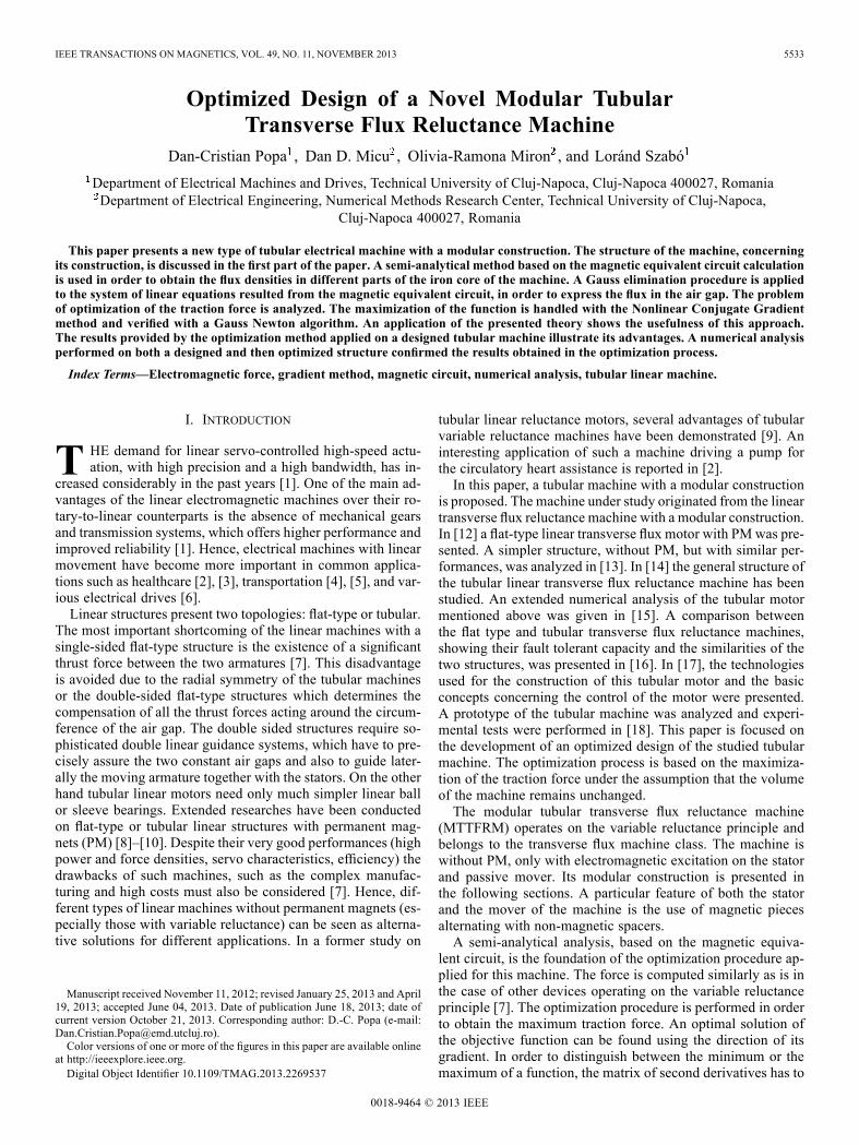
Fig. 4. The reluctance network of a module and the corresponding magneticpart from the mover of the MTTFRM.
The magneto-motive force (mmf) is a function of the airgap and the flux density in the air gap [23].
(5)
where is the value of the air-gap magnetic flux density inthe aligned position having the value imposed at the start of thedesign procedure, and is the saturation factor [25]. Detailsabout this algorithm can be found in [15].The results of the design algorithms were verified first semi-
analytically by using the magnetic equivalent circuit (MEC) ofa module of MTTFRM and the corresponding mover magneticpiece [26]. The first step in obtaining the magnetic equivalentcircuit is to create the reluctance network corresponding to theflux tubes flowing in directions perpendicular to the machineaxis, Fig. 4. This is based on the plausible assumption that al-most all the fluxes flow in radial direction because the axial teethof both the stator and the mover are separated by non-magneticpieces. The only flux in axial direction is given by a part of theleakage fluxes around the coils.The value of is obtained in the design process with (5).
The reluctances: of the yoke , pole , air-gap andmover are computed (6) using the geometric dimensions(stator inner and outer radius, stator pole height, stator poleangle, axial length of a tooth, shaft radius, air gap) that resultedfrom the design procedure and the relative magnetic perme-ability of the iron core material. The leakage reluctancesand are defined considering the paths in the air of theleakage fluxes round the coils and between two neighboringpoles, respectively [23]. All the geometric dimensions are rep-resented in Figs. 2 and 3. The dimensions that were used arerelated to some other geometric dimensions such as: —theinsulation between the coil and the iron core, —distancebetween two neighbored coils, —the medium thickness ofa coil, —the Rogowski coefficient. The most difficult taskis to express the reluctances of the mover and the leakages,
5536 IEEE TRANSACTIONS ON MAGNETICS, VOL. 49, NO. 11, NOVEMBER 2013
Fig. 5. Magnetization curve of the material used for the construction of themagnetic pieces.
mainly due to the necessity of making some approximations ofthe length of the flux paths and the active magnetic surface.
(6)The expression of the reluctance of the air gap depends on
the relative position of the two armatures. Hence, by solving theequations of the magnetic equivalent circuit, different values ofthe fluxes, and consequently of the force, shall be obtained foreach displacement step of the mover with respect to the stator.The values of the relative magnetic permeability in different
parts of the magnetic circuit were computed based on the mag-netization curve of the magnetic material used for the magneticpieces of the machine, given in Fig. 5.Some of the semi-analytical analyses based onMEC take into
account the saturation in different parts of the circuit [27]. Inthis case, based on a simplifying assumption presented below,the flux densities in different parts of the iron core are computedwithout neglecting the saturation level that arises.By considering that variable reluctance machines usually
have a saturated iron core [28], one can apply this concept toMTTFRM as well. In [14], [15] authors show that the variation
of flux density from the center to the exterior of the machine,Fig. 3(c), proves that the poles are highly saturated, while theyoke and the mover are unsaturated. The situation leads tominor changes in different relative positions of the two arma-tures. Hence, it can be said that the values of the flux densitiesin different parts of the iron core of the machine are foundon linear parts of the magnetization curve of the magneticmaterial. Therefore the magnetic permeability in the pole, yokeand mover respectively can be considered constant; and hencethe corresponding reluctances can be easily computed.Due to the necessity to take into consideration the influence
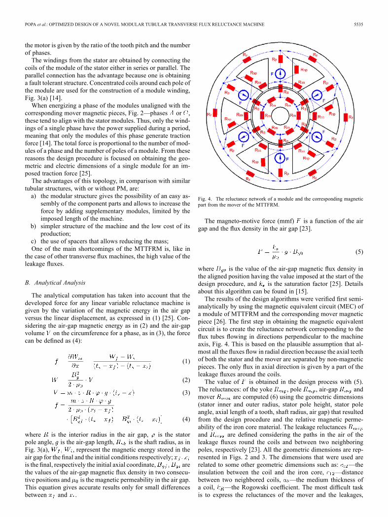
of each pole on its neighbors, the resulting magnetic equivalentcircuit is rather complex, Fig. 6.In order to compute the flux density values in different parts
of the machine, one must solve the system of equations asso-ciated with this magnetic equivalent circuit. These equationswere obtained by applying the Kirchhoff’s laws to the magneticequivalent circuit.The variables in the linear system of equations defined above
are the fluxes: through the air-gap , through the poles ,through yoke , through mover and the leakage onesand .
(7)
The flux density in the air-gap , which is the ratio betweenthe flux through the air-gap and the air-gap surface, can beexpressed analytically, as a function of the mmf and of thereluctances in the circuit. Generally, this can be developed asthe function of the mmf, geometric dimensions and magneticpermeability in various parts of the machine. The expressionfor was computed from (7) by means of a Gauss eliminationtechnique.By computing the traction force with (4), where the fluxes
in two consecutive positions were obtained from (8), shown atthe bottom of the page, resulted in the general expression of themedium value of the force over a certain interval. The precisionof the estimated force increases as the considered interval issmaller.
C. Application
The main parameters of a designed MTTFRM are given inTable I. Steel 111 XC was used for the construction of the ironcore.The computed values of the flux densities in different parts
of the machine for the aligned position of the armatures usingMEC are given in Table II.The maximum force computed by using (4) is 165.43 N. This
value can be maximized, considering the exterior dimensions
(8)
POPA et al.: OPTIMIZED DESIGN OF A NOVEL MODULAR TUBULAR TRANSVERSE FLUX RELUCTANCE MACHINE 5537
Fig. 6. Magnetic equivalent circuit of a module and the corresponding magnetic part from the mover of the MTTFRM.
TABLE IIMPOSED AND COMPUTED VALUES AT THE DESIGNED MTTFRM
constant and by applying the optimization procedures that willbe described in the next section.
D. Numerical Analysis
The performances of electromagnetic devices can be verifiedby means of numeric computation (the finite element methodFEM). The commercial package Flux 3D is used.
TABLE IIVALUES OF THE FLUX DENSITY IN DIFFERENT PARTS OF THE MTTFRM
OBTAINED FROM ANALYTICAL ANALYSIS IN ALIGNED POSITION
The numerical analysis was focused on the flux densitydistribution and the force developed in the machine. Although2D analysis would be much simpler, requiring a less complexmodel, less time and less computer resources, the structure ofthe MTTFRM can be modeled only by using a 3D analysis[22]. This is due to the flux paths that are perpendicular tothe direction of movement. The software gives the possibilityto construct a parameterized geometry of the model. In thenumerical analysis, performed in the ‘magneto-static’ moduleof Flux 3D, a displacement step of 0.5 mm between the relativepositions of the two armatures was considered. These are thesame conditions like those considered in the semi-analyticalanalysis where we have obtained different values of the forcefor each relative position of the mover with respect to the stator.Two major issues must be considered when creating the anal-
ysis model. As mentioned in previous sections and underlinedby formula (4), the force is proportional to the number of mod-ules of a phase and the number of poles of a module. By takinginto consideration the radial symmetry of theMTTFRM, the nu-merical model can be reduced to a single pole of a stator module,the neighboring slots and the corresponding mover part, Fig. 7.The total force was calculated as being equal to the product
between the value obtained in the simulation, the number ofpoles of a module and the number of modules of a phase. Forthis machine the multiplying factor is 12.The mesh of the model, Fig. 8, had 107,464 nodes and
633,783 volume elements. The percentage of excellent qualityelements was 63.37%, while the percentage of poor quality
5538 IEEE TRANSACTIONS ON MAGNETICS, VOL. 49, NO. 11, NOVEMBER 2013
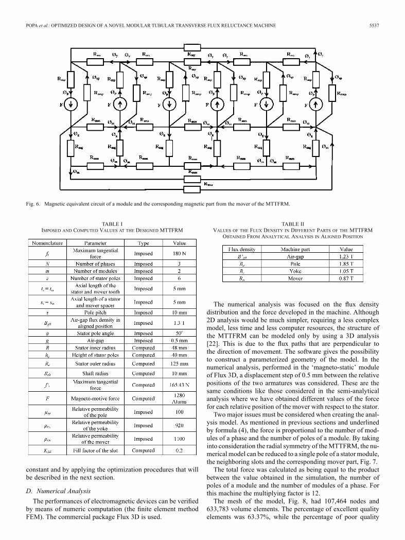
Fig. 7. 3D model of the MTTFRM created for the numerical analysis (the coilwound on the pole is not shown).
Fig. 8. Mesh of the 3D model of the analyzed MTTFRM.
Fig. 9. Flux density map in the pole of a module and the corresponding statoryoke and mover part in the aligned position.
elements was 0.59%. These values assured fairly accurateresults.The flux density map in the structure is presented in Fig. 9.
The plots confirm that the pole was saturated, while the yokeand the mover had the flux density values significantly reduced.The flux density in the air gap evidences a good accordance
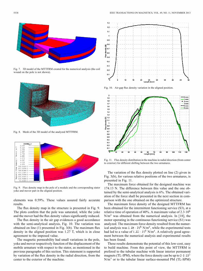
with the semi-analytical analysis, Fig. 10. The variation wasobtained on line (1) presented in Fig. 3(b). The maximum fluxdensity in the aligned position was 1.27 T, which is in closeagreement to the imposed value.The magnetic permeability had small variations in the pole,
yoke and mover respectively function of the displacement of themobile armature with respect to the stator, as mentioned in theprevious paragraphs of this section. This statement is supportedby variation of the flux density in the radial direction, from thecenter to the exterior of the machine.
Fig. 10. Air-gap flux density variation in the aligned position.
Fig. 11. Flux density distribution in the machine in radial direction (from centerto exterior) for different shifting between the two armatures.
The variation of the flux density plotted on line (2) given inFig. 3(b), for various relative positions of the two armatures, ispresented in Fig. 11.The maximum force obtained for the designed machine was
174.13 N. The difference between this value and the one ob-tained by the semi-analytical analysis is 6%. The obtained vari-ation of the force shall be presented in the next section in com-parison with the one obtained on the optimized structure.The maximum force density of the designed MTTFRM has
been obtained for the intermittent functioning service (S3), at arelative time of operation of 40%. A maximum value of 2.3 10N/m was obtained from the numerical analysis. In [18], themotor operating in the continuous functioning service (S1) wasanalyzed. The maximum force density resulted from the numer-ical analysis was N/m , while the experimental testshad led to a value of N/m . A relatively good agree-ment between the numerical analysis and experimental resultshas been found.These results demonstrate the potential of this low-cost, easy
to build machine. From this point of view, the MTTFRM isprefered to the tubular machine with linear interior permanentmagnets (TL-IPM), where the force density can be up toN/m or to the tubular linear surface-mounted PM (TL-SPM)
POPA et al.: OPTIMIZED DESIGN OF A NOVEL MODULAR TUBULAR TRANSVERSE FLUX RELUCTANCE MACHINE 5539
motors where values of N/m have been determined[29].
III. OPTIMIZATION PROBLEM
The goal of the optimization procedure was to obtain a max-imized value for the traction force under the assumption that allthe exterior geometric dimensions, as well as the stator innerradius, were kept constant. The traction force is in fact an elec-tromagnetic force. Due to this aspect, in this case, the use of theterm electromagnetic force was more appropriate.The expression of the force evidenced that some of the geo-
metric parameters, like the axial length of a tooth (module),greatly influence its value. The variation of the force for thistype of machine on half of the pole pitch is almost sinusoidal[7], [28].The problem of maximizing the value of the electromagnetic
force obtained with (4) was subjected to an optimization pro-cedure. The expression for the force is nonlinear and thereforeadequate nonlinear methods were used in order to perform theoptimization of the machine with respect to its geometrical di-mensions. The force formula (4) was rewritten in terms of theoptimization parameters (the axial length of a tooth and the shaftradius) (9).
(9)
The fluxes through the air-gap in two consecutive positions,and , were computed with (9). and were the
active surfaces of the air-gap in the considered positions.In order to optimize the value of the developed force in
a preset interval, certain relative positions of the mover tothe stator must be considered. Consequently, we obtained anoverdetermined nonlinear system with three equations andone unknown . The method of nonlinear least squaresis the classical approach when dealing with a parameterizedapplication [30].A nonlinear overdetermined system of equations can be
written:
(10)
where . Solving a nonlinear system where multiple so-lutions exist is complicated and has high computational com-plexity [31].The aim was to find the vector of the unknown parameters
such that the function fits best the given data, i.e., the objectivefunction is maximized. This occurs when the gradient ofis equal to zero.The solution of the optimal parameters can be found by
solving the normal equations:
(11)
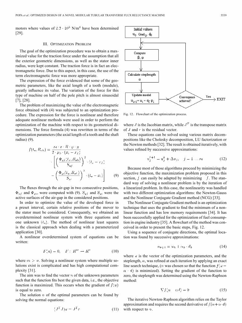
Fig. 12. Flowchart of the optimization process.
where is the Jacobian matrix, while is the transpose matrixof and is the residual vector.These equations can be solved using various matrix decom-
positions like the Cholesky decomposition, LU factorization orthe Newtonmethods [32]. The result is obtained iteratively, withvalues refined by successive approximations:
(12)
Because most of those algorithms proceed by minimizing theobjective function, the maximization problem proposed in thissection, can easily be adapted by minimizing . The stan-dard way of solving a nonlinear problem is by the iteration ofa linearized problem. In this case, the nonlinearity was handledwith two different optimization algorithms: the Newton-Gaussand the Nonlinear Conjugate Gradient method (NCG) [33].The Nonlinear Conjugate Gradient method is an optimization
technique that uses the gradient to find the minimum of a non-linear function and has low memory requirements [34]. It hasbeen successfully applied for the optimization of fuel consump-tion in engine industry [35]. A flowchart of the method was con-ceived in order to present the basic steps, Fig. 12.Using a sequence of conjugate directions, the optimal loca-
tion was found by successive approximations:
(14)
where is the vector of the optimization parameters, and thesteplength, , was refined at each iteration by applying an exactline search technique, ( was chosen so that the function
is minimized). Setting the gradient of the function tozero, the steplength was determined using the Newton-Raphsonmethod:
(15)
The iterative Newton-Raphson algorithm relies on the Taylorapproximation and requires the second derivative ofwith respect to .
5540 IEEE TRANSACTIONS ON MAGNETICS, VOL. 49, NO. 11, NOVEMBER 2013
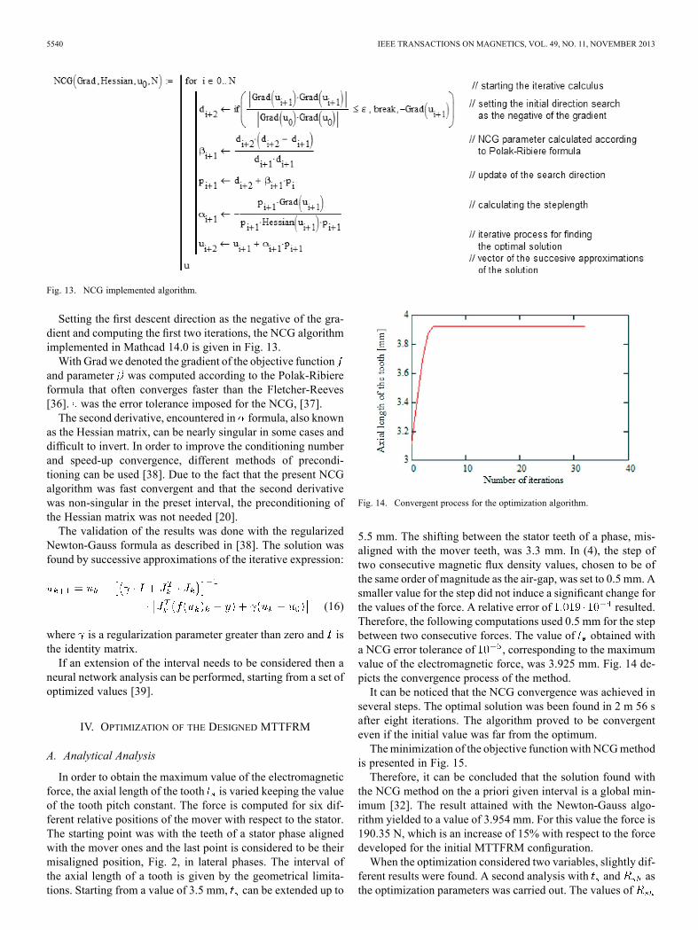
Fig. 13. NCG implemented algorithm.
Setting the first descent direction as the negative of the gra-dient and computing the first two iterations, the NCG algorithmimplemented in Mathcad 14.0 is given in Fig. 13.With Gradwe denoted the gradient of the objective function
and parameter was computed according to the Polak-Ribiereformula that often converges faster than the Fletcher-Reeves[36]. was the error tolerance imposed for the NCG, [37].The second derivative, encountered in formula, also known
as the Hessian matrix, can be nearly singular in some cases anddifficult to invert. In order to improve the conditioning numberand speed-up convergence, different methods of precondi-tioning can be used [38]. Due to the fact that the present NCGalgorithm was fast convergent and that the second derivativewas non-singular in the preset interval, the preconditioning ofthe Hessian matrix was not needed [20].The validation of the results was done with the regularized
Newton-Gauss formula as described in [38]. The solution wasfound by successive approximations of the iterative expression:
(16)
where is a regularization parameter greater than zero and isthe identity matrix.If an extension of the interval needs to be considered then a
neural network analysis can be performed, starting from a set ofoptimized values [39].
IV. OPTIMIZATION OF THE DESIGNED MTTFRM
A. Analytical Analysis
In order to obtain the maximum value of the electromagneticforce, the axial length of the tooth is varied keeping the valueof the tooth pitch constant. The force is computed for six dif-ferent relative positions of the mover with respect to the stator.The starting point was with the teeth of a stator phase alignedwith the mover ones and the last point is considered to be theirmisaligned position, Fig. 2, in lateral phases. The interval ofthe axial length of a tooth is given by the geometrical limita-tions. Starting from a value of 3.5 mm, can be extended up to
Fig. 14. Convergent process for the optimization algorithm.
5.5 mm. The shifting between the stator teeth of a phase, mis-aligned with the mover teeth, was 3.3 mm. In (4), the step oftwo consecutive magnetic flux density values, chosen to be ofthe same order of magnitude as the air-gap, was set to 0.5 mm. Asmaller value for the step did not induce a significant change forthe values of the force. A relative error of resulted.Therefore, the following computations used 0.5 mm for the stepbetween two consecutive forces. The value of obtained witha NCG error tolerance of , corresponding to the maximumvalue of the electromagnetic force, was 3.925 mm. Fig. 14 de-picts the convergence process of the method.It can be noticed that the NCG convergence was achieved in
several steps. The optimal solution was been found in 2 m 56 safter eight iterations. The algorithm proved to be convergenteven if the initial value was far from the optimum.Theminimization of the objective function with NCGmethod
is presented in Fig. 15.Therefore, it can be concluded that the solution found with
the NCG method on the a priori given interval is a global min-imum [32]. The result attained with the Newton-Gauss algo-rithm yielded to a value of 3.954 mm. For this value the force is190.35 N, which is an increase of 15% with respect to the forcedeveloped for the initial MTTFRM configuration.When the optimization considered two variables, slightly dif-
ferent results were found. A second analysis with and asthe optimization parameters was carried out. The values of
POPA et al.: OPTIMIZED DESIGN OF A NOVEL MODULAR TUBULAR TRANSVERSE FLUX RELUCTANCE MACHINE 5541
Fig. 15. The minimization of the objective function using NCG method.
Fig. 16. Force variation on half of the pole pitch for various lengths of the axialtooth obtained from numerical analysis.
were considered to be between 6 and 14 mm. An optimum so-lution was found when is 11.2 mm. The resulting valuewas 3.871 mm. The electromagnetic force was 193.91 N. Thedifference between the optimization with one and two parame-ters was less than 1%.
B. Numerical Analysis
In the numerical analysis, in order to obtain the maximumvalue of the developed force an interval between 3.5 and 5.5mm, with a step of 0.25 mm, was considered for the value ofthe axial length of a tooth, Fig. 16. The major shortcoming en-countered in this analysis was the fact that the optimal value,which corresponds to the maximum force, is usually skippeddue to the practical impossibility of taking into account all thevalues in the considered interval.A numerical analysis can provide only the interval where the
maximum force can be found. The maximum value of the forcewas obtained for different shifting of the teeth of the two ar-matures when different values of the axial length of a toothwere considered.When this value was increased due to a smallershifting between the teeth, a lower force resulted.The maximum value of the force was obtained for an axial
length of the tooth of 3.75 mm and it was 202.2 N. A differenceof 15.9% with respect to the initial designed variant resulted.A conclusion of this numerical analysis is that the maximumvalue of the electromagnetic force can be obtained for a valueof between 3.75 mm and 4 mm.
Fig. 17. Force variation on half of the pole pitch for the initial and optimizedmachine obtained from numerical analysis.
The optimization procedure developed with the NCG algo-rithm gave a value of 3.925 mm for the axial length of the teeth;this value corresponds to the maximum force [40]. A numer-ical analysis was carried out in this situation as well. In Fig. 17a comparison of the forces between the initial and optimizeddesign is presented. The maximum force developed by the op-timized MTTFRM was 204.66 N and represents an increase of17.5% with respect to the value obtained from numerical anal-ysis for the initial variant. A small difference between the forcevalues of the analytical optimization and the numerical anal-ysis resulted. It is very important to underline that the maximumvalue of the force was obtained in both cases for the same axiallength of the tooth.The value of the axial length of the tooth greatly influenced
the developed force. However, the value of the shaft radius af-fected only the mover reluctance, so its influence on the perfor-mance of themachine should be smaller. The numerical analysisconsidered values between 6 and 14 mm for the shaft radius,with a step of 1 mm. The maximum force of 205.3 N was ob-tained for a shaft radius of 11 mm and it was slightly larger thanfor the initial shaft radius. This value was close to that obtainedfrom the optimization procedure.The maximum force density of the optimized MTTFRM was
obtained, as in the case of the initial variant, when the motorwould operate in an intermittent functioning service (S3) at arelative time of operation of 40%. The obtained value ofN/m confirms the increase of force computed by numericalmeans.
V. CONCLUSION
The present paper deals with the optimization of a new typeof tubular machine with a modular construction. The basicconcepts of the configuration of the design were presented.A semi-analytical analysis based on the magnetic equivalentcircuit method was carried out and the results were in a goodagreement with the imposed design data. The developed forcewas expressed as a function of the flux densities obtained fromthe system of equations associated with the magnetic equiv-alent circuit. The expression of the force depends on certaingeometric parameters and was subjected to an optimization
5542 IEEE TRANSACTIONS ON MAGNETICS, VOL. 49, NO. 11, NOVEMBER 2013
procedure. The nonlinear conjugate gradient algorithm wasused to maximize the electromagnetic force in the MTTFRM.The machine with the optimized value of the axial length of
the tooth was numerically analyzed using Flux 3D. A satisfac-tory agreement between the numerical analysis and the valuesobtained with NCG resulted.An optimized MTTFRM is under construction. Further work
is focused on the validation of the numerical optimized resultswith experimental data.
ACKNOWLEDGMENT
This work was supported by a grant of the Romanian NationalAuthority for Scientific Research, CNDI-UEFISCDI, projectnumber PCCA191/2012.
REFERENCES
[1] J. Wang, G. W. Jewell, and D. Howe, “A general framework for theanalysis and design of tubular linear permanent magnet machines,”IEEE Trans. Magn., vol. 35, no. 3, pt. 2, pp. 1986–2000, May 1999.
[2] N. Martinez, P. Leprince, and B. Nogarede, “A novel concept of pul-satile magnetoactive pump for medical circulatory support,” in ICEMElect. Mach., 2008, pp. 1–6.
[3] M. Watada, K. Yanashima, Y. Oishi, and D. Ebihara, “Improvement oncharacteristics of linear oscillatory actuator for artificial hearts,” IEEETrans. Magn., vol. 29, no. 11, pp. 3361–3363, Nov. 1993.
[4] J. Wang, W. Wang, and K. Atallah, “A linear permanent-magnet motorfor active vehicle suspension,” IEEE Trans. Veh. Technol., vol. 60, no.1, pp. 55–63, Jan. 2011.
[5] J. Wang, D. Howe, and Z. G. Lin, “Comparative studies on linear motortopologies for reciprocating vapor compressors,” in 2007 IEEE Int.Electric Machines Drives Conf., 2007, vol. 2, pp. 364–369.
[6] C. Henaux, B. Nogarede, and D. Harribey, “A new concept of mod-ular permanent magnet and soft magnetic compound motor dedicatedto widespread application,” IEEE Trans. Magn., vol. 48, no. 6, pp.2035–2043, Jun. 2012.
[7] I. Boldea, Linear Motion Electromagnetic Devices. New York, NY,USA: Taylor & Francis, 2001.
[8] H. Chang-Chou, L. Ping-Lun, and L. Cheng-Tsung, “Optimal designof a permanent magnet linear synchronous motor with low coggingforce,” IEEE Trans. Magn., vol. 48, no. 2, pp. 1039–1042, Feb. 2012.
[9] B. L. J. Gysen, K. J. Meessen, J. J. H. Paulides, and E. A. Lomonova,“3-D analytical and numerical modeling of tubular actuators withskewed permanent magnets,” IEEE Trans. Magn., vol. 47, no. 9, pp.2200–2212, Sep. 2011.
[10] C. Urban, R. Gunther, T. Nagel, R. Richter, and R.Witt, “Developmentof a bendable permanent-magnet tubular linear motor,” IEEE Trans.Magn., vol. 48, no. 8, pp. 2367–2373, Aug. 2012.
[11] B. Tomczuk and M. Sobol, “Field analysis of the magnetic systems fortubular linear reluctance motors,” IEEE Trans. Magn., vol. 41, no. 4,pp. 1300–1305, Apr. 2005.
[12] D. C. Popa, L. Szabo, and V. Iancu, “Linear transverse flux motor forconveyors,” in Proc. 6th Int. Symp. Linear Drives for Industrial Appli-cation (LDIA), Lille, France, 2007, paper no. 188, on CD.
[13] D. C. Popa, L. Szabo, and V. Iancu, “Improved design of a lineartransverse flux reluctance motor,” in Proc. 11th Int. Conf. Optimiza-tion of Electrical and Electronic Equipment (OPTIM’2008), Braşov,Romania, 2008, pp. 136–141.
[14] D. C. Popa, L. Szabo, V. I. Gliga, and V. Iancu, “Design of noveltubular transverse flux reluctance machine,” in Proc. 8th Int. Symp.Linear Drives for Industrial Application (LDIA), Eindhoven, Nether-lands, 2011, paper no. 183, on CD.
[15] D. C. Popa, V. I. Gliga, L. Szabo, and V. Iancu, “Tubular transverseflux variable reluctance motor in modular construction,” in Proc.13th Int. Conf. Optimization of Electrical and Electronic Equipment(OPTIM’2012), Braşov, Romania, 2012, pp. 572–577.
[16] V. Iancu, D. C. Popa, and L. Szabo, “Fault tolerant modular lineartransversal flux reluctance machines,” J. Comput. Sci. Control Syst.,pp. 1–4, 2009, Romania.
[17] V. I. Gliga, D. C. Popa, and V. Iancu, “Modular transversal fluxtubular machine—Presentation and progress achievements,” Annalsof the University of Craiova, 2011, pp. 1–6, Electrical Engineeringseries, No. 35, ISSN 1842-4805.
[18] D. C. Popa, V. I. Gliga, and L. Szabo, “Theoretical and experimentalstudy of a modular tubular transverse flux reluctance machine,” Progr.Electromagn. Res., vol. 139, pp. 41–55, 2013.
[19] C. Gilbert and J. Nocedal, “Global convergence properties of conjugategradients methods for optimization,” SIAM. J. Optim., vol. 2, no. 1, pp.21–42, 1992.
[20] W. W. Hager and H. Zhang, “A survey of nonlinear conjugate gradientmethods,” Pacific J. Optim., no. 2, pp. 35–58, 2006.
[21] Z. Badics and Z. J. Cendes, “A Newton Raphson algorithm with adap-tive accuracy control based on a block-preconditioned conjugate gra-dient method,” IEEE Trans. Magn., vol. 41, no. 5, pp. 1652–1655, Sep.2005.
[22] J. Chang, D. H. Kang, I. A. Viorel, and L. Strete, “Transverse flux reluc-tance linear motor’s analytical model based on finite-element methodanalysis results,” IEEE Trans. Magn., vol. 43, no. 4, pp. 1201–1204,Apr. 2007.
[23] R. Krishnan, Switched Reluctance Motor Drives—Modeling, Sim-ulation, Analysis, Design, and Applications, Industrial ElectronicsSeries. Boca Raton, FL, USA: CRC Press, 2001.
[24] P. Acarnely, Stepping Motors: A Guide to Theory and Practice.Stevenage, Herts, U.K.: IET, 2002.
[25] I. A. Viorel, K. Hameyer, and L. Strete, “Transverse flux tubularswitched reluctance motor,” in Proc. 11th Int. Conf. Optimizationof Electrical and Electronic Equipment (OPTIM 2008), Braşov,Romania, 2008, pp. 131–136.
[26] J. K. Kim, S. W. Joo, S. C. Hahn, J. P. Hong, D. H. Kang, and D.H. Koo, “Static characteristics of linear BLDC motor using equivalentmagnetic circuit and finite element method,” IEEE Trans. Magn., vol.40, no. 2, pp. 742–745, Mar. 2004.
[27] H. Gholizad, B. Funieru, and A. Binder, “Direct modeling of motionaleddy currents in highly saturated solid conductors by the magneticequivalent circuit method,” IEEE Trans. Magn., vol. 45, no. 3, pp.1016–1019, Mar. 2009.
[28] G. Henneberger and I. A. Viorel, Variable Reluctance Electrical Ma-chines. Aachen, Germany: Shaker Verlag, 2001.
[29] N. Bianchi, S. Bolognani, D. D. Corte, and F. Tonel, “Tubular linearpermanent magnet motors: An overall comparison,” IEEE Trans. Ind.Appl., vol. 39, no. 2, Mar./Apr. 2003.
[30] R. V. Dukkipati, Numerical Methods. New Delhi, India: New AgeInternational (P) Limited, 2010.
[31] J. Nocedal and S. J. Wright, Numerical Optimization. New-York:Springer-Verlag, 1999.
[32] Y. Zhan and A.M. Knight, “Parallel time-stepped analysis of inductionmachines with Newton-Raphson iteration and domain decomposition,”IEEE Trans. Magn., vol. 44, no. 6, pp. 1546–1549, Jun. 2008.
[33] O.-R. Miron, D. Desideri, D. D. Micu, A. Maschio, A. Ceclan, andL. Czumbil, “Estimation of an equivalent short solenoid model usingdifferent numerical methods,” Arch. Elect. Eng., vol. 60, no. 4, pp.433–444, 2011.
[34] K. Preis, O. Biro, M. Friedrich, A. Gottvald, and C. Magele, “Compar-ison of different optimization strategies in the design of electromag-netic devices,” IEEE Trans. Magn., vol. 27, no. 5, pp. 4154–4157, Sep.1991.
[35] A. Kakaee and M. Kesshavarz, “Comparison the sensitivity analysisand conjugate gradient algorithms for optimization of opening andclosing angles of valves to reduce fuel consumption in XU7/L3engine,” Int. J. Autom. Eng., vol. 2, no. 3, 2012.
[36] A. Neculai, “Scaled memoryless BFGS preconditioned conjugate gra-dient algorithm for unconstrained optimization,” Optim. Meth. Softw.,vol. 2, pp. 561–571, 2007.
[37] J. Trzasko and A. Manduca, “Highly undersampled magnetic reso-nance image reconstruction via homotopic -minimization,” IEEETrans. Med. Imag., vol. 28, no. 1, pp. 106–121, 2009.
[38] A. V. Knyazev, “Toward the optimal preconditioned eigensolver: Lo-cally optimal block preconditioned conjugate gradient method,” SIAMJ. Sci. Comput., vol. 23, no. 2, pp. 517–541, 2001.
[39] D. D. Micu, L. Czumbil, G. Christoforidis, and A. Ceclan, “Layer re-current neural network solution for an electromagnetic interferenceproblem,” IEEE Trans. Magn., vol. 47, no. 5, pp. 1410–1413, May2011.
[40] Y. H. Dai and Y. Yuan, “An efficient hybrid conjugate gradient methodfor unconstrained optimization,” Ann. Oper. Res., no. 103, pp. 33–47,2001.