9


CStatic
Var
Compensator
1 2
44
TCR Reactor
Control and Protection System11
Capacitor BankFilter Reactor
66
Thyristor Valve22
Valve Cooling System
33
SVC Transformer55
77
●OPTIMIZED SVC SYSTEM DESIGN
●HIGH QUALITY AND RELIABILITY
●EASY MAINTENANCE
●LIGHT TRIGGERED THYRISTOR
●FLEXIBLE DIGITAL CONTROLLER
TMT&D provides SVC systems with superior features;
Power System
SVC SYSTEM
Valve Cooling System
Control andProtection System
SVC BUS
11 66 6655
55
22
33
44
Substation Facilities
77
77

Typical Configurations
General PerformanceIt is essential to balance the supply and demand of active and reactive power in an electrical power system. If the balance is lost, system frequency and voltage excursions may occur resulting, in the worst case, in the collapse of the power system. Appropriate voltage and reactive power control is one of the most important factors for stable power system operation. The Static Var Compensator (SVC) is one of the advanced power electronics equipment which provides fast and continuous capacitive and inductive reactive power supply to the power system.
The SVC typically consists of a TCR (Thyristor Controlled Reactor), a TSC (Thyristor Switched Capacitor) and Fixed capacitors (FC) in a harmonic filter arrangement as shown in Figure 1. The TCR consists of reactors and thyristor valves. The TCR continuously controls reactive power by varying the current amplitude flowing through the reactors. The TSC consists of capacitors, reactors and thyristor valves. The TSC switches on and off the capacitors. The AC filters provide fixed reactive power and absorb the harmonic current generated by the TCR.The TCR+FC is the most basic configuration of the SVC.The TCR+TSC+FC, the more advanced configuration, can be tuned to minimize the losses at the most frequent operation point.
Operation PrincipleTCR (Thyristor Controlled Reactor)The amplitude of the TCR current can be changed continuously by varying the thyristor firing angle (Figure2). The firing anglecan be varied from 90 degrees to 180 degrees. The TCR firing angle can be fully changed within one cycle of the fundamental frequency, thus providing smooth and fast control of reactive power supply to the system.
Figure 1 Typical Configuration of SVC
TSC (Thyristor Switched Capacitor)The TSC is used to switch on and off the capacitor bank. The TSC does not generate any harmonic current components. The capacitor switching operation is completed within one cycle of the fundamental frequency. The TSC provides a faster and more reliable solution to capacitor switching than conventional mechanical switching devices(Figure 3). The TSC can operate in coordination with the TCR so that the sum of the reactive power from the TSC and the TCR becomes linear. Applications with only TSC's are also available, providing stepwise control of capacitive reactive power.
FC (Fixed capacitors)AC Filters are used to reduce the harmonics injected into the power system by TCR operation. AC filters also provide a certainamount of capacitive reactive power.
Figure 2 TCR Current and firing angle
Figure 3 TSC Current and firing angle
……………………………�
……………………………�
〈TCR+FC〉� 〈TCR+TSC+FC〉�
TCR FC TCR TSC
FC
Power transfer capacity increase
Reactive Power
Compensation
Three-phase voltage
balancing
Voltage regulationTransient
stability improvement
Power oscillation damping
Steady-state stability
improvement FlickerSuppression
Line loss minimization
SVC
CStatic
Var
Compensator
3 4

Flexible Digital Control SystemTMT&D provides a digital controller as part of the SVC system. The digital controller utilizes multiple 32bit Central Processing Units (CPU) and high precision Digital Signal Processors (DSP) to control the thyristor valves in both the TCR and TSC. The digital control system also controls various other AC system equipment. The all-digital technology offers high flexibility, reliability, simple and easy maintenance.
Easy Parameter Adjustment
Reliable Software Configuration
Power System Simulator
The controller unit includes a control panel with an LCD display.Through the control panel and the LCD display engineering personnel can read measured values and manipulate the controller parameters. The controller can also be accessed remotely, through a communication port.
TMT&D has a sophisticated power system simulator, which enables real-time, high precision dynamic simulation of large power systems. Upon request, the SVC controller performance can be examined in detail using the simulator.Digital simulators are also available and are recommended for reduced scale power systems.
SVC System EngineeringTMT&D designs SVC systems utilizing the best engineering practices and a vast amount of experience. TMT&D provides all of the studies necessary for the SVC system design and offers the best solution to customers.
Control and Protection Design
●Configuration of Control and Protection Design●Control Functions
●Transient Capability Check
Hardware Design●SVC Layout●Civil Design
System Planning
●Optimum Installation Location●System Capacity
System Design
●SVC Configuration
●Harmonics distortion Limit
●Loss and Cost Evaluation
●Equipment Rating
・Rating Calculation・Harmonic Current Calculation・Filter Design Calculation・Insulation Coordination
・Over Current Analysis
・Dynamic Behavior Analysis
・Drawings
・Load Flow Analysis・Stability Analysis
All of the control functions are implemented through the software installed in the controller. The control software is easily modified with the specialized development tool. This software development tool (PE-CASE) consists of the WindowsTM based control block diagram drawing function and automatic software code generation function.The control block diagram drawn on a Personal Computer running a WindowsTM
operating system can be automatically coded into object files and loaded into the CPU or the DSP without software errors. TMT&D provides the PE-CASE control software development tool and the training course as part of the SVC controller package to enable the customer to do future control system and parameter modifications.
・System Harmonic Impedance Calculation
SVC Terminal Voltage
Arrester Currents
AC Filter Inrush Current
SVC Performance Analysis Power swing suppression effect
25.0
25.0
(μS)
(μS)
(mS) 100.0
(kA
)
4.0
4.0
0.0
0.0
0.0
-4.0
400.0
Vol
tage
(kV
)C
urre
nt (
kA)
CStatic
Var
Compensator
5 6

Direct Light Triggered Thyristor ValveTMT&D pioneered the application of direct Light Triggered Thyristor (LTT) technology to high power electronic valves. The first commercial installation of an LTT valve for SVC was completed in 1984. Since then, TMT&D has provided LTT valves for numerous facilities throughout the world.
Reduction Number of Parts Reliability Improvement
Easy Maintenance
The conventional Electrically Triggered Thyristor (ETT) requirescomplicated electronic circuits in the triggering system. The thyristortriggering electronic circuits require a large number of parts for each thyristor valve. Thyristor triggering circuitry has to be insulated to the valve voltage in relation to ground potential. Contrary to the ETT, the LTT can be fired directly through the optical fibers requiring lesscomplicated triggering circuitry and no high voltage insulation(Figure 4).
The reduction in number of parts results in higher reliability of the valve (Figure5). LTT valves have reliability twice that of the ETTvalves.
Figure 5 Reliability Comparison of valves
Figure 6 Valve (Water) Cooling System
Figure 4 Number of parts in a valve
〈Conventional ETT System〉�〈Applied LTT System〉�
Operation Flexibility ImprovementThe power for triggering of the LTT valve is provided from the DCpower supply. The LTT valve operation is therefore not affectedduring prolonged power system faults. Contrary to the LTT, the ETT valve requires auxiliary power to generate firing signal at the thyristor level. The auxiliary power is usually obtained from the voltage across the thyristor element. The ETT valve operation is therefore restricted at the SVC start-up and during prolonged power system faults.
Electromagnetic noiseimmunity improvementOptical signals used for triggering of the LTT valve have inherentimmunity to electromagnetic noise. In contrast, the ETT valve requires countermeasures against electromagnetic noise.
Reliable Firing System
Valve Cooling System
The optical triggering system is based on the branched light guidesand duplicated Laser Diodes (LD) or Light Emitting Diodes (LED).Two high power triggering LD's or LED's are connected to each LTT. In the event of a failure of one of the two LD's or LED's, the LD or LTT can be triggered by the remaining LD or LED.
Excess heat generated in the thyristor valves is removed by thecooling system. Due to the high efficiency, the water cooling system(Figure 6) is applied to large capacity valves. A forced air cooling system is applied to small capacity valves. TMT&D has installedcooling systems for SVC valves in many different environments.
Water cooling system has following advantages;■Compact design■Maximization of thyristor current capability■Small auxiliary losses
Item ETT LTTInspection parts 100% Approx. 30%Maintenance time 100% Approx. 30%Maintenance interval 100% Approx. 200%Maintenance cost 100% Approx. 15%
ETT valveLTT valve
Valve failure level
Sou
nd th
yris
tors
(%)
100
95
90
0 10 20 30 40 50
Operating duration(year)
LTT ValveLTT; Light Triggered ThyristorLG; Light GuideLED; Light Emitting DiodePG; Pulse Generator
L; ReactorR1, C1, R2; Voltage Grading Circuit
(b)LTT valve
PG
LG
LG
LG
LG
L
L
LTT
LTT
LTT
LTT
R1
R1
C1
C1
R2
R2
LED LED LED LED
Main circuit
Monitoring circuit
Firing circuit }�Thyristorlevelelectronics
ETT LTTvalve valve
100
Num
ber
of p
arts
(%)
The elimination of gate electronics circuitry offers great advantagesin maintenance. Since no complicated electronic circuitry is locatedat the thyristor level, the maintenance becomes very simple and is reduced to the inspection of a small number of parts in the thyristorvalve.A comparison in valve maintenance time and cost between ETT andLTT is shown below.
ETT ValveETT; Electrically Triggered Thyristor
PC; Power CircuitL/E; Light/Electric Converter
L; ReactorR1, C1, R2; Voltage Grading Circuit
AMP; Gate electronics
L
L
ETT
ETT
ETT
PC
PC
PC
AMP
AMP
PCAMP
AMP
L/E
L/E
L/E
L/ELG
LG
LG
LED LED LED LED
R1R2
C1
R1R2
C1
PG
(a)ETT valve
LG; Light Guide
LED; Light Emitting DiodePG; Pulse Generator
CStatic
Var
Compensator
7 8

Other Equipment
Transformer
TCR Reactor
AC Filter Bank
Switchgear
A step-down transformer is usually placed between the AC system busbar and the low voltage busbar to which the thyristor valves are connected. Once the SVC capacity is determined, the best way to design the valve is to use the thyristor current capability at its maximum. Then, the minimum necessary AC voltage is derived to obtain the given capacity. The AC voltage across the thyristor valve determines the number of thyristors in the valve and consequently the valve cost. The step-down transformer adjusts the AC voltage for the minimum system cost.The transformer increases the thyristor valve efficiency.
The TCR reactor generates inductive reactive power of the SVC. Air core reactors are most commonly applied; however, oil filled iron core reactors may be supplied if reguired. The inductance value of reactors is custom designed for each system in order to satisfy the specified reactive power output.
AC filter banks provide capacitive reactive power and absorb the harmonic currents generated by the TCR. The AC filter banks are carefully designed considering the harmonics environment in the AC system.
The switchgear is necessary to connect or disconnect the SVC to or from the AC system. TMT&D is one of the major suppliers of both gas and air insulated switchgear.
Quality Control SystemAs a Japanese manufacturer famous worldwide for their high quality, TMT&D established an effective quality control system. The quality control system has been proven to comply with the requirements of the ISO 9000 standards.
Manufacturing
System Design and EngineeringOptimum SVC System is designed for each project.
Factory testsValve and controller are fully tested.
Site TestsPerformance tests are carried out combining●all controllers and protection devices and ●all AC and DC auxiliary equipment.
Approval of ISO9001/ISO14001TMT&D was one of the first companies to conform to ISO9001, an international standard for quality assurance.To further improve reliability and protect the environment, TMT&Dcontinues to utilize leading edge technology and facilities to maximize quality and efficiency, and to meet the requirements ofenvironmental standards ISO14001.Caring for and protecting the global environment, guided by themotto "creating a Human and Earth friendly Environment ", TMT&Dis engaged in a wide range of activities to minimize the use ofchemical substances and to save energy.
CStatic
Var
Compensator
9 10
11 12
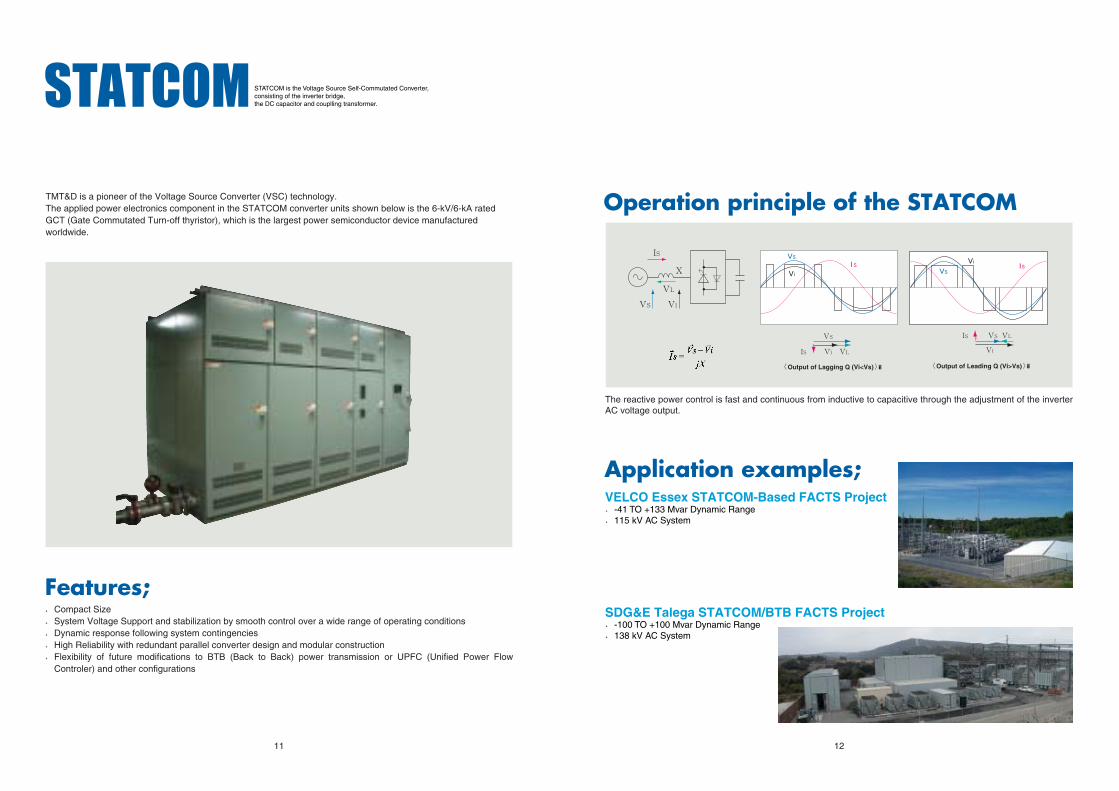
Operation principle of the STATCOM
Application examples;
The reactive power control is fast and continuous from inductive to capacitive through the adjustment of the inverter AC voltage output.
〈Output of Lagging Q (Vi<Vs)〉� 〈Output of Leading Q (Vi>Vs)〉�
VELCO Essex STATCOM-Based FACTS Project●-41 TO +133 Mvar Dynamic Range●115 kV AC System
SDG&E Talega STATCOM/BTB FACTS Project●-100 TO +100 Mvar Dynamic Range●138 kV AC System
STATCOM is the Voltage Source Self-Commutated Converter, consisting of the inverter bridge, the DC capacitor and couplling transformer.
TMT&D is a pioneer of the Voltage Source Converter (VSC) technology.The applied power electronics component in the STATCOM converter units shown below is the 6-kV/6-kA rated GCT (Gate Commutated Turn-off thyristor), which is the largest power semiconductor device manufactured worldwide.
Features;●Compact Size●System Voltage Support and stabilization by smooth control over a wide range of operating conditions●Dynamic response following system contingencies●High Reliability with redundant parallel converter design and modular construction●Flexibility of future modifications to BTB (Back to Back) power transmission or UPFC (Unified Power Flow
Controler) and other configurations

Voltage Control
Power Oscillation Damping
Overvoltage Suppression
Voltage Stabilization
Relocatable SVC
275kV,230MVA SVC, �Queensland Australia�-80MVA(inductive) to �+150MVA(capacitive)� consists of TCR+FC
regulates and controls the 275kV system voltage at the set point under steady state and contingency conditions.
275kV,300MVA SVC, �South Australia�-140MVA(inductive) to �+160MVA(capacitive)� consists of TCR+TSC
regulates the 275kV bus voltage, improves the system stability and damps the power oscillation.
400kV,580MVA SVC, �Austria�-580MVA(500ms)(inductive)� consists of TCR
suppresses overvoltages generated at the HVDC converter load rejection.
500kV,100MVA SVC, �Tokyo Japan�-20MVA(inductive) to �+80MVA(capacitive)� consist of TCR+FC
stabilizes 500kV voltage on a major powertransmission system.
500kV,50MVA � STATCOM�Nagano JapanA large capacity STATCOM of 50MVA had been operated successfully since October 1992 at Shin-Shinano Substation in Japan.
-40MVA(inductive) SVC,�Osaka Japan
A relocatable SVC is transported by a trailer to the installation site.
TMT&D has supplied various types of SVC systems custom designed for specific installation conditions and requirements. Some of different designs and applications are shown.
13 14

12-1, Toranomon 3-chome, Minatoku, Tokyo 150-0001, JapanHomepage: www.tmt-d.com <http://www.tmt-d.com>
MITSUBISHI ELECTRIC POWER PRODUCTS, INC.530 Keystone Drive Ð HQ Building
Warrendale, PA 15086 USATelephone: 724-778-5111
Homepage: www.meppi.com <http://www.meppi.com>
[Other locations]ARGENTINA, AUSTRALIA, BRAZIL, CHINA, HONG KONG, INDIA,
KUWAIT, SAUDI ARABIA, SINGAPORE, TAIWAN, U.A.E., U.K.
TMT&D is a joine venture of Toshiba and Mitsubishi Electric.The data given in this brochure are subject to change without notice. 30617-1 03-12T40


