Optimizing Your Stations Optimizing Your Stations Performance Performance A few hints / techniques, recommendations for getting the most RF out to the Antenna from your HF, VHF / UHF station. Tonights Presenters: Tonights Presenters: Doug Theriault – NO1D Doug Theriault – NO1D John Laing - K7PRS John Laing - K7PRS
Transcript
Optimizing Your Stations Optimizing Your Stations PerformancePerformance
A few hints / techniques, recommendations for getting the most RF out to the Antenna
● New to ham radio, building station perhaps for first time● Wondering whether signal could be improved. How do I
measure performance of station, what tools or components?● Few thoughts, perhaps a better understanding of how to
optimize RF getting to the antenna with less loss.
● Suggestions from two OLD Hams wanting to share their experience.
● Briefly touching many topics, these can be expanded upon as a separate future presentation if there is interest.
● YARC has a Very Strong Elmer Group willing to assist you in building out a top notch station or debugging problems.
AgendaAgenda
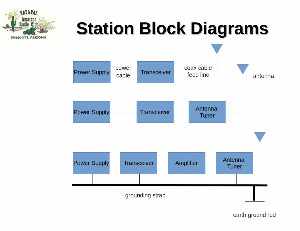
● Station Components– Basic block diagrams
● Power Supply and RF Grounding● Antenna and SWR ● Transmission Lines
– Quality of Connections
● Measuring and Measurement Tools● Understanding Loss
– Basic concept of Decibels
Station ComponentsStation Components
● Power Supply– Mains based, 110v to 12v, Linear/Switched
– Ground System
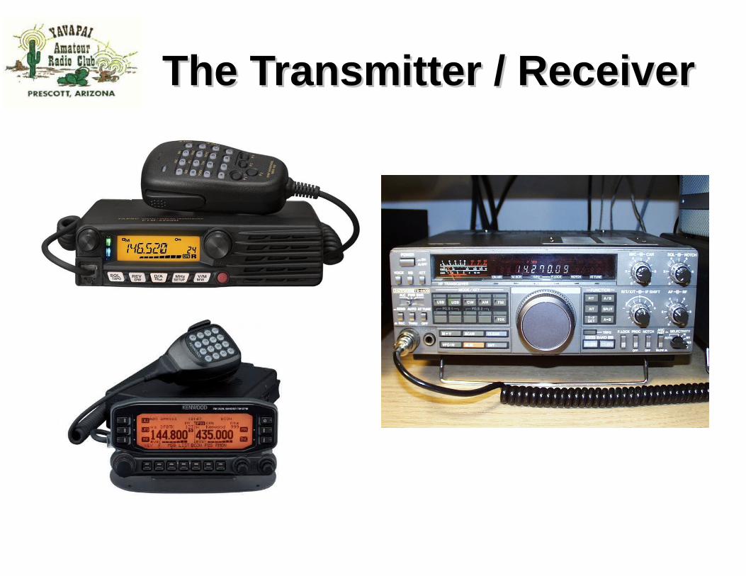
● Transceiver– HF, VHF, UHF or beyond– New or Old
– Perhaps Home Brew !
● Antenna– Rubber Ducks, Verticals, Dipoles, Yagi’s, loops and more
● Feed Line / Transmission Line– Coaxial cables, Open Feed Lines– Connectors, PL-259, N, SMA and others
– Coaxial Switches
Station Block DiagramsStation Block Diagrams
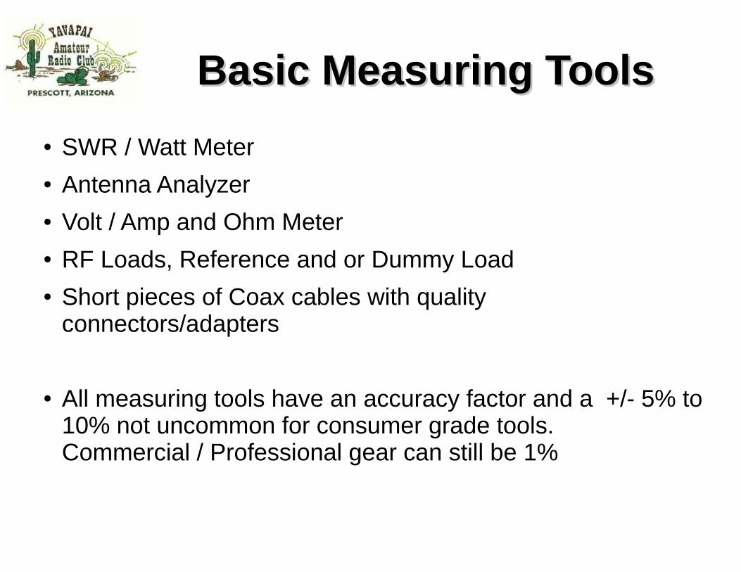
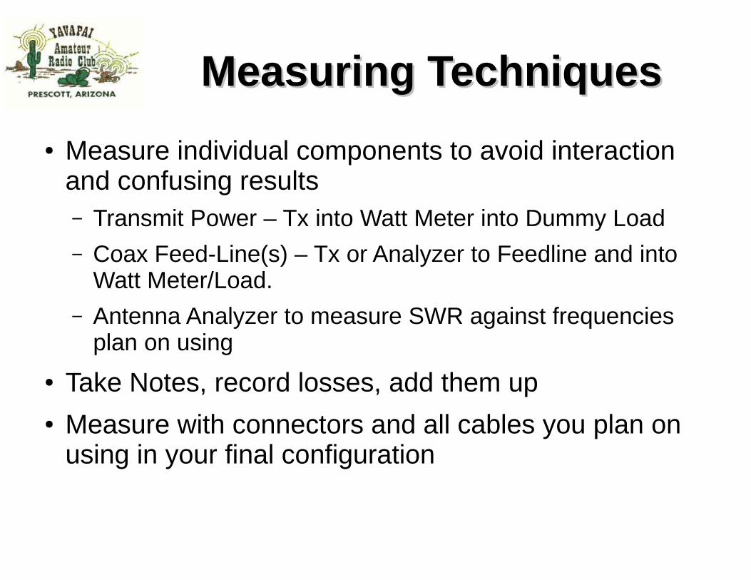
Basic Measuring ToolsBasic Measuring Tools
● SWR / Watt Meter● Antenna Analyzer● Volt / Amp and Ohm Meter● RF Loads, Reference and or Dummy Load● Short pieces of Coax cables with quality
connectors/adapters
● All measuring tools have an accuracy factor and a +/- 5% to 10% not uncommon for consumer grade tools. Commercial / Professional gear can still be 1%
Volt Meter / Amp MeterVolt Meter / Amp Meter
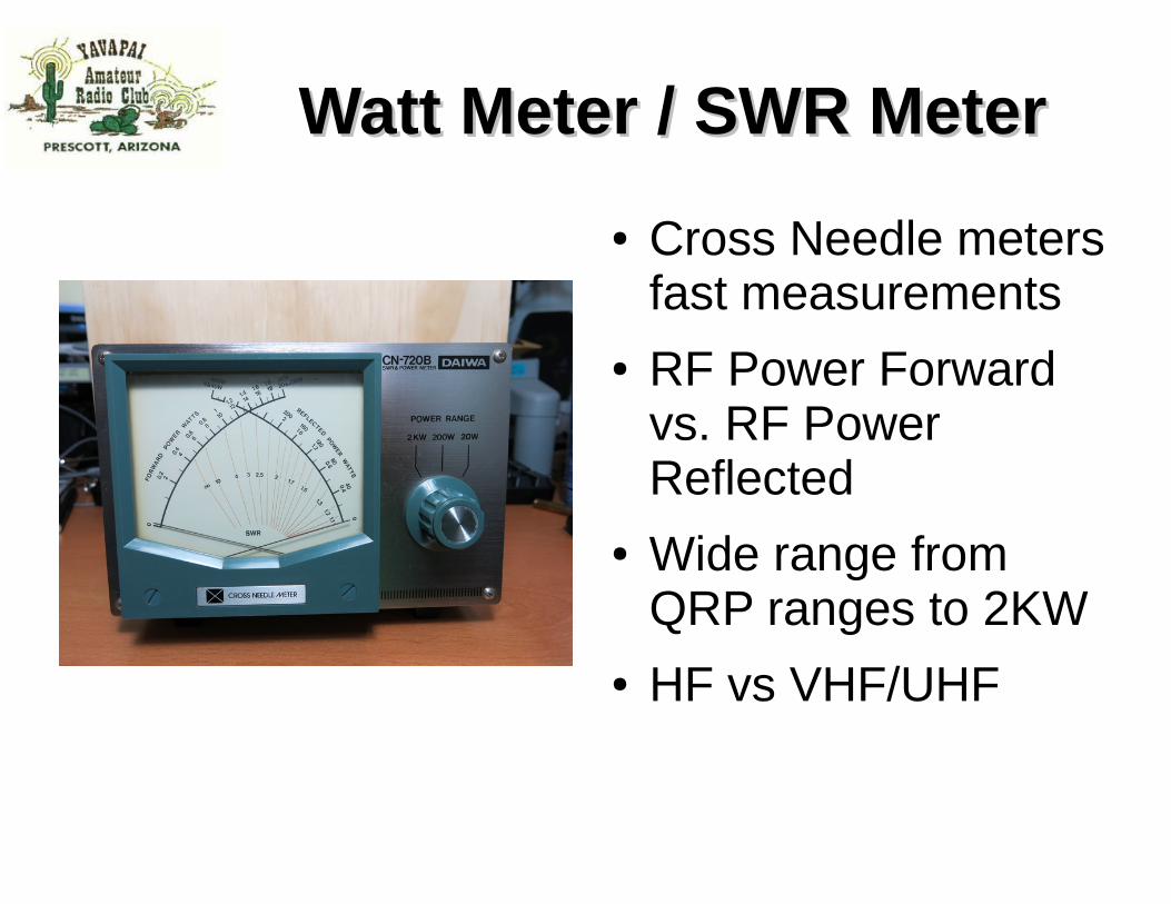
Watt Meter / SWR MeterWatt Meter / SWR Meter
● Cross Needle meters fast measurements
● RF Power Forward vs. RF Power Reflected
● Wide range from QRP ranges to 2KW
● HF vs VHF/UHF
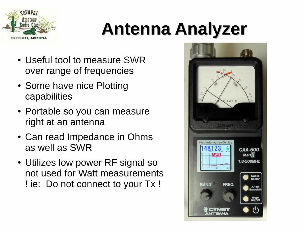
Antenna AnalyzerAntenna Analyzer
● Useful tool to measure SWR over range of frequencies
● Some have nice Plotting capabilities
● Portable so you can measure right at an antenna
● Can read Impedance in Ohms as well as SWR
● Utilizes low power RF signal so not used for Watt measurements ! ie: Do not connect to your Tx !
RF LoadsRF Loads
● Precision 50 ohm loads● With or Without
Metering● Can operate over very
wide frequency range● Dummy loads are very
useful to test without an Antenna
Equipment Age ConsiderationsEquipment Age Considerations
● Electronic Components age● Performance of components can degrade over
time● Old Coax, weathered Coax
– cuts in coax, breaks, water intrusion
● Poor Connections – tarnish / oxidization
– soldering or crimp quality
● Capacitors are big culprit● Semi-conductors typically do not degrade, they
Fail and stop working.● Tubes however can degrade with age● Solder or Crimp connections can break down
due to stress, heat
● Be forewarned buying old gear, esp rigs 20+yrs or older
● Old gear is great, you just might need to upgrade components before putting it on the air
● Old Microphones, elements can impact your audio quality
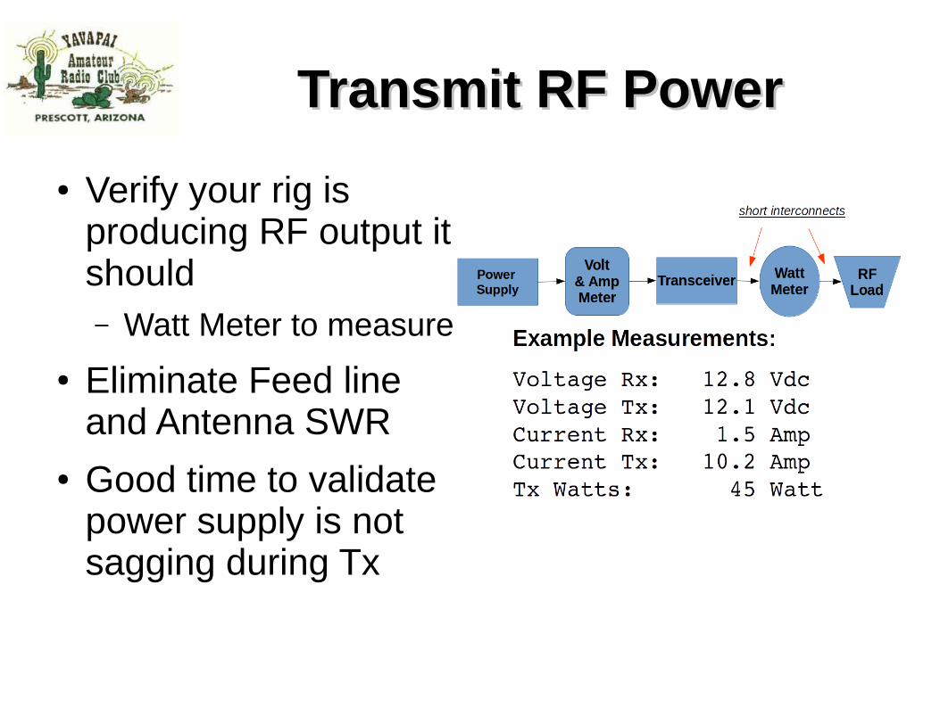
The Transmitter / ReceiverThe Transmitter / Receiver
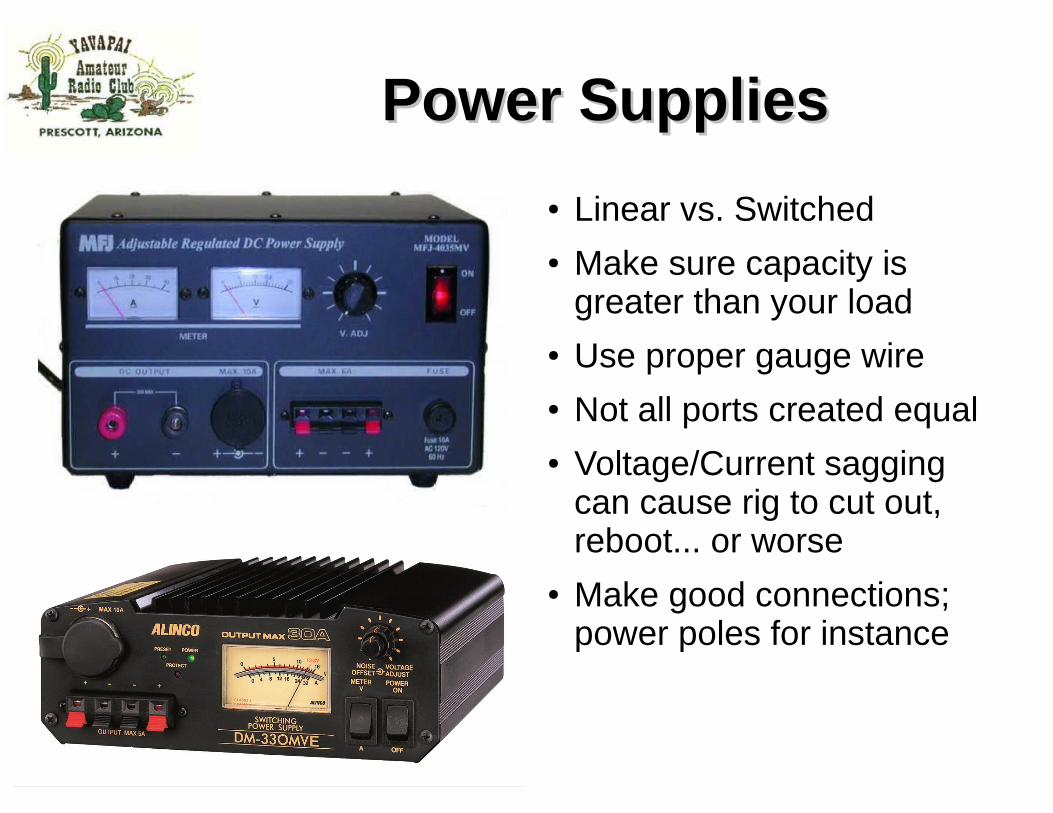
Power SuppliesPower Supplies
● Linear vs. Switched● Make sure capacity is
greater than your load● Use proper gauge wire● Not all ports created equal● Voltage/Current sagging
can cause rig to cut out, reboot... or worse
● Make good connections; power poles for instance
GroundingGrounding
● Lightning protection● Electrical Safety
● RF Ground– Especially important for certain
types of antenna– ¼ λ Verticals, end fed long
wires, unbalanced– Helps eliminate common mode
currents, RFI, noise from ground loops
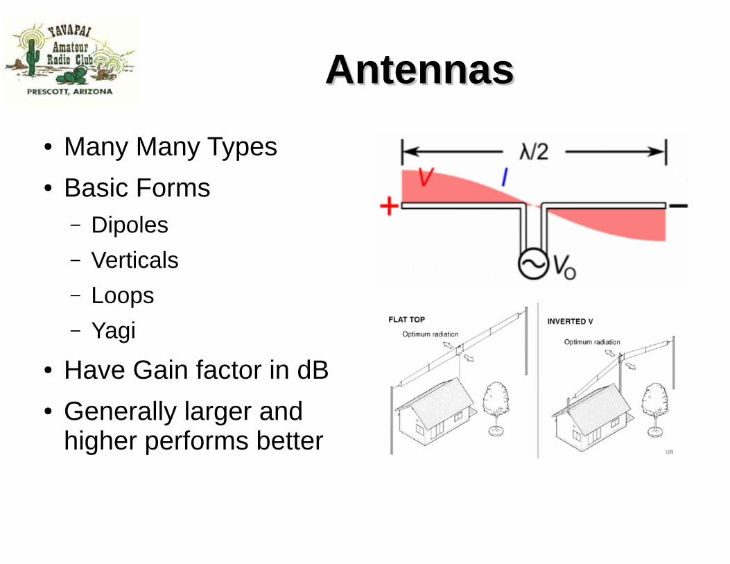
AntennasAntennas
● Many Many Types● Basic Forms
– Dipoles
– Verticals– Loops– Yagi
● Have Gain factor in dB● Generally larger and
higher performs better
High Frequency - HFHigh Frequency - HF
● Height above ground for Dipoles varies w/ frequency; higher is better
● Dipole Element Lengths– cut elements accurately
● Pattern and performance can be impacted by placement to nearby metal objects
● Low dipoles can help optimize signals within 600 mi.
● Verticals can lower the take off angle of RF on lower frequencies, 160m/80m for instance for greater distance
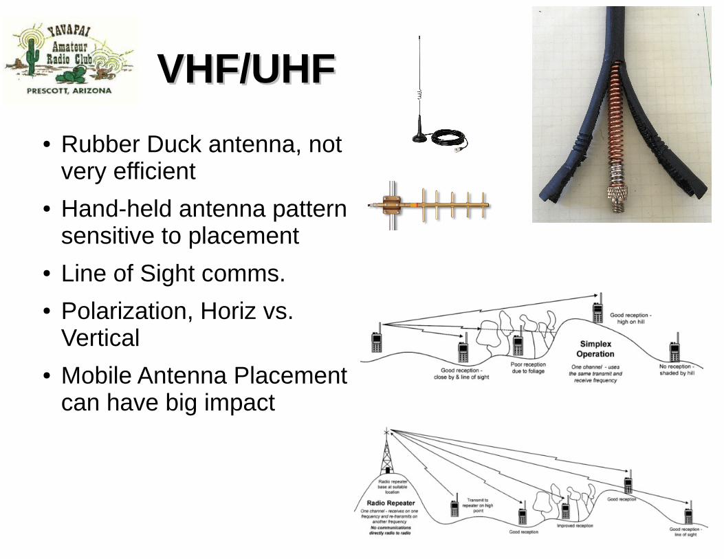
VHF/UHFVHF/UHF
● Rubber Duck antenna, not very efficient
● Hand-held antenna pattern sensitive to placement
● Line of Sight comms.● Polarization, Horiz vs.
Vertical● Mobile Antenna Placement
can have big impact
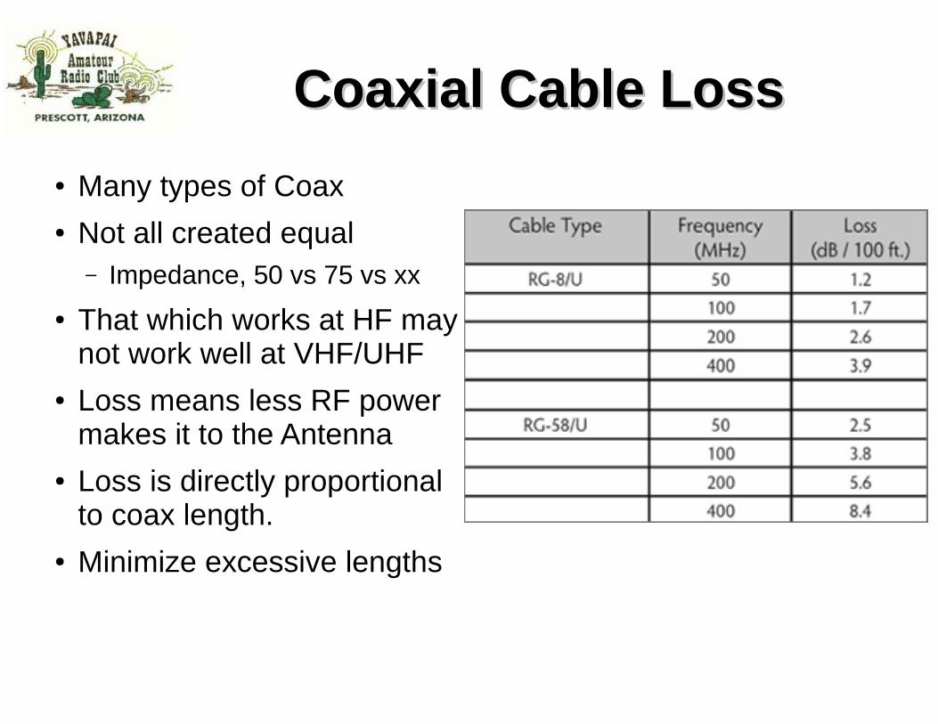
Coaxial CableCoaxial Cable
● Most common feed line
● Easy to use● Not affected by
nearby materials● Has higher loss than
open-wire line at most frequencies
● Air-insulated “hard line” has lowest loss
Cheap versions of coax have braid that has been reduced to the point that any bend can cause a gap in the braid. This results in RF leaking and loss.
2014 Technician License Course
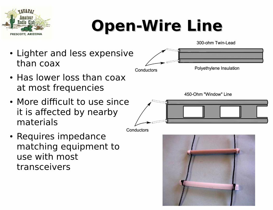
Open-Wire LineOpen-Wire Line
● Lighter and less expensive than coax
● Has lower loss than coax at most frequencies
● More difficult to use since it is affected by nearby materials
● Requires impedance matching equipment to use with most transceivers
● That which works at HF may not work well at VHF/UHF
● Loss means less RF power makes it to the Antenna
● Loss is directly proportional to coax length.
● Minimize excessive lengths
Hard-line CoaxHard-line Coax
● For very long runs of coax
● Used at repeater sites
● and very large antenna installations
● Lower loss factor
Low Loss Coax – Yikes !Low Loss Coax – Yikes !
Double Shielded RG-214/UDouble Shielded RG-214/U
● Reduces RF leakage● Reduces Noise from
getting into cable● Less susceptible to
shield braid opening up during bending of cable
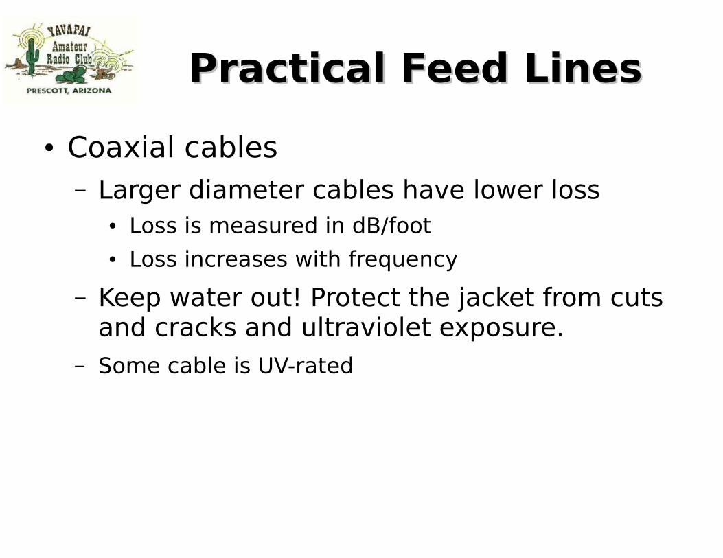
Practical Feed LinesPractical Feed Lines
● Coaxial cables– Larger diameter cables have lower loss
● Loss is measured in dB/foot● Loss increases with frequency
– Keep water out! Protect the jacket from cuts and cracks and ultraviolet exposure.
– Some cable is UV-rated
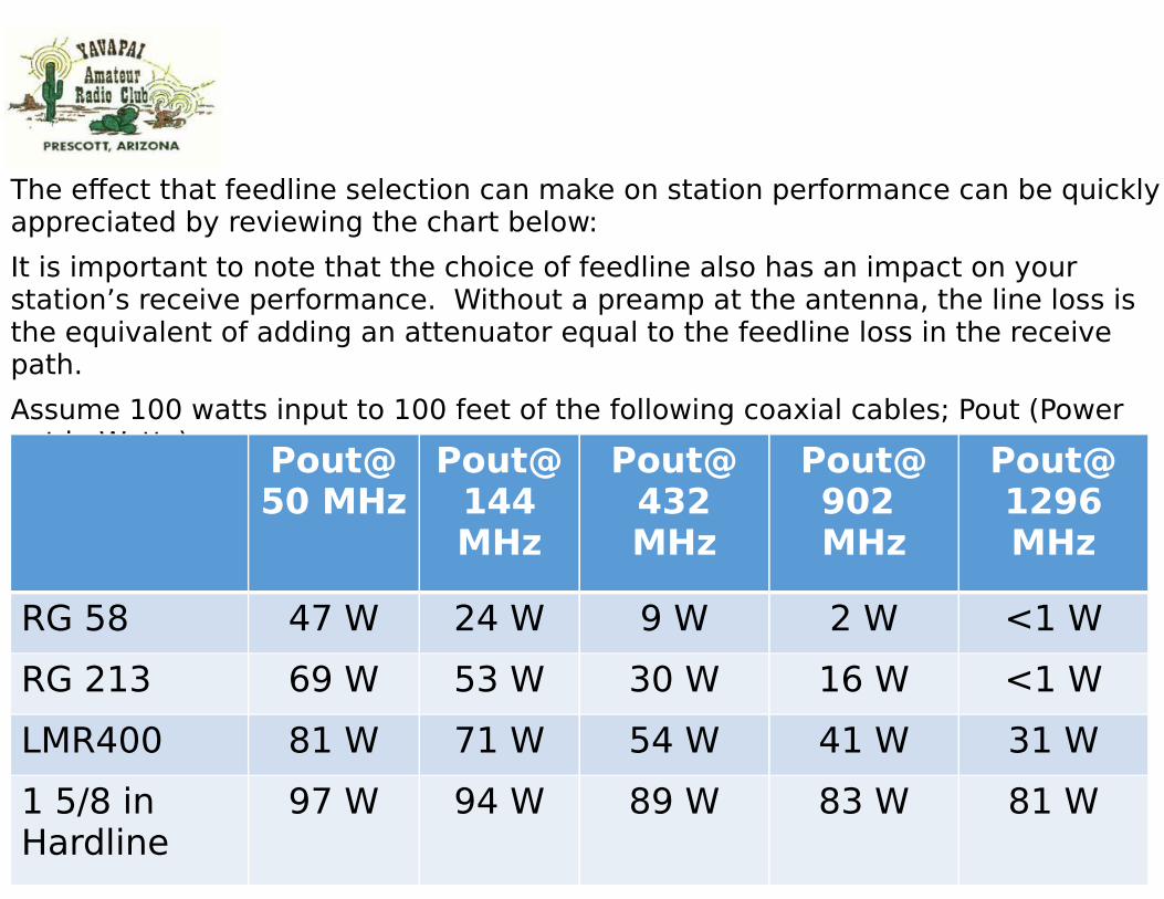
The effect that feedline selection can make on station performance can be quickly appreciated by reviewing the chart below:
It is important to note that the choice of feedline also has an impact on your station’s receive performance. Without a preamp at the antenna, the line loss is the equivalent of adding an attenuator equal to the feedline loss in the receive path.
Assume 100 watts input to 100 feet of the following coaxial cables; Pout (Power out in Watts)
Pout@50 MHz
Pout@144 MHz
Pout@432 MHz
Pout@902 MHz
Pout@1296 MHz
RG 58 47 W 24 W 9 W 2 W <1 W
RG 213 69 W 53 W 30 W 16 W <1 W
LMR400 81 W 71 W 54 W 41 W 31 W
1 5/8 in Hardline
97 W 94 W 89 W 83 W 81 W
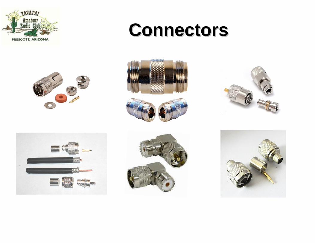
Coaxial ConnectorsCoaxial Connectors
● UHF– SO-239/PL-259
● BNC
● N
● SMA
● F (cable TV)
Connectors Connectors
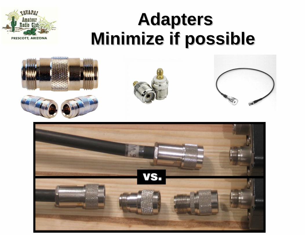
AdaptersAdaptersMinimize if possible Minimize if possible
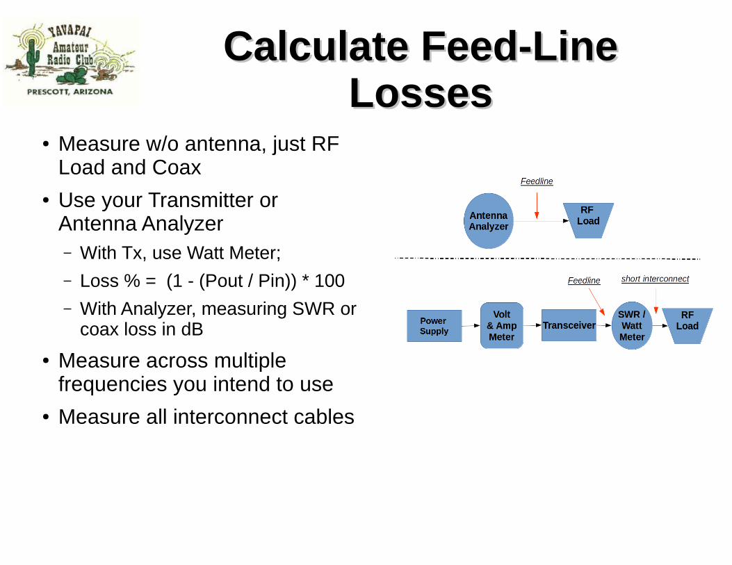
● Use your Transmitter or Antenna Analyzer– With Tx, use Watt Meter; – Loss % = (1 - (Pout / Pin)) * 100– With Analyzer, measuring SWR or
coax loss in dB
● Measure across multiple frequencies you intend to use
● Measure all interconnect cables
Antenna SWR Antenna SWR MeasurementMeasurement
● Ideally want to measure at connector of antenna where feed line goes into
● If you measure with feed line, make sure its integer multiple half wavelength at frequency being measured.– Velocity factor in Coax must
be considered when calculating length of half wavelength.
● Minimize where you can● Loss means less RF
radiates at Antenna● Also can generate Heat
which is wasted energy● High SWR, Loss, can
damage your finals on some rigs.
● There will always some loss in your system.
● But with good antenna, you can also add some gain...
What’s What’s Acceptable?Acceptable?
Tx Power 50 W
VSWR % Reflected
Wasted Watts
At Antenna dB Loss
1 : 1 0.000 0.000 50.000 0.000
1.1 : 1 0.228 0.114 49.886 -0.010
1.2 : 1 0.816 0.408 49.592 -0.036
1.3 : 1 1.710 0.855 49.145 -0.075
1.4 : 1 2.780 1.390 48.610 -0.122
1.5 : 1 4.000 2.000 48.000 -0.177
1.6 : 1 5.500 2.750 47.250 -0.246
1.7 : 1 6.800 3.400 46.600 -0.306
1.8 : 1 8.200 4.100 45.900 -0.372
1.9 : 1 9.600 4.800 45.200 -0.438
2 : 1 11.000 5.500 44.500 -0.506
3 : 1 24.900 12.450 37.550 -1.244
4 : 1 36.000 18.000 32.000 -1.938
5 : 1 44.400 22.200 27.800 -2.549
6 : 1 50.800 25.400 24.600 -3.080
∞ : 1 100.000 50.000 0.000 Err:502
Identify Areas of Possible Identify Areas of Possible Loss (1 or 2 db)Loss (1 or 2 db)
● Old Coaxial cable● Coaxial lengths longer than required● Poor coaxial connections (solder or crimping)● Coaxial switches can lead to loss.
➢Use only good switches
Minor issues can add up to station db loss. Just take
a step back and look at your station
What a difference a decibel What a difference a decibel can make!can make!
Many Hams will say “Oh well, it’s only a decibel (db) or 2 - or 3. That is not very significant – so who cares!” Well, true it is a very small number, but it amounts to one half (1/2) of the power to your station. Every db is important!
You spend a lot of money to create power to your Station, so you don’t want to lose it to leaks and loss.
New Ham: What’s the difference between a 3-element Yagi and a dipole antenna?Elmer: About 6 dB.
In the Technician License Course you learn two rules of thumb about decibels that get you through the exam and provide a rudimentary understanding of their use:
1)A doubling or halving of power equals a change of approximately 3 dB.
2)A 10X change of power equals a change of 10 dB.
● 3 dB equates to about a 2:1 power ratio
● 10 dB (aka 1 bel, or 1×10) equates to a 10:1 power ratio
● 20 dB (aka 2 bel, or 1x10x10) equates to a 100:1 power ratio
● 30 dB (aka 3 bel, or 1x10x10x10) equates to a 1000:1 power ratio
● … and so on
How to calculate Decibels How to calculate Decibels (dB)(dB)
● A ratio expressed as an power of 10 to make large numbers easier to work with.➢ dB = 10 log (power ratio)➢ dB = 20 log (voltage ratio)
● Positive values in dB indicate ratios > 1 and negative values of dB are for ratios < 1.
● Antenna gain is discussed in terms of dB.
2014 Technician License Course
Loss in db is directly proportional to coaxial length. Be sure to cut the coax to the proper length. Don’t leave excess coax just to save the coax for a later project. It will cost you in signal loss.
Standing Wave Ratio (SWR) and coax line loss, i.e. mismatch load
Since reflected power makes two (2) complete trips through the line (coax) each with attenuation it receives twice as much loss as that portion of the power that makes only 1 trip down the line.
Closing ThoughtsClosing Thoughts
● If there is interest, we can setup demonstration perhaps in breakout session in future meeting:– Connector installations
– Verifying your coax cables
● Many of topics touched on tonight can be greatly expanded upon; let club know what you want to see in future talks
● Elmer group does great job at getting your station up and running; as a New Ham you should gain knowledge to maintain / debug for peak performance.