INTERNATIONAL JOURNAL OF SCIENTIFIC & ENGINEERING RESEARCH, VOLUME 9, ISSUE 5, MAY 2018 ISSN 2229-5518
1. Introduction
Cables structures have been used as wide span roof structures due to their various advantages such as high strength, light weight, design flexibility, cost-effective construction and innovative forms. They have application in a variety of wide span structures like exhibition halls, stadiums, sports halls, swimming pools, warehouses, factories and hangers. Cables are flexible tension members that consist of one or more groups of steel wires, strands or ropes. The tensile strength of the wires of the cable exceeds 1570 MPa and the 0.2 % proof stress is over 1180 MPa. Cable-supported structures can be sorted into two categories: cable suspended structures, where draped cables are the main supporting elements of the structure and their curvature is a major factor in the load-carrying capacity of the system; and cable-stayed structures in which cables are tension members fixed inclined to masts or pylons acting as compression members and where cables are straight with small amount of sag due to cables own weight (Buchholdt 1985).
Cables systems are widely applied in bridges, but cable supported system is a relatively new form of roof construction.
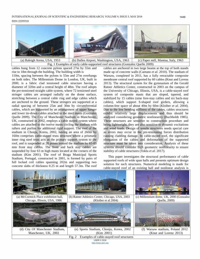
The first cable roofs were four pavilions with hanging roofs constructed in 1896 at an exhibition in Nizjny-Novgorod, Russia, and then some minor cable roofs were built during the 1930’s (Otto and Schleyer 1969). Development of cable roof structures was made between 1950´s and early 1960´s in the United States and Germany. The first major structure with a cable roof was the Arena in Rayleigh, North Carolina, USA, built in 1952. The doubly curved saddle-shaped roof shown in Fig.1 (a) is an anticlastic cable mesh of dimensions 92m by 97m consisting of 47 prestressed cables, suspended between two parabolic concrete arches intercrossing each other. Simply suspended cable systems were also used such as Dulles International Airport near Washington, USA, built in 1963 with a rectangular floor plan 183m by 46m. Steel cables suspended from outward leaning reinforced concrete piers support a precast concrete roof, as shown in Fig. 1 (b). The roof of Burgo paper mill, Fig. 1 (c), designed by Luigi Nervi and built in 1963 at Mantua, Lombardy, Italy, is supported by cables suspended from pylons 45m high with span 163m. Other early examples are the German Pavilion in Montreal Expo, 1967 and the Olympic Park Roof designed for the 1972 Olympics in Munich, Germany (Buchholdt 1985, Irvine 1999).
Several structures were designed with the pre-tensioned straight cable system, some examples are shown in Fig. 2. The pretension cable structures might be either self-balancing where the cables forces are internally balanced in the supporting structure like the masts or ring beam, or non- self- balancing where ground anchors resist the cable forces. McCormick Place exhibition hall in Chicago, Illinois, USA constructed in 1986 over active railroad tracks, has roof consisting of steel trusses supported by steel
Optimum design of wide span cable-stayed roof structures
Gehan A. Hamdy 1a, Emad A. El-Dardiry1∗, Mohamed N. Fayed 2b and Mohamed R. Konswoah1c
1Civil Engineering Department, Faculty of Engineering at Shoubra, Benha University, 108 Shoubra St. 11241, Cairo, Egypt 2Structural Engineering Department, Faculty of Engineering, Ain-Shams University, 1 El-Sarayat St., Abbaseya, Cairo, Egypt
Abstract. This paper investigates the structural response of wide span structures where the primary structural system is cable-stayed roof, and aims at optimizing the design of such structures. Finite element analysis is carried out using commercial software taking into consideration the nonlinear formulation of cables. In order to check the accuracy and capability of the present approach, several examples are presented for nonlinear analysis of cable structures, and the response is found to agree with published results. Additionally, finite element discretization and nonlinear analysis are carried out for an existing cable-stayed roof structure under all possible loading conditions. A numerical study is conducted where four different systems are suggested for the same structure: plane truss, space truss, cable-stayed plane truss and cable-stayed space truss systems. For each system, structural analysis is made under all design load combinations and optimization of design in order to reach the least possible weight and cost. The numerical results indicate the capability of the proposed approach in predicting the forces and deformations of cable structures and optimizing the design of structural element. It was concluded that the space truss and the cable-stayed space truss providing efficient performance as well as economy. Keywords: cable-stayed; roof structure; steel truss; optimum design; finite elements; nonlinear analysis; elastic catenary.
INTERNATIONAL JOURNAL OF SCIENTIFIC & ENGINEERING RESEARCH, VOLUME 9, ISSUE 5, MAY 2018 ISSN 22295518
cables hung from 12 concrete pylons spaced 27m by 55m and rise to 18m through the building. The building width is 110m, spacing between the pylons is 55m and 27m overhangs on both sides. The Millennium Dome in London, UK, built in 2000, is a fabric clad tensioned cable structure having a diameter of 320m and a central height of 48m. The roof adopts the pre-tensioned straight cable system, where 72 tensioned steel stringer cables are arranged radially on the dome surface, stretching between a central cable ring and edge cables which are anchored to the ground. These stringers are supported at a radial spacing of between 25m and 30m by circumferential cables, which are supported by an arrangement of upper hanger and lower tie-down cables attached to the steel masts (Gonzalez Quelle 2009). The City of Manchester Stadium in Manchester, UK, constructed in 2002, employs a cable stayed system where cables are attached to the twelve masts circling the stadium with rafters and purlins for additional rigid support. The roof of the stadium in Chonju, Korea, 2002, having an area of 260m by 160m comprises cable-stayed truss structure where a prismatic inner ring steel truss acts as the primary support system to the roof, and is suspended at 28 points around the stadium by 65-85 mm front stay cables. The front and back stay cables are suspended by four 63 m high masts located at the corners of the stadium (Kim 2001). The roof of Braga Municipal Sports Stadium, Portugal, constructed in 2001, is formed by pairs of full locked coil cables spanning 202m and supporting two concrete slabs of thickness 0.25 m and length 57.3m. The roof
cables are anchored in two large beams at the top of both stands made up of concrete walls (Caetano et al. 2010). The stadium of Warsaw, completed in 2011, has a fully retractable composite membrane central roof supported by 60 cables (Knut and Lorenz 2013). The structural system for the gymnasium of the Gerald Ratner Athletics Center, constructed in 2003 on the campus of the University of Chicago, Illinois, USA, is a cable-stayed roof system of composite masts that are sloped, tapered, and stabilized by 15 cables (nine fore-stay cables and six back-stay cables), which support S-shaped roof girders, allowing a column-free space of about 40m by 60m (Kloiber et al. 2004). Due to the low bending stiffness of the cables, cables structures exhibit relatively large displacements and thus should be analyzed considering geometric nonlinearity (Buchholdt 1985). These structures are sensitive to construction procedure and being lightweight, they are also sensitive to dynamic excitations and wind loads. Design of tensile structures needs special care as errors may occur in the pre-tensioning forces distribution causing cladding damage. In cable-stayed roof, the significant elongation of the cables and deformation of the supported structure must be taken into consideration. Analysis of these systems should consider high geometric nonlinearity to ensure stability of cable structures (Toklu et al. 2017).
This paper investigates the structural performance of cable supported roofs of wide span halls and presents optimum design solution for such structures. Numerical modeling is made for cable-stayed roof of an existing hall and nonlinear analysis is
(a) Raleigh Arena, USA, 1953 (b) Dulles Airport, Washington, USA, 1963 (c) Paper mill, Mantua, Italy, 1963
Fig. 1 Examples of early cable-supported roof structures (Gonzalez Quelle 2009)
(a) McCormick Place exhibition hall, Chicago, Illinois, USA, 1986
(b) Ratner Athletics Center, Chicago, USA, 2003 (Kloiber et al 2004)
INTERNATIONAL JOURNAL OF SCIENTIFIC & ENGINEERING RESEARCH, VOLUME 9, ISSUE 5, MAY 2018 ISSN 2229-5518
carried out under all possible loading conditions to study the structural behavior and evaluate its safety margin. The structural nonlinear analysis is performed by finite element method using the commercial software CSI SAP2000.V 18.2 (2017). Additionally, four different roofs including two cable-stayed systems, were suggested for the same structure, analyzed and compared. Optimization is carried out in order to reach the least possible weight.
2. Analytical and finite element formulations for cables
For modeling of cable structures, two methodologies have been used. The first approach is based on interpolation polynomial functions to describe the shape and displacement; as in finite element analysis. The simplest element most commonly used in the analysis of cable structures is the two-node straight bar element having only axial stiffness, and is regarded to give acceptable response for low-sag, highly stretched cables (Ozdimir 1979). Other models are the multi-node isoperimetric element which uses higher order polynomials, and curved element model with degrees of free rotation added to the nodes (Huu and Seung 2011).
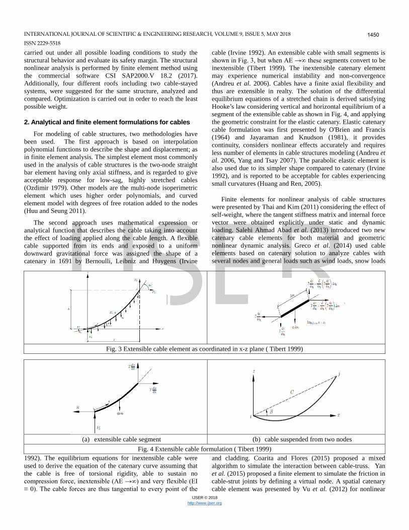
The second approach uses mathematical expression or analytical function that describes the cable taking into account the effect of loading applied along the cable length. A flexible cable supported from its ends and exposed to a uniform downward gravitational force was assigned the shape of a catenary in 1691 by Bernoulli, Leibniz and Huygens (Irvine
1992). The equilibrium equations for inextensible cable were used to derive the equation of the catenary curve assuming that the cable is free of torsional rigidity, able to sustain no compression force, inextensible (AE →∞) and very flexible (EI ≡ 0). The cable forces are thus tangential to every point of the
cable (Irvine 1992). An extensible cable with small segments is shown in Fig. 3, but when AE →∞ these segments convert to be inextensible (Tibert 1999). The inextensible catenary element may experience numerical instability and non-convergence (Andreu et al. 2006). Cables have a finite axial flexibility and thus are extensible in realty. The solution of the differential equilibrium equations of a stretched chain is derived satisfying Hooke’s law considering vertical and horizontal equilibrium of a segment of the extensible cable as shown in Fig. 4, and applying the geometric constraint for the elastic catenary. Elastic catenary cable formulation was first presented by O'Brien and Francis (1964) and Jayaraman and Knudson (1981), it provides continuity, considers nonlinear effects accurately and requires less number of elements in cable structures modeling (Andreu et al. 2006, Yang and Tsay 2007). The parabolic elastic element is also used due to its simpler shape compared to catenary (Irvine 1992), and is reported to be acceptable for cables experiencing small curvatures (Huang and Ren, 2005).
Finite elements for nonlinear analysis of cable structures were presented by Thai and Kim (2011) considering the effect of self-weight, where the tangent stiffness matrix and internal force vector were obtained explicitly under static and dynamic loading. Salehi Ahmad Abad et al. (2013) introduced two new catenary cable elements for both material and geometric nonlinear dynamic analysis. Greco et al. (2014) used cable elements based on catenary solution to analyze cables with several nodes and general loads such as wind loads, snow loads
and cladding. Coarita and Flores (2015) proposed a mixed algorithm to simulate the interaction between cable-truss. Yan et al. (2015) proposed a finite element to simulate the friction in cable-strut joints by defining a virtual node. A spatial catenary cable element was presented by Vu et al. (2012) for nonlinear
(a) extensible cable segment (b) cable suspended from two nodes Fig. 4 Extensible cable formulation ( Tibert 1999)
Fig. 3 Extensible cable element as coordinated in x-z plane ( Tibert 1999)
INTERNATIONAL JOURNAL OF SCIENTIFIC & ENGINEERING RESEARCH, VOLUME 9, ISSUE 5, MAY 2018 ISSN 22295518
analysis of cable-supported structures, considering the effect of self-weight and pretension. The equilibrium equation was solved by an incremental-iterative solution based on the Newton-Raphson method, and an algorithm for form-finding of cable-supported structures is proposed. Cao et al. (2017) extended the analytical form-finding method based on the elastic catenary theory and presented an explicit analytical iteration method for form-finding analysis of suspension bridges; the unstrained lengths are derived from nonlinear governing equations.
3. Adopted nonlinear analysis and optimization procedure
In this work, static nonlinear analysis is performed by finite element method using the commercial software CSI SAP2000.v.18 (2017). The element 'Cable' implemented in the software is used to model the cables. The Cable element uses elastic catenary formulation to represent the behaviour of a slender cable under its own self-weight, temperature, and strain loading. Tension-stiffening and large-deflections nonlinearity are inherently included in the formulation, in addition to slack and taut behaviours. Large displacements analysis considers the equilibrium equations in the deformed configuration of the structure. The program tracks the position of the element using an updated Lagrangian formulation. Different combinations of loads are applied; the nonlinear equations are solved iteratively by Newton-Raphson method.
Optimization process is applied in this study for getting the minimum possible weight of the structure. For optimum design of trusses, Dizangian and Ghasemi (2016) introduced amplification factor-based approach using Response Surface Method instead of than reliability analysis [26]. Artar (2016) used harmony search and genetic algorithms for minimum weight designs by selecting suitable profile sections from a specified list taken from AISC, and developed a computer program interacting with SAP2000 to obtain solution of design problems for several truss structures [27]. In the present work, optimum design is performed via SAP2000 software. Optimization is performed through assign frame section as an auto selective section through many different sections to choose the optimum section that could resist all applied forces with a minimum weight as possible. The stress constraints according to AISC and displacement constraints are considered for optimum designs.
4. Verification and comparative studies
In order to check the accuracy and capability of the present models, examples for evaluating proposed models are studied, and the obtained results are compared to results in published research work.
4.1 Verification example 1: Single suspended cable
This verification example was previously analysed by several researchers in published work. An isolated cable is suspended between two supports at the same level with 304.8 m span and is subjected to a concentrated load of 35.586 kN. The initial shape
of cable is shown in Fig. 5, where the sag of this cable is 30.48 m at the mid span (Thai and Kim 2011, Coarita and Flores 2015). The problem data and cable properties are given in Table 1. Nonlinear static analysis is carried out using the software CSI SAP2000, the problem is modeled by two elastic catenary cable elements. The displacement of point 2 obtained numerically in this work is compared to the value given by other researchers in Table 2. The obtained numerical results for the cable deformed shape due to all loads and the axial force along the cable are shown in Fig. 6. Good agreement can be observed between the obtained and published results
Fig. 5 Verification example 1: Geometry of cable ( Thai and
Kim 2011)
Table 1 Verification example 1: Cable initial properties (Thai and Kim 2011) Item Data Cross-sectional area 548.4 mm2 Elastic modulus 131000 N/mm2 Cable self-weight 46.12 N/m Sag under self-weight at load point 29.276 m Unstressed cable length of sections 1–2 125.88 m Unstressed cable length of sections 2–3 186.85 m
Table 2 Verification example 1: Obtained displacements compared with published research
Researcher Element type Displacement Horiz. Vert.
O’Brien and Francis Elastic catenary -0.860 -5.627 Jayaraman and Knudson Elastic straight -0.845 -5.471 Jayaraman and Knudson Elastic catenary -0.859 -5.626 Tibert Elastic catenary -0.859 -5.626 Andreu et al. Elastic catenary -0.860 -5.626 Yang and Tsay Elastic catenary -0.859 -5.625 Huu and Seung Elastic catenary -0.859 -5.626 Thai and Kim Elastic catenary -0.859 -5.626 Vu et al. Elastic catenary -0.859 -5.626 Salehi Ahmad Abad et al. Elastic catenary -0.859 -5.626 Salehi Ahmad Abad et al. Discrete elastic cat. -0.855 -5.592 Coarita and Flores Elastic catenary -0.860 -5.627 Present work Elastic catenary -0.842 -5.684
INTERNATIONAL JOURNAL OF SCIENTIFIC & ENGINEERING RESEARCH, VOLUME 9, ISSUE 5, MAY 2018 ISSN 2229-5518
4.2 Verification example 2: Single suspended cable The studied example is a hyperbolic paraboloid cable net
roof studied by Lewis (1984) and by Thai and Kim (2011). The spatial cable net consists of 4×4 quadrilaterals formed by 38 pre-tensioned cable segments spaced at 4m in x-direction and y-directions making grid with total dimension 24m and 16m. in plan, as shown in Fig. 7 (a). Cables in the x-direction with cross sectional area 350mm2 have pre-tension force 90 kN, while cables in y-direction with cross section area 120mm2 have 30 kN pre-tension force to maintain the structure initial geometry, and the cables modulus of elasticity is 160 kN/mm2. A vertical force of 6.8 kN force is applied at all internal nodes of the structure.
In this work, the finite element model for the cable net consists of 31 nodes and 38 cable elements, i.e. each cable segment is modeled as one cable element, and nonlinear analysis is carried out. The numerical results for cable net deformations and axial forces in cables are shown in Fig. 7. Table 3 shows the displacements at several nodes numerically evaluated in the present study compared to those obtained by Lewis (1984), Thai and Kim (2011) and Salehi Ahmad Abad et al. (2013). The displacements are very close to values obtained by the other researchers.
4.3 Case study: Existing cable-stayed roof structure
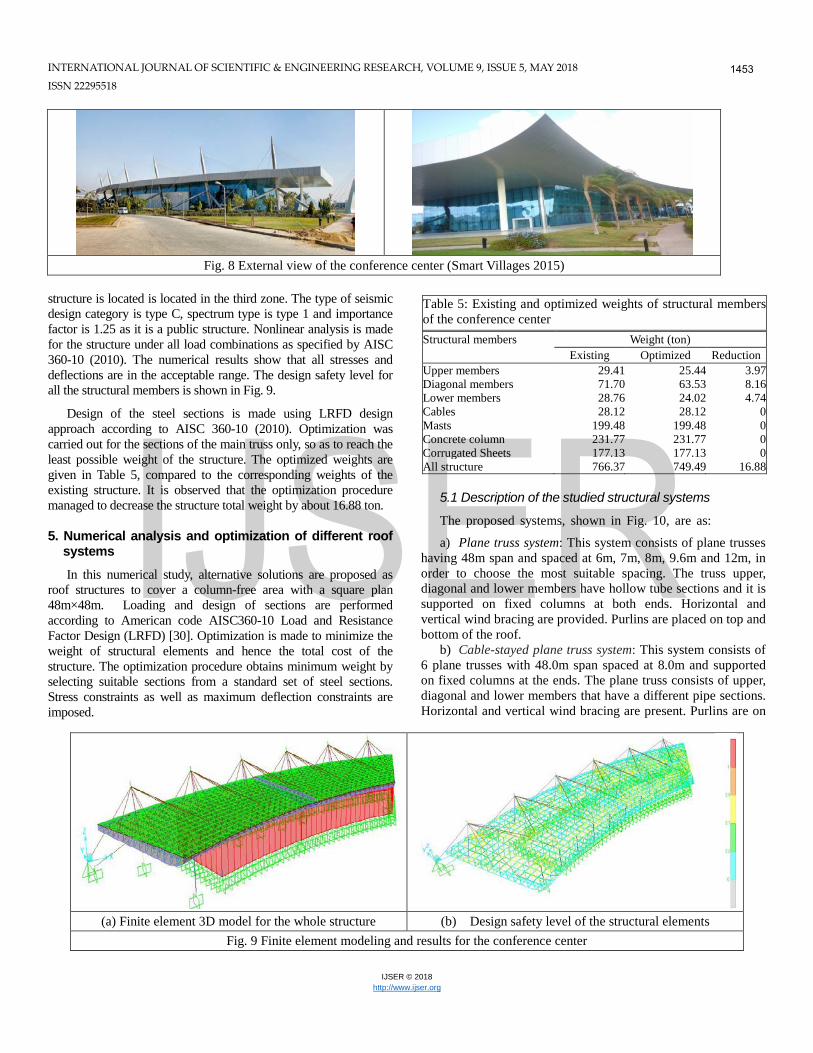
The studied application is the cable-stayed roof of the Conference Center located in Smart Village, Giza, Egypt, constructed in 2002 (Smart Villages 2015). The main structural system of conference center is a space truss roof supported by cables connected to six masts, as shown in Fig. 8. The space truss is supported along the perimeter on Steel columns connected to the space truss through steel plates that are welded and bolted.
A 3-dimensional model for the entire structure by finite elements is made in order to study the overall and detailed structural behavior under the studied loads. The properties assigned for the different materials of the structure and included in the computer program are as follows: Mild steel is used for all steel elements having yield stress fy 420 N/mm2; reinforced concrete elements have concrete cube compressive strength fcu 40 N/mm2 and yield stress for cables is 350 N/mm2.
The finite element model consists of 1748 nodes, 46 cable elements, 6084 frame elements (used to model truss elements, purlins, concrete columns, steel columns and steel masts) and 1882 shells elements (used to model the structure external cladding). Fixed supports are assigned to the masts and columns and hinged supports are assigned to the cables. The three-dimensional finite element model for the conference center model is shown in Fig. 9 with its different structural elements such as cables, frames and shell elements.
The loads acting on the structure such as the roof loads, wind loads and seismic loads adopted in this study are given in Table 4. Dead loads are the weight of the roof cladding, purlins and truss elements, in addition to the weight of other utilities such as lighting fixtures, AC ducts and others. The live load on the inaccessible roof is assigned a value of 60 kg/m2. Wind load is considered as equivalent static lateral load. Seismic loads are calculated as horizontal and vertical loads, considering ground acceleration ag/g equal to 0.15, as the
Fig. 6 Verification example 1: Numerical results for
deformed shape and axial force in cable
Table 3 Verification example 2 – Resulting displacements compared with published research
Researcher Lewis (1984) Thai and Kim (2011) Salehi Ahmad Abad et al. (2013) Present study
INTERNATIONAL JOURNAL OF SCIENTIFIC & ENGINEERING RESEARCH, VOLUME 9, ISSUE 5, MAY 2018 ISSN 22295518
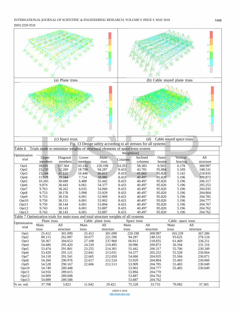
structure is located is located in the third zone. The type of seismic design category is type C, spectrum type is type 1 and importance factor is 1.25 as it is a public structure. Nonlinear analysis is made for the structure under all load combinations as specified by AISC 360-10 (2010). The numerical results show that all stresses and deflections are in the acceptable range. The design safety level for all the structural members is shown in Fig. 9.
Design of the steel sections is made using LRFD design approach according to AISC 360-10 (2010). Optimization was carried out for the sections of the main truss only, so as to reach the least possible weight of the structure. The optimized weights are given in Table 5, compared to the corresponding weights of the existing structure. It is observed that the optimization procedure managed to decrease the structure total weight by about 16.88 ton.
5. Numerical analysis and optimization of different roof
systems
In this numerical study, alternative solutions are proposed as roof structures to cover a column-free area with a square plan 48m×48m. Loading and design of sections are performed according to American code AISC360-10 Load and Resistance Factor Design (LRFD) [30]. Optimization is made to minimize the weight of structural elements and hence the total cost of the structure. The optimization procedure obtains minimum weight by selecting suitable sections from a standard set of steel sections. Stress constraints as well as maximum deflection constraints are imposed.
5.1 Description of the studied structural systems
The proposed systems, shown in Fig. 10, are as:
a) Plane truss system: This system consists of plane trusses having 48m span and spaced at 6m, 7m, 8m, 9.6m and 12m, in order to choose the most suitable spacing. The truss upper, diagonal and lower members have hollow tube sections and it is supported on fixed columns at both ends. Horizontal and vertical wind bracing are provided. Purlins are placed on top and bottom of the roof.
b) Cable-stayed plane truss system: This system consists of 6 plane trusses with 48.0m span spaced at 8.0m and supported on fixed columns at the ends. The plane truss consists of upper, diagonal and lower members that have a different pipe sections. Horizontal and vertical wind bracing are present. Purlins are on
Fig. 8 External view of the conference center (Smart Villages 2015)
(a) Finite element 3D model for the whole structure (b) Design safety level of the structural elements
Fig. 9 Finite element modeling and results for the conference center
Table 5: Existing and optimized weights of structural members of the conference center
Structural members Weight (ton) Existing Optimized Reduction
Upper members 29.41 25.44 3.97 Diagonal members 71.70 63.53 8.16 Lower members 28.76 24.02 4.74 Cables 28.12 28.12 0 Masts 199.48 199.48 0 Concrete column 231.77 231.77 0 Corrugated Sheets 177.13 177.13 0 All structure 766.37 749.49 16.88
INTERNATIONAL JOURNAL OF SCIENTIFIC & ENGINEERING RESEARCH, VOLUME 9, ISSUE 5, MAY 2018 ISSN 2229-5518
top and bottom of the roof. Cables are used to connect masts to the roof truss at specified joints.
a) Space truss system: This system consists of a space truss with 48m span supported on fixed columns on the perimeter. Horizontal and vertical wind bracing resist wind load. Purlins are on top and bottom of the roof.
b) Cable-stayed space truss system: This system consists of a space truss roof covering a column-free square area of 48m×48m. The space truss is supported on concrete columns on the perimeter of the hall; in addition to cables connected to six masts on each side.
Plans and elevations for all the studied systems are shown in Fig. 10.
5.2 Finite element analysis Finite element modeling is made for the four proposed
structural systems using SAP2000 software. Steel pipes have
been used to model the truss members in the finite element model. For columns and masts, steel pipes were assigned with fixed joints at foundation level. Roof cladding was assigned as a
very light thin shell element as well as the wall cladding taking the distribution for all load types to transfer it into frames. All shell elements were divided at every points and frames. Steel cables were assigned in software program via input its diameter and its pre-tension force, for systems (b) and (d). The finite element mesh for all systems is shown in Fig. 11.
Analysis is performed for each structural system under all possible cases of loadings and load combinations of AISC360-10 code. The assigned loads including dead load, live load, seismic, wind and temperature loads of the proposed roofs are the same as that assigned in the conference center given in Table 4. The wind load on the structure was taken according to AISC360-10 [30]. Linear analysis is conducted for roof structures without cables and nonlinear analysis for roof structures with cables.
(a) Plane truss (b) Cable stayed plane truss
(c) Space truss (d) Cable stayed space truss
Fig. 10 Plan and elevation of the proposed roof systems
INTERNATIONAL JOURNAL OF SCIENTIFIC & ENGINEERING RESEARCH, VOLUME 9, ISSUE 5, MAY 2018 ISSN 22295518
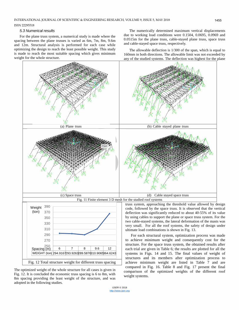
5.3 Numerical results For the plane truss system, a numerical study is made where the
spacing between the plane trusses is varied as 6m, 7m, 8m, 9.6m and 12m. Structural analysis is performed for each case while optimizing the design to reach the least possible weight. This study is made to reach the most suitable spacing which gives minimum weight for the whole structure.
The optimized weight of the whole structure for all cases is given in Fig. 12. It is concluded the economic truss spacing is 6 to 8m, with 8m spacing providing the least weight of the structure, and was adopted in the following studies.
The numerically determined maximum vertical displacements due to working load conditions were 0.1504, 0.0695, 0.0969 and 0.0515m for the plane truss, cable-stayed plane truss, space truss and cable-stayed space truss, respectively.
The allowable deflection is 1/300 of the span, which is equal to 160mm in both directions. The allowable limit was not exceeded by any of the studied systems. The deflection was highest for the plane
truss system, approaching the threshold value allowed by design code, followed by the space truss. It is observed that the vertical deflection was significantly reduced to about 40-55% of its value by using cables to support the plane or space truss system. For the two cable-stayed systems, the lateral deformation of the masts was very small. For all the roof systems, the safety of design under ultimate load combinations is shown in Fig. 13.
For each structural system, optimization process was made to achieve minimum weight and consequently cost for the structure. For the space truss system, the obtained results after each trial are given in Table 6; the results are plotted for all the systems in Figs. 14 and 15. The final values of weight of structures and its members after optimization process to achieve minimum weight are listed in Table 7 and are compared in Fig. 16. Table 8 and Fig. 17 present the final
comparison of the optimized weights of the different roof weight systems.
(a) Plane truss (b) Cable stayed plane truss
(c) Space truss (d) Cable stayed space truss Fig. 11 Finite element 3 D mesh for the studied roof systems
Fig. 12 Total structure weight for different truss spacing
INTERNATIONAL JOURNAL OF SCIENTIFIC & ENGINEERING RESEARCH, VOLUME 9, ISSUE 5, MAY 2018 ISSN 22295518
(a) Plane truss (b) Cable stayed plane truss Fig. 14 Weight of structural elements of plane truss and cable-stayed plane truss systems through the optimizing trials
(c) Space truss (d) Cable stayed space truss Fig. 15 Weight of structural elements of space truss and cable-stayed space truss systems through the optimizing trials
(a) Total weight of the structure (b) Weight of main truss Fig. 16 Structure and main truss weight of all systems throughout the optimization trials
0
50
100
150
200
250
300
350
1 2 3 4 5 6 7 8 9 10 11 12 13 14
Weight (ton)
Opt. trial
Plane truss system All
structure Main truss
Upper members Diagonal members
Lower members Inclined
columns Upper purlins Lower purlins Outer
beams 0
50
100
150
200
250
300
350
1 2 3 4 5 6 7 8 9 10
Weight (ton)
Opt. trial
Cable-stayed plane truss system All
structure Main truss
Outer beams Masts
Upper members Diagonal members
Lower members Vertical bracing Horizontal
bracing
0
50
100
150
200
250
300
350
1 2 3 4 5 6 7 8 9 10 11 12 13
Weight (ton)
Opt. trial
Space truss system All
structure Main truss
Inclined columns Outer
beams Upper
members Diagonal members
Lower members Vertical bracing 0
50
100
150
200
250
300
350
400
1 2 3 4 5 6 7 8 9 10
Weight (ton)
Opt. trial
Cable-stayed space truss system All
structure Main truss
Upper members Diagonal members
Lower members Masts
Columns
0
50
100
150
200
250
300
350
400
1 2 3 4 5 6 7 8 9 10 11 12 13
Weight (ton)
Opt. trial
Total weight of structure
Plane truss Cable-stayed plane truss Space truss
Cable-stayed space truss
0
50
100
150
200
250
300
1 2 3 4 5 6 7 8 9 10 11 12 13
Weight (ton)
Opt. trial
Weight of main truss
Plane truss Cable-stayed plane truss Space truss Cable-stayed space truss
INTERNATIONAL JOURNAL OF SCIENTIFIC & ENGINEERING RESEARCH, VOLUME 9, ISSUE 5, MAY 2018 ISSN 2229-5518
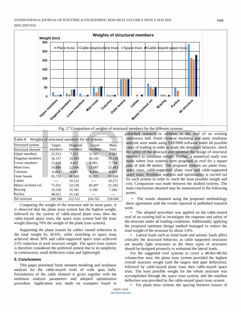
Comparing the weight of the structure and its main parts, it is observed that the plane truss system has the highest weight, followed by the system of cable-stayed plane truss then the cable-stayed space truss; the space truss system had the least weight (having 70% the weight of the plane truss system).
Supporting the plane trusses by cables caused reduction in the total weight by 26.6%, while switching to space truss achieved about 30% and cable-supported space truss achieved 21% reduction in total structure weight. The space truss system is therefore considered the preferred system due to its simplicity in construction, small deflection value and lightweight
5. Conclusions This paper presented finite element modeling and nonlinear
analysis for the cable-stayed roofs of wide span halls. Formulation of the cable element is given together with the nonlinear analysis parameters and adopted optimization procedure. Application was made on examples found in
published research in addition to the roof of an existing conference hall. Finite element modeling and static nonlinear analysis were made using SAP2000 software under all possible cases of loading in order to study the structural behavior, check the safety of the structure and optimize the design of structural members to minimize weight. Further, a numerical study was made where four systems were proposed as roof for a square plan of side 48 meters. The proposed systems are plane truss, space truss, cable-supported plane truss and cable-supported space truss. Nonlinear analysis and optimization is carried out for each system in order to reach the least possible weight and cost. Comparison was made between the studied systems. The main conclusions obtained may be summarized in the following points.
• The results obtained using the proposed methodology show agreement with the results reported in published research
work. • The adopted procedure was applied on the cable-stayed
roof of an existing hall to investigate the response and safety of the structure under all loading conditions. Additionally, applying the proposed optimum design method managed to reduce the total weight of the structure by about 3.0%.
• Lateral loads such as wind loads and seismic loads affect critically the structural behavior, as cable supported structures are usually light structures so the these types of structures should be designed primarily to withstand the lateral loads.
For the suggested roof systems to cover a 48.0m×48.0m column-free area, the plane truss system provided the highest overall structure weight (and the largest mid span deflection), followed by cable-stayed plane truss then cable-stayed space truss. The least possible weight for the whole structure was accomplished through the space truss system, and the smallest deflection was provided by the cable-stayed space truss system.
• For plane truss system, the spacing between trusses of
Fig. 17 Comparison of weights of structural members for the different systems
Table 8 Weights of structural members for all systems Structural system Structural element
INTERNATIONAL JOURNAL OF SCIENTIFIC & ENGINEERING RESEARCH, VOLUME 9, ISSUE 5, MAY 2018 ISSN 22295518
8.0m was found to yield the minimum total structure weight and thereby cost.
• The space truss system has the additional advantages of simple design, safety, economical cost, easy construction and easy conservation, over the cable-stayed plane or space truss systems.
• The conclusions derived from this study may not be identical for halls with larger spans, where further investigation will be required to reach such conclusions.
• In this study, no specific modeling was adopted to represent the connections, and thus further studies should take into account the effect of connections on the structural response. References
[1] Buchholdt, H.A. (1985), An Introduction to Cable Roof Structures,
Cambridge University Press, Cambridge, USA. [2] Otto, F. and Schleyer, K. (1969), Tensile Structures, Volume 2:
Cable Structures, MIT Press, Cambridge, USA. [3] Irvine, H.M. (1992), Cable Structures, Dover Publications, New
York, USA. [4] Gonzalez Quelle, I. (2009), "Cable roofs: evolution, classification
and future trends", Proceedings of the International Association for Shell and Spatial Structures (IASS) Symposium, Valencia, Spain, October.
[5] Kim, J.S. (2001), "Cable-stayed trusses of the Sports Stadium, Chonju", Structural Engineering International, 11(1), 33-35.
[6] Caetano, E., Cunha, A. and Magalhães, F. (2010), "Numerical and experimental studies of the Braga Sports Stadium suspended roof", Structure and Infrastructure Engineering, 6 (6), 715-724.
[7] Knut, G. and Lorenz, H. (2013), "National Stadium Warsaw, Poland", Structural Engineering International, 23 (3), 311-316.
[8] Kloiber, L.A., Eckmann, D.E., Meyer, T.R. and Hautzinger, S.J. (2004), "Design considerations in cable-stayed roof structures", Proceedings of North American Steel Construction Conference, USA, March.
[9] Toklu, Y. C., Bekdaş, G. and Temur, R. (2017), "Analysis of cable structures through energy minimization", Structural Engineering and Mechanics - An Int'l Journal, 62 (6), 749-758.
[10] SAP2000.V18.2 (2017), "CSI Analysis Reference Manual", Computer and Structures, Berkeley, USA.
[11] Tibert, G. (1999), "Numerical Analyses of Cable Roof Structures", Licentiate Thesis, Department of Structural Engineering, Royal Institute of Technology, UK.
[12] Ozdemir, H. (1979), "A finite element approach for cable problems", Int. J. Solid Struct., 15, 427-437.
[13] Huu, T. and Seung, K. (2011), "Nonlinear static and dynamic of cable structures", Finite Elements in Analysis and Design, 47, 237-246.
[14] Andreu, A., Gil, L. and Roca, P. (2006), “A new deformable catenary element for the analysis of cable net structures,” Computer and Structures, 84, 1882-1890.
[15] O'Brien, W.T. and Francis, A.J. (1964), "Cable movements under two-dimensional loads", J. Struct. Div. ASCE, 90, 89-124.
[16] Jayaraman, H. and Knudson, W. (1981), "A curved element for the analysis of cable structures", Computers and Structures, 14 (3/4), 325-333.
[17] Yang, Y.B. and Tsai, J.Y. (2007), "Geometric nonlinear analysis of cable structures with a two-node cable element by generalized displacement control method," Int. J. Structural. Stability and Dynamics, 7, 571-588.
[18] Huang, M.G., Ren, W.X., A new parabolic cable element in static analysis, in: The Ninth International Conference on Inspection, Appraisal, Repairs and Maintenance of Structures, Fuzhou, China, 2005, 271-282.
[19] Thai, H.T. and Kim, S.E. (2011), "Nonlinear static and dynamic analysis of cable structures", Finite Elements in Analysis and Design, 47, 237-246.
[20] Salehi Ahmad Abad, M., Shooshtari, A., Esmaeili, V. and Riabi, A.N. (2013), "Nonlinear analysis of cable structures under general loadings", Finite Elements in Analysis and Design, 73, 11-19.
[21] Greco, L., Impollonia, N. and Cuomo, M. (2014), "A procedure for the static analysis of cable structures following elastic catenary theory", International Journal of Solids and Structures, 51, 1521-1533.
[22] Coarita E. and Flores, L. (2015), "Nonlinear Analysis of Structures Cable – Truss", IACSIT International Journal of Engineering and Technology, 7 (3), 160-169.
[23] Yan, R., Chen, Z., Wang, X., Liu, H. and Xiao, X. (2015), "A new equivalent friction element for analysis of cable supported structures", Steel and Composite Structures, An Int'l Journal, 18 (4), 947-970.
[24] Vu, T.V., Lee, H.E. and Bui, Q.T. (2012), "Nonlinear analysis of cable-supported structures with a spatial catenary cable element", Structural Engineering and Mechanics, An Int'l Journal, 43 (5), 583-605.
[25] Cao, H., Zhou, Y., Chen, Z. and Abdel Wahab, M. (2017), "Form-finding analysis of suspension bridges using an explicit Iterative approach", Structural Engineering and Mechanics, An Int'l Journal, 62 (1), (2017) 85-95.
[26] Dizangian, B. and Ghasemi, M. R. (2016), "An efficient method for reliable optimum design of trusses", Steel and Composite Structures, An Int'l Journal, 21 (5), 1069-1084.
[27] Artar, M. (2016), "A comparative study on optimum design of multi-element truss structures", Steel and Composite Structures, An Int'l Journal, 22 (3), 1000-1010.
[28] Lewis, W.J., Jones, M.S. and Rushton, K.R. (1984), "Dynamic relaxation analysis of the non-linear static response of pretensioned cable roofs," Computers and Structures, 18, 989–997.


![[TECH]Cable Stayed Bridges](https://static.documents.pub/doc/80x56/544cd985b1af9f3a0b8b4c5b/techcable-stayed-bridges.jpg)

