answers to test yourself questionsoption cc1 introduction to imaging
1 a The focal point of a converging lens is that point on the principal axis where a ray parallel to the principal axis refracts through, after passage through the lens.
b The focal length is the distance of the focal point from the middle of the lens. In the lens equation this is taken to be a negative number.
2 a A real image is an image formed by actual rays of light which have refracted through a lens. b A virtual image is formed not by actual rays but by the intersection of their mathematical extensions.
3 If a screen is placed at the position of a real image the actual rays of light that go through that image will be reflected off the screen and so the image will be seen on the screen. In the case of a virtual image, placing a screen at the position of the image reveals nothing as there are no rays of light to reflect off the screen.
4 No one can explain things better than Feynman and this case is no exception. Search for the YouTube video “Feynman: FUN TO IMAGINE 6: The Mirror” where Feynman explains the apparent left-right case for the mirror. Then try to see what happens with a lens.
5 The distance is the focal length so 6.0 cm.
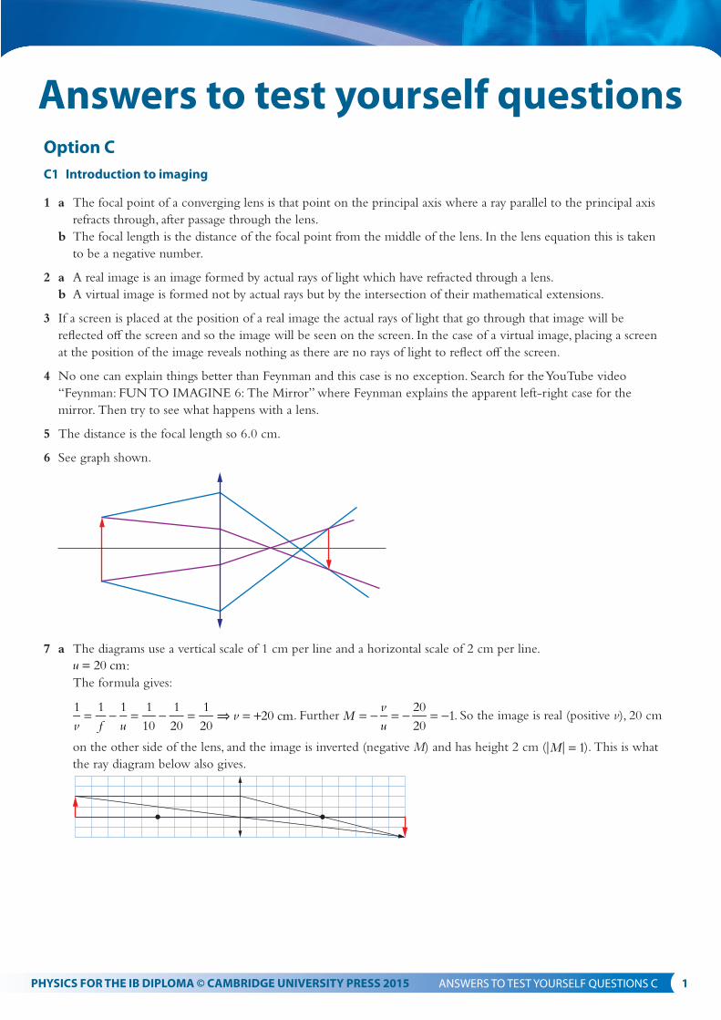
6 See graph shown.
7 a The diagrams use a vertical scale of 1 cm per line and a horizontal scale of 2 cm per line.
u 20 cm= : The formula gives:
v f uv
1 1 1 1
10
1
20
1
2020 cm= − = − = ⇒ = + . Further M
vu
20
201= − = − = − . So the image is real (positive v), 20 cm
on the other side of the lens, and the image is inverted (negative M) and has height 2 cm ( M 1= ). This is what the ray diagram below also gives.
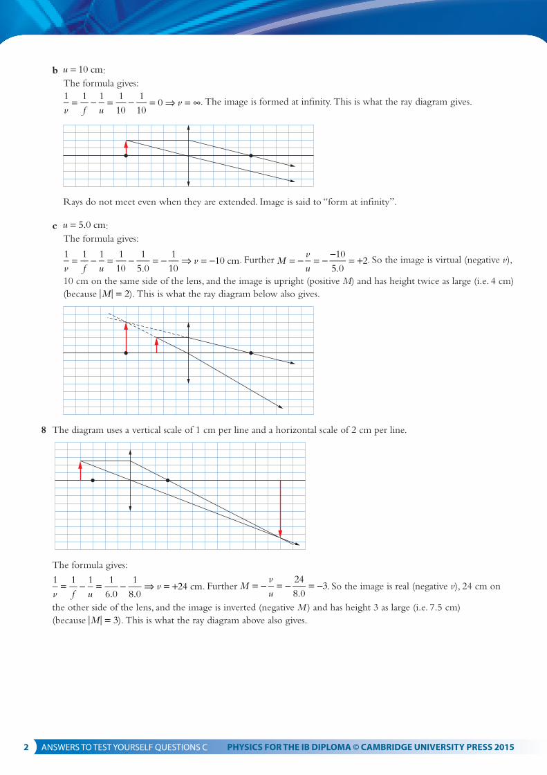
100= − = − = ⇒ = ∞. The image is formed at infinity. This is what the ray diagram gives.
Rays do not meet even when they are extended. Image is said to “form at infinity”.
c u 5.0 cm= : The formula gives:
v f uv
1 1 1 1
10
1
5.0
1
1010 cm= − = − = − ⇒ = − . Further M
vu
10
5.02= − = − − = + . So the image is virtual (negative v),
10 cm on the same side of the lens, and the image is upright (positive M) and has height twice as large (i.e. 4 cm) (because M 2= ). This is what the ray diagram below also gives.
8 The diagram uses a vertical scale of 1 cm per line and a horizontal scale of 2 cm per line.
The formula gives:
v f uv
1 1 1 1
6.0
1
8.024 cm= − = − ⇒ = + . Further M
vu
24
8.03= − = − = − . So the image is real (negative v), 24 cm on
the other side of the lens, and the image is inverted (negative M ) and has height 3 as large (i.e. 7.5 cm) (because M 3= ). This is what the ray diagram above also gives.
The diagram uses a vertical scale of 1 cm per line and a horizontal scale of 2 cm per line.
The formula gives:
v f uv
1 1 1 1
8.0
1
6.0
1
2424 cm= − = − = − ⇒ = − . Further M
vu
24
6.04= − = − − = + . So the image is virtual
(negative v), 24 cm on the same side of the lens, and the image is upright (positive M) and has height 4 as large (i.e. 16 cm) (because M 4= ). This is what the ray diagram below also gives.
10 We know that v 0> (real image) and Mvu
1= − = − (same size). Hence v u= and so
u v f u fu f
1 1 1 2 12 9.0 cm+ = ⇒ = ⇒ = = .
11 See the diagram that follows. The rays from the top of the object have been drawn green and those from the bottom blue for the sake of clarity.
The top of the image will be formed at a distance from the lens given by:
v f uv
1 1 1 1
5.0
1
9.011.25 cm= − = − ⇒ = and the bottom at a distance of
v f uv
1 1 1 1
5.0
1
10.010.0 cm= − = − ⇒ = .
The angle the object makes with the horizontal is tan4
12 a Since we know that f u v1 1 1= + we should plot
u1 versus
v1. We expect a straight line with gradient equal to 1−
and equal vertical and horizontal intercepts equal to f1
.
b The graph shows the data points and the (small) error bars.
0.02
0.01
0.02
0.03
0.04
0.05
0.06
0.04 0.06 0.081 / u
1 / v
The line of best fit is v u1
0.0960.95= − . The intercepts are 0.096 and
0.096
0.95 giving focal lengths
ff
10.096 10.42 cm= ⇒ = and
ff
1 0.096
0.959.896 cm= ⇒ = . So approximately, f 10.2 0.3 cm= ± .
13 From the diagram it should be clear that rays must hit the mirror at right angles if they are to return to the position of the object. This means that the distance of the object from the lens when the object and image coincide is the focal length.
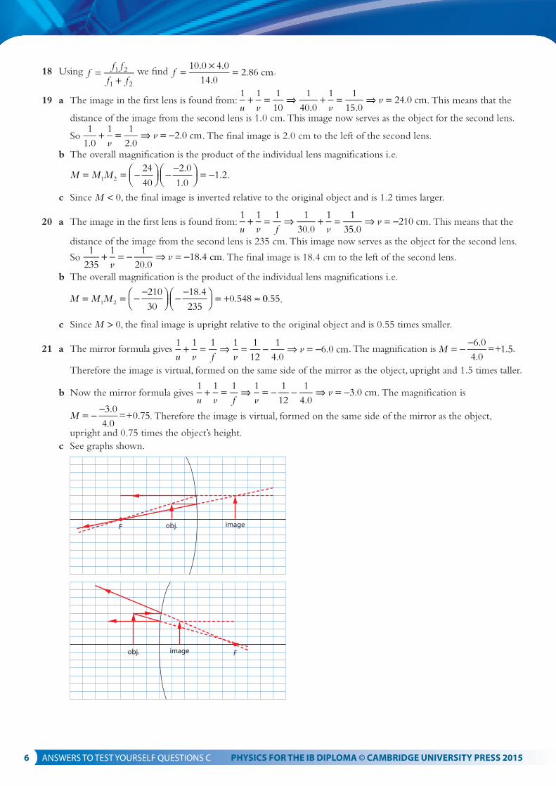
22 We are told that M +2.0= (image is upright so M > 0) hence vu
v u2.0 2.0 24 cm= − ⇒ = − = − . Hence from the
mirror formula gives u v f1 1 1+ = we get
ff
1 1
12
1
2424 cm= − ⇒ = . Since the focal length is positive the mirror is
concave.23 a There are two main lens aberrations. In spherical aberration rays that are far from the principal axis have a
different focal length than rays close to the principal axis. This results in images that are blurred and curved at the edges. In chromatic aberration, rays of different wavelength have slightly different focal lengths resulting in images that are blurred and coloured. Spherical aberration is reduced by only allowing rays close to the principal axis to enter the lens and chromatic aberration is reduced by combining the lens with a second diverging lens.
b i The diagram shows (under the simple conditions of this problem) that a different focal length (depending on the distance of the paraxial rays from the principal axis) creates an image that is curved at the edges.
ii The image drawn with one focal length would be straight.
24 We are told that u f x= + and v f y= + . Then f x f y f
f x f yf x f y
f1 1 1 ( )( )
++
+= ⇒ + +
+ + += . Simplifying,
f fx fy xy f f x y f fx fy
xy f
(2 ) 22 2
2
+ + + = + + = + +
=
25 a The image is virtual so v 25 cm= − . u v u
u1 1 1
10.0
1 1
25
1
10.07.143 7.1 cm+ = ⇒ − = ⇒ = ≈ .
b At the focal point of the lens, 10 cm away.
c The angular magnification in this case is Mf25 25
102.5= = = and M
θθ
= ′. Now
1.6 10
0.250.0064 rad
3
θ ≈ × =−
and so θ ′ ≈ × =2.5 0.0064 0.016 rad.
26 a See graph shown.
image
D
h
F Fu
h′
θ′
b The nearest point to the eye where the eye can focus without straining. c When the image is formed at the near point (25 cm away) we have that v 25 cm= − .
= = = . The diameter of the image of the moon is then
30 0.00921 0.276 0.28 rad× = ≈ .
35 a The angular magnification is Mf
f80
204.0o
e
= = = .
b The angle subtended by the building without a telescope is 65
25000.0260 radθ = = and so the angle subtended
by the image is M 4 0.0260 0.104 radθ θ′ = = × = .
36 a Mf
f67
3.022.3 22o
e
= = = ≈ .
b f f 70 cmo e+ =
37 The objective focal length must be 57 cm. If the final image is formed at infinity, it means that the image in the objective is formed at a distance of 3.0 cm from the eyepiece i.e. 61.5 3.0 58.5 cm− = from the objective lens.
Hence u
u1 1
58.5
1
57.02223 cm 22 m+ = ⇒ = ≈ .
38 a A technique in radio astronomy in which radio waves emitted by distant sources are observed by an array of radio telescopes which combine the individual signals into one.
b b
1.22 1.220.21
25 101.0 10 rad3
5θ λ≈ × = ××
= × − .
c The smallest angular separation that can resolved is 1.0 10 rad5× − . The smallest distance is therefore
2 10 1.0 10 2 10 m22 5 17× × × = ×− .
39 The universe is full of sources that emit at all parts of the electromagnetic spectrum not just optical light.
40 They do not suffer from spherical aberrations.
41 Advantages: free of atmospheric turbulence and light pollution; no atmosphere to absorb specific wavelengths Disadvantages: expensive to put in orbit; expensive to service.
c3 fibre optics
42 ncc
ccn
3 10
1.452.07 10 m s
mm
88 1= ⇒ = = × = × − .
43 a The phenomenon in which a ray approaching the boundary of two media reflects without any refraction taking place.
b Critical angle is that angle of incidence for which the angle of refraction is 90.
c The critical angle is found from n nnn
sin sin90 sinc c1 22
1
θ θ= ⇒ = . Since the sine of an angle cannot exceed 1
we must have n n2 1< for the critical angle to exist. So total internal reflection is a one way phenomenon.
b From the diagram, A n a1 sin sin1× = . But a 90 C θ= − and so asin sin(90 ) cosC C
θ θ= − = . Hence
A n nn n
nn nsin cos1 C 1
12
22
112
22θ= = ×
−= − .
c A n narcsin arcsin 1.50 1.40 32.612
22 2 2 = − = − = .
46 A n narcsin arcsin 1.52 1.44 29.112
22 2 2 = − = − = .
47 We must have n n1.42 1 1.7367 1.7412 2
1− = ⇒ = ≈ .
48 It has to be exceptionally pure.
49 a Dispersion is the phenomenon in which the speed of a wave depends on wavelength. This means that the different wavelength components of a beam of light will take different times to travel the same distance.
b Material dispersion is the dispersion discussed in (a). Waveguide dispersion has to do with rays of light following different paths in an optic fibre and hence taking different times to arrive at their destination.
50 a ncc
ccn
3 10
1.521.9737 10 1.97 10 m s
mm
88 8 1= ⇒ = = × = × ≈ × − .
b The shortest time will be for a ray that travels down the length of the fibre on a straight line of length
8.0 km, i.e. the time of travel will be 8.0 10
1.9737 104.05 10 s
3
85×
×= × − . The longest time of travel will be for
that ray that undergoes as many internal reflections as possible. The length of the path travelled is then
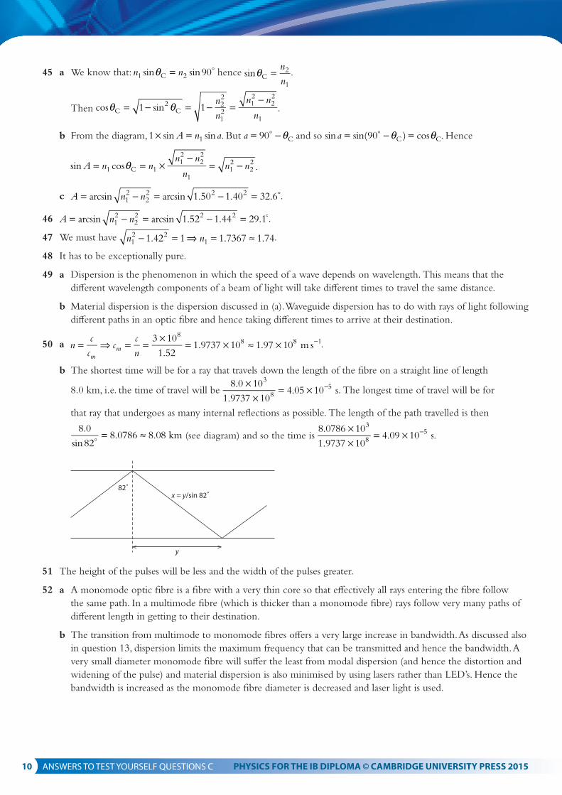
8.0
sin828.0786 8.08 km
= ≈ (see diagram) and so the time is 8.0786 10
1.9737 104.09 10 s
3
85×
×= × − .
82˚x = y/sin 82˚
y
51 The height of the pulses will be less and the width of the pulses greater.
52 a A monomode optic fibre is a fibre with a very thin core so that effectively all rays entering the fibre follow the same path. In a multimode fibre (which is thicker than a monomode fibre) rays follow very many paths of different length in getting to their destination.
b The transition from multimode to monomode fibres offers a very large increase in bandwidth. As discussed also in question 13, dispersion limits the maximum frequency that can be transmitted and hence the bandwidth. A very small diameter monomode fibre will suffer the least from modal dispersion (and hence the distortion and widening of the pulse) and material dispersion is also minimised by using lasers rather than LED’s. Hence the bandwidth is increased as the monomode fibre diameter is decreased and laser light is used.
53 Advantages include: (i) the low attenuation per unit length which means that a signal can travel large distances before amplification (ii) increased security because the signal can be encrypted and the transmission line itself cannot easily be
tampered with (iii) large bandwidth and so a large information carrying capacity (iv) not susceptible to noise (v) they are thin and light and (vi) do not radiate so there is no crosstalk between lines that are close to each other.
54 The main cause of attenuation in an optic fibre is scattering of light off impurities in the glass making up the core of the fibre.
55 Let Pin be the power in to the first amplifier. Then the power out of the first amplifier is P P 10G
in10
1
′ = × . This is
input to the second amplifier so its output is P P PG G G G
out in in= ×
× = ×+
10 10 101 2 1 2
10 10 10 100 10101 2
= ×+
PG G
in showing
that the gain overall is G G1 2+ .
56 The power loss is P
P10 log 10 log
3.20
4.601.58 dBout
in
= = − .
57 The power loss is P
P10 log 10 log
5.10
8.402.167 dBout
in
= = − . So the loss per km is 2.167
250.087 dBkm 1= − .
58 The power loss when the power falls to 70% of the original input power is P
PP
P10 log 10 log
0.701.55 dBout
in
= = − . So, L L12 1.55 0.13 km× = ⇒ = .
59 There is no overall gain in power since 15 12 3.0 dB+ − = . Let the input power be P. Then the output power is
P P P P10 10 2.0G10 0.3′ = × = × ≈ .
60 There is no overall gain or loss in power since 7 10 3 0 dB+ − + = . So the output power is the same as the input power, the ratio is 1.
61 The overall gain is P
PPP
10 log 10 log2
10 log 2 3.0 dBout
in
= = ≈ . Hence G12 6.0 3.0 dB− + − = giving
G 21 dB= .
62 a See graph.
2.5
2.0
1.5
1.0
0.5
0
wavelength/nm
attenuation per unit length/dB km–1
900 1000 1100 1200 1300 1400 1500 1600 1700
b The attenuation per unit length is least for long wavelengths, in particular 1310 nm and 1550 nm, and these are infrared wavelengths.
63 a Attenuation is the loss of energy in a beam as it travels through a medium. b For X-rays the main mechanism for attenuation is the photoelectric effect in which X-ray photons knock
electrons off the medium’s atoms, losing energy in the process. This effect is dependent on the medium atoms’ atomic number Z. This means that media with different Z have different attenuation which allows an image of the boundary of the two media to be made.
64 The image can be formed faster by using intensifying screen. This is done by having X-rays that have gone through the patient strike a screen containing fluorescent crystals which then emit visible light. The visible light helps form the image on photographic film faster.
65 If neighbouring organs have the same atomic number the boundary of the organs will not appear clearly. By having the patient swallow a barium meal, the atomic number of organs such as the stomach or the intestine is now greater and can be distinguished from its surrounding tissue.
66 The blurry images are caused by X-rays that have scattered in the patient’s body and thus now deviate from their original directions. This may be minimised by placing lead strips between the patient and the film, along the direction of the incident X-ray beam. In this way cattred X-rays will be blocked by the strip and not fall on the film.
67 a For the top curve the HVT is 6.0 mm and for the other it is about 4.0 mm. b The larger energy corresponds to the curve with the longer HVT.
68 a The HVT is about 5.0 mm and so the liner attenuation coefficient is about ln 2
5.00.139 0.14 mm 1= ≈ − .
b The transmitted intensity must be 20% of the incident and from the graph this corresponds to a length of about 11.5 mm.
69 = −µ ×e0.60 4 and so 1
4ln0.6 0.128 mm 1µ= − = − . Then, = −µe0.20 x and so
x1ln0.2
1
0.128ln0.2 12.6 13 mm= −
µ= − = ≈ .
70 µ = = −1
3ln 2 0.231mm 1 and so I I e I I0.794 0.80
0.231 10 0= = ≈− × .
71 It means that as the beam moves through the metal the proportion of the total energy of the X-rays carried by high energy photons increases. This is because the low energy photons get absorbed leaving only the high energy
photons move through. For the 20 keV photons the transmitted intensity is I I e I0.20720 0
ln22.2
5
0= =− ×
. For the 25
keV photons it is I I e I0.29025 0
ln22.8
5
0= =− ×
. Hence I
I
I
I
0.290
0.2071.425
20
0
0
= = .
72 Ultrasound is sound of frequency higher than about 20 kHz. It is produced by applying an alternating voltage to certain crystals which vibrate as a result emitting ultrasound.
73 The wavelength of this ultrasound is vf
1540
5 103.1 10 m 0.3 mm6
4λ = =×
= × =− . The order of magnitude of the
size that can be resolved is of the order of the wavelength and so about 0.3 mm.
74 a Impedance is the product of the density of a medium and the speed of sound in that medium.
b Z c cZ 1.4 10
9401.5 10 m s
63 1ρ
ρ= ⇒ = = × = × − .
75 a The fraction of the transmitted intensity is given by Z Z
Z Z
4
( )1 2
1 22+ and in this case equals
4 420 1.6 10
(420 1.6 10 )1.0 10
6
6 23× × ×
+ ×≈ × − .
b This is a very small fraction of the incident intensity and not enough to be useful for diagnostic purposes. More intensity has to be transmitted which is why the gel like substance is put in between the skin and the transducer; the gel has an intensity closer to the tissue’s so more intensity gets transmitted.
76 In the A the signal strength may be converted to a dot whose brightness is proportional to the signal strength. We now imagine a series of transducers along an area of the body. Putting together the images (as dots) of each transducer forms a two-dimensional image of the surfaces that cause reflection of the ultrasound pulses. This creates a B scan.
77 The difference in energy for spin up and down states depends on the magnetic field strength; only those protons in regions where the magnetic field has the “right” value will be absorbed and so it is possible to determine where these photons have been emitted from. This is achieved by exposing the patient to an additional non-uniform field, the gradient field.
78 In this imaging technique, the patient is not exposed to any harmful radiation.
The method is based on the fact that protons have a property called spin. The proton’s spin will align parallel or anti-parallel to a magnetic field and the energy of the proton will depend on whether its spin is up (i.e. parallel to the magnetic field) or down (opposite to the field). The state with spin up has a lower energy than that of spin down. The difference in energy depends on the magnetic field strength.
The patient is placed in an enclosure that creates a very uniform magnetic field throughout the body. A source of radio frequency forces protons with spin up to make a transition to a state with spin down. As soon as this happens the protons will make a transition back down to the spin up state emitting a photon in the process.
The idea is to detect these photons and correlate them with the point from which they were emitted. This is done with the help of a gradient field as discussed in the previous question.