OPW is Leading the Way in Above Ground Storage Tank Equipment Solutions
Offering the first AST Products Certified* to Meet the World’s Most Rigid Vapor Recovery Air Quality Standards
OPW AST products are designed to meet the highest operational performance and air quality standards. In fact, our AST equipment is the first solution in the industry actually certified by the California Air Resources Board (CARB) to meet stringent air quality standards. Whether for vapor recovery applications or any other AST application, OPW AST equipment is the best overall solution for longevity, reliability and for maintaining or promoting the well being of the public, employees and consumers through clean air and water.
At OPW, we are committed to the long-term sustainability of our world. Every AST product we build is about enabling operators to provide a safer, cleaner, greener environment for themselves, their families and their customers.
Benefits of an OPW AST Solution include:
• The first AST system and components certified by the California Air Resources Board, proving that it canhelp operators do their most to promote a healthier, sustainable environment for themselves, their families,employees, consumers, their communities and the general public
• Expertly designed products to protect the air we breathe and the water we drink
• Lowest Life Cycle Cost - OPW quality products help to reduce installation and maintenance costs andpotential compliance violations and fines by providing reliable long product life and consistently high performance
• Compliance – the first system to meet CARB AST EVR Stage 1 Compliance Regulations – if your State adoptsthe new AST EVR rules, with an OPW AST solution you’re covered.
OPW AST products are used in a wide range of applications, including:
• Retail outlets using ASTs
• Fleet / Commercial fueling operations
• Municipalities
• Aviation fueling locations
• Agriculture, Construction, Maintenance and Emergency Response operations
• Any application where the AST operators or local jurisdictions are concerned aboutmaintaining or promoting the well being of the public, employees and consumers
In a class by themselves, OPW AST products ensure that you are in compliance while helping to protect the people and the environment while delivering unmatched durability and reliability.
* As of the printing of this catalog, OPW is the first manufacturer offering Above Ground Storage Tank productscertified by the California Air Resources Board (CARB) to meet stringent air quality standards.
• Mechanical Tank Gauges .....................................................................................................................................................252
• Tank Alarms .......................................................................................................................................................................................253
• Tank Venting ......................................................................................................................................................................254 - 259
232 Above Ground Storage Tank - Direct Fill Typical Non-EVR Direct Fill AST Application
Suction Pump
A B120
2
21
To P
ress
ure
Vacu
um V
ent
PR
OD
UC
T K
EY
233
TOP OF AST(not supplied)
1DK-2100EVR Drain Valve
16
17
18
10
9
11
12
14
14
15
13 with 1DK-2100EVR
Drain Valve
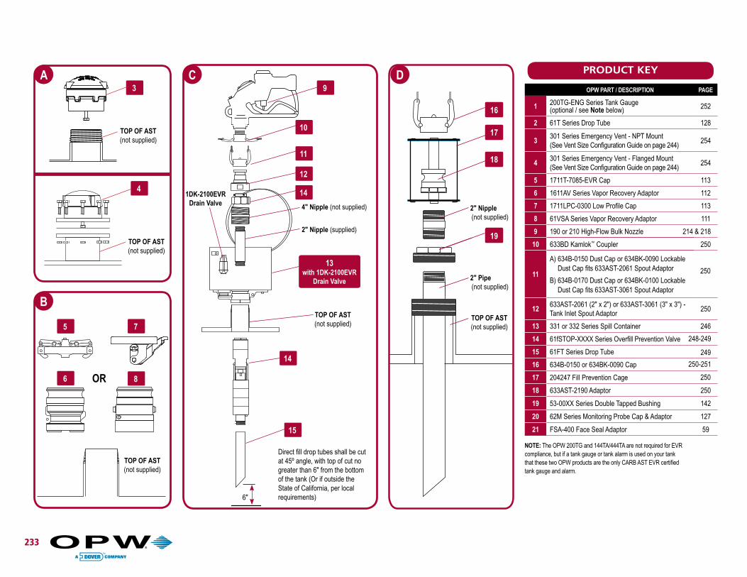
Direct fill drop tubes shall be cut at 45º angle, with top of cut no greater than 6" from the bottom of the tank (Or if outside the State of California, per local requirements)
C D
2" Nipple(not supplied)
2" Pipe(not supplied)
TOP OF AST(not supplied)
19
4" Nipple (not supplied)
2" Nipple (supplied)
B3
A
4
5
6 8
7
TOP OF AST(not supplied)
B
OR
6"
TOP OF AST(not supplied)
TOP OF AST(not supplied)
NOTE: The OPW 200TG and 144TA/444TA are not required for EVRcompliance, but if a tank gauge or tank alarm is used on your tankthat these two OPW products are the only CARB AST EVR certifiedtank gauge and alarm.
OPW PART / DESCRIPTION PAGE
1 200TG-ENG Series Tank Gauge (optional / see Note below) 252
2 61T Series Drop Tube 128
3301 Series Emergency Vent - NPT Mount(See Vent Size Configuration Guide on page 244)
254
4301 Series Emergency Vent - Flanged Mount(See Vent Size Configuration Guide on page 244)
254
5 1711T-7085-EVR Cap 113
6 1611AV Series Vapor Recovery Adaptor 112
7 1711LPC-0300 Low Profile Cap 113
8 61VSA Series Vapor Recovery Adaptor 111
9 190 or 210 High-Flow Bulk Nozzle 214 & 218
10 633BD Kamlok™ Coupler 250
11
A) 634B-0150 Dust Cap or 634BK-0090 Lockable Dust Cap fits 633AST-2061 Spout Adaptor
B) 634B-0170 Dust Cap or 634BK-0100 Lockable Dust Cap fits 633AST-3061 Spout Adaptor
12633AST-2061 (2" x 2") or 633AST-3061 (3" x 3") - Tank Inlet Spout Adaptor
250
13 331 or 332 Series Spill Container 246
14 61fSTOP-XXXX Series Overfill Prevention Valve
15 61FT Series Drop Tube
16 634B-0150 or 634BK-0090 Cap
17 204247 Fill Prevention Cage
18 633AST-2190 Adaptor 250
19 53-00XX Series Double Tapped Bushing 142
20 62M Series Monitoring Probe Cap & Adaptor 127
21 FSA-400 Face Seal Adaptor 59
250
249
250
248-249
250-251
PRODUCT KEY
1
2 3
24
234 Above Ground Storage Tank - Remote Fill - Remote Dispensing Typical Non-EVR Remote Fill / Remote Dispensing AST Application
1
2
5
3 4 27
2818
24
A D
B
C
To P
ress
ure
Vacu
um V
ent
Vapor Return
Fill Pipe
TOP OF AST(not supplied)
2" Nipple(not supplied)
Fill Pipe
235
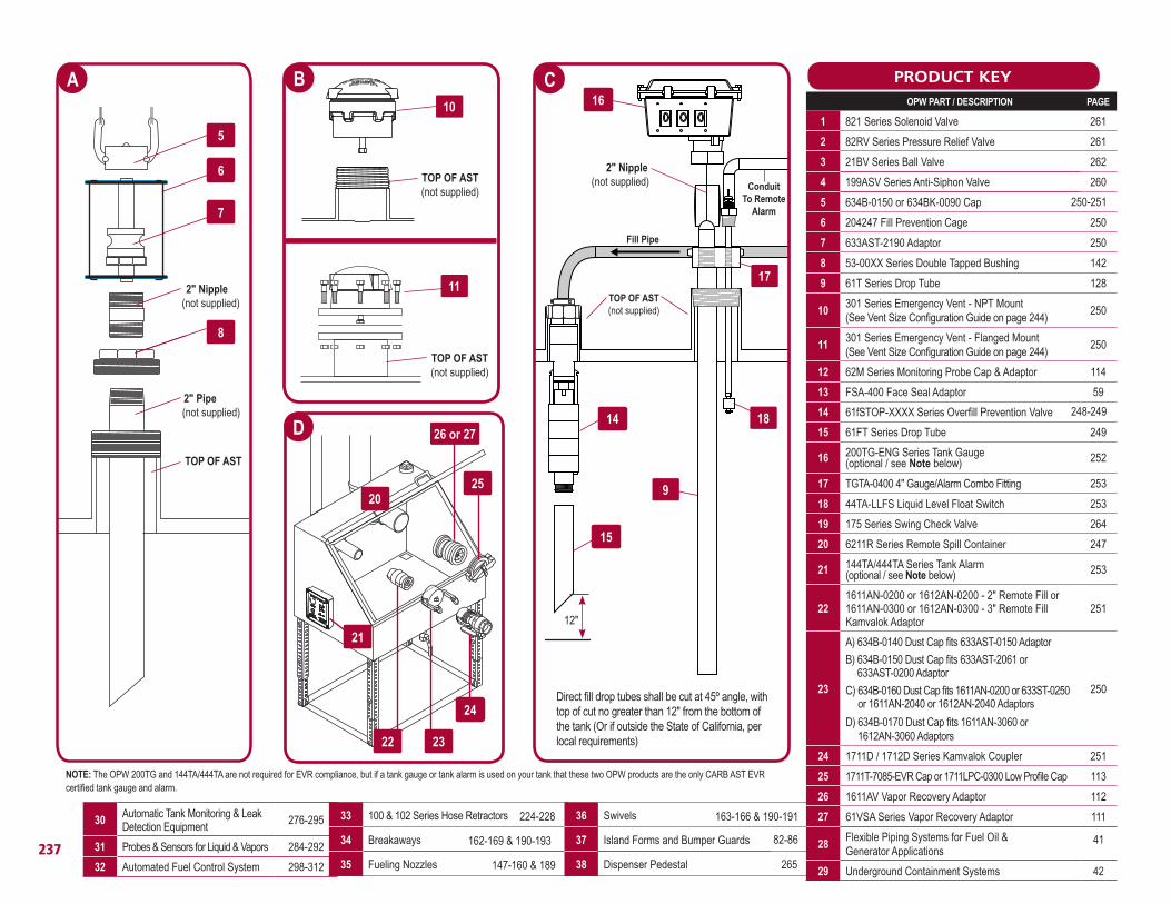
KEY OPW PART / DESCRIPTION PAGE
1 178S Series Emergency Valve 263
2 821 Series Solenoid Valve 261
3 21BV Series Ball Valve 262
4 199ASV Series Anti-Siphon Valve 260
5 82RV Series Pressure Relief Valve 261
6 53-00XX Series Double Tapped Bushing 127
7 634B-0150 or 634BK-0090 Cap
8 204247 Fill Prevention Cage 250
9 633AST-2190 Adaptor 250
10301 Series Emergency Vent - Threaded Mount (See Vent Size Configuration Guide on page 244)
254
11301 Series Emergency Vent - Flanged Mount(See Vent Size Configuration Guide on page 244)
254
12 61fSTOP-XXXX Series Overfill Prevention Valve
13 61FT Series Drop Tube 249
14200TG-ENG Series Tank Gauge (optional / see Note below)
201611AN-0200 or 1612AN-0200 - 2" Remote Fill or 1611AN-0300 or 1612AN-0300 - 3" Remote Fill Kamvalok Adaptor
251
21
A) 634B-0140 Dust Cap fits 633AST-0150 Adaptor
B) 634B-0150 Dust Cap fits 633AST-2061 or 633AST-0200 Adaptor
C) 634B-0160 Dust Cap fits 1611AN-0200 or 633ST-0250 or 1611AN-2040 or 1612AN-2040 Adaptors
D) 634B-0170 Dust Cap fits 1611AN-3060 or 1612AN-3060 Adaptors
250
22 1711D / 1712D Series Kamvalok Coupler 251
23 1711T-7085-EVR Cap or 1711LPC-0300 Low Profile Cap 113
24 144TA/444TA Series Tank Alarm(optional / see Note below) 253
25 1611AV Vapor Recovery Adaptor 112
26 61VSA Series Vapor Recovery Adaptor 111
27 62M Series Monitoring Probe Cap & Adaptor 114
28 FSA-400 Face Seal Adaptor 59
7
8
9
A C
2" Nipple(not supplied)
2" Pipe(not supplied)
TOP OF AST(not supplied)
6
16
17
24
20 21
22
1923
15
14
13
12
B PRODUCT KEY
Direct fill drop tubes shall be cut at 45º angle, with top of cut no greater than 12" from the bottom of the tank (Or if outside the State of California, per local requirements)
D
TOP OF AST(not supplied)
TOP OF AST(not supplied)
10
11
12"
Conduit To Remote
Alarm
25 or 26
NOTE: The OPW 200TG and 144TA/444TA are not required for EVR compliance, but if a tank gauge or tank alarm is used on your tank that these two OPW products are the only CARB AST EVR certified tank gauge and alarm.
248-249
250-251
To P
ress
ure
Vacu
um V
ent
236
A
B
28
3
1
D
4 19 30
21
32
C
31
31
3 12
13
29
2
Vapor Return
Fill Pipe
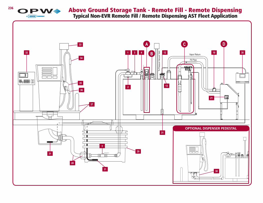
Above Ground Storage Tank - Remote Fill - Remote Dispensing Typical Non-EVR Remote Fill / Remote Dispensing AST Fleet Application
10301 Series Emergency Vent - NPT Mount(See Vent Size Configuration Guide on page 244)
250
11301 Series Emergency Vent - Flanged Mount(See Vent Size Configuration Guide on page 244)
250
12 62M Series Monitoring Probe Cap & Adaptor 114
13 FSA-400 Face Seal Adaptor 59
14 61fSTOP-XXXX Series Overfill Prevention Valve
15 61FT Series Drop Tube 249
16 200TG-ENG Series Tank Gauge (optional / see Note below) 252
17 TGTA-0400 4" Gauge/Alarm Combo Fitting 253
18 44TA-LLFS Liquid Level Float Switch 253
19 175 Series Swing Check Valve 264
20 6211R Series Remote Spill Container 247
21 144TA/444TA Series Tank Alarm(optional / see Note below) 253
221611AN-0200 or 1612AN-0200 - 2" Remote Fill or 1611AN-0300 or 1612AN-0300 - 3" Remote Fill Kamvalok Adaptor
251
23
A) 634B-0140 Dust Cap fits 633AST-0150 Adaptor
B) 634B-0150 Dust Cap fits 633AST-2061 or 633AST-0200 Adaptor
C) 634B-0160 Dust Cap fits 1611AN-0200 or 633ST-0250 or 1611AN-2040 or 1612AN-2040 Adaptors
D) 634B-0170 Dust Cap fits 1611AN-3060 or 1612AN-3060 Adaptors
250
24 1711D / 1712D Series Kamvalok Coupler 251
25 1711T-7085-EVR Cap or 1711LPC-0300 Low Profile Cap 113
26 1611AV Vapor Recovery Adaptor 112
27 61VSA Series Vapor Recovery Adaptor 111
28Flexible Piping Systems for Fuel Oil & Generator Applications
29 Underground Containment Systems 42
PRODUCT KEY
D
C
Direct fill drop tubes shall be cut at 45º angle, with top of cut no greater than 12" from the bottom of the tank (Or if outside the State of California, per local requirements)
16
17
18
9
14
15
2520
21
22 23
24
B
TOP OF AST(not supplied)
10
11
TOP OF AST(not supplied)
Fill Pipe
TOP OF AST(not supplied)
30 Automatic Tank Monitoring & Leak Detection Equipment 276-295
31 Probes & Sensors for Liquid & Vapors 284-292
32 Automated Fuel Control System 298-312
12"
2" Nipple(not supplied) Conduit
To Remote Alarm
26 or 27
250-251
248-249
41
33 100 & 102 Series Hose Retractors
34 Breakaways
35 Fueling Nozzles
36 Swivels
37 Island Forms and Bumper Guards
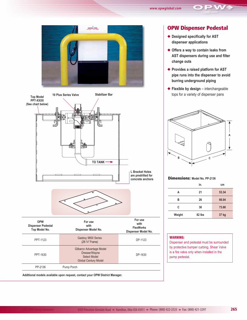
38 Dispenser Pedestal 265
82-86
224-228
162-169 & 190-193
147-160 & 189
163-166 & 190-191
NOTE: The OPW 200TG and 144TA/444TA are not required for EVR compliance, but if a tank gauge or tank alarm is used on your tank that these two OPW products are the only CARB AST EVR certified tank gauge and alarm.
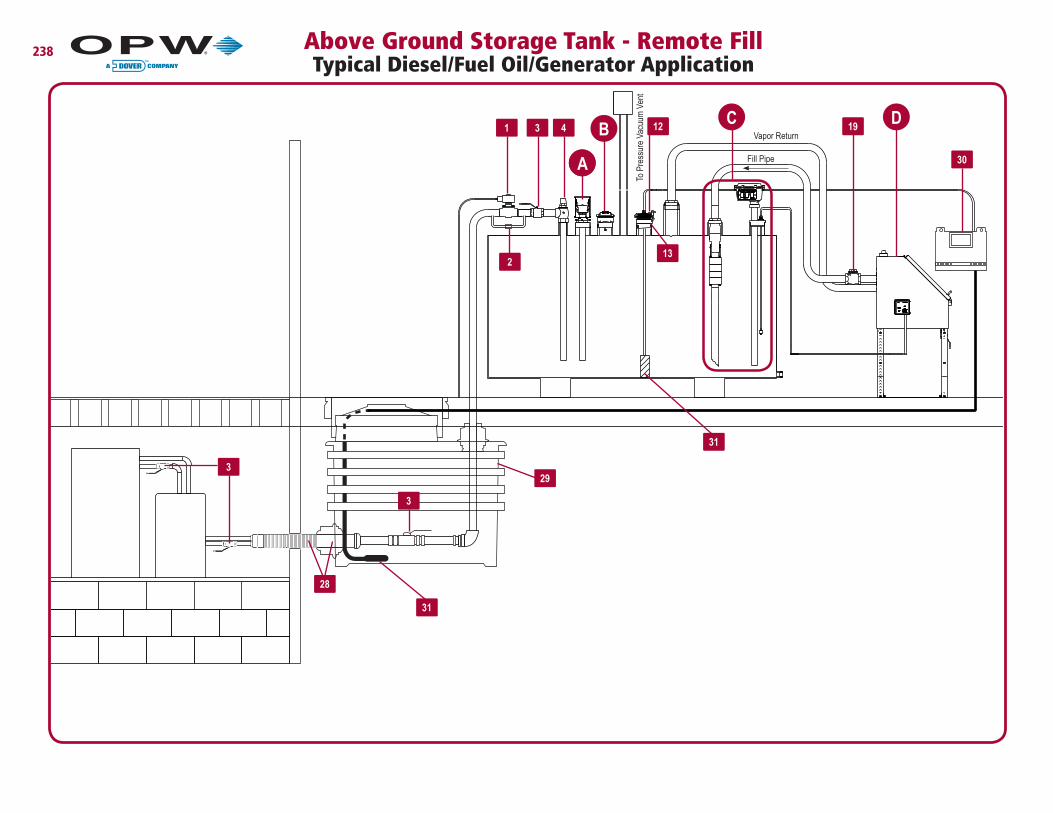
238 Above Ground Storage Tank - Remote Fill Typical Diesel/Fuel Oil/Generator Application
28
30
3
3
1
29
AA
BD
To P
ress
ure
Vacu
um V
ent
3
2
4 12
13
19Vapor Return
Fill Pipe
C
31
31
Direct fill drop tubes shall be cut at 45º angle, with top of cut no greater than 12" from the bottom of the tank (Or if outside the State of California, per local requirements)
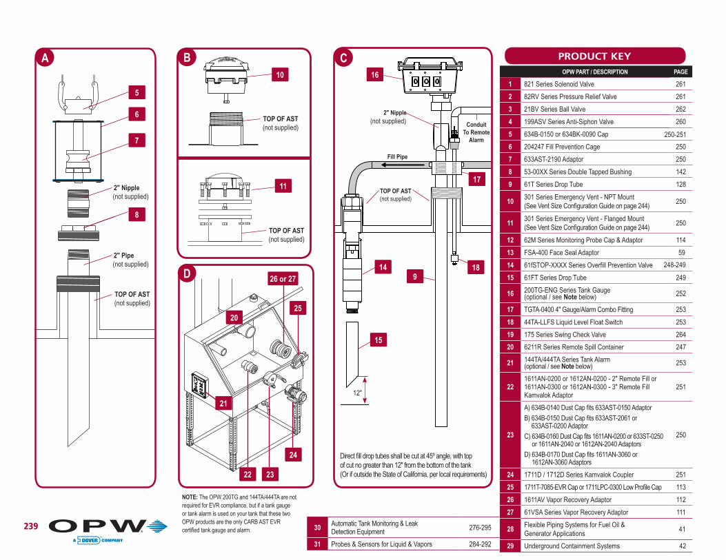
239
5
6
7
A
2" Nipple(not supplied)
2" Pipe(not supplied)
TOP OF AST(not supplied)
8
PRODUCT KEYB
TOP OF AST(not supplied)
D
2" Nipple(not supplied)
Fill Pipe
ConduitTo Remote
Alarm
TOP OF AST(not supplied)
C16
17
18 9
14
15
26 or 27
2520
21
22 23
24
NOTE: The OPW 200TG and 144TA/444TA are not required for EVR compliance, but if a tank gauge or tank alarm is used on your tank that these two OPW products are the only CARB AST EVR certified tank gauge and alarm.
11
TOP OF AST(not supplied)
12"
OPW PART / DESCRIPTION PAGE
1 821 Series Solenoid Valve 261
2 82RV Series Pressure Relief Valve 261
3 21BV Series Ball Valve 262
4 199ASV Series Anti-Siphon Valve 260
5 634B-0150 or 634BK-0090 Cap
6 204247 Fill Prevention Cage 250
7 633AST-2190 Adaptor 250
8 53-00XX Series Double Tapped Bushing 142
9 61T Series Drop Tube 128
10301 Series Emergency Vent - NPT Mount(See Vent Size Configuration Guide on page 244)
250
11301 Series Emergency Vent - Flanged Mount(See Vent Size Configuration Guide on page 244)
250
12 62M Series Monitoring Probe Cap & Adaptor 114
13 FSA-400 Face Seal Adaptor 59
14 61fSTOP-XXXX Series Overfill Prevention Valve
15 61FT Series Drop Tube 249
16 200TG-ENG Series Tank Gauge (optional / see Note below) 252
17 TGTA-0400 4" Gauge/Alarm Combo Fitting 253
18 44TA-LLFS Liquid Level Float Switch 253
19 175 Series Swing Check Valve 264
20 6211R Series Remote Spill Container 247
21 144TA/444TA Series Tank Alarm(optional / see Note below) 253
221611AN-0200 or 1612AN-0200 - 2" Remote Fill or 1611AN-0300 or 1612AN-0300 - 3" Remote Fill Kamvalok Adaptor
251
23
A) 634B-0140 Dust Cap fits 633AST-0150 Adaptor B) 634B-0150 Dust Cap fits 633AST-2061 or
633AST-0200 AdaptorC) 634B-0160 Dust Cap fits 1611AN-0200 or 633ST-0250
or 1611AN-2040 or 1612AN-2040 AdaptorsD) 634B-0170 Dust Cap fits 1611AN-3060 or
1612AN-3060 Adaptors
250
24 1711D / 1712D Series Kamvalok Coupler 251
25 1711T-7085-EVR Cap or 1711LPC-0300 Low Profile Cap 113
26 1611AV Vapor Recovery Adaptor 112
27 61VSA Series Vapor Recovery Adaptor 111
28Flexible Piping Systems for Fuel Oil & Generator Applications
29 Underground Containment Systems 42
30 Automatic Tank Monitoring & Leak Detection Equipment 276-295
31 Probes & Sensors for Liquid & Vapors 284-292
250-251
248-249
41
10
D*C
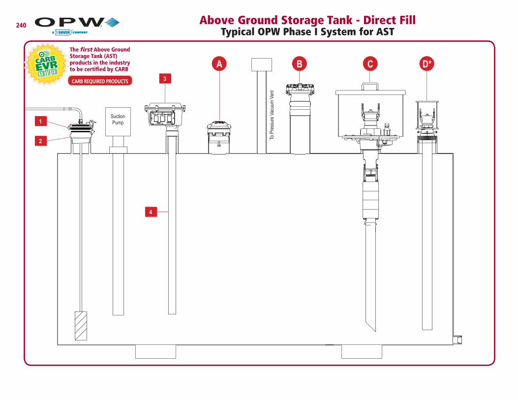
240 Above Ground Storage Tank - Direct Fill Typical OPW Phase I System for AST
3
1
2
4
Suction Pump
A B
To P
ress
ure
Vacu
um V
ent
CARB REQUIRED PRODUCTS
The first Above Ground Storage Tank (AST) products in the industry to be certified by CARB
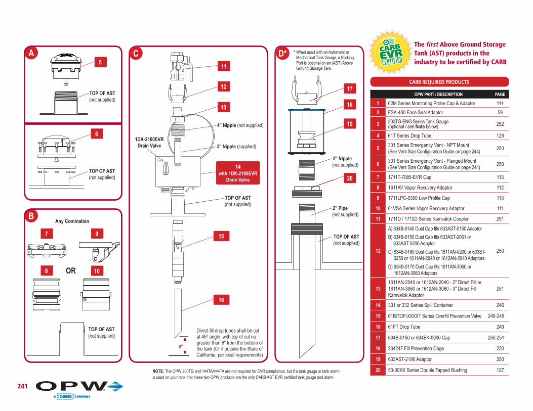
241
TOP OF AST(not supplied)
1DK-2100EVR Drain Valve
17
18
19
11
12
13
15
16
14 with 1DK-2100EVR
Drain Valve
Direct fill drop tubes shall be cut at 45º angle, with top of cut no greater than 6" from the bottom of the tank (Or if outside the State of California, per local requirements)
C D*
2" Nipple(not supplied)
2" Pipe(not supplied)
TOP OF AST(not supplied)
20
4" Nipple (not supplied)
2" Nipple (supplied)
OPW PART / DESCRIPTION PAGE
1 62M Series Monitoring Probe Cap & Adaptor 114
2 FSA-400 Face Seal Adaptor 59
3 200TG-ENG Series Tank Gauge (optional / see Note below) 252
4 61T Series Drop Tube 128
5301 Series Emergency Vent - NPT Mount(See Vent Size Configuration Guide on page 244)
250
6301 Series Emergency Vent - Flanged Mount(See Vent Size Configuration Guide on page 244)
250
7 1711T-7085-EVR Cap 113
8 1611AV Vapor Recovery Adaptor 112
9 1711LPC-0300 Low Profile Cap 113
10 61VSA Series Vapor Recovery Adaptor 111
11 1711D / 1712D Series Kamvalok Coupler 251
12
A) 634B-0140 Dust Cap fits 633AST-0150 Adaptor
B) 634B-0150 Dust Cap fits 633AST-2061 or 633AST-0200 Adaptor
C) 634B-0160 Dust Cap fits 1611AN-0200 or 633ST-0250 or 1611AN-2040 or 1612AN-2040 Adaptors
D) 634B-0170 Dust Cap fits 1611AN-3060 or 1612AN-3060 Adaptors
250
131611AN-2040 or 1612AN-2040 - 2" Direct Fill or 1611AN-3060 or 1612AN-3060 - 3" Direct Fill Kamvalok Adaptor
251
14 331 or 332 Series Spill Container 246
15 61fSTOP-XXXXT Series Overfill Prevention Valve
16 61FT Drop Tube 249
17 634B-0150 or 634BK-0090 Cap
18 204247 Fill Prevention Cage 250
19 633AST-2190 Adaptor 250
20 53-00XX Series Double Tapped Bushing 127
A
6
TOP OF AST(not supplied)
NOTE: The OPW 200TG and 144TA/444TA are not required for EVR compliance, but if a tank gauge or tank alarm is used on your tank that these two OPW products are the only CARB AST EVR certified tank gauge and alarm.
CARB REQUIRED PRODUCTS
The first Above Ground Storage Tank (AST) products in the industry to be certified by CARB5
TOP OF AST(not supplied)
6"
7
8 10
9
TOP OF AST(not supplied)
B
OR
Any Comination
250-251
248-249
* When used with an Automatic or Mechanical Tank Gauge, a Sticking Port is optional on an (AST) Above Ground Storage Tank.
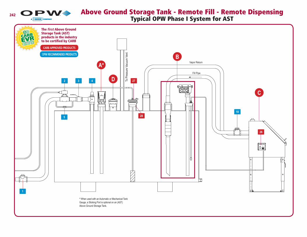
242 Above Ground Storage Tank - Remote Fill - Remote Dispensing Typical OPW Phase I System for AST
27
26
To P
ress
ure
Vacu
um V
ent
A*B
D
C
OPW RECOMMENDED PRODUCTS
CARB APPROVED PRODUCTS
The first Above Ground Storage Tank (AST) products in the industry to be certified by CARB
5
18
3 42
1
Fill Pipe
Vapor Return
28
* When used with an Automatic or Mechanical Tank Gauge, a Sticking Port is optional on an (AST) Above Ground Storage Tank.
27 62M Series Monitoring Probe Cap & Adaptor 114
28 FSA-400 Face Seal Adaptor 59
243
7
8
9
A* C
2" Nipple(not supplied)
2" Pipe(not supplied)
TOP OF AST(not supplied)
6
1626
20 21
22
1925
14
15
13
12
6
B
D
Direct fill drop tubes shall be cut at 45º angle, with top of cut no greater than 12" from the bottom of the tank (Or if outside the State of California, per local requirements)
KEY OPW PART / DESCRIPTION PAGE
1 178S Series Emergency Valve (optional) 300
2 821 Series Solenoid Valve (optional) 298
3 21BV Series Ball Valve (optional) 298
4 199ASV Series Anti-Siphon Valve (optional) 297
5 82RV Series Pressure Relief Valve (optional) 298
6 53-00XX Series Double Tapped Bushing (optional) 127
7 634B-0150 or 634BK-0900 Cap
8 204247 Fill Prevention Cage 250
9 633AST-2190 Adaptor 250
10301 Series Emergency Vent - Threaded Mount (See Vent Size Configuration Guide on page 244)
250
11301 Series Emergency Vent - Flanged Mount(See Vent Size Configuration Guide on page 244)
250
12 61fSTOP-XXXXT Series Overfill Prevention Valve
13 61FT Series Drop Tube 249
14 61T Series Drop Tube 128
15200TG-ENG Series Tank Gauge (optional / see Note below)
201611AN-0200 or 1612AN-0200 - 2" Remote Fill or 1611AN-0300 or 1612AN-0300 - 3" Remote Fill Kamvalok Adaptor
251
21
A) 634B-0140 Dust Cap fits 633AST-0150 Adaptor
B) 634B-0150 Dust Cap fits 633AST-2061 or 633AST-0200 Adaptor
C) 634B-0160 Dust Cap fits 1611AN-0200 or 633ST-0250 or 1611AN-2040 or 1612AN-2040 Adaptors
D) 634B-0170 Dust Cap fits 1611AN-3060 or 1612AN-3060 Adaptors
250
22 1711D, 1711DL, 1712D, 1712DL Series Kamvalok Couplers 251
23 1611AV Vapor Recovery Adaptor 112
24 61VSA Series Vapor Recovery Adaptor 111
25 1711T-7085-EVR Cap or 1711LPC-0300 Low Profile Cap 113
26 144TA/444TA Series Tank Alarm (optional / see NOTE below) 253
NOTE: The OPW 200TG and 144TA/444TA are not required for EVR compliance, but if a tank gauge or tank alarm is used on your tank that these two OPW products are the only CARB AST EVR certified tank gauge and alarm.
When used with an Automatic or Mechanical Tank Gauge, a Sticking Port is optional on an (AST) Above Ground Storage Tank.
RECOMMENDED PRODUCTSAPPROVED PRODUCTS
The first Above Ground Storage Tank (AST) products in the industry to be certified by CARB
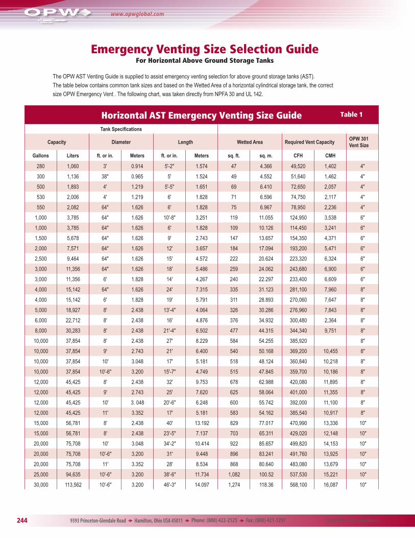
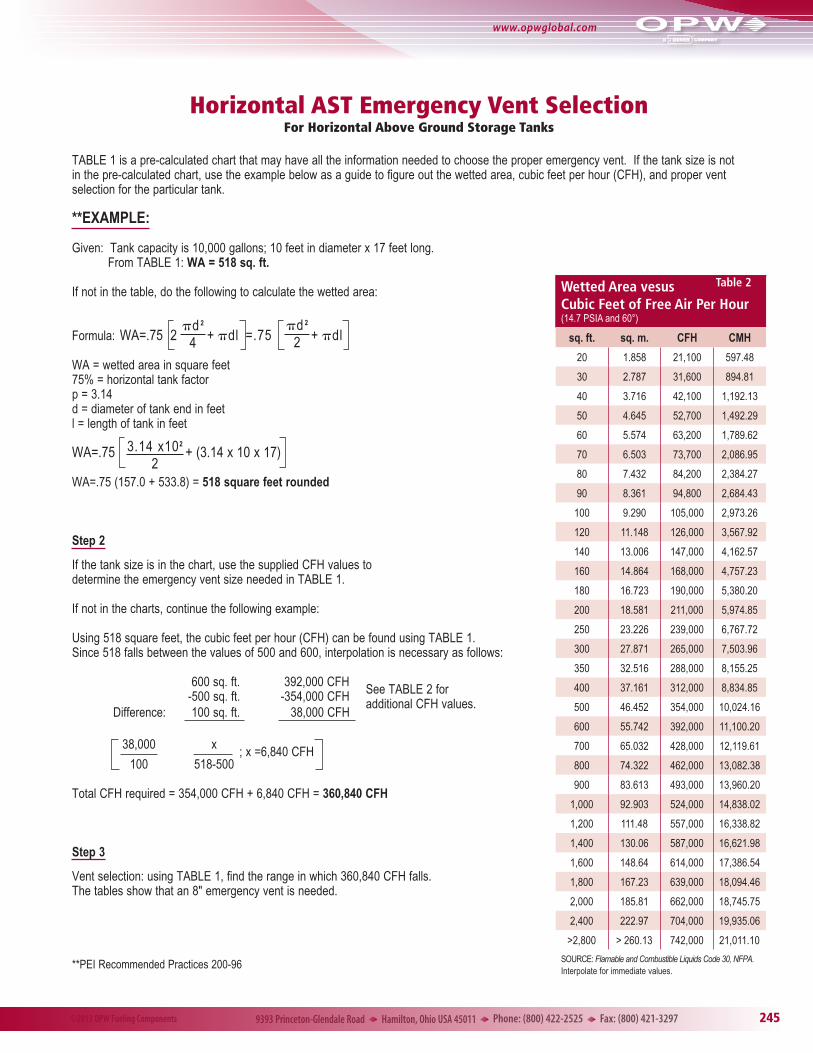
TABLE 1 is a pre-calculated chart that may have all the information needed to choose the proper emergency vent. If the tank size is not in the pre-calculated chart, use the example below as a guide to figure out the wetted area, cubic feet per hour (CFH), and proper vent selection for the particular tank.
**EXAMPLE:
Given: Tank capacity is 10,000 gallons; 10 feet in diameter x 17 feet long.Table 2From TABLE 1: WA = 518 sq. ft.
If not in the table, do the following to calculate the wetted area:
Formula: WA=.75 2 + pdl =.75 + pdl
WA = wetted area in square feet75% = horizontal tank factorp = 3.14d = diameter of tank end in feetl = length of tank in feet
WA=.75 + (3.14 x 10 x 17) WA=.75 (157.0 + 533.8) = 518 square feet rounded
Step 2
If the tank size is in the chart, use the supplied CFH values to determine the emergency vent size needed in TABLE 1.
If not in the charts, continue the following example:
Using 518 square feet, the cubic feet per hour (CFH) can be found using TABLE 1. Since 518 falls between the values of 500 and 600, interpolation is necessary as follows:
600 sq. ft. 392,000 CFH -500 sq. ft. -354,000 CFH Difference: 100 sq. ft. 38,000 CFH
uEasy Installation – 4" NPT threaded base screws directly to the tank riser pipe. No further adjustments are needed.
uIntegral Drain Valve – allows high-speed drainage of spilled product back into the tank.
uCapacity – available in 7-gallon (26.5 liter) container capacity. Larger 7-gallon capacity spill containers provide additional clearance for 61ƒSTOP Overfill Prevention Valves (3.5 gallon-221 only).
uRain-Shedding Cover Design – hooded cover design helps prevent water or snow entry by extending the lip of the cover over the body of the spill container.
uWelded-Hinge, Lockable Hatch – the cover includes a provision for a padlock and a welded-hinge assembly for added security.
u12 Gauge Epoxy-Powder Coated Construction – heavy-duty materials, compatible with hydrocarbons, for long service life and added security
u332AST Spun Steel Design – spun steel construction provides a lightweight, one-piece design for easy installation and a clean, sleek appearance on above ground tanks.
u6211AST Heavyweight, Welded Base Design – Thick, welded steel base and 12-gauge steel walls provide solid strength for heavy-duty applications.
uAll Models Are ULC Listed – clearly labeled to identify the listing.
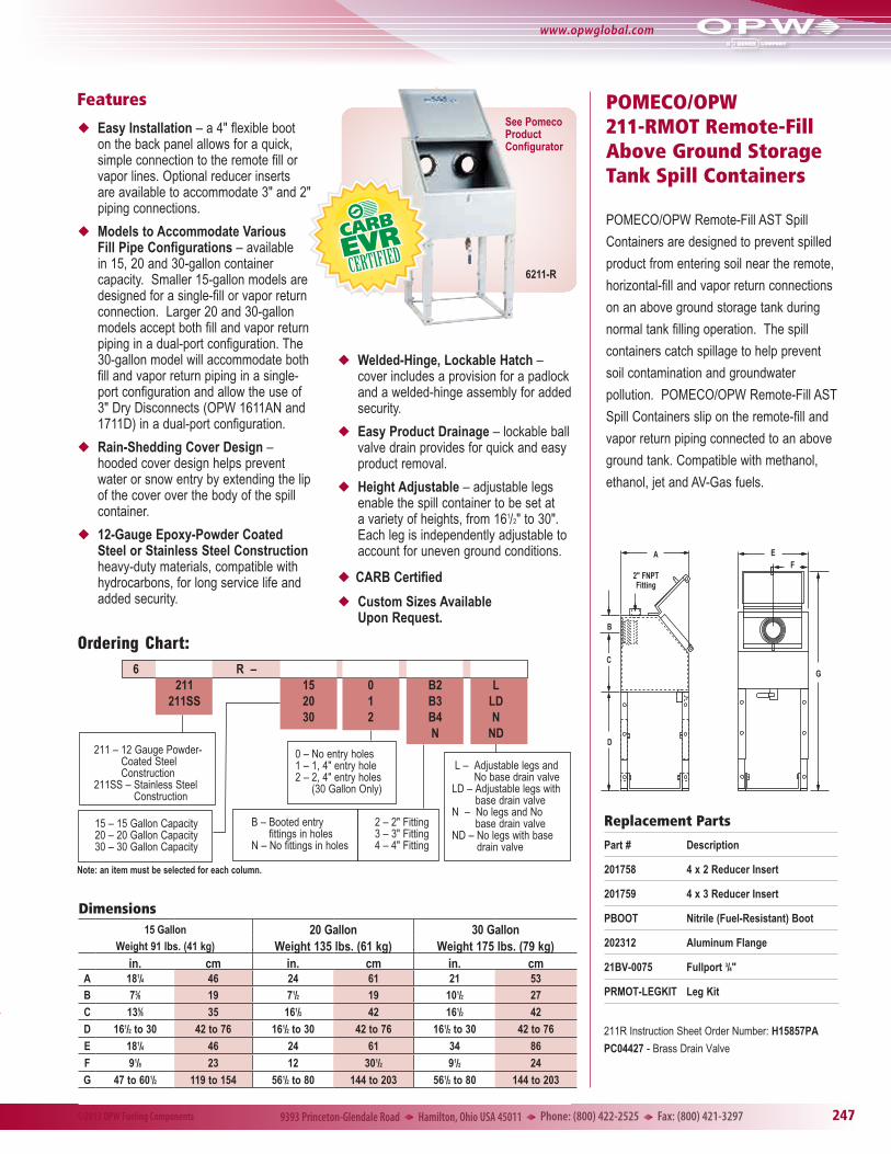
POMECO/OPW 211-RMOT Remote-Fill Above Ground Storage Tank Spill Containers
POMECO/OPW Remote-Fill AST Spill
Containers are designed to prevent spilled
product from entering soil near the remote,
horizontal-fill and vapor return connections
on an above ground storage tank during
normal tank filling operation. The spill
containers catch spillage to help prevent
soil contamination and groundwater
pollution. POMECO/OPW Remote-Fill AST
Spill Containers slip on the remote-fill and
vapor return piping connected to an above
ground tank. Compatible with methanol,
ethanol, jet and AV-Gas fuels.
D
C
B
A
2" FNPTFitting
FE
G
Features
u Easy Installation – a 4" flexible boot on the back panel allows for a quick, simple connection to the remote fill or vapor lines. Optional reducer inserts are available to accommodate 3" and 2" piping connections.
u Models to Accommodate Various Fill Pipe Configurations – available in 15, 20 and 30-gallon container capacity. Smaller 15-gallon models are designed for a single-fill or vapor return connection. Larger 20 and 30-gallon models accept both fill and vapor return piping in a dual-port configuration. The 30-gallon model will accommodate both fill and vapor return piping in a single-port configuration and allow the use of 3" Dry Disconnects (OPW 1611AN and 1711D) in a dual-port configuration.
u Rain-Shedding Cover Design – hooded cover design helps prevent water or snow entry by extending the lip of the cover over the body of the spill container.
u 12-Gauge Epoxy-Powder Coated Steel or Stainless Steel Construction heavy-duty materials, compatible with hydrocarbons, for long service life and added security.
u Welded-Hinge, Lockable Hatch – cover includes a provision for a padlock and a welded-hinge assembly for added security.
u Easy Product Drainage – lockable ball valve drain provides for quick and easy product removal.
u Height Adjustable – adjustable legs enable the spill container to be set at a variety of heights, from 161/2" to 30". Each leg is independently adjustable to account for uneven ground conditions.
uCARB Certified
u Custom Sizes Available Upon Request.
Dimensions15 Gallon 20 Gallon 30 Gallon
Weight 91 lbs. (41 kg) Weight 135 lbs. (61 kg) Weight 175 lbs. (79 kg)in. cm in. cm in. cm
A 181/4 46 24 61 21 53B 73⁄8 19 71/2 19 101/2 27
C 135⁄8 35 161/2 42 161/2 42
D 161/2 to 30 42 to 76 161/2 to 30 42 to 76 161/2 to 30 42 to 76E 181/4 46 24 61 34 86
F 91/8 23 12 301/2 91/2 24
G 47 to 601/2 119 to 154 561/2 to 80 144 to 203 561/2 to 80 144 to 203
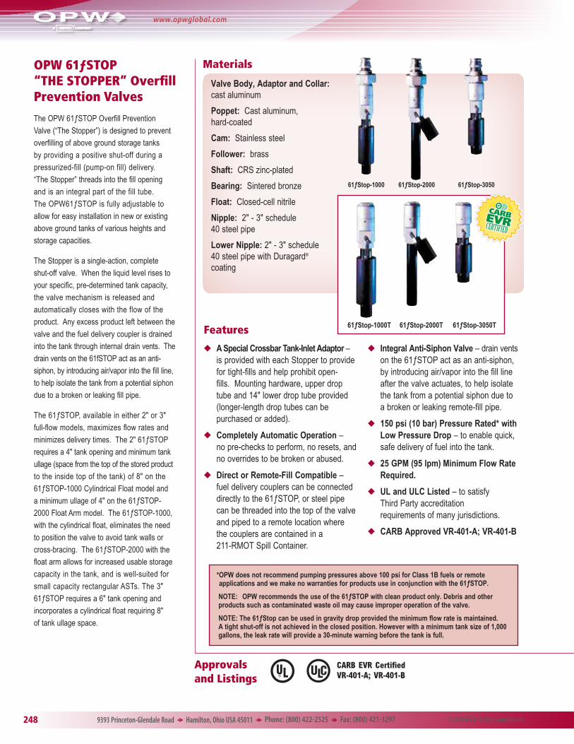
OPW 61ƒSTOP “THE STOPPER” Overfill Prevention Valves
The OPW 61ƒSTOP Overfill Prevention
Valve (“The Stopper”) is designed to prevent
overfilling of above ground storage tanks
by providing a positive shut-off during a
pressurized-fill (pump-on fill) delivery.
“The Stopper” threads into the fill opening
and is an integral part of the fill tube.
The OPW61ƒSTOP is fully adjustable to
allow for easy installation in new or existing
above ground tanks of various heights and
storage capacities.
The Stopper is a single-action, complete
shut-off valve. When the liquid level rises to
your specific, pre-determined tank capacity,
the valve mechanism is released and
automatically closes with the flow of the
product. Any excess product left between the
valve and the fuel delivery coupler is drained
into the tank through internal drain vents. The
drain vents on the 61fSTOP act as an anti-
siphon, by introducing air/vapor into the fill line,
to help isolate the tank from a potential siphon
due to a broken or leaking fill pipe.
The 61ƒSTOP, available in either 2" or 3"
full-flow models, maximizes flow rates and
minimizes delivery times. The 2" 61ƒSTOP
requires a 4" tank opening and minimum tank
ullage (space from the top of the stored product
to the inside top of the tank) of 8" on the
61ƒSTOP-1000 Cylindrical Float model and
a minimum ullage of 4" on the 61ƒSTOP-
2000 Float Arm model. The 61ƒSTOP-1000,
with the cylindrical float, eliminates the need
to position the valve to avoid tank walls or
cross-bracing. The 61ƒSTOP-2000 with the
float arm allows for increased usable storage
capacity in the tank, and is well-suited for
small capacity rectangular ASTs. The 3"
61ƒSTOP requires a 6" tank opening and
incorporates a cylindrical float requiring 8"
of tank ullage space.
61ƒStop-1000 61ƒStop-3050
u A Special Crossbar Tank-Inlet Adaptor – is provided with each Stopper to provide for tight-fills and help prohibit open-fills. Mounting hardware, upper drop tube and 14" lower drop tube provided (longer-length drop tubes can be purchased or added).
u Completely Automatic Operation – no pre-checks to perform, no resets, and no overrides to be broken or abused.
u Direct or Remote-Fill Compatible – fuel delivery couplers can be connected directly to the 61ƒSTOP, or steel pipe can be threaded into the top of the valve and piped to a remote location where the couplers are contained in a 211-RMOT Spill Container.
u Integral Anti-Siphon Valve – drain vents on the 61ƒSTOP act as an anti-siphon, by introducing air/vapor into the fill line after the valve actuates, to help isolate the tank from a potential siphon due to a broken or leaking remote-fill pipe.
u 150 psi (10 bar) Pressure Rated* with Low Pressure Drop – to enable quick, safe delivery of fuel into the tank.
u 25 GPM (95 lpm) Minimum Flow Rate Required.
u UL and ULC Listed – to satisfy Third Party accreditation requirements of many jurisdictions.
* OPW does not recommend pumping pressures above 100 psi for Class 1B fuels or remote applications and we make no warranties for products use in conjunction with the 61ƒSTOP.
NOTE: OPW recommends the use of the 61ƒSTOP with clean product only. Debris and other products such as contaminated waste oil may cause improper operation of the valve.
NOTE: The 61ƒStop can be used in gravity drop provided the minimum flow rate is maintained. A tight shut-off is not achieved in the closed position. However with a minimum tank size of 1,000 gallons, the leak rate will provide a 30-minute warning before the tank is full.
OPW 61FT Drop TubeThe OPW 61FT Drop Tube is designed to install on the bottom of the 61ƒSTOP AST Overfill Prevention Valves when a lightweight, longer, lower drop tube is required. Constructed of extruded aluminum, the OPW 61FT is connected to the bottom of the 61ƒSTOP by a clevis and cotter pin assembly, and allows for submerged filling of ASTs.
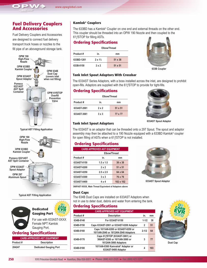
Fuel Delivery Couplers And AccessoriesFuel Delivery Couplers and Accessories are designed to connect fuel delivery transport truck hoses or nozzles to the fill pipe of an aboveground storage tank.
633B Coupler
Kamlok® Couplers
The 633BD has a Kamlok® Coupler on one end and external threads on the other end. This coupler should be threaded into an OPW 190 Nozzle and then coupled to the 61ƒSTOP for filling ASTs.
Ordering SpecificationsElbow/Thread
Product # in. mm
633BD-1261 2 x 11/2 51 x 38
633B-0150 2 x 2 51 x 51
633AST Spout Adaptor
Ordering SpecificationsElbow/Thread
Product # in. mm
633AST-2061 2 x 2 51 x 51
633AST-3061 3 x 3 77 x 77
Tank Inlet Spout Adaptors With Crossbar
The 633AST Series Adaptors, with a boss installed across the inlet, are designed to prohibit open-fills. Adaptors are supplied with the 61ƒSTOP to provide for tight-fills.
633AST Spout Adaptor
Tank Inlet Spout Adaptors
The 633AST is an adaptor that can be threaded onto a 297 Spout. The spout and adaptor assembly may then be attached to a 190 Nozzle equipped with a 633BD Kamlok® coupler for open filling of ASTs when a 61ƒSTOP is not installed.
Dust CapsThe 634B Dust Caps are installed on 633AST Adaptors when not in use to deter dust, debris and water from entering the tank.
Dedicated Gauging Port
For use with 633AST-0XXXFemale NPT Kamlok Gauging Port.
Lockable Dust CapsThe 634BK-0090 is a 2" lockable dust cap for the 61ƒSTOP. It will cap off any 2" 633AST Tank Inlet Spout Adaptor and offers the added feature of being lockable.
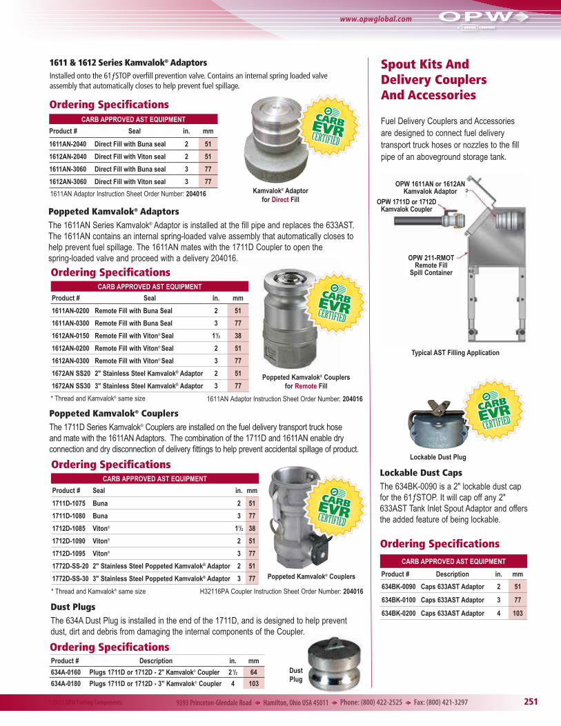
Fuel Delivery Couplers and Accessories are designed to connect fuel delivery transport truck hoses or nozzles to the fill pipe of an aboveground storage tank.
Poppeted Kamvalok® AdaptorsThe 1611AN Series Kamvalok® Adaptor is installed at the fill pipe and replaces the 633AST. The 1611AN contains an internal spring-loaded valve assembly that automatically closes to help prevent fuel spillage. The 1611AN mates with the 1711D Coupler to open the spring-loaded valve and proceed with a delivery 204016.
1611 & 1612 Series Kamvalok® AdaptorsInstalled onto the 61ƒSTOP overfill prevention valve. Contains an internal spring loaded valve assembly that automatically closes to help prevent fuel spillage.
Poppeted Kamvalok® CouplersThe 1711D Series Kamvalok® Couplers are installed on the fuel delivery transport truck hose and mate with the 1611AN Adaptors. The combination of the 1711D and 1611AN enable dry connection and dry disconnection of delivery fittings to help prevent accidental spillage of product.
Dust PlugsThe 634A Dust Plug is installed in the end of the 1711D, and is designed to help prevent dust, dirt and debris from damaging the internal components of the Coupler.
Ordering SpecificationsProduct # Description in. mm
The OPW 200TG Tank Gauge is designed for reading liquid levels in horizontal or vertical above ground storage tanks. The 200TG Tank Gauge provides an accurate numerical counter readout, eliminating the need for any on-site manual gauging.
u Vapor-Tight – allows for standard tank pressure testing and sealing up to 25-psig (1.72 bar).
u Angled Face – improves visibility from ground on large diameter tanks. May be read easily up to 30 feet away (9.14 m).
u Swivel Adaptor Base – allows for 360° of rotation of gauge face for easy viewing wherever needed.
u Easy Installation – 2" NPT-threaded base reduces labor time, and comes standard with female thread. A H11421RS may be purchased for male threaded applications.
u Corrosion-Resistant Construction – powder-coated die cast-aluminum body assures for long service life in many fluids.
u Drop Tube – prevents float entanglement in the tank, and gives the gauge a more accurate reading when turbulence is present (Drop Tubes sold separately. They are recommended for use in tanks with high turbulence, and where other piping and structures inside the tank may cause entanglement).
u Float Buoyancy – designed to float in all approved fuels with a specific gravity of 0.65 and greater.
u Tank Height – unit designed for use on any horizontal or vertical aboveground tank up to 18 feet (5.5 m) in depth. Specials available upon request.
u Numbering – black letters on white background for ultimate contrast and better visibility. Characters stand over 1" (25 mm) tall.
u Unit Measurement – Can be purchased in metric units to read in meters, 1/10, 1/100, or in English units to read in feet and inches.
u Maintenance – No annual maintenance required.
u U.S. Patent No.: 6,523,404 - Other patents pending.
u Compatible Fuels– see chart on page 266.
uTemperature Rating – 120°F to -40°F (49°C to -40°C)
Underwriters Laboratory Listed UL Listing MH29367. Liquid level gauges which are intended to be used on above ground storage tanks and monitor the level of petroleum-based flammable or combustible fluids.
A
B
E
D
Features
Materials
Enclosure: Powder-coated aluminum
Swivel Base: Hard-coat aluminum
Float: 304 stainless steel
Lenses: Tempered borosilicate
Gears: Acetal
Gaskets & O-Rings: Nitrile®
All Hardware: Stainless steel
Accuracy: + or - 2"
Dimensions:in. cm
A 8 1/4 21
B 10 1/4 26
C 9 22.75
D 6 3/4 17.25
E 11/2 3.75
Replacement Parts:Part # Description
C05165M Float
H14358M Lens
H14909M Lid Gasket
Ordering Specifications:Product # Description lb. kg
200TG-ENG English Unit Tank Gauge up to 18 ft. 7.75 3.52
200TG-ENG40 English Unit Tank Gauge - 40 ft. 7.75 3.52
200TG-MET Metric Unit Tank Gauge up to 6 m 7.75 3.52
200TG-MET40 Metric Unit Tank Gauge - 10 m 7.75 3.52
(Ancillary Equipment)Product # Description lb. kg
H11421RS 2" NPT Male x Male Nipple 1.5 0.68
CARB CERTIFIED AST EQUIPMENT
61T-0208 2" Dia. x 8' Long Drop Tube 2.67 1.21
61T-0212 2" Dia. x 12' Long Drop Tube 4.00 1.81
61T-0216 2" Dia. x 16' Long Drop Tube 5.33 2.42
200TG
200TG Tank Gauge Instruction Sheet Order Number: H14912PA
*NOTE: When replacing the battery for the 144TA-0100, open the alarm box and locate the OPW number on the black battery module. If the number reads “C05346” then use the replacement part H15615M. If the number reads “144TA-0100” then use the replacement part 202891.
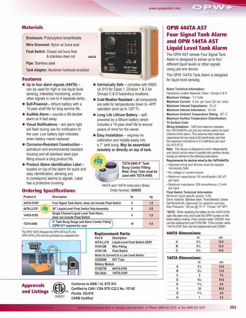
OPW 444TA AST Four Signal Tank Alarm and OPW 144TA AST Liquid Level Tank AlarmThe OPW AST remote Four Signal Tank Alarm is designed to sense up to four different liquid levels or other signals using just one device.
The OPW 144TA Tank Alarm is designed for liquid level sensing.
Alarm Technical Information:Hazardous Location Approval: Class I, Groups C & DMaximum Voltage: 7.2 VoltsMaximum Current: 8 ma. per input (32 ma. total)Maximum Internal Capacitance: 23 uFMaximum Internal Inductance: 33 mHMaximum Ambient Temperature Rating: 60° CMaximum Surface Temperature Classification:T4 Surface CodeWiring limitations: 1000 foot maximum between the 144TA/444TA unit and any remote switch for each channel of the alarm. This assumes that maximum capacitance for any input is 60 nanoFarads and that the maximum inductance is 0.2 milliHenry per input (UL-913 A7.3)Note: This device is designed to work independently and should not be wired in parallel with another device, except as defined in the following instructions. Requirements for devices wired to the 144TA/444TA:• Attached wiring and devices must be classed
Intrinsically Safe• No voltage or current source• Maximum capacitance: 60 nanoFarads (.06 uF)
per input• Maximum inductance: 200 microHenrys (.2 mH)
per inputFloat Switch Technical Information: Minimum liquid specific gravity: 0.45. Stem material: Stainless steel. Float Material: Closed Cell Buna-N (UL Approved) for gasoline services. Max Pressure: 150 psi @ 70° F. Thread 1/8" NPT.
Ordering Specifications:Product # Description lb. kg
444TA-0100* Four Signal Tank Alarm, does not include Float Switch 4 1.8
144TA-0100Single Channel Liquid Level Tank Alarm, does not include Float Switch
4 1.8
TGTA-04004" Tank Bung Gauge and Alarm Combo Fitting (OPW 61T required for use)
10 4.5
The OPW 144TA Requires the OPW 44TA-LLFS, the OPW 44TA-LLFS must be purchased as a separate item.
u Up to four alarm signals (444TA) – can be used for high or low liquid level sensing, interstitial monitoring, and/or other signals in one to 4 separate tanks.
uSelf-Powered – lithium battery with a 10-year shelf life for long service life.
u Audible Alarm – sounds a 90-decibel alarm at 4 feet away.
uVisual Notifications – red alarm light will flash during use for notification to the user. Low battery light indicates when battery needs replaced.
uCorrosion-Resistant Construction – petroleum and environmental resistant housing and all stainless steel pipe fitting ensure a long product life.
uProduct /Alarm Identification Label – located on top of the alarm for quick and easy identification, allowing you to correspond alarms to signals. Label has a protective covering.
u Intrinsically Safe – complies with ANSI/UL 913 for Class 1, Division 1 & 2 for Groups C & D hazardous locations.
u Cold Weather Resistant – all components are safe for temperatures down to -40ºF operation (and up to 120º F).
uLong Life Lithium Battery – self-powered by a lithium battery which includes a 10-year shelf life to ensure peace of mind for the owner.
u Easy Installation – requires no calibration and installs easily into a 1" tank bung. May be assembled remotely or directly on top of tank.
Features
Materials
Enclosure: Polybutylene terephthalate
Wire Grommet: Nylon w/ buna seal
Float Switch: Closed cell buna float & stainless steel rod
Pipe: Stainless steel
Tank Adaptor: Aluminum hardcoat anodized
Conforms to ANSI / UL STD 913Certified to CAN / CSA STD C22.2 No. 157-92Florida EQ-610CARB Certified
Replacement Parts:Part # Description44TA-LLFS Liquid-Level Float Switch ASSY H15412M Wire Fitting H15411M Float Switch Items to Convert to a Low Level Alarm:C05295M SST TubeBattery Module H15937M 444TA-0100See Note 144TA-0100*
444TA
Approvals and Listings
TGTA-0400 4" Tank Bung Combo FittingNote: Drop Tube must be used with TGTA-0400.
3069027
444TA and 144TA Instruction Sheet Order Number: 200655
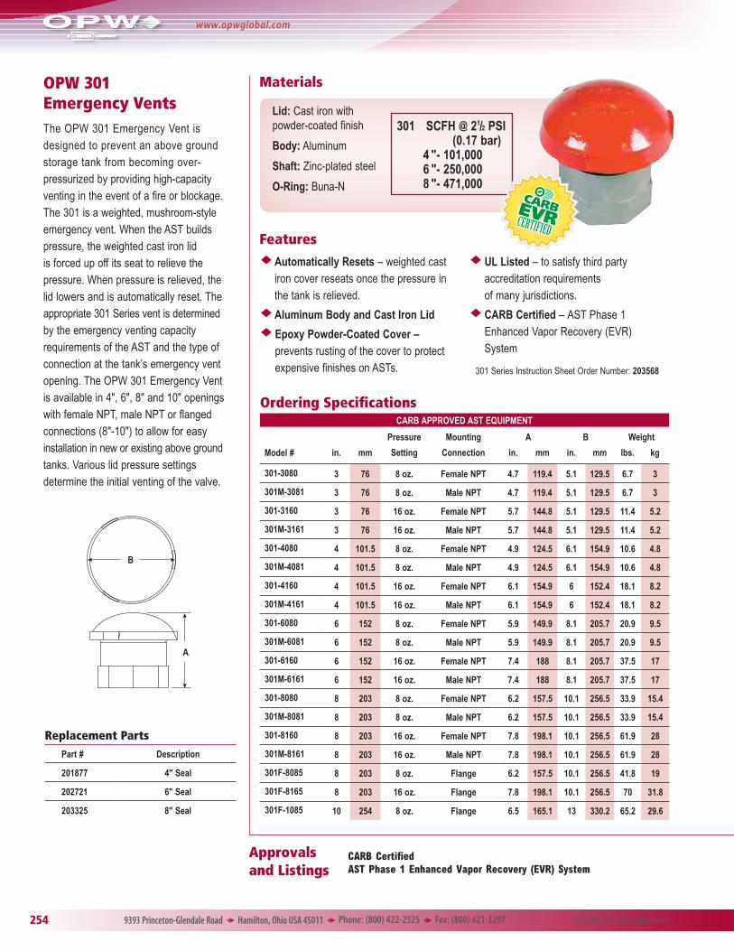
OPW 301 Emergency VentsThe OPW 301 Emergency Vent is designed to prevent an above ground storage tank from becoming over-pressurized by providing high-capacity venting in the event of a fire or blockage. The 301 is a weighted, mushroom-style emergency vent. When the AST builds pressure, the weighted cast iron lid is forced up off its seat to relieve the pressure. When pressure is relieved, the lid lowers and is automatically reset. The appropriate 301 Series vent is determined by the emergency venting capacity requirements of the AST and the type of connection at the tank’s emergency vent opening. The OPW 301 Emergency Vent is available in 4", 6", 8" and 10" openings with female NPT, male NPT or flanged connections (8"-10") to allow for easy installation in new or existing above ground tanks. Various lid pressure settings determine the initial venting of the valve.
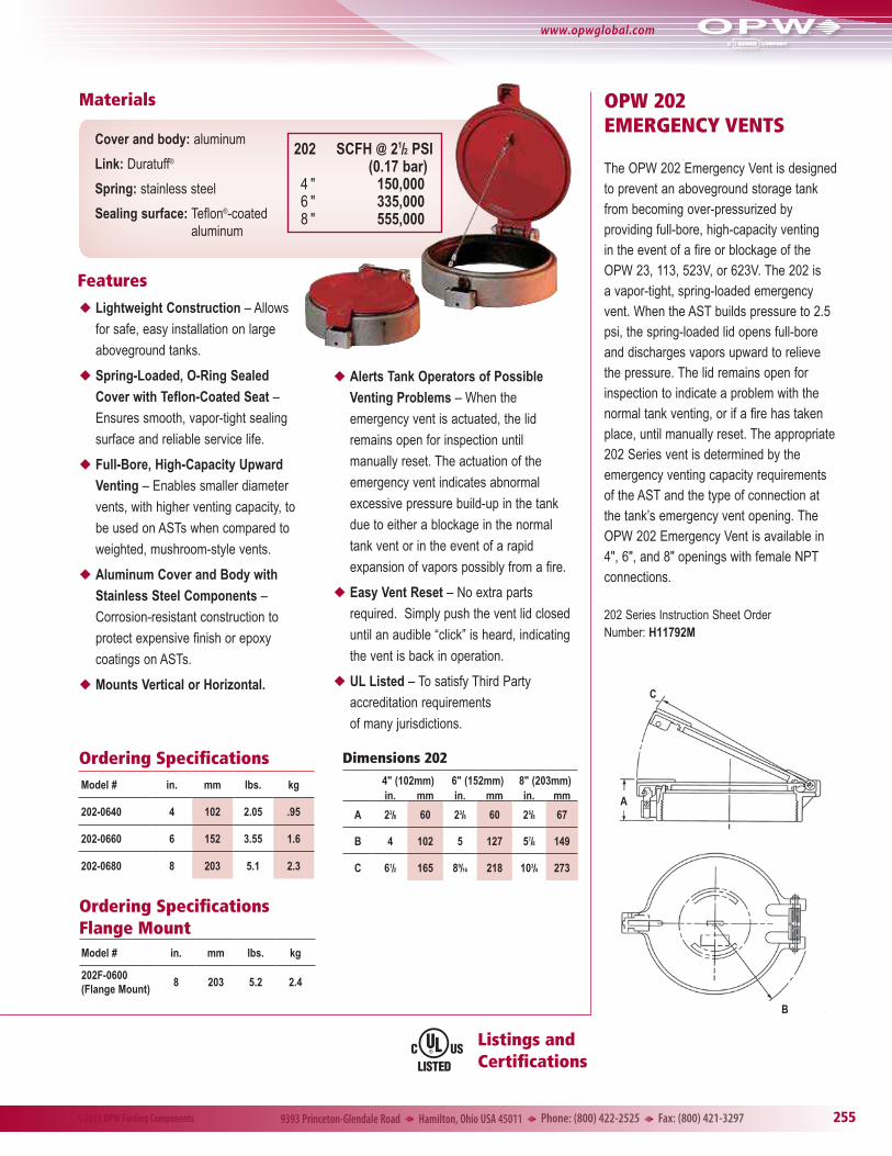
The OPW 202 Emergency Vent is designed to prevent an aboveground storage tank from becoming over-pressurized by providing full-bore, high-capacity venting in the event of a fire or blockage of the OPW 23, 113, 523V, or 623V. The 202 is a vapor-tight, spring-loaded emergency vent. When the AST builds pressure to 2.5 psi, the spring-loaded lid opens full-bore and discharges vapors upward to relieve the pressure. The lid remains open for inspection to indicate a problem with the normal tank venting, or if a fire has taken place, until manually reset. The appropriate 202 Series vent is determined by the emergency venting capacity requirements of the AST and the type of connection at the tank’s emergency vent opening. The OPW 202 Emergency Vent is available in 4", 6", and 8" openings with female NPT connections.
B
A
C
202 Series Instruction Sheet Order Number: H11792M
uLightweight Construction – Allows
for safe, easy installation on large
aboveground tanks.
uSpring-Loaded, O-Ring Sealed Cover with Teflon-Coated Seat –
Product # DescriptionIdentification Label Color lb. kg
623V-2203 2.5" to 6" WC Pres., -6" to -10" WC Vac. Thread-On Yellow 1.55 .70
623V-3203 2.5" to 6" WC Pres., -6" to -10" WC Vac. Thread-On Yellow 2.20 1.00
Conversion Table
Measurement Units
In H2O In Hg
= Oz. PSI (WC) (Merc) Bar
Bar x 236.0 14.5 401.4 29.53
In. Hg (Mercury) x 7.843 0.49 13.6 0.034
In H2O (WC) x 0.578 0.04 0.074 0.002
PSI x 16.00 27.68 2.04 0.069
Oz. x 0.063 1.73 0.128 0.004
u Pressure/Vacuum Setting – 2.5" to 6" water column pressure settings and -6" to -10" water column vacuum settings are factory preset and tested.
u Reliable Service – cycle tested to the equivalent of 80 years of service in the most severe environment without leakage problems.
u Corrosion-Resistant Construction – a Duratuff® composite body ensures a long service life.
u Easy Installation – the 623V is available in 2" and 3" threaded versions.
u Complies with NFPA 30 Requirements – for venting gasoline vapors upward.
u Manifold Vent Pipes – vent pipes may be manifolded to produce a single Pressure Vacuum Vent line. The 623V exceeds California’s requirements of a maximum vapor leak rate of 0.17 SCFH at 2.00 inches H2O.
u High Maximum Flow Rate – 6450 SCFH at 2 psi (0.1 bar) pressure drop.
u Leak Rate – multiple pressure vacuum vents may be installed on a single site. The 623V exceeds California standards with a leak rate of 0.05 SCFH or less at 2.00 inches H2O.
u Maintenance – no tools required. A removable snap fit top allows for easy maintenance (recommended yearly).
u 100-Mesh Stainless Steel Wire Screens – helps prevent debris and insects from entering the tank vent lines. An added screen installed at the base prevents debris from intruding from the vent stack.
u Adaptor Bushing – removable hex threaded bushing designed for easy installation on NPT threaded risers. Allows easy access to lower screen.
u Complies with NFPA 30 Requirements – for venting gasoline vapors upward.
u High Maximum Flow Rate – 7000 SCFH at 2 psi pressure drop.
u 40-Mesh Stainless Steel Wire Screen – helps prevent debris and insects from entering the tank vent lines.
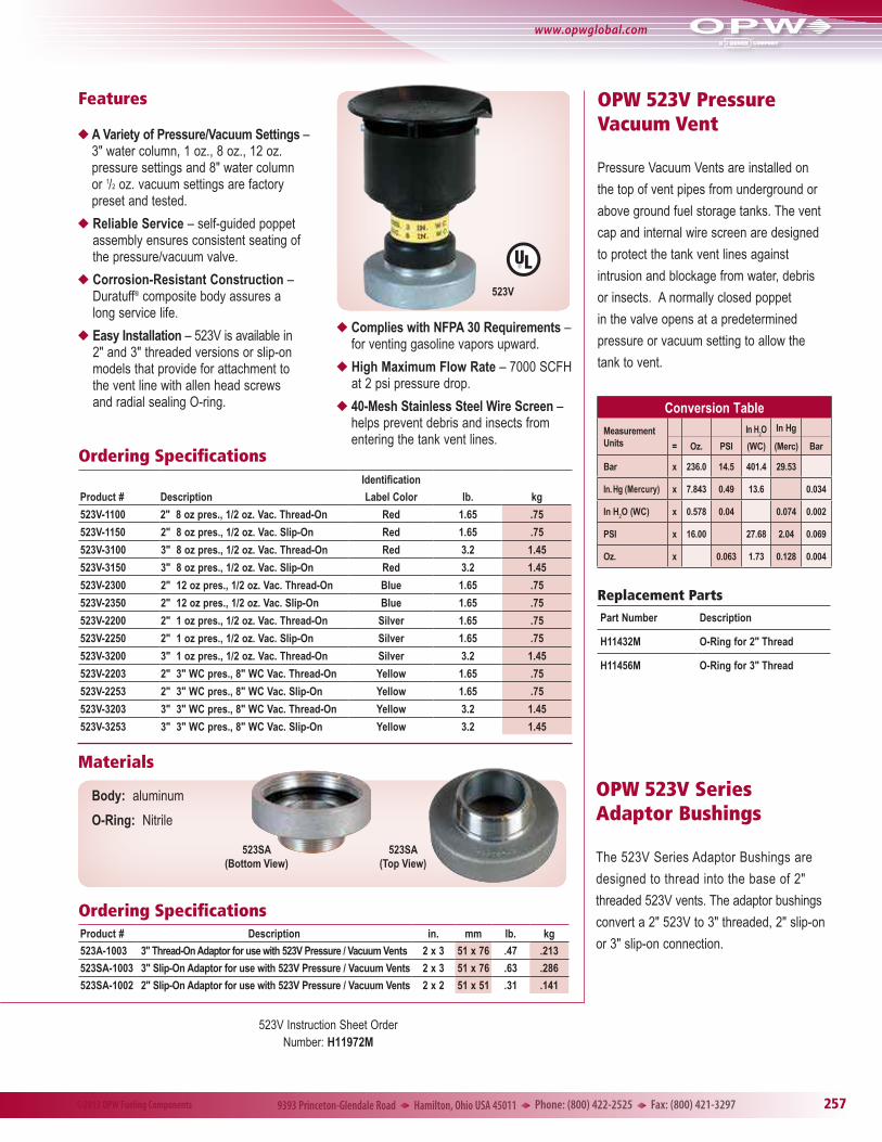
u A Variety of Pressure/Vacuum Settings – 3" water column, 1 oz., 8 oz., 12 oz. pressure settings and 8" water column or 1/2 oz. vacuum settings are factory preset and tested.
u Reliable Service – self-guided poppet assembly ensures consistent seating of the pressure/vacuum valve.
u Corrosion-Resistant Construction – Duratuff® composite body assures a long service life.
u Easy Installation – 523V is available in 2" and 3" threaded versions or slip-on models that provide for attachment to the vent line with allen head screws and radial sealing O-ring.
Materials
Body: aluminum
O-Ring: Nitrile
523SA(Bottom View)
523SA(Top View)
Ordering Specifications Product # Description in. mm lb. kg
523A-1003 3" Thread-On Adaptor for use with 523V Pressure / Vacuum Vents 2 x 3 51 x 76 .47 .213
523SA-1003 3" Slip-On Adaptor for use with 523V Pressure / Vacuum Vents 2 x 3 51 x 76 .63 .286
523SA-1002 2" Slip-On Adaptor for use with 523V Pressure / Vacuum Vents 2 x 2 51 x 51 .31 .141
OPW Utility Tank Vents are installed directly on the top of above ground storage tank or utility tank vent pipes. The vent cap is designed to protect the tank against intrusion of water, debris or insects. The 515ML incorporates a flame arrestor screen for jurisdictions that require these on tanks. A normally closed poppet in the valve opens at a predetermined pressure or vacuum setting to allow the tank to vent.
515ML
1
2
3
4
5B
11
109
8
DC
6
7B
7A
514F
A
B
12
3
C
D
E
46578
F
Dimensions (514F)in. mm
A 25/16 59
B 25/16 75
C 15/16 24
D 2 21/32 67
E 115/16 49
F 7/16 11
Dimensions (515ML)in. mm
A 25/16 59
B 51/4 133
C 31/8 79
D 115/16 49
Features
Materials
Features
Materials
u 3-Pound Pressure and 1 oz. Vacuum Settings – factory preset and tested to protect against product vapor loss and allow for rapid withdrawal of product from the tank.
u Reliable Service – precision-machined, lapped bronze pressure and vacuum seats ensure consistent seating of the pressure/vacuum valve.
u Corrosion-Resistant Construction – zinc/aluminum alloy body and zinc-plated steel dome assure a long service life.
u Easy Installation – 514F is available in 2" (111/2" NPSH) female straight threads with a Buna-N gasket.
u High Maximum Flow Rate – 3500 SCFH at 4.5 psi (0.31 bar) pressure drop.
u Lockable Base - a provision for padlocking the vent to the tank is integrated into the base.
Ordering SpecificationsProduct # in. mm lbs. kg
514F-3050 2 51 .46 .21
Replacement PartsKey Part # Description
1 H01967M Nut
2 H10096M Pressure Spring
3 H07355M Screen
4 H11432M Seal
5 C03991M Dome
6 H07356B Vacuum Disc
7 H08380AH Pressure Disc
8 H07353M Vacuum Spring
Ordering SpecificationsProduct # in. mm lbs. kg
515ML-1030 2 51 1.80 .82
Cap Body: High-tensile aluminum alloy construction. Has straight pipe threads with Nitrile gasket for tight seal to tank.
Dome: Plated steel
Screen: 40 mesh brass 515ML
514F
uFlame Arrestor Screen – for jurisdictions that require flame arrestors on tank vents.
u 5 PSI (0.34 bar) Pressure and 1 oz. Vacuum Settings – factory preset and tested to protect against product vapor loss and allow for rapid withdrawal of product from the tank.
u Reliable Service – precision-machined, lapped bronze pressure and vacuum seats ensure consistent seating of the pressure/vacuum valve.
uCorrosion-Resistant Construction – zinc/aluminum alloy body and zinc-plated steel dome assure a long service life.
u Easy Installation – 515ML is available in 2" (111/2" NPSH) male straight threads.
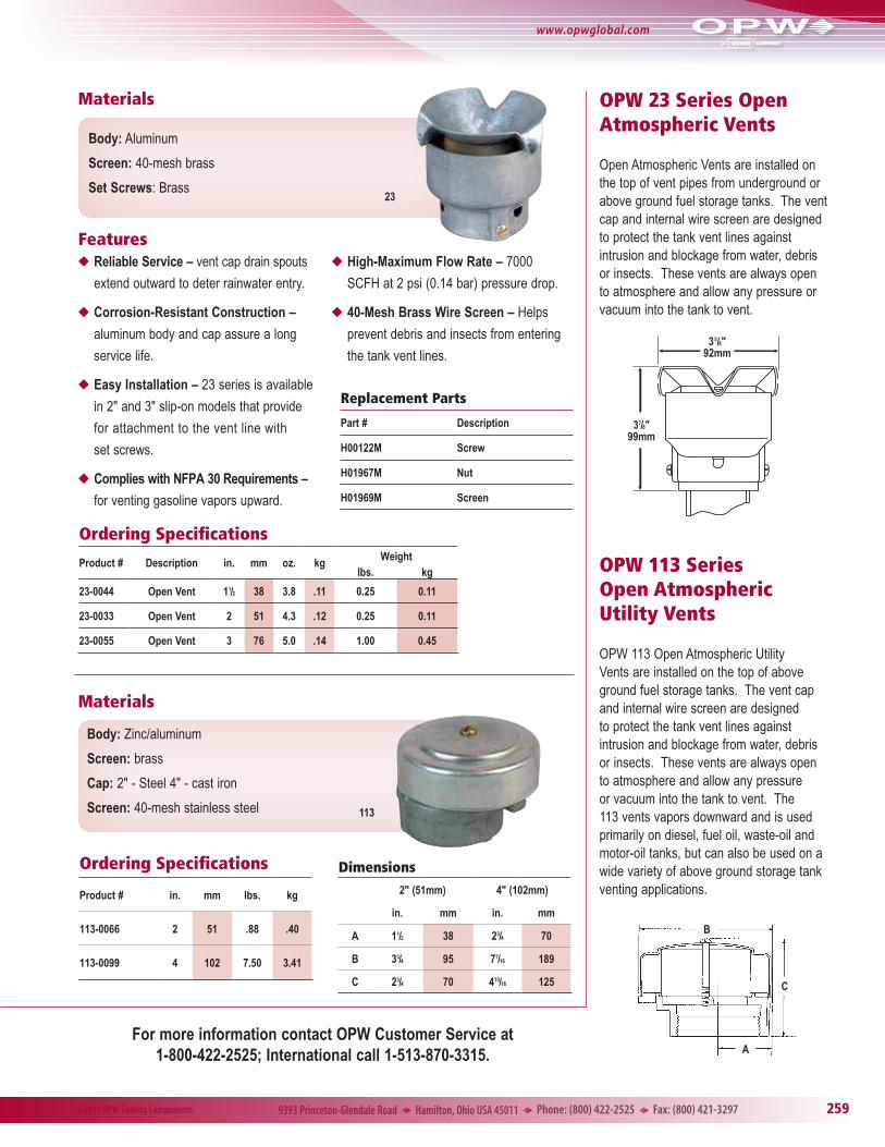
Open Atmospheric Vents are installed on the top of vent pipes from underground or above ground fuel storage tanks. The vent cap and internal wire screen are designed to protect the tank vent lines against intrusion and blockage from water, debris or insects. These vents are always open to atmosphere and allow any pressure or vacuum into the tank to vent.
OPW 113 Series Open Atmospheric Utility Vents
OPW 113 Open Atmospheric Utility Vents are installed on the top of above ground fuel storage tanks. The vent cap and internal wire screen are designed to protect the tank vent lines against intrusion and blockage from water, debris or insects. These vents are always open to atmosphere and allow any pressure or vacuum into the tank to vent. The 113 vents vapors downward and is used primarily on diesel, fuel oil, waste-oil and motor-oil tanks, but can also be used on a wide variety of above ground storage tank venting applications.
Materials
Features
Materials
23
Body: Aluminum
Screen: 40-mesh brass
Set Screws: Brass
uReliable Service – vent cap drain spouts
extend outward to deter rainwater entry.
uCorrosion-Resistant Construction –
aluminum body and cap assure a long
service life.
uEasy Installation – 23 series is available
in 2" and 3" slip-on models that provide
for attachment to the vent line with
set screws.
uComplies with NFPA 30 Requirements –
for venting gasoline vapors upward.
uHigh-Maximum Flow Rate – 7000
SCFH at 2 psi (0.14 bar) pressure drop.
u40-Mesh Brass Wire Screen – Helps
prevent debris and insects from entering
the tank vent lines.
Ordering Specifications
Product # Description in. mm oz. kg Weightlbs. kg
23-0044 Open Vent 11/2 38 3.8 .11 0.25 0.11
23-0033 Open Vent 2 51 4.3 .12 0.25 0.11
23-0055 Open Vent 3 76 5.0 .14 1.00 0.45
Replacement Parts
Part # Description
H00122M Screw
H01967M Nut
H01969M Screen
Ordering Specifications
Product # in. mm lbs. kg
113-0066 2 51 .88 .40
113-0099 4 102 7.50 3.41
Dimensions
2" (51mm) 4" (102mm)
in. mm in. mm
A 11/2 38 23/4 70
B 33/4 95 77/16 189
C 23/4 70 415/16 125
Body: Zinc/aluminum
Screen: brass
Cap: 2" - Steel 4" - cast iron
Screen: 40-mesh stainless steel 113
For more information contact OPW Customer Service at 1-800-422-2525; International call 1-513-870-3315.
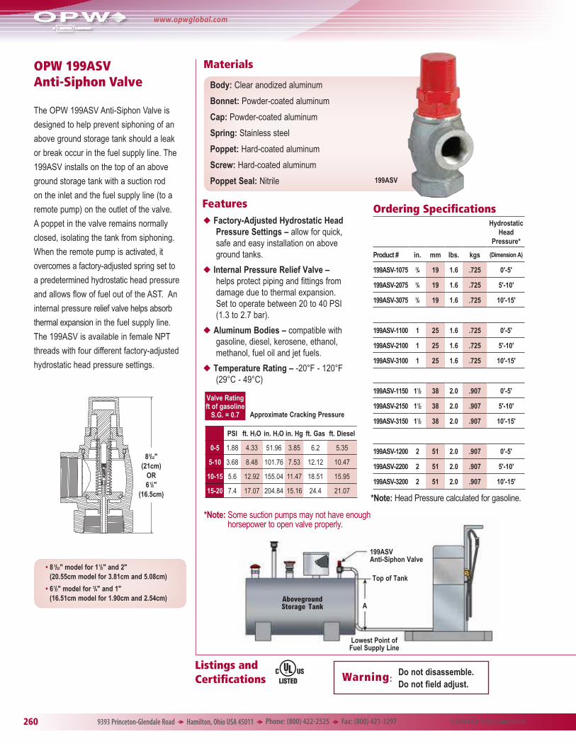
�•���8 3/32" model for 11/2" and 2" (20.55cm model for 3.81cm and 5.08cm)
�•��61/2" model for 3/4" and 1" (16.51cm model for 1.90cm and 2.54cm)
Listings and Certifications Warning:
Do not disassemble. Do not field adjust.
Features
Materials
Aboveground Storage Tank
199ASV Anti-Siphon Valve
Top of Tank
A
Lowest Point of Fuel Supply Line
199ASV
Body: Clear anodized aluminum
Bonnet: Powder-coated aluminum
Cap: Powder-coated aluminum
Spring: Stainless steel
Poppet: Hard-coated aluminum
Screw: Hard-coated aluminum
Poppet Seal: Nitrile
Ordering SpecificationsHydrostatic
Head Pressure*
Product # in. mm lbs. kgs (Dimension A)
199ASV-1075 3/4 19 1.6 .725 0'-5'
199ASV-2075 3/4 19 1.6 .725 5'-10'
199ASV-3075 3/4 19 1.6 .725 10'-15'
199ASV-1100 1 25 1.6 .725 0'-5'
199ASV-2100 1 25 1.6 .725 5'-10'
199ASV-3100 1 25 1.6 .725 10'-15'
199ASV-1150 11/2 38 2.0 .907 0'-5'
199ASV-2150 11/2 38 2.0 .907 5'-10'
199ASV-3150 11/2 38 2.0 .907 10'-15'
199ASV-1200 2 51 2.0 .907 0'-5'
199ASV-2200 2 51 2.0 .907 5'-10'
199ASV-3200 2 51 2.0 .907 10'-15'
PSI ft. H2O in. H2O in. Hg ft. Gas ft. Diesel
0-5 1.88 4.33 51.96 3.85 6.2 5.35
5-10 3.68 8.48 101.76 7.53 12.12 10.47
10-15 5.6 12.92 155.04 11.47 18.51 15.95
15-20 7.4 17.07 204.84 15.16 24.4 21.07
uFactory-Adjusted Hydrostatic Head Pressure Settings – allow for quick, safe and easy installation on above ground tanks.
uInternal Pressure Relief Valve – helps protect piping and fittings from damage due to thermal expansion. Set to operate between 20 to 40 PSI (1.3 to 2.7 bar).
uAluminum Bodies – compatible with gasoline, diesel, kerosene, ethanol, methanol, fuel oil and jet fuels.
uTemperature Rating – -20°F - 120°F (29°C - 49°C)
Valve Ratingft of gasoline
S.G. = 0.7
*Note: Head Pressure calculated for gasoline.
Approximate Cracking Pressure
*Note: Some suction pumps may not have enough horsepower to open valve properly.
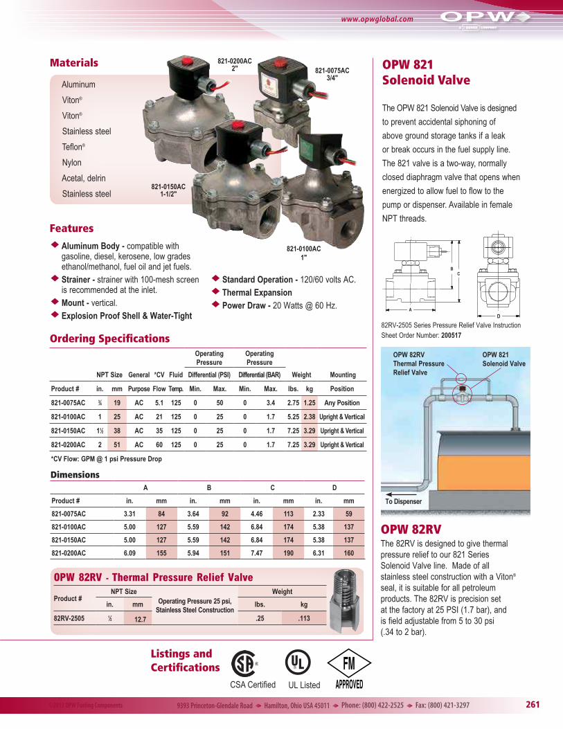
OPW 82RVThe 82RV is designed to give thermal pressure relief to our 821 Series Solenoid Valve line. Made of all stainless steel construction with a Viton® seal, it is suitable for all petroleum products. The 82RV is precision set at the factory at 25 PSI (1.7 bar), and is field adjustable from 5 to 30 psi (.34 to 2 bar).
Features
Materials
u Aluminum Body - compatible withgasoline, diesel, kerosene, low gradesethanol/methanol, fuel oil and jet fuels.
u Strainer - strainer with 100-mesh screenis recommended at the inlet.
u Mount - vertical.u Explosion Proof Shell & Water-Tight
u Standard Operation - 120/60 volts AC.u Thermal Expansionu Power Draw - 20 Watts @ 60 Hz.
Aluminum
Viton®
Viton®
Stainless steel
Teflon®
Nylon
Acetal, delrin
Stainless steel
DimensionsA B C D
Product # in. mm in. mm in. mm in. mm
821-0075AC 3.31 84 3.64 92 4.46 113 2.33 59
821-0100AC 5.00 127 5.59 142 6.84 174 5.38 137
821-0150AC 5.00 127 5.59 142 6.84 174 5.38 137
821-0200AC 6.09 155 5.94 151 7.47 190 6.31 160
821-0200AC2"
821-0100AC 1"
821-0075AC3/4"
821-0150AC1-1/2"
OPW 82RV - Thermal Pressure Relief Valve
Product #NPT Size
Operating Pressure 25 psi, Stainless Steel Construction
Weight
in. mm lbs. kg
82RV-2505 1⁄2 12.7 .25 .113
82RV-2505 Series Pressure Relief Valve Instruction Sheet Order Number: 200517
OPW Ball Valves are used throughout fueling systems where a shut-off point is desirable to isolate a section of the piping system. These full-port, forged brass valves feature a manual open-close arm and a quick quarter-turn handle, allowing easy shut down of your AST or UST system. Compatible with gasoline, alcohol fuels, diesel and MTBE. Available with Lockable Handle (LH).
Listings and Certifications
Featuresu Pressure rated to 600 psig (41 bar) WOG
u Blowout-proof stem
u Chrome-plated brass ball
u Secondary O-ring stem seal
u PTFE seats, thrust bearing and stem packing
D
B
A
C
Ordering Specifications and DimensionsDimensions (in.)
Model # Size (in.) A B C D
21BV-0050 1/2 0.59 2.28 1.81 3.35
21BV-0075 3/4 0.78 2.51 2.36 4.29
21BV-0100 1 0.98 2.97 2.52 4.29
21BV-0150 11/2 1.57 3.87 2.72 5.63
21BV-0200 2 1.96 4.29 3.03 5.63
21BV-0200SS 2 1.96 4.80 3.66 7.09
21BV-0300 3 3.15 6.10 5.12 8.35
*SS denotes Stainless Steel.
202233 Lockable Handle Kit for 1/2" Model (Handles sold separately)
202234 Lockable Handle Kit for 3/4" and 1" Models (Handles sold separately)
202235 Lockable Handle Kit for 1-1/2" and 2" Models (Handles sold separately)