86
Oracle® Reference Architecture SOA Infrastructure Release 3.2 E14479-03 February 2012

Oracle® Reference ArchitectureSOA Infrastructure
Release 3.2
E14479-03
February 2012

ORA SOA Infrastructure, Release 3.2
E14479-03
Copyright © 2009, 2010, Oracle and/or its affiliates. All rights reserved.
Primary Author: Stephen G. Bennett, Anbu Krishnaswamy
Contributing Author: Dave Chappelle, Bob Hensle, Mark Wilkins, Jeff McDaniel, Cliff Booth
Contributor: Sazi Temel, Martin Cookson
Warranty Disclaimer
THIS DOCUMENT AND ALL INFORMATION PROVIDED HEREIN (THE "INFORMATION") IS PROVIDED ON AN "AS IS" BASIS AND FOR GENERAL INFORMATION PURPOSES ONLY. ORACLE EXPRESSLY DISCLAIMS ALL WARRANTIES OF ANY KIND, WHETHER EXPRESS OR IMPLIED, INCLUDING, BUT NOT LIMITED TO, THE IMPLIED WARRANTIES OF MERCHANTABILITY, FITNESS FOR A PARTICULAR PURPOSE AND NON-INFRINGEMENT. ORACLE MAKES NO WARRANTY THAT THE INFORMATION IS ERROR-FREE, ACCURATE OR RELIABLE. ORACLE RESERVES THE RIGHT TO MAKE CHANGES OR UPDATES AT ANY TIME WITHOUT NOTICE.
As individual requirements are dependent upon a number of factors and may vary significantly, you should perform your own tests and evaluations when making technology infrastructure decisions. This document is not part of your license agreement nor can it be incorporated into any contractual agreement with Oracle Corporation or its affiliates. If you find any errors, please report them to us in writing.
Third Party Content, Products, and Services Disclaimer
This document may provide information on content, products, and services from third parties. Oracle is not responsible for and expressly disclaim all warranties of any kind with respect to third-party content, products, and services. Oracle will not be responsible for any loss, costs, or damages incurred due to your access to or use of third-party content, products, or services.
Limitation of Liability
IN NO EVENT SHALL ORACLE BE LIABLE FOR ANY DIRECT, INDIRECT, INCIDENTAL, SPECIAL OR CONSEQUENTIAL DAMAGES, OR DAMAGES FOR LOSS OF PROFITS, REVENUE, DATA OR USE, INCURRED BY YOU OR ANY THIRD PARTY, WHETHER IN AN ACTION IN CONTRACT OR TORT, ARISING FROM YOUR ACCESS TO, OR USE OF, THIS DOCUMENT OR THE INFORMATION.
Oracle is a registered trademark of Oracle Corporation and/or its affiliates. Other names may be trademarks of their respective owners.

iii
Contents
Send Us Your Comments ....................................................................................................................... vii
Preface ................................................................................................................................................................. ix
Document Purpose...................................................................................................................................... ixAudience....................................................................................................................................................... xDocument Structure .................................................................................................................................... xHow to Use This Document....................................................................................................................... xRelated Documents ..................................................................................................................................... xConventions ................................................................................................................................................ xii
1 Introduction to SOA Infrastructure
1.1 SOA Infrastructure is Different................................................................................................. 1-11.2 SOA Infrastructure Principles ................................................................................................... 1-2
2 SOA Infrastructure Logical View
2.1 Logical Architecture ................................................................................................................... 2-12.1.1 Service Consumers ............................................................................................................. 2-22.1.1.1 Composite Applications .............................................................................................. 2-32.1.2 Service Layers....................................................................................................................... 2-32.1.2.1 Utility Services .............................................................................................................. 2-42.1.2.2 Connectivity Services................................................................................................... 2-42.1.2.3 Data Services ................................................................................................................. 2-52.1.2.4 Business Services .......................................................................................................... 2-62.1.2.4.1 Business Activity Services.................................................................................... 2-62.1.2.4.2 Business Process Services..................................................................................... 2-72.1.2.5 Presentation Services.................................................................................................... 2-72.1.2.6 Composite Services ...................................................................................................... 2-82.1.2.7 Encapsulation................................................................................................................ 2-82.1.3 Service Providers ................................................................................................................. 2-92.1.4 SOA Infrastructure ........................................................................................................... 2-102.1.4.1 Service Bus.................................................................................................................. 2-122.1.4.1.1 Transport Mediation .......................................................................................... 2-122.1.4.1.2 Message Mediation and Transformation........................................................ 2-132.1.4.1.3 Security Mediation ............................................................................................. 2-142.1.4.1.4 Routing................................................................................................................. 2-15

iv
2.1.4.1.5 Monitoring, Management and Security .......................................................... 2-152.1.4.2 Metadata Repository ................................................................................................. 2-152.1.4.3 Service Registry.......................................................................................................... 2-172.1.4.4 SOA Security .............................................................................................................. 2-192.1.4.5 Service Monitoring Framework............................................................................... 2-202.1.4.6 Service Management Framework ........................................................................... 2-21
3 SOA Infrastructure Product Mapping View
3.1 Oracle Product Mapping - SOA Infrastructure ...................................................................... 3-13.1.1 Oracle Service Bus (OSB) .................................................................................................... 3-33.1.2 Oracle Enterprise Repository (OER) ................................................................................. 3-43.1.3 Oracle Service Registry (OSR)............................................................................................ 3-53.1.4 Oracle Web Services Manager (OWSM)........................................................................... 3-53.1.5 Oracle Enterprise Manager for SOA (OEM) .................................................................... 3-63.2 Oracle Product Mapping - Service Platform........................................................................... 3-73.2.1 BPEL Process Manager (BPEL PM)................................................................................... 3-93.2.2 Oracle Business Process Management (OBPM) ........................................................... 3-103.2.3 Oracle Business to Business Integration (OB2B) .......................................................... 3-103.2.4 Oracle Business Rules (OBR)........................................................................................... 3-103.2.5 Oracle WebLogic Server (OWLS) ................................................................................... 3-103.2.6 Oracle Coherence (OCOH).............................................................................................. 3-113.2.7 Oracle Data Services Integrator (ODSI)......................................................................... 3-113.2.8 Oracle Data Integrator (ODI) .......................................................................................... 3-113.2.9 Oracle Complex Event Processing (OCEP)................................................................... 3-113.2.10 Oracle Integration Adapters (OIA) ................................................................................ 3-123.2.11 Oracle WebCenter (OWC) ............................................................................................... 3-123.2.11.1 Oracle WebCenter Portal ......................................................................................... 3-123.2.11.2 Oracle Webcenter Content ....................................................................................... 3-123.2.11.3 Oracle Webcenter Sites ............................................................................................. 3-123.2.11.4 Oracle WebCenter Social .......................................................................................... 3-13
4 SOA Infrastructure Deployment View
4.1 Deployment Models ................................................................................................................... 4-14.1.1 Segregated Deployment...................................................................................................... 4-14.1.2 Federated Deployment ....................................................................................................... 4-14.1.2.1 Federated Service Bus .................................................................................................. 4-34.1.2.1.1 Centralized Federation Topology ....................................................................... 4-34.1.2.1.2 Distributed Federation Topology ....................................................................... 4-44.1.2.1.3 Hybrid Federation Topology............................................................................... 4-54.1.2.1.4 Drivers for Federated Service Bus Configurations........................................... 4-64.1.2.2 Federated Registries ..................................................................................................... 4-64.1.3 Product Deployment Strategies......................................................................................... 4-74.1.3.1 SOA Infrastructure Topology ..................................................................................... 4-74.1.3.2 Oracle Service Bus (OSB) Deployment................................................................... 4-104.1.3.3 Oracle Enterprise Repository (OER) Deployment................................................ 4-104.1.3.4 Oracle Service Registry (OSR) Deployment .......................................................... 4-104.1.3.5 Oracle Web Services Manager (OWSM) Deployment ......................................... 4-11

v
4.2 SOA Infrastructure Best Practices.......................................................................................... 4-114.2.1 OSB Architecture Trade-offs ........................................................................................... 4-114.2.1.1 Bus Architecture ........................................................................................................ 4-114.2.1.2 Endpoint Deployment .............................................................................................. 4-114.2.1.3 Service Bus Appliance............................................................................................... 4-124.2.1.4 Message Bus ............................................................................................................... 4-124.2.2 Mediation versus Orchestration ..................................................................................... 4-124.2.3 OWSM Architecture Trade-offs...................................................................................... 4-13
5 SOA Infrastructure Process View
5.1 Runtime SOA Infrastructure Process ....................................................................................... 5-15.2 SOA Management Infrastructure Process ............................................................................... 5-2
6 SOA Infrastructure Development View
6.1 Design-time Process.................................................................................................................... 6-16.2 Oracle Fusion SOA Development Tools.................................................................................. 6-46.3 Packaging ..................................................................................................................................... 6-6
7 Summary
A Further Reading
A.1 Related Documents.................................................................................................................... A-1A.2 Other Resources ......................................................................................................................... A-1

vi
List of Figures
2–3 Service Consumers...................................................................................................................... 2-22–4 Service Layers .............................................................................................................................. 2-42–5 Encapsulation .............................................................................................................................. 2-92–6 Service Providers......................................................................................................................... 2-92–7 SOA Infrastructure................................................................................................................... 2-112–8 Service Bus Logical Relationships ......................................................................................... 2-122–9 Transport Mediation................................................................................................................ 2-132–10 Security Mediation................................................................................................................... 2-142–11 Metadata Repository Logical Relationships ........................................................................ 2-162–12 Metadata Repository ............................................................................................................... 2-172–13 Service Registry Entities.......................................................................................................... 2-182–14 Service Registry Logical Relationships ................................................................................. 2-182–15 Security Framework Logical Relationships ......................................................................... 2-202–16 Monitoring Framework Logical Relationships.................................................................... 2-212–17 Management Framework Logical Relationships................................................................. 2-223–1 SOA Infrastructure - Oracle Product Mapping ...................................................................... 3-23–2 Service Platform - Oracle Product Mapping........................................................................... 3-83–3 BPEL Process Manager............................................................................................................... 3-94–1 Segregated Deployment............................................................................................................. 4-14–2 SOA Domain Federation............................................................................................................ 4-34–3 Centralized Federation Topology............................................................................................. 4-44–4 Distributed Federation Topology ............................................................................................. 4-54–5 Hybrid Federation Topology .................................................................................................... 4-64–7 Oracle SOA Infrastructure Topology (Sample) ...................................................................... 4-84–8 Service Promotion....................................................................................................................... 4-94–9 SOA Infrastructure Physical Deployment Model .................................................................. 4-95–1 Runtime SOA Infrastructure ..................................................................................................... 5-16–1 Design-time Progression............................................................................................................ 6-26–2 Oracle Fusion SOA Development Tools.................................................................................. 6-56–3 Example High-level Packaging Diagram ................................................................................ 6-86–4 Example Service Packaging Detail Diagram........................................................................... 6-8

vii
Send Us Your Comments
ORA SOA Infrastructure, Release 3.2
E14479-03
Oracle welcomes your comments and suggestions on the quality and usefulness of this publication. Your input is an important part of the information used for revision.
■ Did you find any errors?
■ Is the information clearly presented?
■ Do you need more information? If so, where?
■ Are the examples correct? Do you need more examples?
■ What features did you like most about this document?
If you find any errors or have any other suggestions for improvement, please indicate the title and part number of the documentation and the chapter, section, and page number (if available). You can send comments to us at [email protected].

viii

ix
Preface
Service Oriented Architecture is an IT strategy which spans the entire enterprise. IT projects are implemented to fit within an SOA and are therefore just a piece of the larger SOA initiative. SOA Infrastructure projects differ slightly from the typical SOA project delivery in that the focus is mostly on enabling infrastructure products, rather than developing new business function or providing for other business driven needs. The focus of SOA Infrastructure is to enable the delivery teams to deliver SOA projects faster, as well as make the overall SOA undertaking much more manageable. There are two drivers for realizing SOA Infrastructure, as this technology plays a role in both design time and runtime activities.
The EA teams are responsible for establishing the high-level enterprise SOA reference architecture and planning the procedures and guidelines that need to be followed when developing applications and services that will be considered participants of the SOA. These planning and strategizing activities place demands on SOA Infrastructure to make these aspects of SOA possible without having to develop infrastructure in house. Design time demands include application and service composition, service orchestration, loose coupling, controlled service discovery, service versioning, managing security policies, and data format conversions.
From the runtime side of things, it is crucial for SOA success that the operations team fully control and maintain the operational environment as the SOA matures over time. These teams need infrastructure to assist with monitoring and managing the SOA environment.
These demands surface from the concepts brought to bear by the adoption of SOA and the generally accepted practices of how an enterprise goes about adopting SOA. Common infrastructure products, which are categorized as SOA Infrastructure, include service bus, service repository and registry, service management, and service oriented security products are utilized to make SOA possible.
Document PurposeThis document enumerates the key capabilities required for SOA implementations and organizes them into logical architectural components. Oracle Fusion Middleware products are mapped to the logical architecture and various views of the SOA Infrastructure including physical, deployment, process, and development views are elaborated in detail. This document provides an understanding of the best way to implement an effective SOA infrastructure.

x
AudienceThis document is primarily intended for Infrastructure Architects responsible for building SOA infrastructure. Enterprise Architects and Project Architects that want to understand the best way to build applications, processes, and Services will gather valuable insight from a good understanding of the capabilities of the SOA infrastructure. Developers will also gain sufficient understanding of the various SOA development infrastructure components required to build Services and composite applications.
Document StructureThis document is organized into the following sections.
Chapter 1 - gives an introduction to SOA infrastructure.
Chapter 2 - defines the logical architecture and maps the capabilities to the core logical components.
Chapter 3 - defines the product mapping view of the SOA infrastructure which describes and maps the Oracle Fusion Middleware products to the logical architecture.
Chapter 4 - describes the deployment view of the SOA infrastructure.
Chapter 5 - explains the process view and describes the runtime infrastructure process and SOA management process in detail.
Chapter 6 - covers the development view of the SOA infrastructure and goes over the design time process and design time tools.
Chapter 7 - provides a summary of the SOA Infrastructure document.
Appendix A - provides a list of documents and URLs for further reading.
How to Use This DocumentThis document should be read by everyone that is interested in learning about architecting and building an enterprise class SOAInfrastructure. It is one of the documents in the collection that comprise Oracle Reference Architecture.
This document can be read from beginning to end or as a reference. If specific infrastructure components are not applicable at this point in time, you can skip that part but be sure to read the interdependencies of the technologies/products to ensure that there are no holes in the architecture.
Related DocumentsIT Strategies from Oracle (ITSO) is a series of documentation and supporting collateral designed to enable organizations to develop an architecture-centric approach to enterprise-class IT initiatives. ITSO presents successful technology strategies and solution designs by defining universally adopted architecture concepts, principles, guidelines, standards, and patterns.

xi
ITSO is made up of three primary elements:
■ Oracle Reference Architecture (ORA) defines a detailed and consistent architecture for developing and integrating solutions based on Oracle technologies. The reference architecture offers architecture principles and guidance based on recommendations from technical experts across Oracle. It covers a broad spectrum of concerns pertaining to technology architecture, including middleware, database, hardware, processes, and services.
■ Enterprise Technology Strategies (ETS) offer valuable guidance on the adoption of horizontal technologies for the enterprise. They explain how to successfully execute on a strategy by addressing concerns pertaining to architecture, technology, engineering, strategy, and governance. An organization can use this material to measure their maturity, develop their strategy, and achieve greater levels of success and adoption. In addition, each ETS extends the Oracle Reference Architecture by adding the unique capabilities and components provided by that particular technology. It offers a horizontal technology-based perspective of ORA.
■ Enterprise Solution Designs (ESD) are industry specific solution perspectives based on ORA. They define the high level business processes and functions, and the software capabilities in an underlying technology infrastructure that are required to build enterprise-wide industry solutions. ESDs also map the relevant application and technology products against solutions to illustrate how capabilities in Oracle’s complete integrated stack can best meet the business, technical, and quality of service requirements within a particular industry.
ORA SOA Infrastructure, along with ORA SOA Foundation, extend the Oracle Reference Architecture. They are part of a series of documents that comprise the SOA Enterprise Technology Strategy which is included in the IT Strategies from Oracle collection.
Please consult the ITSO web site for a complete listing of SOA and ORA documents as well as other materials in the ITSO series.
Suggested Pre-readingThe following documents are suggested pre-reading for those that would like to more fully understand the concepts this document builds upon.
The Software Engineering in an SOA Environment document lays out the process and techniques needed to develop enterprise class SOA Services. It provides an approach
xii
to augment the traditional solution delivery methods with the changes and additions required for SOA Service development and management.
The ORA SOA Foundation document describes the concepts of SOA and defines the Service Layers and SOA Infrastructure layers that are referred in this document.
ConventionsThe following typeface conventions are used in this document:
In addition, the following conventions are used throughout the SOA documentation:
"Service" v. "service" - In order to distinguish the "Service" of Service Oriented Architecture, referred to throughout the SOA ETS document series, the word appears with its initial letter capitalized ("Service"), while all other uses of the word appear in all lower-case (e.g. "telephone service"); exceptions to this rule arise only when the word "service" is part of a name, such as, "Java Message Service" ("JMS"), "Web Service", etc.
Convention Meaning
boldface text Boldface type in text indicates a term defined in the text, the ORA Master Glossary, or in both locations.
italic text Italics type in text indicates the name of a document or external reference.
underline text Underline text indicates a hypertext link.

1
Introduction to SOA Infrastructure 1-1
1Introduction to SOA Infrastructure
Infrastructure as it relates to a Service-Oriented Architecture (SOA) is the basic technologies and building blocks necessary to make a SOA work effectively in an enterprise. SOA is much larger than applying technology and has organizational and procedural aspects as well. This document will focus on the physical tools and technologies that implement the SOA Infrastructure.
1.1 SOA Infrastructure is DifferentThe key difference between SOA Infrastructure and other types of infrastructure is summarized below:
■ SOA Infrastructure is based on standards allowing you to choose from various products and vendors which are best suited to meet your requirements, yet still interoperate with other service based technology which you may have previously adopted.
■ The highly distributed, heterogeneous nature of SOA attempts to bring a number of disparate moving parts together, making it very complex naturally. This very characteristic of SOA infrastructure calls for due diligence and careful planning when designing and building the SOA infrastructure.
■ Services are more granular than applications. So the infrastructure should be able to support the distribution, deployment, discovery, and management of these granular artifacts as opposed to the monolithic applications which are much easier to deploy and manage.
■ Typically, application infrastructure provides the initial foundation for deploying applications but beyond that point only upgrades to the infrastructure and applications would be needed. In contrast, SOA Infrastructure is offered in multiple independent products that can be deployed in different order based on the specific requirements and strategy of the enterprise. This allows the purchase of infrastructure needed to continue the path of maturing SOA independently.
The concepts of Service-Oriented Architecture have been around for some time now; however, until recently, there has been little standards-based infrastructure technology to enable SOA and make it realistic to achieve. The pathway to SOA Infrastructure that has emerged today is a logical evolution built on past infrastructure and largely based on standards.
Some of the major challenges that arise with SOA without the assistance of a SOA infrastructure include:
■ Avoiding tightly coupled Service connectivity which results in a rigid and inflexible architecture.

SOA Infrastructure Principles
1-2 ORA SOA Infrastructure
■ Achieving a consistent data format and representation of enterprise data entities.
■ Understanding which Services are available, where they reside, their contract, invocation protocols, and rules for use.
■ Monitoring and enforcing quality of service such as service level agreements described by Service contracts.
■ Managing Service versioning and Service life cycle requirements.
■ Establishing the centralized management of security policies for SOA participants.
■ Achieving flexibility where coarse grained Services and applications can be composed of existing Services.
■ Invoking Services over heterogeneous transports using varying message brokering capabilities.
■ Achieving the performance and SLA requirements in a highly distributed and heterogeneous environment.
1.2 SOA Infrastructure PrinciplesThis section defines some of the principles of SOA infrastructure. These principles provide the guidance for creating a sound SOA infrastructure.
■ Standards Support
■ The SOA Infrastructure must be based on open standards. This supports a best of breed approach and prevents vendor lock in.
■ SOA Infrastructure must support all Services with standards-based interfaces, regardless of their choice of implementation technology.
■ Choice of Service hardware, operating system, or implementation language should not constrain choices for Service consumer.
■ The SOA infrastructure must support reliable messaging (e.g. WS Reliable Messaging, JMS, etc.)
■ Data Management
■ The exchange of data between internal and external systems must be logged and time-stamped to the extent necessary to maintain consistent documentation and transaction trace of this communication. The SOA Infrastructure will provide communication logging and audit trail capabilities, but logging on business level must be maintained by each Service implementation.
■ Data replication must be avoided. If an application demands a local representation of data in order to operate, control on the integrity of the replicated data is the assumed responsibility of the demanding application and not the responsibility of the SOA Infrastructure.
■ Infrastructure Capabilities
■ The SOA Infrastructure must provide the capabilities to deploy, publish, discover, invoke, monitor, and manage Services.
■ Services must utilize the connection management and recovery functions provided by the SOA Infrastructure.
■ The scaling of the SOA Infrastructure must be based on the requirements from the business. The technical infrastructure must be scalable to support the

SOA Infrastructure Principles
Introduction to SOA Infrastructure 1-3
requirements on involved parties regarding performance, response time, availability, network connections, and capacity.
■ SOA Infrastructure must support multiple versions of the Service concurrently and have ability to introduce new versions of the Service without requiring all the consumers to change simultaneously.
■ SOA Infrastructure must provide location transparency capabilities to decouple consumers from providers.
■ All integration between disparate business components must take place through the middleware provided as part of the SOA Infrastructure.

SOA Infrastructure Principles
1-4 ORA SOA Infrastructure

2
SOA Infrastructure Logical View 2-1
2SOA Infrastructure Logical View
It is important to decide on the role of each infrastructure component, and the technologies to embrace, before selecting products. These decisions are best captured as part of a reference architecture that can then be shared with architects and development teams across the organization. Refer to Figure 2–1 on material that can be included in a reference architecture and how a concrete architecture can realize the reference architecture.
Figure 2–1 Reference Architecture in context
The intent is to establish a consistent approach that helps promote interoperability and reuse. This chapter explores the logical architecture of SOA Infrastructure.
2.1 Logical ArchitectureFigure 2–2 is the logical architecture that supports the capabilities described in the ORA SOA Foundation document. This section details each layer of the logical

Logical Architecture
2-2 ORA SOA Infrastructure
architecture describing its roles and the interactions with the other layers and components.
Figure 2–2 Logical Architecture
2.1.1 Service Consumers Service consumers are, of course, consumers of Services, but more importantly, they do not offer any SOA capabilities nor are they required to conform to SOA principles (assuming they are not also Service providers). As highlighted in Figure 2–3 Service consumers may be end-users, composite applications, or other systems in purely system-to-system interactions.
Figure 2–3 Service Consumers

Logical Architecture
SOA Infrastructure Logical View 2-3
2.1.1.1 Composite ApplicationsComposite Applications is a term used to define applications built primarily of Services. These Services may belong to any of the Service layers previously described. The applications may dictate the need for Services, identifying business needs that can be developed in the form of Services. This is often referred to as top-down Service identification. In essence, the application is defined first, and the Services used to compose the application are identified and constructed. Composite applications may evolve and expand over time as additional Services are created. This supports incremental business value through the iterative development of new Services, reducing the risk associated with applications by delivering functionality in smaller, more consistent increments.
As the portfolio of Services increases, the ability to rapidly compose new applications increases. The ratio of Services that already exist versus Services that need to be built changes over time. Eventually, composite applications may be composed almost entirely of existing Services. At this point it is conceivable that applications can be built without any development effort at all.
Common examples of Composite Applications include portals and BPM processes. Portals may be composed of Presentation Services, while BPM processes may be composed of Business, Data, and Connectivity Services. Technologies are evolving in this area to allow these types of applications to be configured rather than developed. This will allow more to be done by business analysts and end users further reducing development efforts required to meet application needs and speed time to market.
Composite Applications consume Services, they are not service providers since no services are exposed and therefore, they cannot be classified as a Service themselves; however, they may have "Servicable" functionality, but this is deployed separately. As Service consumers, Composite Applications are positioned at the top of the diagram in Figure 2–3.
The BPM Process contained in Composite Applications in Figure 2–3 refers to any type of process that is a Service consumer, but not a Service provider; other processes exposed as Services would all be classified in the Business Process Service layer.
Service enabled applications that are only Service consumers are referred to as "client applications". Client applications differ from composite applications in that they are not originally designed for SOA. Typically client applications consume Services merely for the benefit of the integration capabilities of available Services. On the maturity scale client applications are 'opportunistic' at best. Client applications represent the cases where traditional applications happen to invoke Services
2.1.2 Service LayersIn order for Services to be versatile and support reuse, there must be a clear separation of concerns in terms of what they do from how they are used. The objective of this section is to describe architectural principles that enforce this separation of concerns to help maximize versatility and reuse.
Services should be written to accomplish their function regardless of what protocol is used to invoke them, where they physically exist, or on what type of hardware or operating system they run. This provides for maximum reuse by allowing access through multiple types of interfaces. It also provides greater versatility in how they are deployed and what underlying technologies are used.
Architectural Principles
1. A Service must not have any dependency on the identity of the consumer that invokes it.

Logical Architecture
2-4 ORA SOA Infrastructure
2. Services must not be tied to any particular underlying technology, delivery channel, or physical location.
The logical architecture defines six logical categories of Services: Presentation, Business Process, Business Activity, Data, Connectivity, and Utility Services (See Figure 2–4).
Figure 2–4 Service Layers
The rest of this section discusses the capabilities of each Service type.
2.1.2.1 Utility ServicesUtility Services is a classification of Services that are not directly related to performing business operations. That is, any Service that is not providing the connectivity, data management, business, or presentation logic associated with a business activity. Utility Services generally perform infrastructure-related functions, such as security (credential mapping, access control, auditing), logging, notification, policy lookup, transaction watermarking, etc. This classification of IT functions is often referred to as "cross-cutting" and are, therefore, drawn perpendicular to the other services in this diagram. They also typically rely heavily on the SOA Infrastructure (see below) for their implementation.
Utility Services do not carry any business context or have an affinity to any specific application; they are often the simplest and most reused Services in a SOA environment.
Architectural Principles
1. Utility Services must not contain business logic
2.1.2.2 Connectivity ServicesConnectivity Services provide a means to bridge current application technologies with SOA. They establish connectivity with legacy applications that do not inherently provide service-oriented interfaces. Connectivity may be accomplished using a variety of means, such as messaging systems, application adapters, and custom code. Connectivity Services expose the functions of legacy systems as Services in an SOA environment. They provide standards based interfaces, such as SOAP, which are then

Logical Architecture
SOA Infrastructure Logical View 2-5
consumed by higher-level Services or client applications through Service Infrastructure.
Services exposed at this layer are not intended to reflect business context in any way. Being context-neutral, they can be used in many different business scenarios. Data obtained by these Services will usually map directly to data representations in the native legacy systems. Adding business context or data mapping will effectively promote them to a higher level (e.g. business or data Services).
Architectural Principles
1. Connectivity Services must be stateless.
2. Connectivity Services may translate the representation of data, e.g., to and from XML, but do not apply rules-based transformation or aggregate data from multiple sources.
3. Connectivity Services must not include business logic.
2.1.2.3 Data ServicesData Services are used to access data from various sources using many different technologies, and present data in a business-friendly form. Data may originate in various databases, flat files, XML files, and legacy systems. Data Services offer a way to aggregate, transform, and synchronize data from multiple sources. They expose data in a format that best supports business Services and composite business applications. This creates an abstraction between the users of data and the sources of data. Users of data do not need to be concerned with where data is stored, how it is stored, or how it is represented in its native form. They can work with representations (schemas) of greater business value, such as canonical data models.
Data Services may access data directly, or may use Connectivity Services to obtain data from legacy applications. Connectivity Services provide a means to interact with legacy systems through APIs rather than directly to the database. Though this may add processing overhead, it is often preferred when updates to data might affect applications that rely on the data.
Like Connectivity Services, Data Services do not include any business logic. This allows them to be reused in different business contexts without modification. They represent business objects, such as customer, employee, and order, with the associated logic for ensuring consistency of such constructs.
Modern development tools can improve the development of Data Services. They provide visual editing and mapping capabilities that allow aggregation and transformation Services to be configured without cumbersome low-level coding. They can also provide enhanced features, such as caching and redaction. Redaction is the ability to reduce the data returned by a Service according to the entitlements of the user invoking the Service. This permits the same Service to be used by different users in different roles without having to hard code change to results sets.
Architectural Principles
1. Data Services must be tied to an enterprise information model.
2. Data Services must not contain business logic.
3. Data Services must be stateless.
4. Business Services drive the need for Data Services.
5. Data is owned by the enterprise - accountability and stewardship must be delegated to the authoritative business source.

Logical Architecture
2-6 ORA SOA Infrastructure
6. Data Services should enforce the separation of data access from the use of data by other Services i.e. other Services should not perform their own data access.
2.1.2.4 Business ServicesThere are many similarities between Business Activity Services and Business Process Services, shown in the diagram in Figure 2–4, so this section describes the common characteristics first, followed by separate descriptions detailing their differences. The sometimes subtle reason for the separation of the two types of Business Services is that, while Business Activity Services focus on static business functions, Business Process Services provide dynamic workflow orchestrations of business functions.
Business Services are the most commonly talked about Services in a SOA. They expose business operations via Service interfaces to establish a single, rationalized way to perform business functions. Operations may be simple atomic business functions, such as obtaining a stock quote, or complex / long running, such as starting a workflow process or kicking off a batch process.
Business Services represent operations that either have a high likelihood of reuse or a significant value to the organization. Engineering and exposing these operations as Business Services promotes interoperability between systems and creates a discoverable, published, rationalized, and managed way of performing these functions. It also promotes agility if the Services are packaged and managed as separate deployable and executable units. Services can be modified far more quickly and easily as standalone modular units than operations embedded and intertwined in large, complex applications.
The reuse potential of Business Services is generally less than Data and Connectivity Services. As the level of complexity increases, the likelihood of reuse is reduced. For this reason Business Services offer more value as a way to rationalize IT operations and achieve agility than as a way to promote reuse. By abstracting the users of Services from the system interactions needed to perform those Services, they provide a way for IT to evolve its systems without a direct impact to the users.
Simple Services may be developed using ordinary low level development platforms, such as J2EE or .NET, while more complex Services might be created with workflow management tools. They may be stateless operations that involve a single atomic transaction, or stateful processes that interact with multiple applications and Services asynchronously.
Architectural Principles
1. All transactional processing required by a Business Service must be self-contained within the Service. Transactions cannot span Service boundaries.
2. Business Services should be individually packaged and deployed.
3. Business Services are presentation-neutral, e.g., do not include formatting and presentation metadata.
4. Business logic must be separated from underlying technology and delivery channels.
2.1.2.4.1 Business Activity Services Business Activity Services are typically identified through a top-down method of functional decomposition, they are units of business logic offered as Services. The business logic may be simple operations, such as calculating sales tax, or more complex operations, such as transferring money electronically in a banking system.

Logical Architecture
SOA Infrastructure Logical View 2-7
This category of Services may also include business rules functionality (Services offering business rules are often called Decision Services).
Architectural Principles
1. Business Activity Services must be stateless.
2. Business Activity Services should be designed to be idempotent (i.e. perform their action once regardless of the number of times called; this avoids duplication when an action is retried for any reason).
2.1.2.4.2 Business Process Services Business Process Services are typically identified through a top-down method of process decomposition and represent shared business processes. They can be complete business processes or independently defined subprocesses. For example, the process for fulfilling a product order may differ slightly depending on the manner in which it was ordered. The common portion of all order processes may be defined once and reused by other higher-level processes that are unique to the method of ordering. This level of reuse is most valuable for establishing consistency for doing business. Exposed as Services, these subprocesses can be easily incorporated into higher-level processes while being managed by Service Infrastructure.
Business Process Services are units of business logic just like Business Activity Services, but the logic is likely to represent more complex operations such as orchestrating the interaction with multiple systems to handle a customer service enquiry.
The, potentially complex, process orchestrations of Business Process Services are likely to involve business rules to support process branching and compensating transactions to support fault handling in business processes.
Architectural Principles
1. Business Services should have an "undo" method to correspond with each "execute" method (see "compensating transactions" below).
Compensating Transactions: unlike simple database "undos", long running business processes cannot be simply undone. In cases where a series of activities are preformed in the execution of a long running business process, the reversal of the process (in the event of error condition, or a processing exception for higher-level business reason) may not be as simple as undoing the individual activities that make-up the process. An example of a situation requiring a compensating transaction might be a process committing resources in anticipation of user input; if the input is not received within a predetermined time the process fails, however, the resource cannot be simply replaced and some form of compensating action must be performed.
2.1.2.5 Presentation ServicesAs in most application architectures, the highest layer involves interaction with clients. If a client happens to be an end user, then the information provided by the system must be merged with metadata to describe how that information is formatted and presented. Since all Service layers discussed so far are presentation-neutral, the consumer of those Services must perform presentation-specific formatting before the information reaches the client.
In addition to formatting, a User Interface (UI) layer will often merge data from multiple unrelated sources in order to create the most beneficial experience. For example, if a user is browsing a parts catalog, the system may include a selection of tools for sale. The proper place to merge this data is at the presentation layer, since there is not any structured relationship between parts and tools.

Logical Architecture
2-8 ORA SOA Infrastructure
There are occasions where reuse can be beneficial after presentation formatting and/or information aggregation is performed. The most common example is a portal. The portal application is divided into portlets which contain information from various sources and the ability to interact with underlying systems. Using portal federation technologies such as WSRP, portal applications can be developed and deployed in a componentized manner. That is, the portal framework (layout, look and feel, security) can be developed separately from the portlets it displays. Furthermore, portlets may be developed and deployed separately from each other. This permits a separation of concerns with regards to system development and ownership. The groups responsible for Services and applications that the portlets expose can develop and maintain the portlets themselves. Portal applications can then consume these portlets as desired.
Portlets can be deployed as part of the shared Services Infrastructure and leveraged by many different portal applications. Their greatest value is the ability to reuse entire functional capabilities including presentation logic. Reuse at this level avoids the need for re-coding presentation logic. Like Business Services, Presentation Services may represent simple operations (e.g. stock quote, calculator), or complex processes (e.g. order management, customer service).
Presentation Services are defined as Services whose response includes metadata to describe how information is presented to the user. Besides portlets, any Services that return data in the form of HTML or XHTML would qualify. The key benefits of Presentation Services are: (i) reuse of presentation formatting logic, and (ii) the ability to provide content to multiple channels via a single Service, i.e., support for multi-channel delivery.
Architectural Principles
1. The presentation layer must separate data (information) from its presentation (format, layout, etc.)
2. Presentation tier will be completely devoid of any workflow, business process, business rules, etc.
2.1.2.6 Composite ServicesUnlike Composite Applications, Composite Services do not provide complete, self-contained functionality to an end-user, but instead provide Services to other Services, systems, or applications. Composite Services are comprised of other Services and are hence, Service Consumers; since they provide Services they are also Service Providers.
More than simply an aggregation of Services, Service Composites must comply with the full definition of a Service in the true sense (encompassing governance, architecture compliance, discovery, and reuse) and require the discipline of classification. Service Composites have no need for a separate service layer or classification of their own, instead they are classified in the diagram in Figure 2–4 based on the highest architecture layer they exhibit.
2.1.2.7 EncapsulationAs referred to in Figure 2–5, encapsulation is the inclusion of a function from lower layers or simply wrapping a legacy asset in order to use its functionality inside another Service.

Logical Architecture
SOA Infrastructure Logical View 2-9
Figure 2–5 Encapsulation
Any Service layer can include legacy functions using a suitable wrapper; for instance, a business activity service could enrich a legacy application and expose this as a Service without the use of a connectivity Service. Similarly a presentation Service could include business logic, data aggregation, and legacy system connectivity. The decision whether to encapsulate everything in a single Service or split it into multiple Services is a function of Service justification done during analysis.
2.1.3 Service ProvidersAs shown in Figure 2–6, Service providers come in many forms including legacy systems, packaged applications, partner applications, messaging systems, custom-built standalone Services, business processes, and combinations of these.
Service enabled applications that are service providers are essentially applications deployed with embedded Services; they can be subcategorized into various types such as Packaged Applications, Partner Applications (which includes SaaS, cloud, etc.), and Custom Applications.
Figure 2–6 Service Providers
It is important to note that providing a Service is more than simply providing an interface to invoke a business function. The Service provider must ensure that qualities of Service are stated, offered, and adhered to. This is especially important for Services of an enterprise-class nature, i.e., Services advertised for use across departmental boundaries and/or Services that are leveraged by mission-critical solutions. Therefore the principles of Service enablement must be followed.
Architectural Principles
1. An interface must be provided that conforms to the reference architecture.

Logical Architecture
2-10 ORA SOA Infrastructure
2. A contract must be provided as specified in the reference architecture.
3. Security policy must be defined and enforced.
4. Versioning strategy must be adhered to.
5. The Service must conform to infrastructure rules for discovery, management, monitoring, and governance.
6. The Service must be classified according to layers and definitions of the reference architecture.
7. The Service provider must ensure that the Service will satisfy the aggregate specifications of all related usage agreements.
Not all packaged, partner, or custom applications are service enabled. These non-service enabled assets (also referred to as legacy or traditional applications) do not consume or provide services: instead their functionality (or data) is merely wrapped (or encapsulated) and used by other Services either via the connectivity Service layer or embedded directly within a Service of another layer.
2.1.4 SOA InfrastructureService Enablement is a key differentiator of Service implementation (as opposed to application implementation). The difference between enablement and the rest of the implementation is that Service enablement is accomplished through the SOA infrastructure, versus deployment-based artifacts originating from code. Therefore, the SOA Infrastructure enables the separation of the core QoS concerns for a Service. The SOA infrastructure is responsible for the following aspects:
■ Configuration based logic
– Routing
– Mediation and Transformations
– Versioning Support
■ Composition
– The ability to compose a new Service through the composition of two or more Services.
■ Change Control
– Audit support
– Configuration aggregation
– Configuration rollback support
– Real-change application. Changes are applied without requiring a redeployment or server restart.
■ Throttling
– Thread management
– Priority based resource management
– Consumption monitoring
■ Security
– Centralized policy management
– Distributed enforcement

Logical Architecture
SOA Infrastructure Logical View 2-11
– Security standards (WS-Security, WS-Policy, SAML, SSL, etc).
■ Interface exposure
– Using accepted interface protocols, transports, message types, and standards
– Service discovery (published to a registry and/or repository)
– Service definition (creation of a contract)
These SOA infrastructure capabilities are addressed by the following logical components as shown in Figure 2–7.
Figure 2–7 SOA Infrastructure
The reference architecture and SOA guiding principles play a key role in determining which logical component should be used and how. Most SOA infrastructure components would have some form of management capabilities. Some are closely related like the metadata repository and service registry. Monitoring features are also generally built into each logical component.
These logical components are meant to satisfy the conceptual capabilities required by a SOA. They may be individual products or a combination of products and technologies that satisfy a logical need. For example, security, monitoring, and management frameworks may be comprised in a number of ways, depending on the needs of the enterprise, using various products and/or combinations of products. A recommended approach using Oracle products is provided in Chapter 3.
The Service Bus in Figure 2–2 is shown including arrows depicting the connections between Service layers, Service consumers, and Service-enabled IT assets. This is a runtime invocation pattern, where the Service Bus provides mediation between Service producers and consumers. Other components of the SOA Infrastructure are shown without connecting lines and arrows. This is due to the complex nature of interplay between these components and everything else in the diagram. A single view illustrating all possible interactions would be unreadable; therefore separate diagrams will be used to illustrate these relationships.
It is also important to note that infrastructure provides value in multiple phases of the software lifecycle. This document will describe the role of infrastructure in design time, runtime, and management capacities.

Logical Architecture
2-12 ORA SOA Infrastructure
Further, Figure 2–2 depicts a single segment of an SOA deployment. Segmentation across message bus deployments will be discussed in more detail in Chapter 4.
The logical infrastructure components shown in the previous diagram comprise the current realm of infrastructure for SOA. These components are described in greater detail in the following sections. An Oracle product, or combination of products, may be used to address each component. The following sections will describe what the component is, and Section 3.1 will describe how products may be mapped to each component.
2.1.4.1 Service BusThe Service Bus acts as the conduit for communication between all participants of the SOA (Service consumer and Service producers). This intermediary provides the ability to achieve loose coupling and a higher level of flexibility as integration points between consumer and provider can be configured at runtime rather than hard coded. This technique also isolates Service consumers from minor changes in the Service provider.
The Service Bus also provides the capabilities to incorporate some of the strategies that may have been introduced by the SOA planning organization of an enterprise such as Service versioning strategies, message routing architecture, or the creation of a Service network. The Service Bus provides a flexible and open runtime architecture allowing the enterprise the freedom to enable their existing investment in IT technology as well as be positioned to manage and rollout their maturing SOA effectively.
Figure 2–8 illustrates the interactions between infrastructure components and logical relationships. Bidirectional arrows to non-infrastructure components represent typical runtime Service interactions. Bidirectional arrows to the Registry and Repository indicate design-time importing and exporting of Service data. This is necessary to keep the infrastructure synchronized.
Figure 2–8 Service Bus Logical Relationships
A key function of the Service Bus is its ability to mediate between endpoints (consumers and producers). Mediation may be in the form of transport, message, and security exchange. This allows endpoints employing different technologies to interact without the need to construct unique integration code, i.e., point-to-point custom connections. In addition to mediation, the service bus must also support transformation and routing to fully support loose coupling.
2.1.4.1.1 Transport Mediation The set of supported transport protocols is important to consider when selecting the SOA Infrastructure for composition. The Service Bus

Logical Architecture
SOA Infrastructure Logical View 2-13
supports the common routing transports that may typically be used to invoke Services or pass messages within an SOA.
Figure 2–9 Transport Mediation
As shown in Figure 2–9, the Service Bus can mediate transports by providing a proxy endpoint of one type and invoking Services using another. For example, a Service offered via Tuxedo, or MQ Series might be accessed via a JMS client. This allows a Java client to invoke Services without the need to install additional client libraries and hard code a specific interface. The Service Bus would handle all routing, transformation, and security issues involved in the mediation and return results of the Service to the consumer.
2.1.4.1.2 Message Mediation and Transformation Similar to transport differences, there may be differences in the way messages (request and response data) are formatted between Services. Messages of various formats and types must be consumable by the Service Bus. The following are common message formats that may typically be utilized within an SOA:
■ SOAP and SOAP with attachments (SOAP that is or is not described by WSDL)
■ XML and XML with attachments (XML that is or is not described by a WSDL or a schema)
■ Text
■ JMS (with headers)
■ MFL (Message Format Language)
■ Raw data (opaque data which is non-XML data for which there is no known schema)
The following message delivery models should also be available:
■ Synchronous
■ Asynchronous
■ Synchronous-to-asynchronous bridging
■ Publish/subscribe
■ One-way (fire-and-forget)
■ Reliable messaging

Logical Architecture
2-14 ORA SOA Infrastructure
The rules that define acceptable message and transport structures should be contained within the SOA Reference Architecture. These rules should describe which combinations to use under which circumstances. It is then up to the SOA Infrastructure to support them, and more specifically the Service Bus. The Service Bus must provide the ability to convert from one to another depending on usage scenarios. Converting messages may be as simple as inserting text taken from one element into another. Or, it may involve a complex series of transformation steps.
The ability to transform messages based on configuration is a powerful capability, and provides a great deal of flexibility when composing and designing services and applications. The following transformation capabilities should be examined when selecting the SOA Infrastructure:
■ Transform messages based on the target service
■ Transform messages based on XQuery or XSLT
■ Support transformations on both XML and MFL messages
■ Message enrichment capabilities
■ Callouts
■ Support call out to Web services to gather additional data for transformation.
■ Support call out to Java classes.
■ Message validation against schemas
2.1.4.1.3 Security Mediation Service Bus could provide the security mediation capability. One example of security mediation, illustrated in Figure 2–10, involves the conversion (mapping) of credentials from one form to another.
Figure 2–10 Security Mediation
Each consumer sends a specific type of credential. The actual Service implementation requires a specific credential; therefore any other credential received must be mapped to what the backend wants. In this example, all endpoints happen to be using HTTP(S) as a transport. The diagram could be extended to show different transports, each with

Logical Architecture
SOA Infrastructure Logical View 2-15
their own proprietary security technology. In this way transport, message, and security mediation could all be required in order to connect consumers and producers.
2.1.4.1.4 Routing Routing is a fundamental capability of the Service Bus that enables loose coupling. It can be used to direct requests based on business rules, SLAs, maintenance windows, service versions, etc.
The ability to route messages according to content or header based routing policies or callouts to external Services is also beneficial. Routing policies should apply to both point-to-point and one-to-many (publish) messaging models. Routing based on expected and unexpected error conditions is also very useful. The following routing capabilities should be examined when selecting the SOA Infrastructure:
■ Route messages based on content and/or header within request message (content-based routing)
■ Route messages based on policies and rules (rules-based /policy-based routing)
■ Invoke multiple Service providers as part of a single Service request
■ Deny requests based on access polices (SLAs, usage agreements)
2.1.4.1.5 Monitoring, Management and Security Given the unique position of the Service Bus as an intermediary, it may be used for a number of supplementary functions. Monitoring, management, and security are particular areas of interest that are described in Section 2.1.4.4, Section 2.1.4.5, and Section 2.1.4.6. This is an example of where infrastructure concerns and products tend to overlap. The primary purpose of the Service Bus may be to mediate Service interactions, however, it may be used to monitor, manage, and secure them as well.
The interaction between the Service Bus and Security Framework is bidirectional as shown in Figure 2–8. The Security Framework provides functions, such as authentication, authorization, etc., that the Service Bus may leverage. It may also push entitlements policies down to the Service Bus so that access control decisions can be made locally. In addition, routing decisions can be made based on entitlements, which are provided by the Security Framework.
Management and monitoring are generally one way interactions. The Service Bus sends monitoring data to the Monitoring Framework. It receives management instructions from the Management Framework.
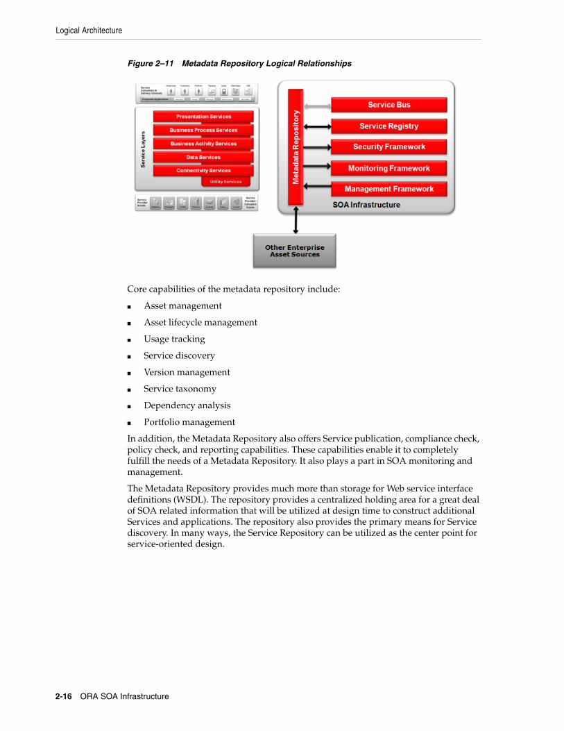
2.1.4.2 Metadata RepositoryThe primary focus of the Metadata Repository (aka Enterprise Metadata Repository or Enterprise Repository) is design-time, and it usually has no role in the runtime environment of most SOA deployments. The metadata repository interactions are shown in Figure 2–11. The metadata repository is primarily a human interface for asset capture and presentment. It has integration with the Service Registry to promote the Service interfaces and with the security framework for repository security like authentication and access control. It also has integration with other enterprise asset sources like Source Code Management (SCM) tools and file servers.
Logical Architecture
2-16 ORA SOA Infrastructure
Figure 2–11 Metadata Repository Logical Relationships
Core capabilities of the metadata repository include:
■ Asset management
■ Asset lifecycle management
■ Usage tracking
■ Service discovery
■ Version management
■ Service taxonomy
■ Dependency analysis
■ Portfolio management
In addition, the Metadata Repository also offers Service publication, compliance check, policy check, and reporting capabilities. These capabilities enable it to completely fulfill the needs of a Metadata Repository. It also plays a part in SOA monitoring and management.
The Metadata Repository provides much more than storage for Web service interface definitions (WSDL). The repository provides a centralized holding area for a great deal of SOA related information that will be utilized at design time to construct additional Services and applications. The repository also provides the primary means for Service discovery. In many ways, the Service Repository can be utilized as the center point for service-oriented design.

Logical Architecture
SOA Infrastructure Logical View 2-17
Figure 2–12 Metadata Repository
As shown in Figure 2–12, the repository can be used to store and link together Service artifacts, models and other assets. These artifacts may be related to Services design, such as Service and process models; Service development, such as contracts, interfaces, and schemas; and Service maintenance, such as usage agreements and operational metrics. The repository provides a means to organize Services into a taxonomy, link related artifacts together, and identify dependencies between Services.
2.1.4.3 Service RegistryThe Service Registry provides a standards-based runtime interface for Service assets. Service Registries are generally UDDI compliant registries that provide runtime location transparency and dynamic binding abilities. The registry also federates runtime metrics for closed loop governance.
The Service Registry has many potential purposes, however, most are better addressed today through other means. For example, the registry can be used to achieve loose coupling by offering dynamic binding to Service endpoints. Dynamic binding refers to the act of connecting a Service consumer to a producer at runtime. The consumer accesses the registry when invoking a Service and the registry determines which Service producer to use. The registry returns endpoint information to the consumer, who then accesses the appropriate endpoint.
Dynamic binding satisfies the need for loose coupling; however it requires two round trip interactions - one between the consumer and registry, and the other between the consumer and producer. It also requires the consumer to request a Service using a template, which the registry uses to locate a suitable Service provider. This programming model is much more complex than coding directly to a Service endpoint. A better model for loose coupling is the use of a Service Bus. This component logically sits between the consumer and producer, acting as a intermediary. The consumer invokes proxy Services hosted by the Service Bus, which in turn access the Service provider on behalf of the consumer. This architecture pattern provides many benefits, which has been described in Section 2.1.4.1.

Logical Architecture
2-18 ORA SOA Infrastructure
Figure 2–13 Service Registry Entities
The registry can also be used to locate Services at design-time. It typically supports the UDDI protocol for Service lookups, and offers interactive search capabilities. The registry organizes assets into a taxonomy of entities and tModels, as shown above. This allows it to organize Services into a taxonomy and make them accessible to runtime queries. One could consider the taxonomy and search to be Service discovery capabilities. However, since the structure of the registry is generally no match for what can be supported by the repository, it has been eclipsed by the repository for design-time discovery and metadata storage.
The runtime access feature does provide a benefit, even if it is not used for dynamic binding and loose coupling. It can be used to store runtime policies, such as security policies. Policies can be associated with one or more Services, and indirectly accessed via the registry. This makes the registry part of the security infrastructure.
Figure 2–14 Service Registry Logical Relationships
At runtime, the registry may be accessed by Service consumers, either to obtain Service bindings or policy references for Services they are attempting to invoke. This is represented by arrows from the Service Consumer, Services, and Service Bus boxes to the registry. The registry may leverage the Security Framework to secure its functions, and it may send events to the Monitoring Framework. The Management Framework may be used to control which Services are listed in the registry and which endpoints to use for runtime dynamic binding.
Logical Architecture
SOA Infrastructure Logical View 2-19
At design-time, the registry may exchange Service information with the Service Bus and/or Metadata Repository, in order to keep the SOA Infrastructure components synchronized. The exchange may occur in either direction, and it may be manual or automated. The Service Registry can also publish runtime statistics into the repository. This gives architects the comfort to reuse operational Services as they prove that they deliver what the contract promises.
2.1.4.4 SOA SecurityDue to its inherent distributed nature, SOA can greatly complicate the security landscape of an IT organization. In contrast to silo'ed applications, which are typically secured by adding layers of protection around the perimeter, SOA stands in favor of distributed functions and data, which are much more open, and potentially vulnerable. The Security Framework is meant to address this problem. It extends from the security infrastructure already in place to meet the challenges presented by the adoption of SOA.
The Security Framework must address the ability to secure messages, e.g., provide message-level security, as well as the ability to ensure that functions and data are accessible to the correct audience and under the right conditions. It must do so in a way that is scalable and yet manageable. This involves the unification of assets that drive security decisions, such as LDAP directories, databases, etc., as well as the centralization of policy management.
The following ideals apply to the Security Framework in order to fit the needs of SOA:
■ Standards support: Must enable choice and interoperability through the support of industry accepted security standards.
■ Security policy provisioning: Must efficiently distribute incremental updates to policy and configuration data and ensure synchronization across the enterprise.
■ Distributed policy decision-making and enforcement: Must provide a means for policy decisions to be enforced locally to meet performance requirements.
■ Centralized control of security policy and configuration data: Should provide an integrated enterprise policy "system of record" that eliminates fragmentation across disparate applications. The security management component of the SOA Infrastructure allows you to configure the policies around SOA resources centrally at design-time, and then publish the policies to the relevant security infrastructure responsible for enforcement at runtime.
■ Other Features
■ End-to-end coverage: Security should extend from the perimeter back to everything that plays a role in the SOA.
■ In transit and at rest: Messages should be protected while they are persisted in databases, queues, etc., as well as when they are being transmitted on the wire.
■ Service-oriented approach: The framework should enable security as a service, provided by consistent and re-usable infrastructure components.
■ Extensibility: The framework should provide well-defined, "pluggable" interfaces that enable it to be extended to meet future needs without rework.
■ Support for heterogeneity: The framework must be compatible with existing security products and be capable of being leveraged across a diverse array of Web servers, application servers, and custom applications built in various languages.
Logical Architecture
2-20 ORA SOA Infrastructure
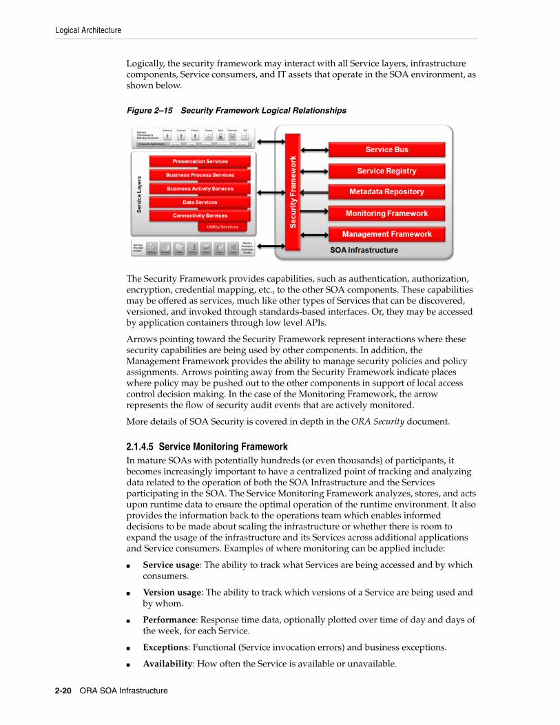
Logically, the security framework may interact with all Service layers, infrastructure components, Service consumers, and IT assets that operate in the SOA environment, as shown below.
Figure 2–15 Security Framework Logical Relationships
The Security Framework provides capabilities, such as authentication, authorization, encryption, credential mapping, etc., to the other SOA components. These capabilities may be offered as services, much like other types of Services that can be discovered, versioned, and invoked through standards-based interfaces. Or, they may be accessed by application containers through low level APIs.
Arrows pointing toward the Security Framework represent interactions where these security capabilities are being used by other components. In addition, the Management Framework provides the ability to manage security policies and policy assignments. Arrows pointing away from the Security Framework indicate places where policy may be pushed out to the other components in support of local access control decision making. In the case of the Monitoring Framework, the arrow represents the flow of security audit events that are actively monitored.
More details of SOA Security is covered in depth in the ORA Security document.
2.1.4.5 Service Monitoring FrameworkIn mature SOAs with potentially hundreds (or even thousands) of participants, it becomes increasingly important to have a centralized point of tracking and analyzing data related to the operation of both the SOA Infrastructure and the Services participating in the SOA. The Service Monitoring Framework analyzes, stores, and acts upon runtime data to ensure the optimal operation of the runtime environment. It also provides the information back to the operations team which enables informed decisions to be made about scaling the infrastructure or whether there is room to expand the usage of the infrastructure and its Services across additional applications and Service consumers. Examples of where monitoring can be applied include:
■ Service usage: The ability to track what Services are being accessed and by which consumers.
■ Version usage: The ability to track which versions of a Service are being used and by whom.
■ Performance: Response time data, optionally plotted over time of day and days of the week, for each Service.
■ Exceptions: Functional (Service invocation errors) and business exceptions.
■ Availability: How often the Service is available or unavailable.

Logical Architecture
SOA Infrastructure Logical View 2-21
■ Security violations: Attempts to use a Service without proper access rights
As shown below, the Monitoring Framework can receive run time data and events from any component in the SOA environment. SOA dashboards usually synthesize and present the information in a human friendly format.
Figure 2–16 Monitoring Framework Logical Relationships
The Service Monitoring Framework is usually more than a single product. It can be a combination of infrastructure components to instrument Service interactions, as well as functions built into the Services platforms that provide audit capabilities, usage metrics, and performance data.
Ideally, the Service Monitoring Framework receives its runtime configuration from the Service Management Framework which enables it to adapt to changes without the need for coding and redeployment.
2.1.4.6 Service Management FrameworkService management refers to the configuration of the SOA Infrastructure to control the runtime aspects of the deployment. The Service Management Framework is also used to activate the configuration at runtime. The following capabilities are commonly looked for when evaluating Service management infrastructure:
■ Security support
■ Service level agreements management
■ Logging and monitoring
■ Versioning support
■ Resource browsing
■ Environment propagation

Logical Architecture
2-22 ORA SOA Infrastructure
Figure 2–17 Management Framework Logical Relationships
The Management Framework is used to control, or manage, various aspects of the SOA environment. Therefore, the relationship is generally unidirectional. One exception is the relationship between the Management and Monitoring Frameworks. Monitoring data may feed into the Management Framework in order to automate management activities. For example, runtime performance data may automatically control resource provisioning. Likewise, security events, such as those indicative of hacking, may automatically trigger defensive measures such as the tightening of security policies or the denial of services from a particular consumer.
Another exception to the unidirectional relationship is the interaction between the Management and Security Frameworks. The Security Framework may control access to management functions, and therefore may push access control decisions out to the Management Framework.

3
SOA Infrastructure Product Mapping View 3-1
3SOA Infrastructure Product Mapping View
This section describes the physical view of the SOA infrastructure. It begins by mapping the Oracle products to the logical infrastructure components and describes each of the SOA infrastructure products in the context of the SOA capabilities. The logical architecture discussed in Chapter 2 shows two major distinct parts, Service Layers and SOA Infrastructure.
Service Layers are the architectural categorization of Services and relate to the Service implementation platform. In contrast, the SOA Infrastructure relates to the common capabilities required to build an enterprise class SOA platform.
Although the primary focus of this document is the SOA Infrastructure, this chapter also provides an overview of the technologies needed to build the Service platform in Section 3.2. Detailed product documentation is available online and the URLs are provided in Appendix A, "Further Reading".
3.1 Oracle Product Mapping - SOA InfrastructureOracle offers a comprehensive SOA solution through a suite of SOA products. Oracle Fusion Middleware products cover the needs of the SOA Infrastructure end-to-end. Figure 3–1 shows the mapping of Oracle products to the SOA logical components.
The products referred in the figure are:
■ OSB - Oracle Service Bus
■ OSR - Oracle Service Registry
■ OER - Oracle Enterprise Repository
■ OWSM - Oracle Web Service Management
■ OEM - Oracle Enterprise Manager (with SOA management pack)
■ IdM - Identity and Access Management
Note: The best and latest source of product information is the online product documentation. Links to the online documentation are provided in Appendix A, "Further Reading". This section presents version specific information like product features and standards support that are current as of the writing of this document. Please refer to the product documentation for your specific version of the product for the latest supported features and standards. The standards stated in this document may be a partial list and some may be partially supported by the products.

Oracle Product Mapping - SOA Infrastructure
3-2 ORA SOA Infrastructure
As shown in Figure 3–1, there is not necessarily a one-to-one mapping between logical architecture components and products. While some products target a specific logical need, most provide additional features, such as monitoring, management, and security.
Figure 3–1 SOA Infrastructure - Oracle Product Mapping
The centerpiece of Oracle's SOA Infrastructure offerings is the Oracle Service Bus (OSB). This product fully satisfies the requirements of a Service Bus. It also provides Service management, monitoring, and security capabilities in addition to the standard Service routing, mediation, and transformation features.
The Oracle Enterprise Repository (OER) provides a great deal of design-time capabilities. It provides a robust and flexible repository for storing, managing, and discovering all types of SOA based assets. OER also provides capabilities for quality assurance and SOA governance enforcement. These may be applied to help manage SOA based development work underway in the organization or enterprise.
Oracle Service Registry (OSR) provides a robust UDDI registry for runtime metadata information including Service descriptions (WSDL), and policies (WS-Policy). It may be used to support loose coupling through dynamic Service binding if a Service Bus is not present. Please note that the Service Bus would be a basic requirement as SOA maturity increases. OSR is also ideal for providing discovery of Services when access to a repository is not permitted.
Oracle Identity Management (IdM) Suite provides centralized security management capabilities for an enterprise wide SOA. IdM provides a comprehensive security solution that covers the full spectrum of identity management and access management. IdM is beyond the scope of this document and is covered in the ORA Security document.
Management of Services is extremely important in SOA environments, where Services are integrated, reused, and constantly changed. Oracle Enterprise Manager (OEM) simplifies monitoring and managing SOA environments. It addresses each of the

Oracle Product Mapping - SOA Infrastructure
SOA Infrastructure Product Mapping View 3-3
challenges outlined above by helping model, monitor, and manage the SOA environment.
Oracle Web Services Manager (OWSM) is a Web services security and management solution that provides the visibility and control required to deploy Web services into production. OWSM allows companies to define policies that govern Web service operations such as access, authorization, logging, and load balancing, and then wrap these policies around Web services.
The rest of this section goes through the details of each of these SOA Infrastructure products.
3.1.1 Oracle Service Bus (OSB)The category of infrastructure identified as the Service Bus represents many features including:
■ Mediation - the ability to connect consumers and producers that may use different transports, protocols, message formats, error codes, etc.
■ Message mediation and Transformation - the ability to transform messages from one format to another, aggregate data elements, and enhance message content based on business rules.
■ Routing - the ability to route requests to different endpoints at runtime based on mechanisms such as message content, business rules, security constraints, etc.
■ Composition - the ability to execute multiple steps, possibly including multiple back end requests, based on configuration, to fulfill an inbound Service request.
Oracle Service Bus (OSB) is designed to meet the needs of an enterprise-class Service Bus. In addition to the Service Bus features, OSB also provides useful monitoring, management, and security capabilities. This makes it applicable to these SOA Infrastructure components as well.
The OSB acts primarily as an intermediary that takes in messages, processes them to determine where to route them, and transforms them as specified. It receives messages through a transport protocol such as HTTP(S), JMS, File, FTP, etc., and sends messages through the same or a different transport protocol. Message response follows the reverse path. The message processing by OSB is driven by metadata specified as the message flow definition, which is created at design time, for a proxy Service in the OSB configuration.
OSB is policy driven. It enables you to establish loose coupling between Service clients and Services while maintaining a centralized point of control and monitoring.
The following features provided by OSB provide value to the SOA environment:
■ Service routing
■ Transformations
■ Mediation
■ Message flow modeling
■ Error handling
■ Quality of service
OSB supports the following industry standards:

Oracle Product Mapping - SOA Infrastructure
3-4 ORA SOA Infrastructure
3.1.2 Oracle Enterprise Repository (OER)Oracle Enterprise Repository (OER) provides the tools to manage and govern the metadata for any type of software asset, from business processes and services to patterns, frameworks, applications, components, and models. OER maps the relationships and interdependencies that connect those assets to improve impact analysis, promote and optimize their reuse, and measure their impact on the bottom line.
Core capabilities of the OER include:
■ Asset management
The primary function of OER is to provide a means to store metadata in a way that related objects can be linked together and managed.
■ Asset lifecycle management
OER includes the ability to manage Service status through the notion of registered and unregistered assets.
■ Usage tracking
OER can be used to house Consumer Contracts aka Usage Agreements, linked to Services. This makes it easy to not only see what a Service does, but who is using it.
■ Service discovery
OER facilitates Service discovery by providing a means to locate potential Services either through taxonomy navigation, or direct search.
■ Version management
The Service lifecycle and dependency tracking capabilities of OER make it part of the overall version management tool kit.
■ Dependency analysis
Along with the ability to navigate taxonomies, OER provides the capability to navigate asset relationships. One of the major benefits of using an enterprise repository is to facilitate impact analysis based on inter-dependency.
■ Portfolio management
OER, with its ability to classify Services into a navigable taxonomy, supports portfolio management. The Service portfolio manager can use this tool to track Services and Service candidates with respect to business functions, processes, and plans for future Services.
OER supports the following standards:
Topic Standards Supported
Web Services SOAP 1.2, SOAP 1.1, WSDL 1.1, WS-Addressing 1.0, WS-Policy 1.5, WS-Trust 1.3, WS-I Basic Profile 1.0, JAX-WS 2.1, JAXB 2.1
Security WS-Security 1.1, WS-SecurityPolicy 1.2, WS-SecureConversation 1.3, SAML Token Profile 1.0, SAML 1.1, SAML 1.0, WS-Security Token Profile 1.0, Username Token Profile 1.0, X509 Token Profile 1.0, WS-I Basic Security Profile 1.0
Transport HTTP 1.1, HTTP 1.0, JMS 1.1
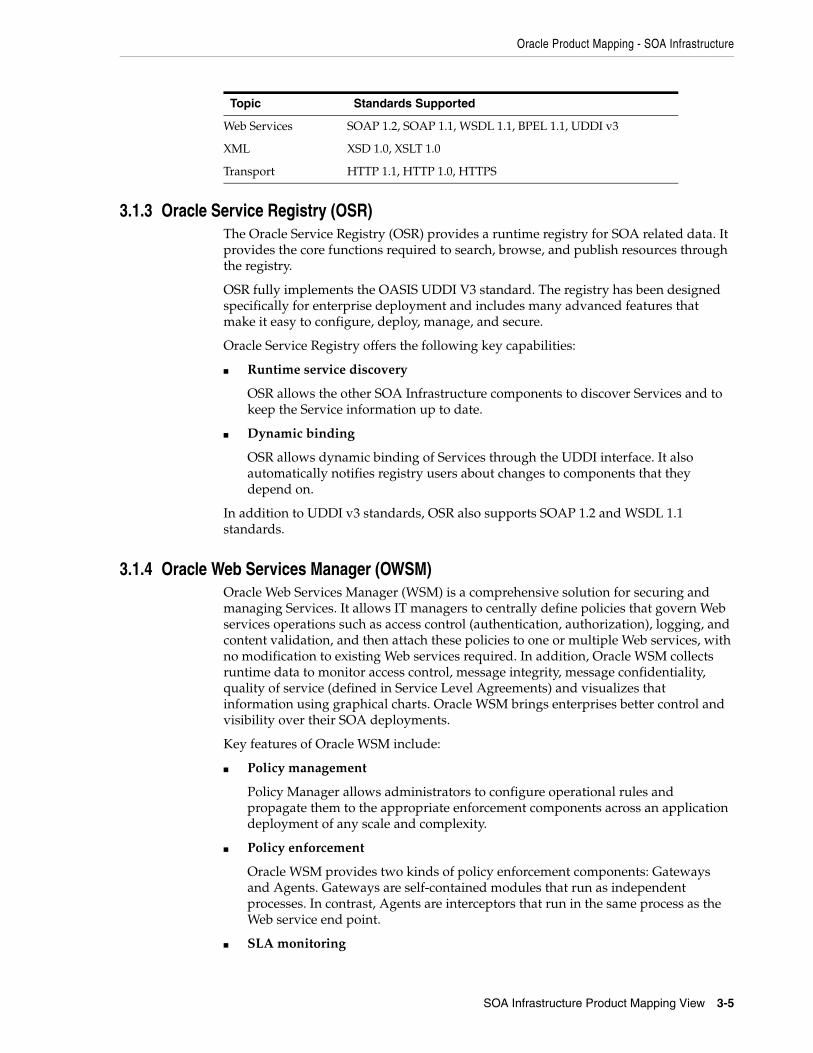
Oracle Product Mapping - SOA Infrastructure
SOA Infrastructure Product Mapping View 3-5
3.1.3 Oracle Service Registry (OSR)The Oracle Service Registry (OSR) provides a runtime registry for SOA related data. It provides the core functions required to search, browse, and publish resources through the registry.
OSR fully implements the OASIS UDDI V3 standard. The registry has been designed specifically for enterprise deployment and includes many advanced features that make it easy to configure, deploy, manage, and secure.
Oracle Service Registry offers the following key capabilities:
■ Runtime service discovery
OSR allows the other SOA Infrastructure components to discover Services and to keep the Service information up to date.
■ Dynamic binding
OSR allows dynamic binding of Services through the UDDI interface. It also automatically notifies registry users about changes to components that they depend on.
In addition to UDDI v3 standards, OSR also supports SOAP 1.2 and WSDL 1.1 standards.
3.1.4 Oracle Web Services Manager (OWSM)Oracle Web Services Manager (WSM) is a comprehensive solution for securing and managing Services. It allows IT managers to centrally define policies that govern Web services operations such as access control (authentication, authorization), logging, and content validation, and then attach these policies to one or multiple Web services, with no modification to existing Web services required. In addition, Oracle WSM collects runtime data to monitor access control, message integrity, message confidentiality, quality of service (defined in Service Level Agreements) and visualizes that information using graphical charts. Oracle WSM brings enterprises better control and visibility over their SOA deployments.
Key features of Oracle WSM include:
■ Policy management
Policy Manager allows administrators to configure operational rules and propagate them to the appropriate enforcement components across an application deployment of any scale and complexity.
■ Policy enforcement
Oracle WSM provides two kinds of policy enforcement components: Gateways and Agents. Gateways are self-contained modules that run as independent processes. In contrast, Agents are interceptors that run in the same process as the Web service end point.
■ SLA monitoring
Topic Standards Supported
Web Services SOAP 1.2, SOAP 1.1, WSDL 1.1, BPEL 1.1, UDDI v3
XML XSD 1.0, XSLT 1.0
Transport HTTP 1.1, HTTP 1.0, HTTPS

Oracle Product Mapping - SOA Infrastructure
3-6 ORA SOA Infrastructure
OWSM offers SLA monitoring features like service invocation monitoring and SLA adherence monitoring.
■ Usage tracking
OWSM offers data collection and reporting capabilities.
■ Security monitoring and audits
OWSM monitors authentication/authorization activities for all Web services and audits security violations per Web service, per operation, and per client.
■ Business process monitoring
OWSM monitors business process flows end-to-end and provides alerts via propagation of events.
■ SOA dashboard
OWSM provides an operational dashboard to display vital monitoring information that include Service and security statistics.
■ Mediation
OWSM offers out-of-the-box, native support for multiple transports and messaging models.
■ Routing
OWSM offers agent based routing capabilities. It can do content-based message routing and attachment-based content routing.
OWSM supports the following standards:
3.1.5 Oracle Enterprise Manager for SOA (OEM)Oracle Enterprise Manager is a comprehensive IT management solution that makes IT infrastructure management simpler, leading to better cost control. Enterprise Manager enables management of single instances of Oracle SOA Suite, Database, Application Server, or Collaboration Suite using standalone consoles. Enterprise Manager Grid Control is Oracle's single, integrated solution for managing all aspects of the Oracle Grid infrastructure and the applications running on it..
The Management Pack for SOA delivers comprehensive management capabilities for a SOA-based environment. By combining SOA runtime governance, business-IT alignment, and SOA infrastructure management with Oracle's rich and comprehensive system management solution, Enterprise Manager Grid Control significantly reduces the cost and complexity of managing SOA-based environments.
Oracle Enterprise Manager Grid Control - Composite Application Monitor and Modeler (CAMM) analyzes J2EE and SOA applications to capture the complex
Topic Standards Supported
Web Services SOAP 1.2, SOAP 1.1, WSDL 1.1, WS-Policy
Security WS-Security 1.0, WS-SecurityPolicy 1.2, WS-SecureConversation 1.3, SAML Token Profile 1.0, SAML 1.1, SAML 1.0, WS-Security Token Profile 1.0, Username Token Profile 1.0, X509 Token Profile 1.0, Encryption algorithms: AES-128, AES-256, 3-DES, Message Digests: MD5, SHA-1, XML Signature, XML Encryption, PKI: RSA v1.5, DSA, JKS
Transport HTTP 1.1, HTTP 1.0

Oracle Product Mapping - Service Platform
SOA Infrastructure Product Mapping View 3-7
relationships among various application building blocks in its AppSchema model. Using the insights stored in AppSchema, CAMM is able to deliver an environment that self-customizes out-of-the-box, evolves with change, minimizes expert involvement, and delivers a holistic, service-oriented view across heterogeneous environments.
The key features of the Oracle Enterprise Manager for SOA include:
■ SLA management
■ Thresholds, alerts, notifications, and SLAs in OEM on external metrics
■ Business KPIs can be used with system metrics to compute SLA
■ OEM Services dashboard displays SLA compliance
■ Logging and monitoring
OEM provides administrators managing SOA environments with a consolidated browser-based view of the entire enterprise; thereby enabling them to monitor and manage all of their components from a central location.
■ Performance management
OEM measures and monitors the availability and performance of services for historical trending, troubleshooting, and root cause analysis purposes.
■ Environment propagation
OEM collects configuration information for the server, domains, and processes. It automates the deployment of resources. Scheduling capability is also provided by OEM.
■ SOA dashboard
Using EM Grid Control's graphical monitoring dashboards, administrators, managers, and business owners gain real-time understanding of the status of services in a single view. Monitoring dashboards provide top-level views of individual or groups of services, as well as system-level views describing the relationships and status of IT system components.
3.2 Oracle Product Mapping - Service PlatformServices that belong to the layers discussed in Chapter 2 are developed and deployed on various platforms referred to as the Service platform. Oracle offers a slew of technologies suitable for building one or more of the layers of these Services. Figure 3–2 maps the Oracle products to the SOA Service Layers.

Oracle Product Mapping - Service Platform
3-8 ORA SOA Infrastructure
Figure 3–2 Service Platform - Oracle Product Mapping
The products referred in Figure 3–2 are listed by the respective layers below:
■ Presentation Services:
■ OWC - Oracle WebCenter (Content, Portal, Sites, Social)
■ Business Process Services:
■ BPEL - BPEL Process Manager
■ OBPM - Oracle Business Process Management
■ Business Activity Services:
■ BPEL - BPEL Process Manager
■ OB2B - Oracle B2B Integrator
■ OBR - Oracle Rules
■ OWLS - Oracle WebLogic Server
■ Data Services:
■ BPEL - BPEL Process Manager
■ ODSI - Oracle Data Services Integrator
■ ODI - Oracle Data Integrator
■ OCOH - Oracle Coherence
■ OWLS - Oracle WebLogic Server
■ Connectivity Services:
■ OCEP - Oracle Complex Event Processing
■ OIA - Oracle Integration Adapters
■ OB2B - Oracle B2B Integration

Oracle Product Mapping - Service Platform
SOA Infrastructure Product Mapping View 3-9
■ OWLS - Oracle WebLogic Server
These products are briefly discussed in the following sections. Most of these technologies are covered in detail in the respective Enterprise Technology Strategies (ETS) documentation. A list of these documents can be found in Appendix A, "Further Reading". For example, the products mapped to the Business Process Services layer such as BPEL Process Manager and OBPM are covered in the BPM ETS Perspective documentation set.
3.2.1 BPEL Process Manager (BPEL PM)BPEL PM is a business process orchestration engine that implements the Business Process Execution Language (BPEL). BPEL-PM provides the ability to quickly build and deploy orchestrations and business processes in a standards-based manner.
Section 4.2.2 compares and contrasts orchestration and mediation. BPEL PM plays a key role in providing orchestration capabilities. BPEL PM provides a platform to build business process and Business Activity Services. It can be used to build composite Services and business processes by orchestrating existing Services and by implementing new business logic. BPEL PM has built-in integration services that allow connectivity to a number of legacy systems through adapters and native protocols.
Figure 3–3 BPEL Process Manager
As shown in Figure 3–3, BPEL provides a platform and capabilities to build versatile Services with partner, services, system and people integration. BPEL PM's built-in integration services enable developers to easily leverage advanced workflow, connectivity, and transformation capabilities from standard BPEL processes. These capabilities include support for XSLT and XQuery transformation as well as bindings to hundreds of legacy systems through JCA adapters and native protocols. Human workflow services such as task management, notification management, and identity management are provided as built-in BPEL services to enable the integration of people and manual tasks into BPEL flows. The extensible WSDL binding framework enables connectivity to protocols and message formats other than SOAP. Bindings are available for JMS, email, JCA, HTTP GET, POST, and many other protocols enabling simple connectivity to hundreds of back-end systems.

Oracle Product Mapping - Service Platform
3-10 ORA SOA Infrastructure
BPEL PM supports several open standards in addition to BPEL4WS. These standards include WSIF, WSDL, SOAP, UDDI, JMS, WS-ReliableMessaging, JCA, XQuery, XPath, XSLT and WSIL.
3.2.2 Oracle Business Process Management (OBPM)OBPM is a complete set of tools enabling collaboration between business and IT to create, automate, execute, and optimize business processes. Human centric and document centric business process services can be built efficiently using OBPM. The processes could be developed as persistent and long-running or transactional. OBPM also provides design time tools to analyze, design, simulate and optimize the business processes.
In OBPM, business processes are built using the XML Process Definition Language (XPDL) and BPMN standards.
3.2.3 Oracle Business to Business Integration (OB2B)OB2B provides a single integrated solution for rapidly establishing online collaborations and automated processes with your business partners. It provides capabilities to manage trading partners and documents with support for a variety of information exchange mechanisms.
In addition to the gateways that provide connectivity to trading partners, OB2B also provides other capabilities to build business activity services. It can easily be integrated with other Oracle SOA products like OSB and BPEL PM to provide an end-to-end business process implementation platform. OB2B provides connectivity services by supporting a number of adapters including EDI and RosettaNet adapters.
OB2B supports a number of industry standards including: EDI, UCCnet, RosettaNet, CIDX, PIDX, VICS, ebXML, UBL, SOAP, AS2, ebMS, cXML, UN/EDIFACT, UBL, X12, HL7 and OAG.
3.2.4 Oracle Business Rules (OBR)OBR evaluates rules rapidly using a light-weight, high-performance rules engine. It provides a platform to build decision services which are a type of business activity services. Decision services enable business rules to be invoked as Web services from BPEL PM or other service orchestration frameworks. The decision service tooling in BPEL PM provides seamless integration between BPEL PM and OBR.
It is a best practice to decouple reusable business rules from Service implementations regardless of the service layer the Service belongs to. OBR provides the capabilities to achieve this.
3.2.5 Oracle WebLogic Server (OWLS)OWLS is a J2EE application server that provides a robust and scalable platform to build and run Services. As shown in Figure 3–2, OWLS can be used to build business activity, data, and connectivity Services using standards based technologies like J2EE, Web services, EJB, and JDBC. OWLS is omnipresent in the Service platform as it is the underlying container for most of the products shown in the diagram. While it is possible to implement most types of Services from scratch using OWLS, other products might offer value-add on top of OWLS to increase productivity of Service development and to hide complexity underneath.

Oracle Product Mapping - Service Platform
SOA Infrastructure Product Mapping View 3-11
OWLS support a number of industry standards in the areas of Java, J2EE, Web services, security, and communication. Appendix A provides a link to the full list of standards supported by OWLS.
3.2.6 Oracle Coherence (OCOH)Coherence provides in-memory data grid capability to the Data Services layer. It provides replicated and distributed (partitioned) data management and caching services on top of a reliable, highly scalable, peer-to-peer clustering protocol. Although Coherence is not a Service implementation tool, it adds data caching, failover and high availability capabilities by means of the data grid and play a key role in improving Service performance.
3.2.7 Oracle Data Services Integrator (ODSI)ODSI provides the ability to quickly develop and manage federated, bidirectional (read and write) Data Services for accessing single views of disparate information in a standards based, declarative manner.
ODSI provides a wide array of data services designed to improve data access from disparate data sources for a wide range of clients. Using such services, organizations can create virtual databases that can more quickly and accurately model their dynamic enterprise.
Data Services encapsulate the logic for reading, writing, creating, updating, and deleting information, insulating data consumers from having to contend with multiple data source formats and connection mechanisms.
ODSI supports the latest Web Services standards that include SOAP, UDDI and a slew of XML based standards including XQuery 1.0 and XPath 2.0.
3.2.8 Oracle Data Integrator (ODI)ODI is a next-generation Extract Load and Transform (E-LT) technology that offers the productivity of a declarative design approach, as well as the benefits of a platform for seamless batch and real-time integration.
Data integration provides the important aspects for moving data and turning it into re-usable information – it acts as a key enabler for each architecture principle (e.g. SOA, BI, or Data Warehousing) and can also act as a key bridge between them. ODI provides high-volume, high-performance, bulk data movement and transformation capabilities to the Service platform and exposes rapid data integration as Services that can easily be consumed for process orchestration.
ODI’s standards support includes: Web Services standards, LDAP, SQL, JDBC and ODBC.
3.2.9 Oracle Complex Event Processing (OCEP)OCEP provides a rich, declarative environment for developing event processing applications to improve the effectiveness of your business operations. Oracle CEP can process multiple event streams to detect patterns and trends at real time and provide enterprises the necessary visibility via Oracle Business Activity Monitoring (Oracle BAM) to capitalize on emerging opportunities or mitigate developing risks.
OCEP is a key element of Event Driven SOA (EDSOA) and provides inbound and outbound connectivity services. OCEP includes out of the box adapters for JMS and HTTP connectivity. OCEP Adapter SDK provides tools to create custom adapters that

Oracle Product Mapping - Service Platform
3-12 ORA SOA Infrastructure
listen to incoming data feeds. This allows custom connectivity services to be developed and deployed.
OCEP is discussed at great length in the EDA ETS documentation.
3.2.10 Oracle Integration Adapters (OIA)OIA uses standards based on the J2EE platform to create a service-orientated approach to unlocking the assets that have evolved in IT environments. OIA provides adapters to expose Connectivity Services to a number of backend systems including packaged applications, mainframes, legacy systems, technologies, and protocols. OIA includes a lightweight adapter SDK that enables any JCA-compliant adapter to be rapidly integrated with the SOA platform.
OIA is fully standards-based ond is compliant with both the J2EE Connector Architecture (JCA) and Web Services Architecture. OIA standards support includes JCA 1.5, XML, WSDL and WSIF.
3.2.11 Oracle WebCenter (OWC)OWC is a comprehensive collection of components used to create intuitive portals, composite applications, and mash-ups.
3.2.11.1 Oracle WebCenter Portal Oracle WebCenter Portal is the best-of-breed portal framework for creating highly interactive composite applications in a SOA environment with a powerful, integrated set of design-time tools for Java developers and strong support for standards. This framework includes a rich, graphical environment for developing presentation services, portals as well as browser-based assembly tools for business experts. WebLogic Portal simplifies the production and management of custom-fit portals, allowing you to leverage a shared services environment to roll out changes with minimal complexity and effort.
3.2.11.2 Oracle Webcenter ContentOracle Webcenter Content is a unified enterprise content management platform that enables document management, web content management, digital asset management, and records retention functionality to build the business applications. Oracle WebCenter Content includes Oracle Content Portlet Suite that implements a number of interaction portlets such as Search portlet, Library portlet and Workflow queue portlet. Content management and content presentation functions can be implemented as reusable presentation services that can be composed into standards based portals.
3.2.11.3 Oracle Webcenter SitesOracle WebCenter Sites offers advanced yet easy-to-use capabilities for creating a rich and engaging online experience for customers across Web, mobile, and social channels, to build loyalty, drive customer acquisition, and reduce operational costs. Oracle WebCenter Sites gadgets provide site visitors with the ability to customize their own online experience. With Oracle WebCenter Sites’ gadget capabilities, organizations can create customizable dashboards made up of gadgets (small applications) that can then be personalized by site visitors. Gadgets can consist of lists of articles, image slideshows, calculators or analyzers of data, blog entries, videos, or any other content type

Oracle Product Mapping - Service Platform
SOA Infrastructure Product Mapping View 3-13
3.2.11.4 Oracle WebCenter SocialBy socializing of enterprise applications, business processes, and content, Oracle WebCenter Social enables the social business. By providing a collaboration and networking platform that connects applications, processes and content to people as well as to each other, Oracle WebCenter Social provides a system that engages the individual rather than being yet another system that demands action. This system allows for cross-enterprise knowledge rather than adding to the silos of lost information.

Oracle Product Mapping - Service Platform
3-14 ORA SOA Infrastructure

4
SOA Infrastructure Deployment View 4-1
4SOA Infrastructure Deployment View
This section describes the deployment view of the SOA Infrastructure covering an example topology, segregated and federated deployments, best practices, and architecture trade-offs.
4.1 Deployment Models
4.1.1 Segregated DeploymentThe approach, recommended by Oracle, to Services deployment is the separation of Services from applications and the grouping of Services with similar availability needs. To accomplish this, projects must be logically divided into shared and non-shared parts. The shared parts become Services, while the non-shared parts become ordinary applications. Development of these assets can be done by the same team; however, it is important that they are constructed in a way that allows them to be deployed separately, as illustrated below in Figure 4–1.
Figure 4–1 Segregated Deployment
4.1.2 Federated Deployment

Deployment Models
4-2 ORA SOA Infrastructure
During the initial stages of SOA maturity, as with most IT initiatives, SOA initiatives seem to work from the bottom up. Groups (lines of business, portfolios, divisions, etc.) begin to experiment with SOA and embrace it independently from each other. They deploy Services and SOA Infrastructure within the boundaries of their organization. And often they are responsible for maintaining their own assets. This leads to the notion of SOA domains.
The boundaries of a SOA domain generally fall along major organizational boundaries. The reason is based on funding and administrative responsibility. As organizations are able to fund SOA initiatives, SOA will grow and evolve. Funding for infrastructure is often absorbed at the portfolio or project level. This promotes a more localized SOA domain, different than if funds were allocated for infrastructure at the corporate level.
Organizations must also be willing to trust that Services and infrastructure they depend on will be available. They need assurances that reliability will not be impacted. Maintaining authority over, and responsibility for, computing resources is one way to achieve a level of comfort with regard to system reliability. For this reason SOA domains may align somewhat with operational boundaries, i.e., each organization that has an operations team will establish and maintain its own SOA domain.
The natural occurrence of multiple SOA domains within a company does not need to be a detriment to enterprise SOA. It is a result of increasing SOA maturity within the organization. It is important to view these domains as federated enterprise-wide deployments rather than multiple silo'ed departments. This requires the establishment of an overarching Reference Architecture that dictates such things as interoperability standards, Service discovery techniques, and Service usage guidelines. With this in place, the company can have the best of both worlds: localized control and enterprise-wide SOA.
There are many patterns to support federated infrastructure deployments. The way to determine how it should work for a particular company should begin with the Service engineering process. More specifically, who is responsible for developing and maintaining Services. If a centralized "Service Factory" model is used, then Services and infrastructure may be needed at the enterprise level. Each organization within the enterprise may optionally deploy services and infrastructure to support Services that have a local scope, or fall outside the purview of the Service Factory. An example of this is illustrated in Figure 4–2.
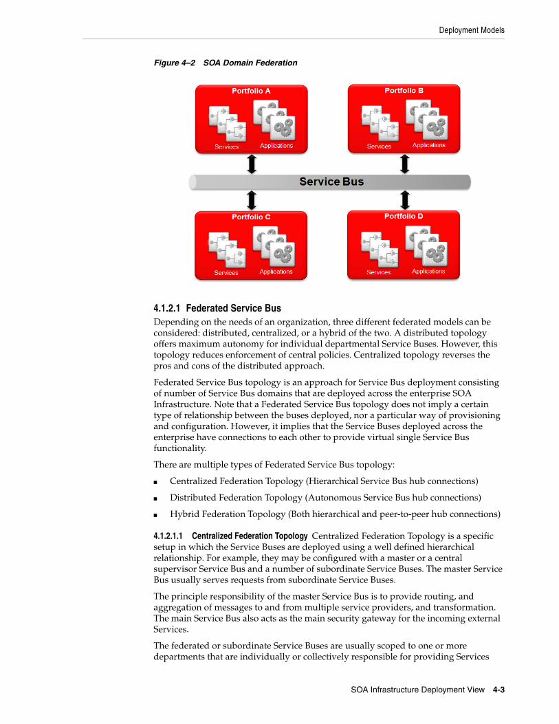
Deployment Models
SOA Infrastructure Deployment View 4-3
Figure 4–2 SOA Domain Federation
4.1.2.1 Federated Service BusDepending on the needs of an organization, three different federated models can be considered: distributed, centralized, or a hybrid of the two. A distributed topology offers maximum autonomy for individual departmental Service Buses. However, this topology reduces enforcement of central policies. Centralized topology reverses the pros and cons of the distributed approach.
Federated Service Bus topology is an approach for Service Bus deployment consisting of number of Service Bus domains that are deployed across the enterprise SOA Infrastructure. Note that a Federated Service Bus topology does not imply a certain type of relationship between the buses deployed, nor a particular way of provisioning and configuration. However, it implies that the Service Buses deployed across the enterprise have connections to each other to provide virtual single Service Bus functionality.
There are multiple types of Federated Service Bus topology:
■ Centralized Federation Topology (Hierarchical Service Bus hub connections)
■ Distributed Federation Topology (Autonomous Service Bus hub connections)
■ Hybrid Federation Topology (Both hierarchical and peer-to-peer hub connections)
4.1.2.1.1 Centralized Federation Topology Centralized Federation Topology is a specific setup in which the Service Buses are deployed using a well defined hierarchical relationship. For example, they may be configured with a master or a central supervisor Service Bus and a number of subordinate Service Buses. The master Service Bus usually serves requests from subordinate Service Buses.
The principle responsibility of the master Service Bus is to provide routing, and aggregation of messages to and from multiple service providers, and transformation. The main Service Bus also acts as the main security gateway for the incoming external Services.
The federated or subordinate Service Buses are usually scoped to one or more departments that are individually or collectively responsible for providing Services

Deployment Models
4-4 ORA SOA Infrastructure
using that bus. The rationale behind such a hierarchy is to allow individual organizational units to be able to effectively control all aspects of the Services that they provide or are otherwise responsible to provide.
Figure 4–3 Centralized Federation Topology
This topology requires all the divisional or federated Service Buses to route the requests to one another via the central backbone Service Bus.
Figure 4–3 depicts multiple SOA Domains, one at the enterprise level and two at the portfolio level. Services offered at the enterprise level are owned and managed by a corporate Service Factory team. They are made available via the ESB associated with that domain.
Each portfolio can host its own local Services. These are only available within the portfolio, otherwise they are promoted to the enterprise level. Applications within the local portfolio domains can leverage local Services as well as enterprise Services. Each domain contains a registry to advertise Services within that domain. The registry at the enterprise level is available to all domains; whereas, the registry within the portfolio domains is private to that domain.
This example requires the configuration of multiple ESBs. There are basically two ways to configure them: as gateways to and from the domain, or as endpoints directly exposed to service consumers of adjacent domains. In this example the arrows indicate a gateway configuration. This means that traffic from one domain to another must pass through two ESBs - the local ESB and the remote ESB. Proxy services must be configured in the local (portfolio) domain in order to access enterprise Services. This adds management overhead, but in return offers the ability to mediate messages, transports, and security, between domains. Other deployment variations may include single instances of the ESB and/or registry.
4.1.2.1.2 Distributed Federation Topology Distributed Federation Topology, consists of multiple autonomous Service Buses communicating with each other directly as peers. Each Service Bus hosts a number of Services and accepts requests from a number of clients. There is no central hub that all requests pass through.

Deployment Models
SOA Infrastructure Deployment View 4-5
Figure 4–4 Distributed Federation Topology
The distributed topology for federation involves direct Service invocations across different divisions.
4.1.2.1.3 Hybrid Federation Topology Hybrid Federation Topology is one that utilizes both central and distributed Service Bus topologies. Although there is a central bus in the topology, bus-to-bus communication is also allowed under certain circumstances. There can be large variations of this topology since there many topology options between centralized and distributed.

Deployment Models
4-6 ORA SOA Infrastructure
Figure 4–5 Hybrid Federation Topology
4.1.2.1.4 Drivers for Federated Service Bus Configurations There are two main categories of drivers for distributed Service Buses. The first category of drivers is related to the needs of the large organizations to manage different parts of the organizations in a federated manner involving separation of the responsibilities and policies among various organizational units. The second category is technical which has some similarities to the drivers for having multiple Web servers.
While centralized federation of the Service Buses can result in a number of the benefits described above, centralization can also incur some costs.
■ Some federation configurations may create one or more additional network hops which may impact performance. Care must be taken to not take the federation to extreme limits.
■ A large number of Service Bus instances can create their own management problems. Hence, for a small number of Services, homogeneous buses (such as single protocol, having similar QoS and SLAs), or buses having similar security and access policies, federation of the Service Buses should be considered carefully.
4.1.2.2 Federated RegistriesThe discovery of Services in other domains is accomplished via a federated registry, as illustrated below in Figure 4–6.
Federation will allow developers to discover Services in other domains without having to navigate their Web browser from one domain to the other. It will also allow Services to be organized in an enterprise taxonomy as opposed to multiple unique domain taxonomies. While the public registry should be federated, the local domain should not.

Deployment Models
SOA Infrastructure Deployment View 4-7
Deployment options for federated registries will depend on the actual product that is chosen. If the registry is only used for discovery (i.e., dynamic binding is not permitted) then high availability will not be such an issue.
Figure 4–6 Federated Registry
4.1.3 Product Deployment StrategiesEach Oracle infrastructure product has its own unique deployment options and considerations. Most are deployed to applications clusters, such as Oracle WebLogic Server (OWLS), either in the form of applications running in the server environment or components of other applications. The following sections provide a brief look at an example topology and the associated products. Detailed installation and configuration information is available online. It is recommended that online documentation is used to architect any solution as it is far more descriptive than this document is intended to be, and it is updated with each new product version.
4.1.3.1 SOA Infrastructure TopologyThe broad portfolio of Oracle middleware products offer the capabilities required to build a comprehensive SOA Infrastructure. The pattern of evolution of this infrastructure might vary depending on the goals and SOA maturity of the organization, but nevertheless, an optimized SOA Infrastructure will require the components depicted in Figure 4–7. It shows the implementation of the SOA Infrastructure using the Oracle SOA Fusion Middleware products organized by common tiers. The diagram also shows other related components like BAM, BPEL, and security that will be covered in other documents.

Deployment Models
4-8 ORA SOA Infrastructure
Figure 4–7 Oracle SOA Infrastructure Topology (Sample)
The client tier shows the external clients accessing the Services in the trusted network through a DMZ. There are potentially internal consumers within the organization consuming the Services. OWSM client agents are configured on the client side to achieve policy enforcement on the client side and message encryption. OWSM gateways manage Services from multiple providers and are deployed independently to control access and meter Services. OWSM agents are deployed on the Service Bus or on the provider containers to implement last mile security.
The OSB is deployed in a clustered environment and is a central element of the SOA Infrastructure. It can be scaled horizontally or can be deployed in more sophisticated federated fashion, as discussed in Section 4.1.3. The OSB and the registry are integrated so that the bus can import the Services and subscribe for notifications. OSB can also publish the Services directly to the registry although it is discouraged from a best practice perspective. The best practice is to promote Services through the registry chain with the Service promotion process. OWSM can also be integrated with the registry for automatic discovery and registration of Services.
Oracle Enterprise Repository is shown in the diagram pushing the Service metadata to the registry. This generally happens in the development environment publication registry. The testing environment has an intermediate registry which gets the Services through the promotion workflow process. The production environment registry is a discovery registry. The intermediate registry pushes the Service metadata to the discovery registry through the approval process. This process is shown in Figure 4–8.

Deployment Models
SOA Infrastructure Deployment View 4-9
Figure 4–8 Service Promotion
Although not considered part of the core SOA Infrastructure, some of the products shown in the diagram provide a platform to implement the Services. BPEL PM, OBPM, WCS, and ODSI are some of the examples.
For simplicity, this diagram shows only the key interactions in the SOA Infrastructure and not all interactions. The administration servers are not shown explicitly in this implementation diagram but depending on the size and complexity of the deployment multiple domains and multiple administration servers might be required.
A number of factors influence the way SOA is deployed in an enterprise, including the Service deployment and ownership model, availability of shared infrastructure, the way Services are defined and used, availability and scalability concerns, security concerns, private and public Services, the number of organizations involved, and the number of data centers involved. Each of these factors helps to determine how Services, servers, and SOA elements, such as ESBs and registries, should be deployed. A sample deployment model for a single-segment SOA Infrastructure system is depicted in Figure 4–9:
Figure 4–9 SOA Infrastructure Physical Deployment Model

Deployment Models
4-10 ORA SOA Infrastructure
The sample approach illustrates the positioning of infrastructure elements across three separate networks. The production network is a protected network that connects applications running in the production environment. This is an existing network that may actually be made up of several physical networks linked together. Existing applications can access UDDI registry services for dynamic binding and Service discovery. They can also access the Service Bus, which hosts proxy services that provide indirect mediated access to Services in the SOA environment.
A Services Network is shown connecting elements of the SOA environment. This network provides connectivity between the Service Bus and Services in the services cluster. It also links to the registry and security services. The reason it is separated from the production network is to eliminate the possibility to access Services without going through the Service Bus. Other methods include access control mechanisms, such as id and password protection, digital certificates, mutual authentication, etc. These can also be used by the Services to restrict access to the Service Bus; thereby eliminating direct access by Service consumers.
The third network is a maintenance network which is used by the Operations Team to administer various infrastructure components. This network connects to all systems in the production environment as well as all maintenance systems. It allows administration servers and operations terminals access to control production applications, Services, and infrastructure.
4.1.3.2 Oracle Service Bus (OSB) DeploymentScalability of Services Bus is achieved by clustering the instances. Oracle Service Bus (OSB) runs within a application server cluster. Clustering allows OSB to run on a group of servers that can be managed as a single unit. In a clustered environment, multiple machines share the processing load. OSB provides load balancing so that resource requests are distributed proportionately across all machines. An OSB deployment can use clustering and load balancing to improve scalability by distributing the workload across nodes.
The OSB console is used to design and compose the Service wiring between consumers and producers. It is also used to set up the management and monitoring capabilities that will be enforced at runtime. These capabilities are then propagated to the runtime environment for execution. The OSB admin server, which hosts the console, is not required to be active in order for the runtime services of the OSB to function correctly.
4.1.3.3 Oracle Enterprise Repository (OER) DeploymentGenerally only one instance of the repository is deployed with an optional additional instance for training and testing purposes. Since there should be one place where all the assets should be maintained with appropriate lifecycle statuses, one instance of repository should be maintained. The repository can be deployed on application servers like OWLS and can be clustered for high availability. Repository is not part of the runtime infrastructure but it is a critical component of the design-time activities. So generally a single, non-clustered instance would be sufficient for most use cases. OER provides browser based interface for managing and accessing the assets in the repository.
4.1.3.4 Oracle Service Registry (OSR) DeploymentThe Oracle Service Registry (OSR), when utilized, can be deployed in a separate clustered environment, or within an existing OWLS cluster. The primary purpose of the OSR is to provide a runtime metadata registry for runtime discovery and
SOA Infrastructure Best Practices
SOA Infrastructure Deployment View 4-11
invocation of services through the use of the UDDI interface. A Web services interface is also available to the registry if needed.
OSR is shown deployed to its own OWLS cluster, which allows it to be managed independently from other applications, Services, or infrastructure components. Management features are built into the runtime deployment, which means there is no additional remote administrative process deployed for OSR. Management is performed by accessing the production instances directly via a Web browser.
4.1.3.5 Oracle Web Services Manager (OWSM) DeploymentOracle Web Services Manager (OWSM) is comprised of a number of management components that run on production management systems, as well as remote agent components that are co-located with service providers and consumers. The management capabilities can be divided into categories such as: service level monitoring, logging, and exception handling. Each can be deployed to different systems as performance and load characteristics warrant. Management components may be deployed to OWLS clusters. OWSM agents are available in two varieties: gateways and agents. Gateways are deployed standalone whereas the agents are codeployed with the endpoints.
Please note that Figure 4–9 depicts an OWSM agent deployed with one of the application clusters but not with the Services. The purpose is to show OWSM as a client side agent that measures round trip performance for a particular client. In this scenario it is not represented as the provider of security or mediation.
Since proxy services are considered the true Service interface, it naturally follows that the Service provider endpoint is the Service Bus. Logic behind this interface, including the interface to back end business Services, are considered part of the Service implementation. Therefore, it also follows that if OWSM were to be deployed at each Service endpoint, it would be deployed with OSB, not with the Services in the Services Cluster.
4.2 SOA Infrastructure Best PracticesThis section describes best practices with respect to SOA Infrastructure.
4.2.1 OSB Architecture Trade-offsOSB provides a very flexible, feature-rich Service Bus. Its role as an active intermediary requires it to be positioned between the Service consumer and provider.
4.2.1.1 Bus ArchitectureThe approach taken by OSB is somewhat "hub-based" in that it is positioned in the middle of many consumers and providers. A bus architecture is often drawn as a pipe that messages move through. This is somewhat misleading in that the pipe is essentially the network between components and OSB in another endpoint on the network. To be more specific, OSB is a midpoint on the network with respect to Service providers and consumers.
4.2.1.2 Endpoint DeploymentAnother option in terms of Service Bus architecture is an endpoint deployment. This involves the installation of Service Bus components at every endpoint, rather than one component at the midpoint. Endpoint components, usually called agents, are synchronized in such a way that they work in harmony, following a common configuration. The benefit of this approach is there is only one network hop. Usually
SOA Infrastructure Best Practices
4-12 ORA SOA Infrastructure
the real Service provider endpoint is advertised since the agent intercepts inbound and outbound traffic as part of a filter or handler. It also provides the ability to measure performance and provide security controls at the endpoints where it is most useful.
The downside of endpoint deployments is primarily two-fold. First, it can become a management nightmare since there can be hundreds of endpoints and many different technologies involved. The likelihood is high that some platform or Service interface technology in use will not be supported. Second, lightweight endpoints generally do not provide features such as content-based routing, message transformation, and Service composition. For these reasons the midpoint solution OSB provides is recommended.
4.2.1.3 Service Bus ApplianceAnother option to OSB is a Service Bus appliance, or firmware-based solution. These may provide greater throughput at the cost of limited functionality and flexibility. Their downside is that they are usually less flexible, provide fewer features, and are harder to configure. One must consider these trade-offs when evaluating Service Bus components.
4.2.1.4 Message BusA final option to consider is the use of message bus products as a Service Bus. There has been somewhat of a convergence of products in this regard, with Service Bus features being added to message bus products. Rather than provide a point-by-point product comparison in this document that will quickly become dated, it would be better to simply recommend choosing the right tool for the job. A Service Bus provides many critical features and supports standard integration protocols. Message bus products tend to use proprietary integration techniques and cost more. Features, price, and standards support help drive the need for pure-play Service Bus products, such as OSB.
4.2.2 Mediation versus OrchestrationAnother convergence taking place is in the orchestration of activities with respect to business Services and business processes. OSB provides the ability to design process flows that control a series of activities to fulfill Service requests. The process flows are relatively simple, and are meant to support the modeling and orchestration of technical operations pertaining to the execution of a Service. The intent of OSB is to act as a proxy, or mediator for Service providers. Though the proxy services are represented as a flow of activities, the Service logic itself belongs to the Service provider. In addition to invoking the Service provider, OSB flows may include activities to support logging, routing, message transformation, and security. These activities generally fall under the category of common infrastructure, or foundational activities (as opposed to business logic / decision making activities).
More sophisticated orchestration is available with other products such as Oracle BPEL Process Manager and Oracle BPM. These products are designed for orchestration, and can expose orchestrations as Services. It is easy to see where they may be thought of as being interchangeable. OSB, BPEL PM, and OBPM engines all provide some form of process or flow modeling with exposure as Services.
The difference between OSB and the BPM products is that OSB is designed as a configuration-driven infrastructure component. This allows it to be used by multiple project teams, supporting many applications and Services, without being tied to any project's delivery cycle. Though it supports custom coding, it does not require any such coding or deployments in order to add, change, or remove proxy services. This makes it ideal as a mediator in the form of a common infrastructure component. It

SOA Infrastructure Best Practices
SOA Infrastructure Deployment View 4-13
provides the mediation capabilities that form an intelligent, loose coupling between Service consumers and providers. It is configured by Operations staff or developers and ideally contains no business logic.
OBPM and BPEL PM orchestrations are generally used as Service provider platforms. They support the modeling of business or technical orchestrations that can be exposed as Services. BPEL PM is well suited for technical orchestrations. An example is data synchronization, where complex data update scenarios can be modeled and executed.
Orchestration models may be represented using an XML notation. Common notations include BPEL and XPDL. The intent of standardizing this notation is to allow tools and products from multiple vendors to interact and to eliminate vendor lock-in.
Regardless of the standard chosen, the focus of products aligned with these standards is on business process modeling and execution. Business processes are created by business analysts to define the flow of activities for business functions. The process models are executed by BPM tools. Processes (and sub-processes) may be exposed as Services in a SOA. Like other types of Services, process-based Services should also be mediated. Therefore, the recommended approach is to use OBPM, BPEL, BPMN, and other process modeling tools as Service providers, and use OSB as the mediator. This supports a beneficial separation of concerns, where each tool is used by its target audience for its intended purpose. Business logic resides in the business process modeling tool, readily available to the business analysts, while mediation activities reside in the Service Bus, which is supported and configured by operations and/or development personnel.
4.2.3 OWSM Architecture Trade-offsThe OWSM distributed architecture stands in stark contrast to the centralized nature of OSB. Both provide similar features, such as security enforcement, routing, message transformation, and the ability to monitor performance and usage, and log access to Services.
A key benefit of OWSM (with respect to these common features) is its ability to instrument the client or deploy client agents. This allows it to measure response time from the client's perspective rather than from a point in the middle. It also has the ability to scale out and yet offer centralized management.
OSB clusters follow a more silo'ed approach where each cluster is maintained individually. Each cluster must be updated when Services are provisioned or changed. In addition, OWSM offers management capabilities that other Oracle products (including OSB) do not offer, such as message-level security policy management, SLA management, and runtime Service and dependency detection.
The downside of adopting such a distributed architecture is the need to install it at every endpoint. This can create management challenges when it comes to maintaining these deployments as the number of endpoints escalates. It is also prone to technology limitations. For instance, it is unlikely that agents will be available for every platform that hosts Services, and even less likely for every type of client (Service consumer). This opens up the possibility that holes will exist in the SOA environment where OWSM cannot be applied. For these reasons, OWSM is positioned as providing essential capabilities of Monitoring, Management, and Security Frameworks.

SOA Infrastructure Best Practices
4-14 ORA SOA Infrastructure

5
SOA Infrastructure Process View 5-1
5SOA Infrastructure Process View
The Process View describes the runtime interactions of the various components of the SOA Infrastructure. In this section, we will focus on the runtime interactions between various logical components that make up the SOA Infrastructure.
5.1 Runtime SOA Infrastructure ProcessAt runtime, the SOA Infrastructure acts upon the configuration constructed at design- time. Primarily this includes the Service mediation functions performed by the Service Bus, the security functions, such as authentication, authorization, auditing, encryption, and policy enforcement capabilities of the Security Framework, and optionally, the runtime lookup capabilities of the Registry. To simplify the diagram, monitoring and management has been separated into a diagram of it own, which is provided in Figure 5–2.
Figure 5–1 Runtime SOA Infrastructure
The SOA Infrastructure facilitates Service interactions at runtime. The Service Bus is used to establish a loose coupling between Service consumers and Service providers. In this diagram, Service consumers are at the top and include various types of end users and applications that might consume Services. Service providers come in two

SOA Management Infrastructure Process
5-2 ORA SOA Infrastructure
forms: the Services themselves and IT assets that expose functions and data directly to the Service Bus as Services. Interactions between consumers and producers are shown by the arrows running across the Service Bus. Note that Services may depend on existing IT assets in order to perform their functions. A direct link between them is shown in gray. This link would include integration embedded within the shared Service, (not exposed for direct consumption by others).
The Security Framework extends traditional security architecture to include capabilities required by SOA. This includes policy-based security, either in the form of access control policies, or in the form of message-level security policies. Access control policies are not necessarily tied to SOA, since they pertain equally well to traditional architectures. However, they become more applicable as the need for interoperability increases. Policies provide a means to unify standalone application silos. In a SOA environment they can control access to Services based on roles, groups, or even individual users.
Message-level security provides a means to secure messages end-to-end. In a highly distributed architecture such as SOA, this enables identity propagation, confidentiality, and integrity across multiple endpoints while data is being sent, processed, and persisted.
The Security Framework stores both types of policy information and is used to enforce policy as well. Since enforcement happens in many places, the framework extends into the computing environment, often handled by application containers. Therefore, the links between the Security Framework and all other runtime components may be implemented as a combination of low-level container APIs, as well as higher-level service interfaces. Low-level APIs to facilitate faster response times and local decision making, and higher-level service interfaces to provide reusable security as a service.
Lastly, if the Registry is used to store runtime metadata, then it will be queried by Service consumers as part of the Service invocation process. The Registry provides UDDI functions to obtain access to runtime policies. The dotted lines represent UDDI lookups by consumers, Services, and the Service Bus.
Note that components of this architecture diagram are intended to represent logical entities rather than physical components. Typically one or more products will be deployed to implement the logical components.
5.2 SOA Management Infrastructure ProcessAs the level of SOA commitment increases, monitoring and management become more important. In fact, higher levels of SOA maturity require organizations to understand what is transpiring in their SOA environment. They must be able to monitor applications, Services, and infrastructure and react to situations at hand. The greater ability to monitor and react, or manage, the greater value SOA will have to business and IT.
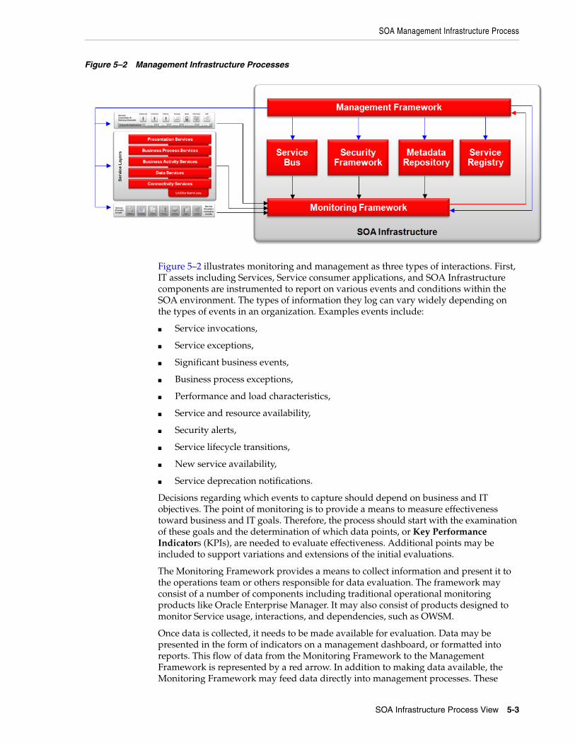
SOA Management Infrastructure Process
SOA Infrastructure Process View 5-3
Figure 5–2 Management Infrastructure Processes
Figure 5–2 illustrates monitoring and management as three types of interactions. First, IT assets including Services, Service consumer applications, and SOA Infrastructure components are instrumented to report on various events and conditions within the SOA environment. The types of information they log can vary widely depending on the types of events in an organization. Examples events include:
■ Service invocations,
■ Service exceptions,
■ Significant business events,
■ Business process exceptions,
■ Performance and load characteristics,
■ Service and resource availability,
■ Security alerts,
■ Service lifecycle transitions,
■ New service availability,
■ Service deprecation notifications.
Decisions regarding which events to capture should depend on business and IT objectives. The point of monitoring is to provide a means to measure effectiveness toward business and IT goals. Therefore, the process should start with the examination of these goals and the determination of which data points, or Key Performance Indicators (KPIs), are needed to evaluate effectiveness. Additional points may be included to support variations and extensions of the initial evaluations.
The Monitoring Framework provides a means to collect information and present it to the operations team or others responsible for data evaluation. The framework may consist of a number of components including traditional operational monitoring products like Oracle Enterprise Manager. It may also consist of products designed to monitor Service usage, interactions, and dependencies, such as OWSM.
Once data is collected, it needs to be made available for evaluation. Data may be presented in the form of indicators on a management dashboard, or formatted into reports. This flow of data from the Monitoring Framework to the Management Framework is represented by a red arrow. In addition to making data available, the Monitoring Framework may feed data directly into management processes. These

SOA Management Infrastructure Process
5-4 ORA SOA Infrastructure
processes would automatically react to events in the system and trigger management responses. This is truly the end goal in terms of SOA optimization - to continuously monitor the computing environment and adjust to events and trends in real time.
The arrows leaving the Management Framework illustrate its influences on Services, consumers, IT assets, and the SOA Infrastructure. This framework will likely be implemented as a collection of management interfaces and tools. Some interfaces will be administrative user interfaces that are purchased with other infrastructure products. OSB, OWSM, and OEM are examples of this, where service management and policy management interfaces are included with the mediation and security products. Other management interfaces may include those that accompany virtualization software, BPM tools, and rules engines. Since every environment will be unique, it is not realistic to provide specific reference architecture recommendations. Typical management concerns include:
■ Managing actual Service usage (vs. Service agreements),
■ Managing Service availability (vs. SLA commitments),
■ Managing Service dependencies (vs. dependency models),
■ Managing response time and load,
■ Managing Service versions and the routing of consumers to versions,
■ Managing security policies and access control,
■ Managing the Service lifecycle (Service candidate approvals, versions, etc.),
■ Managing transformations, routing, and mediation,
■ Managing Service discovery and taxonomy.

6
SOA Infrastructure Development View 6-1
6SOA Infrastructure Development View
This development view focuses on the actual software module organization of the software development environment as well as discussing packaging to support the planned deployment view. Design-time activities include requirements analysis, architecture analysis, system design, implementation, deployment, and provisioning. They are essentially the same activities that have been done for many years as part of the software development lifecycle, however, some have changed with the adoption of SOA.
6.1 Design-time ProcessThe software development process has been augmented for SOA to support the following activities as described in the Oracle Service Engineering Overview Practitioner Guide:
■ Service Identification: The recognition of functionality identified by a set of requirements that may constitute a Service.
■ Service Discovery: The act of locating pre-existing Services, Service candidates, or existing code that is similar to functionality needed by the current project.
■ Service Lifecycle Management: The process of tracking Services and service candidates through the development lifecycle and managing their status, progress, relationships to other Services, ownership, versions, release plan, and dependencies.
■ Service Asset Management: The act of managing assets such as contracts, schemas, usage agreements, models, requirements, etc., that are associated with a Service.
■ Service Provisioning: The set of activities required to configure infrastructure in order to make a deployed Service implementation usable in production.
In addition to these Service engineering activities, the following are also included:
■ Service Security: The configuration of infrastructure necessary to provide for security of a Service and the assets it uses.
■ Service Monitoring: The configuration of infrastructure necessary to properly monitor a Service in order to measure Key Performance Indicators (KPIs).
The design-time process unfolds over a number of environments. It generally begins with a development environment that supports the requirements analysis, architecture analysis, system design, and implementation phases of the software lifecycle. It moves on to a number of test environments designed to support functional, integration, performance, quality assurance, and various final pre-production testing. The

Design-time Process
6-2 ORA SOA Infrastructure
design-time process concludes as applications and Services are deployed into production and provisioned for use.
Figure 6–1 illustrates this progression using a simple scenario with three environments.
Figure 6–1 Design-time Progression
1. In this scenario, the development environment includes a repository, which is used to support and manage the Service lifecycle. The developers, service librarians, or persons charged with populating the repository, load Service artifacts as they are created. They may also navigate and search the repository for existing Services. By organizing requirements into related functional capabilities, and associating Service candidates and Services with the functional capabilities, it becomes possible to view a hierarchy of system functions and know which have been built as Services and which have not. It is also possible to search for functional characteristics to locate Services. As a result, the repository supports Service identification and discovery.
Services within the repository are assigned a status, such as: in-progress, available, deprecated, and retired. They are also assigned a version number so that multiple versions can coexist and be managed appropriately. The assets, such as contracts, schemas, WSDLs, usage agreements, release plans, etc., are linked together so that potential consumers of the Service can locate and download them. Through this linking, the repository supports asset management and dependency tracking.
The repository is not intended to replace traditional code management tools. As code is developed, it will continue to be managed by configuration management tools. They provide the concurrency management, release management, and build capabilities for software assets. However, code artifacts related to Services - specifically those needed by the consumer to integrate with Services, may be copied into the repository in order to make the Service discovery process easier. By grouping these assets with the Services, consumers have an easier time locating and downloading them. They also have a greater level of assurance that they are getting the correct artifacts for a particular Service and version.

Design-time Process
SOA Infrastructure Development View 6-3
Services may also be entered into a registry. The registry may act as a public facing taxonomy of Services, to be used by consumers that should not have access to the repository. It may contain enough artifacts to discover and invoke Services, and only advertise Services currently available for use. In this case the registry would only need to be deployed in a public facing environment. However, if the registry is used for runtime policy lookup or dynamic binding, then it would need to exist in the test environments as well as the production environment. Configuration additions and changes ideally would be propagated across environments using an export/import mechanism.
2. As Services are developed, it becomes necessary to establish a proxy service for mediation and loose coupling. In this scenario the Service Bus is used, and the location is shown to be within the test environment. The Service Bus, Security Framework, and Monitoring Framework could also exist in the development environment, however it would not be essential, especially if these infrastructure components seldom require development activities. It is assumed for this scenario that infrastructure is primarily configuration-driven, and therefore isn't included in the development environment.
In order to properly test the Service, a proxy service is created in the Service Bus. It routes to the Service implementation and becomes an extension of that implementation. It is here that some requirements, such as auditing, security, and interface-related (transport, protocol) requirements may be realized. Once the proxy is created, the proxy's interface becomes the Service interface. Integration between the Service Bus and implementation code becomes a communication link within the Service itself. The proxy interface and implementation interface could be exactly the same. An example would be if the proxy and Service implementation logic were both exposed as Web services. They might share the same WSDL, with the exception of the endpoint address. Regardless, the proxy interface is meant to represent the Service's interface and should be the only interface exposed to Service consumers.
The Service metadata is promoted from the development registry to the testing registry.
3. Services should specify security requirements within their Service contract. These requirements may depend on infrastructure that is designed to provide security features, e.g., the Security Framework. In order to properly test security requirements, the Security Framework has been included in the test environment. It is here that security policies are configured and tested with the Services. Policies may pertain to message-level security, following the WS-SecurityPolicy specification, or something similar. They may also pertain to entitlements, or fine-grained access control. These policies generally follow the XACML specification, or an equivalent. Security policies can be custom written for a Service, or may be reused across multiple Services with similar security requirements.
4. Services may also be assigned monitoring requirements. These requirements may be common among all Services, or all Services of a particular type; or they may be unique to a particular Service. For example, all Services may be required to log an event when they are invoked, which may include the caller's identity and a timestamp. In addition, a specific Service may be required to log an event when certain conditions occur, such as when a transaction over a certain dollar amount is performed. These requirements will need to be tested before the Service is deployed into production. The Monitoring Framework may need to be configured to read such events and process them appropriately.

Oracle Fusion SOA Development Tools
6-4 ORA SOA Infrastructure
5. Once all testing cycles have completed, the Service will need to be deployed into production and provisioned for use. The operations team is generally responsible for the production environment and production deployments. In order to ensure that the production configuration matches the final test configuration, infrastructure configuration will likely be migrated from the test environment to production, rather than manually re-entered in production. In this scenario the Service Bus, Security Framework, and Monitoring Framework configurations are exported from the test environment and imported into the production environment. The Service metadata could be automatically promoted from the test environment to the production environment. Any final configurations or code deployments will also be handled by the operations team.
OSB and OSR have the capability to synchronize with each other. This mechanism could be used to populate proxy services into the production service registry. It can also be used in the reverse direction, to populate the Service Bus from the registry. This capability may be used to propagate Services across organizational boundaries. For example, if each organization (department, portfolio, division) deploys its own infrastructure, then it may use the registry to obtain Service configuration for Services in other domains.
6. Finally, it may be necessary to adjust the Service configuration as it applies to the production environment. This may be the case when load balancing or virtualization settings need to be made or changed based on intended service level agreements. These functions are performed via the Service Management Framework. Note that this framework may consist of a number of administrative interfaces to various pieces of the SOA Infrastructure. Over time this should congeal into a more uniform framework that establishes a consistent view of the overall system.
6.2 Oracle Fusion SOA Development ToolsFigure 6–2 shows the development architecture of the Oracle Fusion SOA stack. Oracle SOA Infrastructure products are supported by development tools like Oracle JDeveloper, Eclipse, and browser based tools. JDeveloper is the strategic unified development platform for all Oracle SOA products, but for backward compatibility, Eclipse is also supported in some cases.

Oracle Fusion SOA Development Tools
SOA Infrastructure Development View 6-5
Figure 6–2 Oracle Fusion SOA Development Tools
Browser based tools are provided for development and administration related activities. It allows configuration driven development to be done using the browser. Oracle Business Process Analysis (OBPA) suite provides a component called Business Process Architect that can be used to design and model business processes. OBPM provides a designer for business process modeling and simulation.
As developers develop the SOA assets, they are placed in various repositories that include Source Code Management (SCM) systems, database repositories, and configuration repositories. For example, the OSB artifacts are stored in the database but can be exported into external configuration files.
The middle layer shows Oracle SOA infrastructure products and Service implementation platforms. The products depicted in the diagram are listed by category below.
SOA Infrastructure:
■ OER - Oracle Enterprise Repository
■ OWSM - Oracle Web Services Manager
■ OSR - Oracle Service Registry
■ OSB - Oracle Service Bus
■ OEM - Oracle Enterprise Manager
■ IdM - Oracle Identify and Access Manager
Service Platform:
■ BPEL PM - BPEL Process Manager
■ ODSI - Oracle Data Services Integrator
■ OBPM - Oracle BPM

Packaging
6-6 ORA SOA Infrastructure
■ WCS - Web Center Suite
■ OWLS - Oracle WebLogic Server
■ ODI - Oracle Data Integrator
Developers have the flexibility of choosing from a variety of migration tools to automate the promotion of assets. These range from scripting approaches like Jython or UNIX shell scripting, to preconfigured promotion workflows. There are also specific tools like Portal promotion tool or Repository Exchange Utility for promoting specific components like portal configuration or Service assets in the repository.
The Oracle Application Development Framework (Oracle ADF) is an end-to-end application framework that builds on Java Platform, Enterprise Edition (Java EE) standards and open-source technologies to simplify and accelerate implementing service-oriented applications. Oracle ADF simplifies the development of enterprise solutions that search, display, create, modify, and validate data using Web, wireless, desktop, or Web services interfaces. Used in tandem, Oracle JDeveloper and Oracle ADF give an environment that covers the full development lifecycle from design to deployment, with drag-and-drop data binding, visual UI design, and team development features built in.
6.3 PackagingPackaging of software applications for deployment purposes is an onerous task due mainly to great number of moving parts required to be synchronized to create a complete functional unit. Component based architectures, such as those supported by Java Enterprise Edition containers, now have rich tooling options to help support the packaging of a plethora of configuration files (descriptors, directories, etc.) along with the code itself (into "archive" files, JAR, WAR, EAR).
The key resources that may be modified at deployment time are:
■ Java EE Server Resources
– Clustering
– Java Message Service
– EJB Pooling and Caching
– JDBC Connection Pools
– Execution Thread Pool
– Java EE Connector Architecture
Under the approach of Service enablement, in which existing application functionality is exposed as a Service through the SOA Infrastructure capabilities (rather than new code construction), a Service is potentially deployed without complexity of traditional application deployment. This new Service Infrastructure however, brings its own complexities to the construction of deployable packages of Service capabilities.
Common types of deployable artifacts in a SOA environment generally include the following:
■ WSDL, XML Schema, XSLT, Xpath, various role definitions, WS-* docs
■ Code (in the form of JAR, WAR, EAR)
■ Directory definitions
■ Access controls
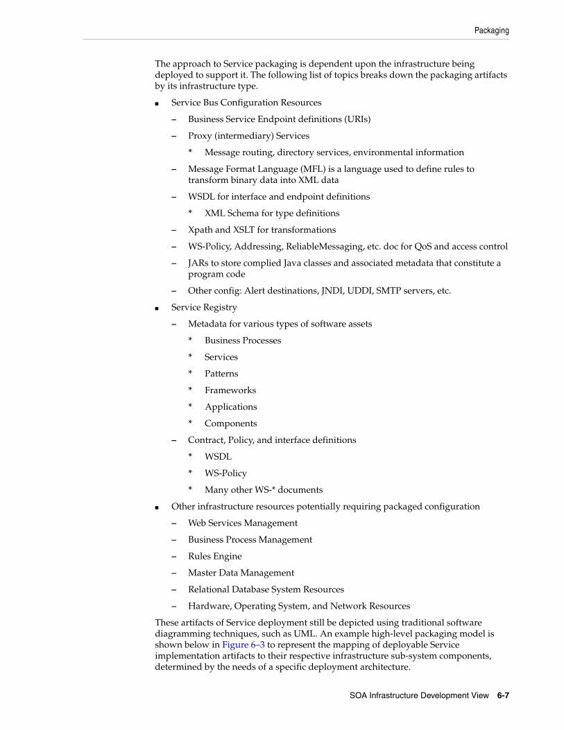
Packaging
SOA Infrastructure Development View 6-7
The approach to Service packaging is dependent upon the infrastructure being deployed to support it. The following list of topics breaks down the packaging artifacts by its infrastructure type.
■ Service Bus Configuration Resources
– Business Service Endpoint definitions (URIs)
– Proxy (intermediary) Services
* Message routing, directory services, environmental information
– Message Format Language (MFL) is a language used to define rules to transform binary data into XML data
– WSDL for interface and endpoint definitions
* XML Schema for type definitions
– Xpath and XSLT for transformations
– WS-Policy, Addressing, ReliableMessaging, etc. doc for QoS and access control
– JARs to store complied Java classes and associated metadata that constitute a program code
– Other config: Alert destinations, JNDI, UDDI, SMTP servers, etc.
■ Service Registry
– Metadata for various types of software assets
* Business Processes
* Services
* Patterns
* Frameworks
* Applications
* Components
– Contract, Policy, and interface definitions
* WSDL
* WS-Policy
* Many other WS-* documents
■ Other infrastructure resources potentially requiring packaged configuration
– Web Services Management
– Business Process Management
– Rules Engine
– Master Data Management
– Relational Database System Resources
– Hardware, Operating System, and Network Resources
These artifacts of Service deployment still be depicted using traditional software diagramming techniques, such as UML. An example high-level packaging model is shown below in Figure 6–3 to represent the mapping of deployable Service implementation artifacts to their respective infrastructure sub-system components, determined by the needs of a specific deployment architecture.

Packaging
6-8 ORA SOA Infrastructure
Figure 6–3 Example High-level Packaging Diagram
Representing packages and their infrastructure sub-systems can serve two important purposes:
■ Packages of Service implementation artifacts should be (as far as reasonably possible) self-contained to simplify the process of Service deployment
■ Traceability of packaged Service implementation facets to sub-systems in the runtime system.
Each sub-package in the high-level model below requires substantially more detail than is shown here. More detailed models can be used to show the types of artifacts that can be expected in each of the high-level sub-packages. An example of a of a more detailed package diagram is shown below in Figure 6–4.
Figure 6–4 Example Service Packaging Detail Diagram

7
Summary 7-1
7Summary
SOA Infrastructure plays a key role in accelerating adoption of SOA in an enterprise. It allows enterprises to jump-start their SOA efforts by providing most of the SOA capabilities needed to build and deploy Services. An understanding of SOA logical architecture and how it can be realized using technologies available in the market is an essential part of the SOA strategy. Oracle offers an end-to-end solution for the SOA Infrastructure requirements and this document covered various views of SOA Infrastructure and how best to leverage Oracle products to realize best in class and reliable SOA Infrastructure.
SOA Infrastructure should not be a simple installation of products; rather it should be the "realization" of the reference architecture which is aligned with the IT and business strategies. It is recommended to develop functionally driven SOA reference architecture and a multi-year SOA Infrastructure roadmap and develop the infrastructure gradually. This prudent approach to building infrastructure not only ensures that the IT investment is expended with due diligence but also reduces the risks associated with rolling out SOA in the enterprise.
This document only covered the core components of the SOA Infrastructure. Other complementary technologies, Service platform and related products are covered separately in the appropriate technology perspective documents.

7-2 ORA SOA Infrastructure
A
Further Reading A-1
AFurther Reading
The IT Strategies From Oracle series contains a number of documents that offer insight and guidance on many aspects of technology. In particular, the following documents pertaining to the SOA Infrastructure may be of interest:
A.1 Related DocumentsORA Service-Oriented Integration - The ORA Service-Oriented Integration document examines the most popular and widely used forms of integration, putting them into perspective with current trends made possible by SOA standards and technologies. It offers guidance on how to integrate systems in the Oracle Fusion environment, bringing together modern techniques and legacy assets.
ORA Security - The ORA Security document describes important aspects of security including identity, role, and entitlement management, authentication, authorization, and auditing (AAA), and transport, message, and data security.
ORA Application Infrastructure - Underpinning Oracle Fusion solutions and infrastructure is a computing platform that provides RASP qualities for enterprise-class computing. The ORA Application Infrastructure document describes these concepts and capabilities and defines the software platform on which solutions are built.
A.2 Other ResourcesIn addition, the following materials and sources of information relevant to SOA Infrastructure may be useful:
http://www.oracle.com/products/middleware/index.html - Oracle Fusion Middleware products home page.
http://download.oracle.com/docs/cd/E12839_01/index.htm - Oracle Fusion Middleware Documentation.
http://www.oracle.com/technology/products/ias/business_rules/index.html - Oracle Business Rules Documentation.
http://www.oracle.com/technetwork/middleware/weblogic/overview/index.html - Oracle WebLogic Server home page.
http://download.oracle.com/docs/cd/E13157_01/wlevs/docs30/index.html - Oracle CEP documentation.
http://download.oracle.com/docs/cd/E10316_01/ouc.htm - Oracle Univeral Content Management Documentation.

Other Resources
A-2 ORA SOA Infrastructure
http://www.oracle.com/technology/products/integration/adapters/index.html - Oracle Integration Adapters documentation.
Glossary-1
Glossary
4+1 Architectural View Model
4+1 is a view model designed by Philippe Kruchten for describing the architecture of software-intensive systems, based on the use of multiple, concurrent views. The views are used to describe the system in the viewpoint of different stakeholders, such as end-users, developers and project managers. The four views of the model are logical, development, process and physical view. In addition selected use cases or scenarios are utilized to illustrate the architecture serving as the 'plus one' view. Hence the model contains 4+1 views.
Business Process Execution Language (BPEL)
The Business Process Execution Language for Web Services (BPEL4WS or BPEL) is a formal, XML-based description language for business processes that interact via Web services.
Business Process Modeling Notation (BPMN)
BPMN is a graphical notation system for describing business processes in a business process diagram (BPD).
Usage Agreement
A Usage Agreement refers to the contract between the consumer and the SOA (infrastructure or governing body) that specifies the terms of consumption of the Service. This is different from the Provider Contract, which governs the terms between the SOA and the Service provider.
J2EE Connector Architecture (JCA)
The J2EE Connector architecture provides a Java technology solution to the problem of connectivity between the many application servers and today's enterprise information systems (EIS).
Java Messaging Service (JMS)
The Java Message Service (JMS) API is an API for accessing enterprise messaging systems. It is part of the Java 2 Platform, Enterprise Edition (J2EE).
Java Portlet Specification (JPS)
JPS is a specification that defines a set of APIs to enable interoperability between portlets and portals, addressing the areas of aggregation, personalization, presentation, and security. JPS is based on JSR 168.

JSR 168
Glossary-2
JSR 168
JSR-168 Portlet Specification standardizes how components for portal servers are to be developed.
JSR 268
JSR 268 is a next generation Java Portlet Specification that aligns the Java Portlet Specification with J2EE 1.4, other JSRs relevant for portlet programming, like JSR 188 and the next version of Web Services for Remote Portlets (WSRP).
Key Performance Indicator (KPI)
Key Performance Indicators (KPI) are measures or metrics used to help an organization define and evaluate how successful it is, in terms of making progress towards its short-term and long-term organizational goals.
Mediation
Mediation can be broadly defined as resolving the differences between two or more systems in order to integrate them seamlessly.
Message Exchange Pattern (MEP)
A Message Exchange Pattern (MEP) describes the pattern of messages required by a communications protocol to establish or use a communication channel.
Orchestration
Orchestration describes the automated arrangement, coordination, and management of Services.
Producer Contract
Producer Contract or simply the Service Contract refers to the Service contract between the provider and the SOA (infrastructure or governing body) that specifies the contract of the Service. The Producer Contract should be able to support the consolidated requirements of all the Usage Agreements for any given Service.
Service Factory
Service Factory is an efficient organizational model to build enterprise class shared services using a centralized development orgnization. The Service Factory specializes in designing and building Services at rapid pace.
Source Code Management (SCM)
Source Code Management (SCM) is the management of changes to documents, programs, and other information artifacts.
Universal Description, Discovery and Integration (UDDI)
Universal Description, Discovery and Integration (UDDI) is a platform-independent, XML based, open industry initiative, sponsored by the Organization for the Advancement of Structured Information Standards (OASIS), enabling businesses to publish service listings and discover each other and define how the services or software applications interact over the Internet.
Web Service Remote Portlet (WSRP)
WSRP is a Web services standard that enables the plug-and-play of visual, user-facing Web services with portals or other intermediary Web applications. Being a standard, WSRP enables interoperability between a standards-enabled container and any WSRP portal.

XPDL
Glossary-3
XPDL
The XML Process Definition Language (XPDL) is a format standardized by the Workflow Management Coalition (WfMC) to interchange Business Process definitions between different workflow products, ie between different modeling tools and management suites. XPDL defines an XML schema for specifying the declarative part of workflow / business process.

XPDL
Glossary-4


