92
March 2016 Oracle ® Communications Performance Intelligence Center 10.2 Feature Guide E72800 Revision 1
| Date post: | 30-Jan-2018 |
| Category: |
Documents |
| Upload: | nguyenhanh |
| View: | 239 times |
| Download: | 0 times |

March 2016
Oracle® Communications
Performance Intelligence Center 10.2
Feature Guide E72800 Revision 1

THIS DOCUMENT AND THE DATA DISCLOSED HEREIN OR HEREWITH IS PROPRIETARY AND IS NOT TO BE REPRODUCED, USED OR DISCLOSED IN WHOLE OR IN PART TO ANYONE WITHOUT THE WRITTEN PERMISSION OF ORACLE
COPYRIGHT, © ORACLE 2016
Revision: 1.0 Page 2 of 92
- Table of Contents -
1 INTRODUCING OCPIC ............................................................................................................. 6
1.1 KEY BENEFITS ......................................................................................................................... 6 1.2 ORACLE’S SOLUTION .............................................................................................................. 6
2 OCPIC PRODUCT OVERVIEW ............................................................................................... 8
2.1 DATA ACQUISITION LAYER .................................................................................................... 8 2.2 MEDIATION LAYER ............................................................................................................... 10 2.3 APPLICATIONS LAYER ........................................................................................................... 10 2.4 RELIABILITY .......................................................................................................................... 11 2.5 BACKUP CAPABILITIES .......................................................................................................... 11 2.6 MONITORED INTERFACES ..................................................................................................... 12
3 DETAILED TECHNICAL DESCRIPTION ............................................................................ 21
3.1 OCPIC MANAGEMENT .......................................................................................................... 22 3.2 OCPIC MANAGEMENT OPTIONAL APPLICATIONS................................................................ 32 3.3 OCPIC MEDIATION ............................................................................................................... 50 3.4 OCPIC MEDIATION DATA FEED ........................................................................................... 56 3.5 OCPIC DATA ACQUISITION .................................................................................................. 58 3.6 OCPIC VIRTUALIZED CONFIGURATIONS SUMMARY ............................................................ 68
4 APPENDIX A – OCPIC APPLICATION VS. OCPIC ORACLE LICENCES .................... 69
5 APPENDIX B –ACRONYMS .................................................................................................... 71
6 APPENDIX C – LIST OF SUPPORTED PROTOCOLS ....................................................... 76
THIS DOCUMENT AND THE DATA DISCLOSED HEREIN OR HEREWITH IS PROPRIETARY AND IS NOT TO BE REPRODUCED, USED OR DISCLOSED IN WHOLE OR IN PART TO ANYONE WITHOUT THE WRITTEN PERMISSION OF ORACLE
COPYRIGHT, © ORACLE 2016
Revision: 1.0 Page 3 of 92
-List of Figures -
Figure 1 – Oracle Communications Performance Intelligence Center.................................................... 7 Figure 2 - OCPIC architecture .................................................................................................................. 8 Figure 3 – OCDSR Integrated Acquisition .............................................................................................. 10 Figure 4 - PSTN monitored interfaces ................................................................................................... 12 Figure 5 - NGN and VoIP monitored interfaces .................................................................................... 13 Figure 6 - GSM/GPRS/3G monitored interfaces ................................................................................... 13 Figure 7 - CDMA monitored interfaces ................................................................................................. 16 Figure 8 - IMS monitored interfaces ..................................................................................................... 17 Figure 9 - LTE/SAE monitored interfaces .............................................................................................. 17 Figure 10 - OCPIC building blocks ......................................................................................................... 21 Figure 11 - OCPIC Management applications ....................................................................................... 22 Figure 12 - OCPIC Management applications security configuration ................................................... 24 Figure 13 - Data privacy ........................................................................................................................ 25 Figure 14 - OCPIC Management KPI application main screen .............................................................. 26 Figure 15 - OCPIC Management KPI application configuration column edition example .................... 26 Figure 16 - OCPIC Management KPI application configuration measure edition example .................. 26 Figure 17 - Example of filtering capabilities .......................................................................................... 27 Figure 18 - Possible lines definition ...................................................................................................... 27 Figure 19 - Example of alarm definition ................................................................................................ 28 Figure 20 - System alarm main screen .................................................................................................. 29 Figure 21 – Audit viewer example ........................................................................................................ 29 Figure 22 – Capacity management scope ............................................................................................. 30 Figure 23 – MAP builder configuration for anonymous SMS ............................................................... 31 Figure 24 – OCPIC Multiprotocol Troubleshooting main window for XDR, PDU and protocol ............ 31 Figure 25 - Extended filtering capability ............................................................................................... 33 Figure 26 - OCPIC XDR viewer overview ............................................................................................... 33 Figure 27 - Example OCPIC XDR viewer output .................................................................................... 34 Figure 28 - OCPIC Multiprotocol Troubleshooting screen capture ....................................................... 35 Figure 29 - Example of OCPIC Multiprotocol Troubleshooting output ................................................. 36 Figure 30 - Ladder diagram ................................................................................................................... 36 Figure 31 - Example of OCPIC Dashboard output ................................................................................. 37 Figure 32 - Example of OCPIC Network and Service Alarm output ....................................................... 38 Figure 33 - Drill-down from OCPIC Network and Service Alarm KPI Alarm to OCPIC Dashboard or to OCPIC XDR browser ............................................................................................................................... 38 Figure 34 - Table display of KPI from OCPIC Network and Service Alarm drill down ........................... 39 Figure 35 - XDR analysis and protocol decoding from OCPIC Network and Service Alarm drill down . 39 Figure 36 - Example of alarm forwarding filters ................................................................................... 40 Figure 37 - Example of alarm forwarding configuration for destination .............................................. 40 Figure 38 - Example of alarm forwarding configuration for filtering .................................................... 41 Figure 39 - OCPIC SS7 Management Architecture ................................................................................ 42 Figure 40 - Linkset view ......................................................................................................................... 43 Figure 41 – SS7 Management SIGTRAN main screen ........................................................................... 44 Figure 42 - Q.752 counters supported .................................................................................................. 47 Figure 43 - Q.752 alarm threshold ........................................................................................................ 47 Figure 44 - OCPIC Mediation ................................................................................................................. 50 Figure 45 - OCPIC Mediation subsystem overview ............................................................................... 51 Figure 46 – Data Records and Packet Data Units Storage on Customer IT sorage infrastructure ........ 53 Figure 47 - Static XDR enrichment principle ......................................................................................... 54 Figure 48 – Automatic static enrichment update ................................................................................. 55

THIS DOCUMENT AND THE DATA DISCLOSED HEREIN OR HEREWITH IS PROPRIETARY AND IS NOT TO BE REPRODUCED, USED OR DISCLOSED IN WHOLE OR IN PART TO ANYONE WITHOUT THE WRITTEN PERMISSION OF ORACLE
COPYRIGHT, © ORACLE 2016
Revision: 1.0 Page 4 of 92
Figure 49 - OCPIC Mediation Data Feed ............................................................................................... 56 Figure 50 – OCPIC Acquisition Data Feed Architecture ........................................................................ 57 Figure 51 – OCPIC Acquisition Architecture .......................................................................................... 58 Figure 52 - OCPIC Integrated Acquisition Architecture......................................................................... 59 Figure 53 - IP Raw & MSU ..................................................................................................................... 60 Figure 54 - EAGLE Frame to Integrated Acquisition connection ........................................................... 61 Figure 55: APP-B in the EAGLE frame.................................................................................................... 62 Figure 56 - Overview of OCPIC Probed Acquisition .............................................................................. 62 Figure 57 – LSL/HSL to SIGTRAN Converters ......................................................................................... 64 Figure 58 – LSL/HSL to SIGTRAN Converters – connectivity ................................................................. 64 Figure 59 – Gb over E1 to Gb over IP Converter ................................................................................... 65 Figure 60 – Pcap capture for OCPIC Probed Acquisition ...................................................................... 66 Figure 61 – OCDSR Integrated Acquisition ............................................................................................ 67 Figure 62 – OCPIC Virtualized Configurations Summary ...................................................................... 68

THIS DOCUMENT AND THE DATA DISCLOSED HEREIN OR HEREWITH IS PROPRIETARY AND IS NOT TO BE REPRODUCED, USED OR DISCLOSED IN WHOLE OR IN PART TO ANYONE WITHOUT THE WRITTEN PERMISSION OF ORACLE
COPYRIGHT, © ORACLE 2016
Revision: 1.0 Page 5 of 92
-List of Tables –
Table 1 – SMS Hiding............................................................................................................................. 30 Table 2 – SMS decoding per user’s authorization ................................................................................. 31 Table 3 – Field hiding per user’s authorization ..................................................................................... 32 Table 5 - OCPIC Probed Acquisition feature supported matrix ............................................................ 63 Table 6 – OCPIC Part Numbers and Legacy Names ............................................................................... 69 Table 7– List of acronyms ..................................................................................................................... 71 Table 8 - List of supported protocols and builders ............................................................................... 76

THIS DOCUMENT AND THE DATA DISCLOSED HEREIN OR HEREWITH IS PROPRIETARY AND IS NOT TO BE REPRODUCED, USED OR DISCLOSED IN WHOLE OR IN PART TO ANYONE WITHOUT THE WRITTEN PERMISSION OF ORACLE
COPYRIGHT, © ORACLE 2016
Revision: 1.0 Page 6 of 92
1 INTRODUCING OCPIC
1.1 KEY BENEFITS
In a tough competive landscape CSPs need to implement new technologies while optimizing their cost. LTE is in their radar screen since a while now, but it is deployed based on economical and regulatory drivers and requires still a lot of efforts. Frequently LTE coverage is partial and it is needed to rely still on 3G when not 2G. Therefore network complexity is growing while price pressure is higher than ever.
In order to drive securely their daily tasks and make the right decisions CSPs need to thoroughly oversee their core network, with flexible tools delivering visibility and allowing to smoothly transition services from 3G/2G to LTE.
With no doubts there is a high value in the data that CSPs are managing and signaling can be monetized. From that point of view, a monitoring solution that can flexibly feed external application becomes a new applications enabler and helps to generate revenue differently than from traditional subscriptions.
1.2 ORACLE’S SOLUTION
Oracle Communications Performance Intelligence Center (OCPIC) is a comprehensive suite of applications, which provides an in-depth understanding of the network and equips wireline and wireless CSPs with the tools required to make informed business investment and cost reduction decisions.
OCPIC provides a set of tools needed to capture network traffic data and convert it into useful business intelligence for troubleshooting, managing traffic, services and QoS metrics in a flexible manner.
OCPIC provides reliable real-time or historic information based on the most important source of service provider revenue – network signaling traffic. OCPIC collects signaling data extracted from the network using carrier-grade platforms dedicated to this purpose. This data is correlated and processed to provide network, service, and subscriber information -- information that is critical to optimize revenue, increase profitability, reduce churn, deploy new services, and manage network migration.
OCPIC is designed to meet the needs of many functions within the CSP’s organization, including network operations, customer care, troubleshooting, roaming, marketing, revenue assurance, fraud, finance, business development, and security.
OCPIC is network equipment vendor independent and can be deployed basically on any type of network, (GSM, CDMA, 3G /LTE/EPC, fixed) regardless of the core network vendor. OCPIC is a non-intrusive monitoring system, and as such does not use any resources from network elements.
Service providers use OCPIC to manage interconnection agreements, increase roaming revenue, ensure end-to-end QoS across the network, detect fraud, analyze subscriber behavior, and examine service usage. Moreover OCPIC is of great help in supporting existing applications such as fraud management, interconnect accounting, or assessing service level agreements with key interconnect partners or high value accounts. Support of above services is being provided in a seamless manner across customer’s wireline VoIP networks and wireless LTE, IMS and 3G facilities.

THIS DOCUMENT AND THE DATA DISCLOSED HEREIN OR HEREWITH IS PROPRIETARY AND IS NOT TO BE REPRODUCED, USED OR DISCLOSED IN WHOLE OR IN PART TO ANYONE WITHOUT THE WRITTEN PERMISSION OF ORACLE
COPYRIGHT, © ORACLE 2016
Revision: 1.0 Page 7 of 92
The OCPIC set of applications helps leverage raw network traffic data into business/service-oriented triggers such as key performance indicators (KPIs), trends, alarms and statistics. The OCPIC platform is built using open interfaces and a Web-based graphical user interface, ensuring ease of use.
OCPIC features extended integration with the EAGLE, offering an industry unique feature , made of a carrier grade probeless signaling data acquisition module. OCPIC can also be deployed as a standalone solution with probes, or even in a mixed mode , which reduces operational expenses and allows CSPs to scale more quickly.
The OCPIC platform supports major industry protocols such as,
SS7/SIGTRAN (ISUP, MAP, IS41, INAP, CAP…),
VoIP/NGN (SIP, H.323, H.248, MGCP…),
GPRS (Gn, Gi, Gb…) UMTS (IuPS, IuCS)
SAE/LTE and Diameter (Diameter interfaces , GTPv2, S1C…).
Figure 1 – Oracle Communications Performance Intelligence Center
Focused on performance management, OCPIC provides applications to address troubleshooting, surveillance, and the creation of key performance indicators (KPIs).

THIS DOCUMENT AND THE DATA DISCLOSED HEREIN OR HEREWITH IS PROPRIETARY AND IS NOT TO BE REPRODUCED, USED OR DISCLOSED IN WHOLE OR IN PART TO ANYONE WITHOUT THE WRITTEN PERMISSION OF ORACLE
COPYRIGHT, © ORACLE 2016
Revision: 1.0 Page 8 of 92
2 OCPIC PRODUCT OVERVIEW
The architecture has 3 building blocks: Data acquisition and collection, mediation and applications. Data acquisition can be deployed into the service providers network using signaling interconnect points. The correlation and storage and applications platform are a powerful application processing engine enabling the user to derive “visibility” into traffic transiting their network.
Figure 2 - OCPIC architecture
*Due to rebranding the applications and system elements have been renamed. Please refer to Appendix A – OCPIC APPLICATION VS. OCPIC ORACLE LICENCES for the correspondence.
2.1 DATA ACQUISITION LAYER
It is this layer of the architecture that collects the signaling data from across a network. Equipment is deployed that adapts to the customer network physical interface.
The main functions at this layer are:
Network adaptation
Frame capture
Frame time stamping
Frame filtering
Frame routing
Two types of data acquisition is supported with OCPIC: probeless meaning integrated with Core Service nodes as EAGLE, and stand-alone.
2.1.1 Integrated Acquisition
The OCPIC Integrated Acquisition receives the messages and events from the EAGLE and serves as a local processor for the acquisition and short term buffering of collected traffic. The OCPIC Integrated Acquisition provides reliable connectivity to all links supported on the EAGLE. Through the interface between the Eagle and the OCPIC Integrated Acquisition server, the Eagle configuration information is communicated to OCPIC system for simplified provisioning.

THIS DOCUMENT AND THE DATA DISCLOSED HEREIN OR HEREWITH IS PROPRIETARY AND IS NOT TO BE REPRODUCED, USED OR DISCLOSED IN WHOLE OR IN PART TO ANYONE WITHOUT THE WRITTEN PERMISSION OF ORACLE
COPYRIGHT, © ORACLE 2016
Revision: 1.0 Page 9 of 92
2.1.2 Stand-alone Acquisition
Stand-alone Acquisition does support data capture at networks not currently using EAGLE nodes, to capture at IP acquisition points. It requires a passive (non intrusive) probe and is being used to monitor IP based traffic including SIGTRAN, GPRS/UMTS/LTE traffic , Gb interface as well as Iu over IP.
For Ethernet, OCPIC Probed Acquisition supports 4x 1GE ports or 4x 10GE ports. All ports are SFP+ compatible. SFP modules are available for 1000 BASE-T Ethernet, 1000 BASE-SX, 1000BASE-LX, 10G BASE-SR, and 10G BASE-LR.
Stand-alone acquisition is compatible with TAPs and port mirroring.
T1/E1 legacy SS7 links are available through a SIGTRAN converter and Gb over E1 through GboIP converter.
2.1.3 OCDSR Integrated Acquisition
Oracle Communications Diameter Signaling Router (OCDSR) is a comprehensive platform that centralizes routing, traffic management and load balancing, creating an architecture that enables IMS and LTE networks to grow incrementally to support increasing service and traffic demands. OCPIC features a Diameter monitoring solution integrated to OCDSR. This integrated solution provides compelling advantages as:
It presents automatic link configuration of OCPIC thanks to configuration automatically forwarded by OCDSR to OCPIC management and configuration application, avoiding time consuming manual configuration in OCPIC.
It provides enriched data records, on top of the host name (e.g. HSS) captured from the signaling. It enables enhanced troubleshooting with peer node name details showing up in Multi-protocol Troubleshooting application.
OCDSR Integrated Acquisition is based on standalone Acquisition probe as described in §2.1.2.
This configuration is fully dedicated to OCDSR monitoring and only OCDSR Diameter traffic can be monitored by OCDSR Integrated Acquisition probe.

THIS DOCUMENT AND THE DATA DISCLOSED HEREIN OR HEREWITH IS PROPRIETARY AND IS NOT TO BE REPRODUCED, USED OR DISCLOSED IN WHOLE OR IN PART TO ANYONE WITHOUT THE WRITTEN PERMISSION OF ORACLE
COPYRIGHT, © ORACLE 2016
Revision: 1.0 Page 10 of 92
MME MME MME
OCDSR
Retrieve SCTP/TCP link
IP/node name association
from OC DSR
(e.g. HSS FE)
• OCPIC data record captures source and destination node names, from OCDSR configuration tables,
• Feature deliver enriched data records, on top of the host name (e.g. HSS) captured from the signaling.
• Enables enhanced troubleshooting with peer node name details showing up in Multi-protocol Troubleshooting Application
• Better network performance with e.g. KPIsproviding insight to OCDSR enforcedloadsharing.
OCPIC
Benefits:
• Troubleshooting made easier
• Peer node identification in OCPIC Browser/ Troubleshooting tool
• KPIs supporting peergranularity
HSS
HSS
FE
HSS HSS HSS
HSS
FE
HSS
FE
HSS
FE
HSS
FE
HSS
FEHSS
FE
HSS
FE
Figure 3 – OCDSR Integrated Acquisition
2.2 MEDIATION LAYER
The correlation and storage subsystem contains a library of signaling XDR protocol builders which correlate in real time signaling messages into XDR depending on protocol. Key performance indicators (KPI) can be defined by the user and are then processed in this portion of the system. These KPI are then provided to the customer in reports and alarms that can be triggered based on thresholds. OCPIC Mediation also manages the storage of raw PDU, XDR and KPI.
For data retention, the XDR storage can support up to 365 days and PDU storage duration is up to 100 days to insure long-term troubleshooting and call analysis. As far as KPI storage is concerned, duration goes up to 2 years, for extended analysis.
It is also possible as an option on a per mediation site basis to store xDR and/or PDU on Customer IT Storage Infrastructure (Cloud). In that case, limits in xDR/PDU/KPI storage duration is only limited by the storage space allocated by the Customer.
Unlike OCPIC internal storage whose access is strictly limited to OCPIC Users and Applications, Databases in Customer IT Storage Infrastructure can be queried by non OCPIC Users and Applications according to access and processing resources allocated by the Customer.
2.3 APPLICATIONS LAYER
OCPIC has a variety of applications which can be combined together for a single point system with multiple business solutions. The cornerstone element is OCPIC Management which enables users to access applications with a web browser interface. In addition, OCPIC system maintenance and data resources are centralized for simplified administration.
THIS DOCUMENT AND THE DATA DISCLOSED HEREIN OR HEREWITH IS PROPRIETARY AND IS NOT TO BE REPRODUCED, USED OR DISCLOSED IN WHOLE OR IN PART TO ANYONE WITHOUT THE WRITTEN PERMISSION OF ORACLE
COPYRIGHT, © ORACLE 2016
Revision: 1.0 Page 11 of 92
A basic system would consist of:
Centralized configuration management to configure the OCPIC system
Security application to configure users and profiles to control access to applications and data
OCPIC Multiprotocol Troubleshooting as OCPIC XDR viewer: Single/multi protocol and single/multi session filtering and decode
OCPIC Management KPI application: Open KPI generation for ultimate visibility into traffic and resources
Self-surveillance applications by means of system alarming.
The other applications listed below are optional applications:
OCPIC SS7 Management: Near real-time SS7 and SIGTRAN network monitoring with stats and state information
OCPIC Multiprotocol Troubleshooting call tracer: multi-protocol, multi-network message trace and decode
OCPIC Network and Service Alarm: alarm definition and reporting for OCPIC and network
OCPIC Network and Service Alarm forward: send alarms to external fault management platform or email addresses
OCPIC Dashboard: graphical display of KPIs; dashboard creation for output of the OCPIC Management KPI application
Data Export
Generic export modules used to export XDR/KPI records via NFS or Oracle.
2.4 RELIABILITY
The OCPIC is architected in such a way that if OCPIC Management fails, it will not impact the function of the acquisition and mediation layers of the system. Each component of acquisition and mediation layer has its own configuration data replicated locally from the master database.
Events that were being managed by the failed instance will be re-processed when the instance restarts. However, events being processed by the failed instance will be discarded if the alarm has been terminated otherwise they will be managed by the failed instance when it re-starts.
For the OCPIC Mediation, optional redundancy mechanisms with automatic server failover are provided. This will assure no loss of insertion data in the case of server failure
2.5 BACKUP CAPABILITIES
The OCPIC management provides the ability to backup the following:
All configuration data for OCPIC Integrated or stand-alone Acquisition and OCPIC Mediation
All configuration and network topology data associated with all applications
Application configuration data (OCPIC Dashboard, OCPIC network and service alarm
The database backup is performed on the OCPIC Management storage array. This backup is scheduled on a daily basis. The last 7 backups are maintained for restore possibility.
There is no XDR/PDU backup/restore. Only alternative is to use export to an external Oracle data warehouse. Backup restore is, in this case under the responsibility of the customer. OCPIC XDR

THIS DOCUMENT AND THE DATA DISCLOSED HEREIN OR HEREWITH IS PROPRIETARY AND IS NOT TO BE REPRODUCED, USED OR DISCLOSED IN WHOLE OR IN PART TO ANYONE WITHOUT THE WRITTEN PERMISSION OF ORACLE
COPYRIGHT, © ORACLE 2016
Revision: 1.0 Page 12 of 92
Viewer can be used on top of Oracle Data warehouse. Only XDR and KPI are concerned, no PDU can be backed up by this workaround solution
2.6 MONITORED INTERFACES
OCPIC supports a very broad array of protocols. OCPIC is protocol agnostic. It covers the needs for carriers operating networks that are wireless (CDMA/TDMA, GSM, LTE/EPS), wire line, circuit, or packet based, or a combination of these. Adding new protocols to be supported is accomplished through the addition of protocol builders via a plug-in to cover the new interfaces to monitor, and to adapt platform HW size to process and store added traffic .
This enables the following situations to be handled:
Monitoring of a CSP's entire SS7 network
Monitoring on both SS7 and SIP sides of a VoIP gateway used for interconnection with a long-distance VoIP carrier
Monitoring 2G, 3G and 4G network signaling
The advantages of this architecture are:
A single system
Same IP probe as for the widely-deployed SS7, GPRS, UMTS, LTE & VoIP solutions
No specific training required for IP: the same applications as for SS7 are used
Ability to easily set traffic statistics & QoS indicators whatever the protocol on the interconnection
The following sections will go through the network collection points available on OCPIC. For a complete list of supported protocols please see Appendix B List of Protocols.
2.6.1 PSTN Networks
For the TDM world the key protocols supported are the following:
Figure 4 - PSTN monitored interfaces
PIC observed interfaces
THIS DOCUMENT AND THE DATA DISCLOSED HEREIN OR HEREWITH IS PROPRIETARY AND IS NOT TO BE REPRODUCED, USED OR DISCLOSED IN WHOLE OR IN PART TO ANYONE WITHOUT THE WRITTEN PERMISSION OF ORACLE
COPYRIGHT, © ORACLE 2016
Revision: 1.0 Page 13 of 92
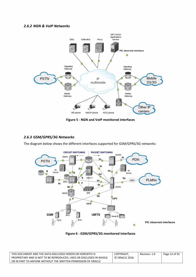
2.6.2 NGN & VoIP Networks
Figure 5 - NGN and VoIP monitored interfaces
2.6.3 GSM/GPRS/3G Networks
The diagram below shows the different interfaces supported for GSM/GPRS/3G networks:
Figure 6 - GSM/GPRS/3G monitored interfaces
PIC observed interfaces
PIC observed interfaces

THIS DOCUMENT AND THE DATA DISCLOSED HEREIN OR HEREWITH IS PROPRIETARY AND IS NOT TO BE REPRODUCED, USED OR DISCLOSED IN WHOLE OR IN PART TO ANYONE WITHOUT THE WRITTEN PERMISSION OF ORACLE
COPYRIGHT, © ORACLE 2016
Revision: 1.0 Page 14 of 92
This section presents the benefits of monitoring the interfaces supported by OCPIC.
A interface
Degradation can be noticed by subscribers due to mobility, handover, localization and radio problems (for example). Some air interface problems are also easily detected without a need to install probes at all the numerous Abis interfaces.
This interface also carries SMS & USSD information.
B interface
This interface is used to analyze efficiency of VLR management of subscriber mobility.
C interface
This interface is used to analyze efficiency of HLR management of subscriber mobility.
D interface
This interface is used to analyze efficiency of HLR management of subscriber mobility.
E interface
This interface is used to analyze SMS and handover efficiency when a user moves from one MSC to another.
F interface
Handset identification efficiency analysis can be monitored at this interface.
G interface
Location area update procedures data exchanged between VLRs are monitored when using standard MAP protocol.
J interface
Efficiency on user services exchanged between SCP and HLR can be performed at this interface.
Mc interface
Mc is of great interest to be monitored as it gathers information on RAN 2G and 3G interfaces with core network in addition to protocol between MSC server and MGW. Protocols encountered here are BSSAP, RANAP, H.248, Q.931/IUA.
Nc interface
On this interface we will find typically BICC, SIPT/I protocol managing calls between MGWs in the network.
Gb Interface
It provides information on:
Data transport network availability
Routing and QoS: circuit management, paging, radio status, flow control, flush LL, LLC discard…
Mobility management efficiency: attach, detach, RA update, PTMSI reallocation, authentication/ciphering…
Session management efficiency: activation, deactivation, modify PDP context, SMS…
THIS DOCUMENT AND THE DATA DISCLOSED HEREIN OR HEREWITH IS PROPRIETARY AND IS NOT TO BE REPRODUCED, USED OR DISCLOSED IN WHOLE OR IN PART TO ANYONE WITHOUT THE WRITTEN PERMISSION OF ORACLE
COPYRIGHT, © ORACLE 2016
Revision: 1.0 Page 15 of 92
Iu-PS and Iu-CS interfaces over IP
It enables observation of the following information:
RNC relocation, RAB management, paging, security…
Call control – call setup, release…
Mobility management – attach, detach, RA update, LA update…
Session management – PDP context activation, deactivation…..
SMS traffic efficiency
USSD traffic efficiency
Gn interface
GPRS/UMTS PDP Context management and related QoS
Gp interface
The Gp interface presents the data flow and session management interface with other PLMNs for data roaming in and out.
The same analysis as the one carried out on the Gn interface can be performed.
Gi interface
Radius protocol traffic for authorization and authentication and DHCP for IP address allocation can be observed on Gi interface.
Gr interface (GPRS/UMTS)
This interface allows ciphering parameters capture to decode ciphered Gb and also monitoring of major procedures such as location update, authentication….
Gs interface (GPRS/UMTS)
Gs interface can be used in some cases for efficiency management of the location information and paging related to mobiles that are attached to both GPRS and GSM circuit networks.
Gd interface (GPRS/MAP)
Interface allowing SMS traffic QoS measurement.
Gf interface (GPRS/UMTS)
Interface for handset authentication efficiency measurement.
Gy interface (GPRS/UMTS)
Credit control interface between GGSN and OCS. Enables to control and to trace requested, granted and used service units.
IN/CAMEL interface (GSM/GPRS/UMTS)
Interface for IN server efficiency management (essentially for prepaid and hot billing monitoring)

THIS DOCUMENT AND THE DATA DISCLOSED HEREIN OR HEREWITH IS PROPRIETARY AND IS NOT TO BE REPRODUCED, USED OR DISCLOSED IN WHOLE OR IN PART TO ANYONE WITHOUT THE WRITTEN PERMISSION OF ORACLE
COPYRIGHT, © ORACLE 2016
Revision: 1.0 Page 16 of 92
2.6.4 CDMA Networks
The diagram below shows the different interfaces supported for CDMA networks:
Figure 7 - CDMA monitored interfaces
PIC observed interfaces
THIS DOCUMENT AND THE DATA DISCLOSED HEREIN OR HEREWITH IS PROPRIETARY AND IS NOT TO BE REPRODUCED, USED OR DISCLOSED IN WHOLE OR IN PART TO ANYONE WITHOUT THE WRITTEN PERMISSION OF ORACLE
COPYRIGHT, © ORACLE 2016
Revision: 1.0 Page 17 of 92
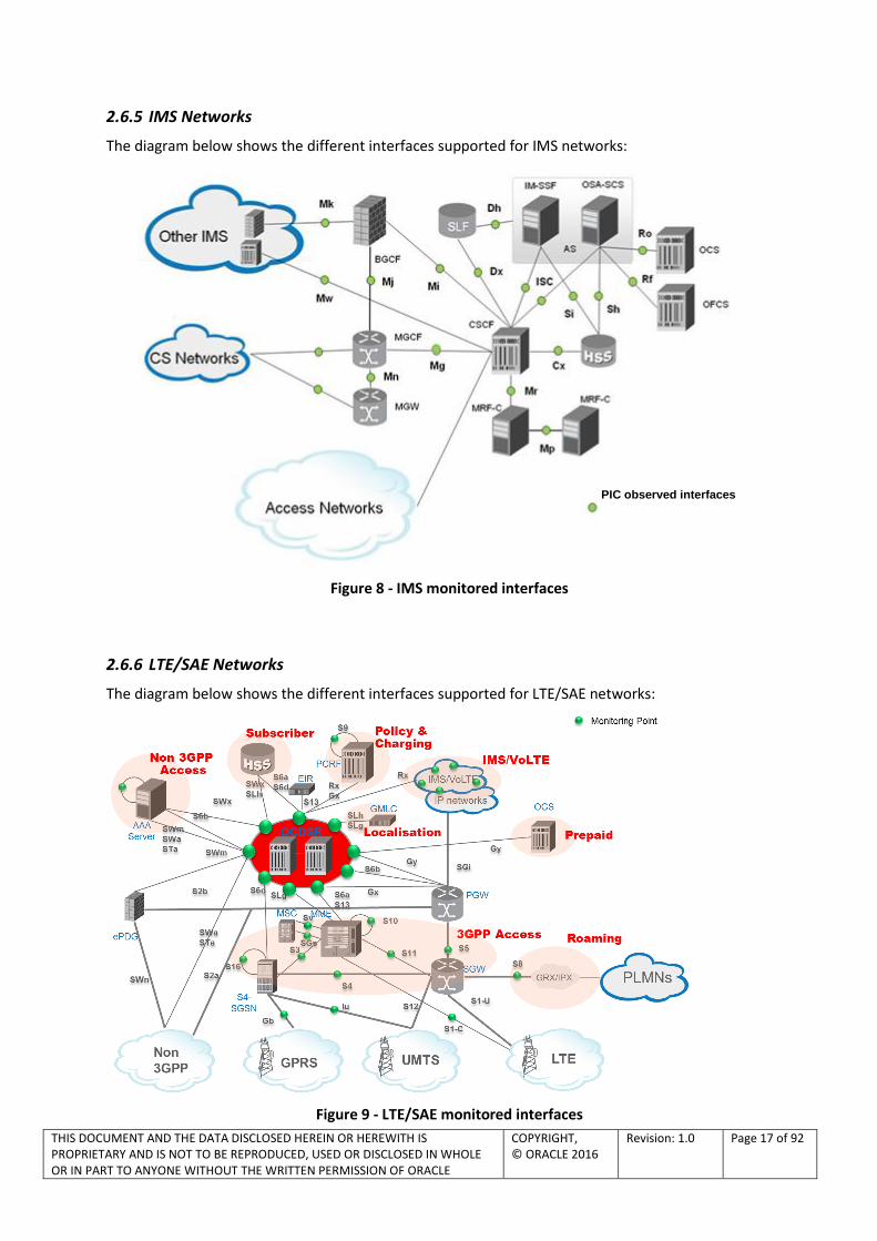
2.6.5 IMS Networks
The diagram below shows the different interfaces supported for IMS networks:
Figure 8 - IMS monitored interfaces
2.6.6 LTE/SAE Networks
The diagram below shows the different interfaces supported for LTE/SAE networks:
Figure 9 - LTE/SAE monitored interfaces
PIC observed interfaces

THIS DOCUMENT AND THE DATA DISCLOSED HEREIN OR HEREWITH IS PROPRIETARY AND IS NOT TO BE REPRODUCED, USED OR DISCLOSED IN WHOLE OR IN PART TO ANYONE WITHOUT THE WRITTEN PERMISSION OF ORACLE
COPYRIGHT, © ORACLE 2016
Revision: 1.0 Page 18 of 92
3GPP ACCESS
S1-C interface non cyphered interface S1-C is a RAN fundamental interface for monitoring as it provides information on:
- Inter MME handover - ERAB (establishment, modification, release) - NAS EMM: mobility management (attach, detach, tracking area update, service request) - NAS ESM: default/dedicated bearer context activation, modification, deactivation; PDN
connect/disconnect request by UE, UE requested bearer resource allocation/modification GTPv2 C – Tunnel management (S4, S11, S5, S8 interfaces) GTPv2C tunnel management is dedicated to mainly:
- PDN sessions-default bearer management (create/modify/delete session) - Dedicated bearer management (create, update, delete) - UE initiated activate/deactivate bearer resource command -
GTPv2 C – Mobility Management (S3, S10, S16 interfaces) GTPv2C is dedicated to mainly:
- Forward relocation (handover, relocation, SRVCC) - MM/EPS bearers context transfer - UE identification transfer - MME/SGSN detach coordination
Among others, monitoring this interface enables to trace all the traffic of a mobile including inter-technology handover, which is very frequent in mobile 4G network and is a big potential source of QoE (Quality of Experience) degradation.
SGs interface SGs is a critical interface enabling an LTE mobile to setup/receive a call through CSFB (Circuit Switched Fallback) mechanism by the time VoLTE is used by the network. Sv interface Sv is a key interface in VoLTE between MME and MSS assuring inter-RAT handover within the critical SRVCC procedure (Single Radio Voice Call Continuity) during an established call. Sv interface monitoring enables to get a full overview of PS to CS and CS to PS handover and IMS session transfer requested further to an SRVCC procedure.
SUBSCRIBER
S6 interface S6 interface provides information on:
- Location management (update/cancel location) - Subscriber data - Authentication
S13 interface S13 interface is used for tracking stolen handsets

THIS DOCUMENT AND THE DATA DISCLOSED HEREIN OR HEREWITH IS PROPRIETARY AND IS NOT TO BE REPRODUCED, USED OR DISCLOSED IN WHOLE OR IN PART TO ANYONE WITHOUT THE WRITTEN PERMISSION OF ORACLE
COPYRIGHT, © ORACLE 2016
Revision: 1.0 Page 19 of 92
POLICY AND CHARGING
Gy interface
Credit Control interface between GGSN/PGW and OCS. Enables to control and to trace efficiency of request, granted and used service units. Monitoring this interface provides useful information about credit control process in a multi-service environment.
Gx interface Gx interface between GGSN/PGW and PCRF is a key interface for flow based charging. Monitoring Gx provides information on the following processes:
- PGW requests PCC rules from PCRF - PCRF forwards a PCC rule to PGW - PGW forwards events to PCRF (e.g. RAT change, end of subscriber credit…)
Rx interface Rx interface supports the QoS and media resources reservation/modification in VoLTE from IMS network to access network.
ROAMING
S8 interface S8 interface transports user data in roaming in/out situation. S8-C provides QoS information on PDN session management (create/modify/delete session) and dedicated bearer management (create, update, delete) for roaming IN and OUT. S9 interface
This interface is the companion interface of Gx interface, supporting monitoring of business sensitive roaming traffic . This interface is required to exchange policy and charging information in roaming situation, between 2 CSPs. Monitoring this interface delivers added value to service providers in that it enables to trace policy and charging information exchanged between the visited network and the home network.
LOCATION SERVICE
SLg and SLh interfaces Monitoring GMLC (Gateway Mobile Location Center) server interface: SLg between MME and GMLC and SLh between GMLC and HSS/HLR.

THIS DOCUMENT AND THE DATA DISCLOSED HEREIN OR HEREWITH IS PROPRIETARY AND IS NOT TO BE REPRODUCED, USED OR DISCLOSED IN WHOLE OR IN PART TO ANYONE WITHOUT THE WRITTEN PERMISSION OF ORACLE
COPYRIGHT, © ORACLE 2016
Revision: 1.0 Page 20 of 92
NON 3GPP ACCESS
Monitoring AAA server
AAA server is a key service node to deliver access to 3GPP network from WiFi including VoWiFi with the following interfaces relevant for monitoring:
SWa (untrusted) : mobile authentication & authorization
STa (trusted) : mobile authentication & authorization
SWm (untrusted): tunnel authentication and authorization.
SWx : Mobile authentication & authorization through HSS
S6b: PGW address information to AAA server
THIS DOCUMENT AND THE DATA DISCLOSED HEREIN OR HEREWITH IS PROPRIETARY AND IS NOT TO BE REPRODUCED, USED OR DISCLOSED IN WHOLE OR IN PART TO ANYONE WITHOUT THE WRITTEN PERMISSION OF ORACLE
COPYRIGHT, © ORACLE 2016
Revision: 1.0 Page 21 of 92
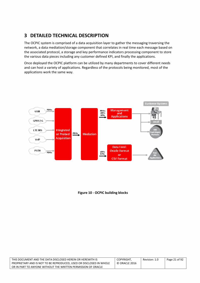
3 DETAILED TECHNICAL DESCRIPTION
The OCPIC system is comprised of a data acquisition layer to gather the messaging traversing the network, a data mediation/storage component that correlates in real time each message based on the associated protocol, a storage and key performance indicators processing component to store the various data pieces including any customer defined KPI, and finally the applications.
Once deployed the OCPIC platform can be utilized by many departments to cover different needs and can host a variety of applications. Regardless of the protocols being monitored, most of the applications work the same way.
Figure 10 - OCPIC building blocks

THIS DOCUMENT AND THE DATA DISCLOSED HEREIN OR HEREWITH IS PROPRIETARY AND IS NOT TO BE REPRODUCED, USED OR DISCLOSED IN WHOLE OR IN PART TO ANYONE WITHOUT THE WRITTEN PERMISSION OF ORACLE
COPYRIGHT, © ORACLE 2016
Revision: 1.0 Page 22 of 92
3.1 OCPIC MANAGEMENT
Figure 11 - OCPIC Management applications
3.1.1 OCPIC Management framework
Today's enterprises gain competitive advantage by quickly deploying applications that provide unique business services. Business applications must scale complete 24 x 7, enterprise-wide services, accessible by a number of clients simultaneously.
3.1.1.1 OVERVIEW
OCPIC Management forms the core of a wide range of applications offered by Oracle.
OCPIC Management manages the configuration of a OCPIC system. This allows a centralized configuration and does not need to be entered in multiple locations.
NTP provides system time synchronization between all elements of OCPIC. OCPIC Management supports NTP synchronization from external NTP server.
3.1.1.2 MAJOR BENEFITS
Web-based GUIs (Graphical User Interfaces)
No installation on client workstation
Anyone with access privileges can access the applications via URL
Highly scalable
. Trace
. Dashboard
. Network and Service Alarm
. SS7 Network Surveillance

THIS DOCUMENT AND THE DATA DISCLOSED HEREIN OR HEREWITH IS PROPRIETARY AND IS NOT TO BE REPRODUCED, USED OR DISCLOSED IN WHOLE OR IN PART TO ANYONE WITHOUT THE WRITTEN PERMISSION OF ORACLE
COPYRIGHT, © ORACLE 2016
Revision: 1.0 Page 23 of 92
Reduced cost of maintenance
Centralized configuration
Consistency guaranteed across the applications as they all utilize the same source for their data
Import configuration using csv files
All elements and applications look to OCPIC Management for their configuration, i.e. the data acquisition layer and the mediation layer.
Reduced time and cost of deployment
Easily administered (central administration and monitoring)
OCPIC provides a set of system alarms that can be viewed by the user in the system alarm tool that is provided as part of the base OCPIC Management.
OCPIC system self-surveillance is provided via system alarm management application.
Secured and highly configurable access to features and data
Authentication: verification of users’ identities
Authorization: access control to resources and applications
Confidentiality: privacy to protect sensitive data
OCPIC Management Server can also be virtualized, using VMware or KVM hypervisor (see section 3.6).
3.1.2 OCPIC Management Base Configuration Features
3.1.2.1 CENTRALIZED CONFIGURATION
The centralized configuration application is used to configure the OCPIC system. From a single location you can configure the complete system in a very efficient way. The configuration application manages a central database containing all configuration information. Configuration information can be separated in two parts:
data that all applications can utilize like the network topology
configuration dedicated for frames flows to XDR generation and storage.
The central database avoids unnecessary duplication of the configuration. The data consistency is guaranteed by the use of one single data model in one place
The configuration data is stored in an Oracle database with all standard features associated to standard database: export, backup, etc.
OCPIC EAGLE & OCDSR Integrated Acquisition, OCPIC Probed Acquisition and OCPIC Mediation synch-up from the central database simplifying the data recovery and upgrades.
The central configuration is integrated with the OCPIC Management platform. It has a web based graphical user interface and provides a strong security layer while access to the configuration is simplified.

THIS DOCUMENT AND THE DATA DISCLOSED HEREIN OR HEREWITH IS PROPRIETARY AND IS NOT TO BE REPRODUCED, USED OR DISCLOSED IN WHOLE OR IN PART TO ANYONE WITHOUT THE WRITTEN PERMISSION OF ORACLE
COPYRIGHT, © ORACLE 2016
Revision: 1.0 Page 24 of 92
Using a browsing tree on the left pane in addition to perspectives for different aspects of the configuration task makes it easy to configure the OCPIC system.
The central configuration supports the import of configuration data using csv files.
The configuration consists in defining the PDU or IP frame filtering and routing from the acquisition to the correlation function of the mediation layer up to the storage.
It is also the definition of network views which allow the monitored network to be zoned logically. It can be based on geographical locations, partners, customers, etc. They are used by next-generation applications like the web-based OCPIC Multiprotocol Troubleshooting. They support hierarchy. That is, a network view can contain other network views
The user can create Network Views for:
Sessions: grouping of multi-protocol XDR sessions
Links: grouping of links ( e.g. SS7 linksets or Gb links)
3.1.2.2 SECURITY
OCPIC Management offers a highly configurable security policy to ensure that data and applications are accessed only by the users that have access privileges. The security application is there to configure the user’s profiles. A profile is a convenient way to assign roles to users. Roles are divided in two categories:
Feature access roles to control access to features (fixed and cannot be changed)
Privacy roles to control access to data (roles can be added to match any organization)
Figure 12 - OCPIC Management applications security configuration

THIS DOCUMENT AND THE DATA DISCLOSED HEREIN OR HEREWITH IS PROPRIETARY AND IS NOT TO BE REPRODUCED, USED OR DISCLOSED IN WHOLE OR IN PART TO ANYONE WITHOUT THE WRITTEN PERMISSION OF ORACLE
COPYRIGHT, © ORACLE 2016
Revision: 1.0 Page 25 of 92
A subset of data can be protected from public access by defining a privacy role for that subset. Then, only users granted with that privacy role will be allowed to see the data. This applies to sessions containing XDRs, dashboards, queries, maps, etc. Those objects can be shared using “rwx” rights. R means that the object can be listed. X means that the object can be viewed. W means that configuration of the object can be changed.
The picture below shows an example of sharing a dashboard to different privacy roles.
Figure 13 - Data privacy
The security application allows an OCPIC Management administrator to set the security policy for password management. This includes but is not limited to: password length and strength, password aging …
In addition, this application provides the verification of the number of users simultaneously logged into the system. The number of tokens is positioned based on the quote. If 10 simultaneous users were bought, 10 tokens will be available. The platform will check each time a user logs in or logs out to maintain the pool of tokens. This is the platform that handles this, for the benefit of all the applications.
3.1.2.3 KPI & ALARM CONFIGURATION
Defining real-time alarms on any traffic conditions, setting thresholds and implementing KPIs (Key Performance Indicators) and KQIs (Key Quality Indicators) are critical elements to be taken to monitor networks efficiently.
With OCPIC Management KPI application, you can define specific KPIs/KQIs and alarm to be generated for a given traffic flow. Post-processing treatment will help manage alarm-related information for a given time interval over a specific period for maintenance purposes and troubleshooting.

THIS DOCUMENT AND THE DATA DISCLOSED HEREIN OR HEREWITH IS PROPRIETARY AND IS NOT TO BE REPRODUCED, USED OR DISCLOSED IN WHOLE OR IN PART TO ANYONE WITHOUT THE WRITTEN PERMISSION OF ORACLE
COPYRIGHT, © ORACLE 2016
Revision: 1.0 Page 26 of 92
Figure 14 - OCPIC Management KPI application main screen
OCPIC Management KPI application configurations are matrix where you can filter traffic you want to calculate statistics on.
Columns are used to calculate indicators like ASR, NER or anything you need. Rows are typically used to segregate traffic for countries, regions, equipment…
Figure 15 - OCPIC Management KPI application configuration column edition example
An addition, useful feature makes it possible to use a task scheduler based on predefined thresholds in order to enable alarm monitoring for specific periods e.g. night time or day time and adapt the thresholds accordingly. The aggregation period is defined by configuration (30 sec, 1, 5, 15, 30 min, 1 hour, 1 day or 1 week).
Different types of measure types are available.
Figure 16 - OCPIC Management KPI application configuration measure edition example

THIS DOCUMENT AND THE DATA DISCLOSED HEREIN OR HEREWITH IS PROPRIETARY AND IS NOT TO BE REPRODUCED, USED OR DISCLOSED IN WHOLE OR IN PART TO ANYONE WITHOUT THE WRITTEN PERMISSION OF ORACLE
COPYRIGHT, © ORACLE 2016
Revision: 1.0 Page 27 of 92
Figure 17 - Example of filtering capabilities
Figure 18 - Possible lines definition
Designing generic models for wide-ranging statistics generation is carried out via dialog boxes and interfaces which combine user-friendly and multi-protocol handling functions. The ability to customize result displays makes it possible to obtain specific purpose network related alarms and thus helps you manage your QoS in a proactive manner.

THIS DOCUMENT AND THE DATA DISCLOSED HEREIN OR HEREWITH IS PROPRIETARY AND IS NOT TO BE REPRODUCED, USED OR DISCLOSED IN WHOLE OR IN PART TO ANYONE WITHOUT THE WRITTEN PERMISSION OF ORACLE
COPYRIGHT, © ORACLE 2016
Revision: 1.0 Page 28 of 92
Figure 19 - Example of alarm definition
It is possible to setup alarms when a KPI crosses a threshold. For each KPI, 2 levels of alarms can be defined, minor or major, each with a different threshold. For example, you can configure the system to generate a minor alarm if the ASR for the calls to Germany drops below 90% and a major alarm if it drops below 80%. The alarms are managed by the Network and Service Alarm application described later in this document.
OCPIC Management KPI application enables the CSP to easily customize KPIs in order to get a good knowledge of the behavior of its network. KPIs can be defined on each interface as well as network wide: traffic volume, procedures efficiency, transaction duration and top N analysis.
With the troubleshooting drill-down capabilities, finding the root cause of service failure or network inefficiency is only 2 clicks away. From OCPIC Network and Service Alarm it is possible to drill down from an alarm to a KPI chart to check if the failure is transient or is the result of a long term trend. The other drill down is from an alarm to the browsing of the KPI results for this statistic, and from there, the application can query the XDRs that have been used to generate the KPI. See corresponding section for more details.
3.1.3 OCPIC Management Self-Surveillance Features
3.1.3.1 SYSTEM ALARMS
The OCPIC Management offers a built–in application for the surveillance of the OCPIC system. It provides system alarms related to problems & faults in the acquisition system (hardware) and operation of applications (software) to the user at a glance showing the color coded alarms. Alarms collected are aggregated by objects and by alarm type so that a repeating alarm is just one line in the list
All system alarms from the applications of the OCPIC system are collected by the OCPIC Management in near real time and provided to the user in a constantly refreshed web page.
The application includes alarm management capabilities:
Users can filter or order the list

THIS DOCUMENT AND THE DATA DISCLOSED HEREIN OR HEREWITH IS PROPRIETARY AND IS NOT TO BE REPRODUCED, USED OR DISCLOSED IN WHOLE OR IN PART TO ANYONE WITHOUT THE WRITTEN PERMISSION OF ORACLE
COPYRIGHT, © ORACLE 2016
Revision: 1.0 Page 29 of 92
User can acknowledge and manually terminate an alarm
User can add a comment to an alarm
Figure 20 - System alarm main screen
3.1.3.2 AUDIT VIEWER
The audit viewer is an application that allows users with a specific profile to check the activities on the system. Some of the information available includes a list of who has been changing a KPI configuration, who ran queries with a specific phone number, who logged in and out etc.
Figure 21 – Audit viewer example
Every application that runs on the OCPIC Management is logging user’s actions on audit viewer.
3.1.3.3 CAPACITY MANAGEMENT
Capacity management is a statistical session generated with a dedicated XDR builder. It provides very detailed self-surveillance data which can be better analyzed after selection and aggregation.
Derived statistical data are produced in real time (periodicity at the minute, 15 minutes and hour). These statistical results are stored as regular XDR that can be manage with standard OCPIC tools.
They globally provide system activity information and traffic in real time and historical mode. It can be used to check the traffic managed according to the licenses.
Standard KPI configurations are provided and need mandatory installation steps. In addition optional customized KPI configurations could be added for more perspectives.

THIS DOCUMENT AND THE DATA DISCLOSED HEREIN OR HEREWITH IS PROPRIETARY AND IS NOT TO BE REPRODUCED, USED OR DISCLOSED IN WHOLE OR IN PART TO ANYONE WITHOUT THE WRITTEN PERMISSION OF ORACLE
COPYRIGHT, © ORACLE 2016
Revision: 1.0 Page 30 of 92
Figure 22 – Capacity management scope
3.1.4 Protect Subscriber’s privacy
OCPIC Management offers subscribers’ privacy protection. There are two cases to consider. One for the SMS hiding, and one for the general case
3.1.4.1 SMS HIDING
In the general case, SMS is not a field of the XDR. The SMS is in the protocol decoding. Depending on user’s role, the SMS is decoded or not. See table below.
There is a dedicated builder for MAP protocol where the SMS can be a field in the XDR, with clear text. The builder is called MAP_SM.
Table 1 – SMS Hiding
SMS in decoding SMS in XDR Other private data
Builder MAP, MAP_SM MAP_SM any
Hide field hiding field hiding field hiding
Anonymous Builder parameter Builder parameter N/A
There is an option of the MAP builder to replace SMS by * straight in the PDU.

THIS DOCUMENT AND THE DATA DISCLOSED HEREIN OR HEREWITH IS PROPRIETARY AND IS NOT TO BE REPRODUCED, USED OR DISCLOSED IN WHOLE OR IN PART TO ANYONE WITHOUT THE WRITTEN PERMISSION OF ORACLE
COPYRIGHT, © ORACLE 2016
Revision: 1.0 Page 31 of 92
Figure 23 – MAP builder configuration for anonymous SMS
In OCPIC Multiprotocol Troubleshooting, depending on user’s authorization, SMS is visible and/or decoded.
Table 2 – SMS decoding per user’s authorization
Business User Business Power User Business Manager
MAP
(protocol)
MAP_SM
(XDR)
MAP
(protocol)
MAP_SM
(XDR)
MAP
(protocol)
MAP_SM
(XDR)
SMS in clear n/a because don’t see decoding
3.1.4.2 FIELD HIDING
Field hiding applies to any protocol and is configurable using the using OCPIC Management central configuration. Hiding applies to XDRs, PDUs and protocol decoding. It is configured for a protocol and applies to the system.
Field hiding applies in OCPIC Multiprotocol Troubleshooting in different sections. Values are replaced by ‘*’.
Figure 24 – OCPIC Multiprotocol Troubleshooting main window for XDR, PDU and protocol
For XDR fields, it can be hidden from the right, the left for a number of characters or completely.
THIS DOCUMENT AND THE DATA DISCLOSED HEREIN OR HEREWITH IS PROPRIETARY AND IS NOT TO BE REPRODUCED, USED OR DISCLOSED IN WHOLE OR IN PART TO ANYONE WITHOUT THE WRITTEN PERMISSION OF ORACLE
COPYRIGHT, © ORACLE 2016
Revision: 1.0 Page 32 of 92
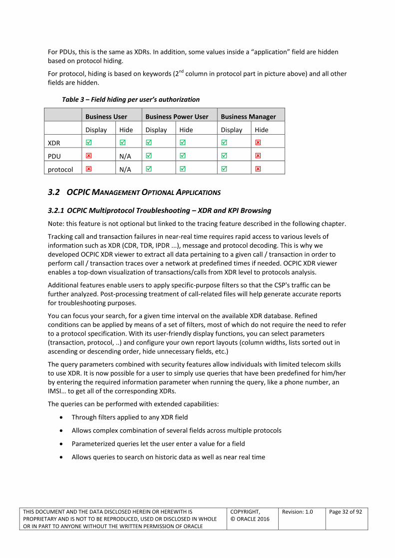
For PDUs, this is the same as XDRs. In addition, some values inside a “application” field are hidden based on protocol hiding.
For protocol, hiding is based on keywords (2nd column in protocol part in picture above) and all other fields are hidden.
Table 3 – Field hiding per user’s authorization
Business User Business Power User Business Manager
Display Hide Display Hide Display Hide
XDR
PDU N/A
protocol N/A
3.2 OCPIC MANAGEMENT OPTIONAL APPLICATIONS
3.2.1 OCPIC Multiprotocol Troubleshooting – XDR and KPI Browsing
Note: this feature is not optional but linked to the tracing feature described in the following chapter.
Tracking call and transaction failures in near-real time requires rapid access to various levels of information such as XDR (CDR, TDR, IPDR ...), message and protocol decoding. This is why we developed OCPIC XDR viewer to extract all data pertaining to a given call / transaction in order to perform call / transaction traces over a network at predefined times if needed. OCPIC XDR viewer enables a top-down visualization of transactions/calls from XDR level to protocols analysis.
Additional features enable users to apply specific-purpose filters so that the CSP's traffic can be further analyzed. Post-processing treatment of call-related files will help generate accurate reports for troubleshooting purposes.
You can focus your search, for a given time interval on the available XDR database. Refined conditions can be applied by means of a set of filters, most of which do not require the need to refer to a protocol specification. With its user-friendly display functions, you can select parameters (transaction, protocol, ..) and configure your own report layouts (column widths, lists sorted out in ascending or descending order, hide unnecessary fields, etc.)
The query parameters combined with security features allow individuals with limited telecom skills to use XDR. It is now possible for a user to simply use queries that have been predefined for him/her by entering the required information parameter when running the query, like a phone number, an IMSI… to get all of the corresponding XDRs.
The queries can be performed with extended capabilities:
Through filters applied to any XDR field
Allows complex combination of several fields across multiple protocols
Parameterized queries let the user enter a value for a field
Allows queries to search on historic data as well as near real time
THIS DOCUMENT AND THE DATA DISCLOSED HEREIN OR HEREWITH IS PROPRIETARY AND IS NOT TO BE REPRODUCED, USED OR DISCLOSED IN WHOLE OR IN PART TO ANYONE WITHOUT THE WRITTEN PERMISSION OF ORACLE
COPYRIGHT, © ORACLE 2016
Revision: 1.0 Page 33 of 92
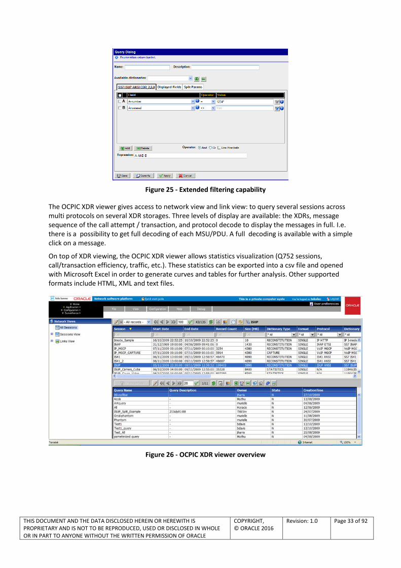
Figure 25 - Extended filtering capability
The OCPIC XDR viewer gives access to network view and link view: to query several sessions across multi protocols on several XDR storages. Three levels of display are available: the XDRs, message sequence of the call attempt / transaction, and protocol decode to display the messages in full. I.e. there is a possibility to get full decoding of each MSU/PDU. A full decoding is available with a simple click on a message.
On top of XDR viewing, the OCPIC XDR viewer allows statistics visualization (Q752 sessions, call/transaction efficiency, traffic, etc.). These statistics can be exported into a csv file and opened with Microsoft Excel in order to generate curves and tables for further analysis. Other supported formats include HTML, XML and text files.
Figure 26 - OCPIC XDR viewer overview

THIS DOCUMENT AND THE DATA DISCLOSED HEREIN OR HEREWITH IS PROPRIETARY AND IS NOT TO BE REPRODUCED, USED OR DISCLOSED IN WHOLE OR IN PART TO ANYONE WITHOUT THE WRITTEN PERMISSION OF ORACLE
COPYRIGHT, © ORACLE 2016
Revision: 1.0 Page 34 of 92
Figure 27 - Example OCPIC XDR viewer output
3.2.2 OCPIC Multiprotocol Troubleshooting – Call Tracing
For troubleshooting, the ability to perform call/transaction/session multi-protocol end-to-end tracing is mandatory for the following scenarios:
Network-related tracing, where for a global network, problem the user must be able to search on a specific failure cause, to extract a list of calls/transactions/sessions impacted by this problem, and then be able to trace on a chosen number.
Customer-related tracing, where by the customer, the user can enter for example the IMSI, without any previous query filter, and immediately get the details of calls/sessions related to this customer
Any protocols supervised by OCPIC, related to a call/transaction/session, can be traced as part of an end to end network wide call trace.
OCPIC Multiprotocol Troubleshooting is a scenario-less application. It is based on embedded intra-protocol rules and inter-protocol tracing that is part of an Oracle patent. What this means to the customer is that the users of the system do not need to have the protocol knowledge of how to map Protocol A to Protocol B when attempting to perform a network-wide call trace. The logic to perform this trace is built into the OCPIC Multiprotocol Troubleshooting application itself. OCPIC Multiprotocol Troubleshooting supports Intra-protocol traces functionality for all protocols supported by OCPIC. For example, a customer-related trace of a mobile can be done just by selecting a network view, entering an IMSI, and clicking on “trace now”. Another feature of Network diagram is to display time delay linked to each network elements through which signaling passes.
OCPIC Multiprotocol Troubleshooting handles & displays transactions/calls/sessions in an in-progress mode, including a Message Sequence Diagram. This requires partial CDR option for SIP and ISUP CDRs.
OCPIC Multiprotocol Troubleshooting has the capability to filter on display (ex: in GPRS, where several protocols can be on the same interface, the application can hide some protocols on display only.)

THIS DOCUMENT AND THE DATA DISCLOSED HEREIN OR HEREWITH IS PROPRIETARY AND IS NOT TO BE REPRODUCED, USED OR DISCLOSED IN WHOLE OR IN PART TO ANYONE WITHOUT THE WRITTEN PERMISSION OF ORACLE
COPYRIGHT, © ORACLE 2016
Revision: 1.0 Page 35 of 92
Other functions of OCPIC Multiprotocol Troubleshooting include:
Handling of some level 2 / level 3 messages in order to handle events like changeovers, alignment, SCTP path failures, as well as network management messages like TFA, TFP, etc.
Handling of SIGTRAN transport protocol layers messages.
Two modes (“real time” and “historical”) are supported by OCPIC Multiprotocol Troubleshooting
A trace can be performed either:
On a sub-network when a global network-related problem is analyzed, but with knowledge of the concerned area
On an entire network for some customer-related tracing. Example: for tracing in real-time a roamer (identified by an IMSI) who is supposed to enter the network, the point of entry being unknown
In addition to above-mentioned filters defined by administrator or user with specific rights, other users can define additional filters for their own needs.
To configure a trace, the user selects a network view which relates to the concerned data sessions, protocols, and/or related dictionaries.
Before starting a Network-related trace, the User starts a query filter based on any field from the concerned protocol dictionary. Then, in the list of XDRs matching the filter, the user selects an XDR to start a trace with a “start now” or a “begin time” (can be historical), and ends with an “end time” or “continue until cancelled”.
A real-time customer-related trace starts with a filter based on customer identifier like MSISDN or IMSI, or terminal identification like IMEI. The trace starts with a “start now” or a “begin time”, and ends with an “end time” or “continue until cancelled”.
Any protocol supervised by OCPIC can be traced at the same time. So it will be easy to find every operation concerning a subscriber's activities on wire line and wireless networks. Exchange of signaling units and user packets between different elements using different protocols can be highlighted for further investigation purposes. As probes can be located in different areas of the network, end-to-end call tracing will be performed in order to provide a centralized view of the network.
-
Figure 28 - OCPIC Multiprotocol Troubleshooting screen capture

THIS DOCUMENT AND THE DATA DISCLOSED HEREIN OR HEREWITH IS PROPRIETARY AND IS NOT TO BE REPRODUCED, USED OR DISCLOSED IN WHOLE OR IN PART TO ANYONE WITHOUT THE WRITTEN PERMISSION OF ORACLE
COPYRIGHT, © ORACLE 2016
Revision: 1.0 Page 36 of 92
Figure 29 - Example of OCPIC Multiprotocol Troubleshooting output
Figure 30 - Ladder diagram
Trace export: It is possible to export a trace in the following formats:
- Native ZIP - CSV - TXT - HTML - XML - PCAP (SIGTRAN and Diameter)
THIS DOCUMENT AND THE DATA DISCLOSED HEREIN OR HEREWITH IS PROPRIETARY AND IS NOT TO BE REPRODUCED, USED OR DISCLOSED IN WHOLE OR IN PART TO ANYONE WITHOUT THE WRITTEN PERMISSION OF ORACLE
COPYRIGHT, © ORACLE 2016
Revision: 1.0 Page 37 of 92
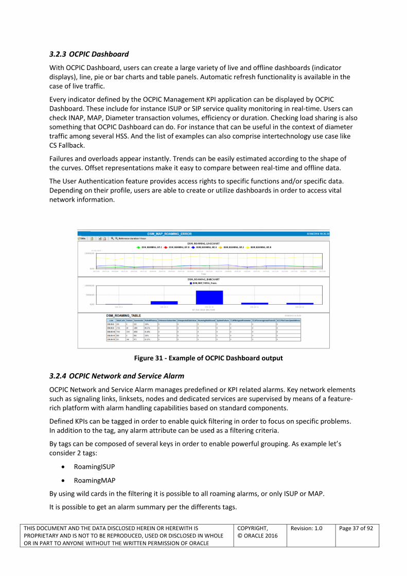
3.2.3 OCPIC Dashboard
With OCPIC Dashboard, users can create a large variety of live and offline dashboards (indicator displays), line, pie or bar charts and table panels. Automatic refresh functionality is available in the case of live traffic.
Every indicator defined by the OCPIC Management KPI application can be displayed by OCPIC Dashboard. These include for instance ISUP or SIP service quality monitoring in real-time. Users can check INAP, MAP, Diameter transaction volumes, efficiency or duration. Checking load sharing is also something that OCPIC Dashboard can do. For instance that can be useful in the context of diameter traffic among several HSS. And the list of examples can also comprise intertechnology use case like CS Fallback.
Failures and overloads appear instantly. Trends can be easily estimated according to the shape of the curves. Offset representations make it easy to compare between real-time and offline data.
The User Authentication feature provides access rights to specific functions and/or specific data. Depending on their profile, users are able to create or utilize dashboards in order to access vital network information.
Figure 31 - Example of OCPIC Dashboard output
3.2.4 OCPIC Network and Service Alarm
OCPIC Network and Service Alarm manages predefined or KPI related alarms. Key network elements such as signaling links, linksets, nodes and dedicated services are supervised by means of a feature-rich platform with alarm handling capabilities based on standard components.
Defined KPIs can be tagged in order to enable quick filtering in order to focus on specific problems. In addition to the tag, any alarm attribute can be used as a filtering criteria.
By tags can be composed of several keys in order to enable powerful grouping. As example let’s consider 2 tags:
RoamingISUP
RoamingMAP
By using wild cards in the filtering it is possible to all roaming alarms, or only ISUP or MAP.
It is possible to get an alarm summary per the differents tags.

THIS DOCUMENT AND THE DATA DISCLOSED HEREIN OR HEREWITH IS PROPRIETARY AND IS NOT TO BE REPRODUCED, USED OR DISCLOSED IN WHOLE OR IN PART TO ANYONE WITHOUT THE WRITTEN PERMISSION OF ORACLE
COPYRIGHT, © ORACLE 2016
Revision: 1.0 Page 38 of 92
It is possible for people in charge of managing alarms to acknowledge or manually terminate an alarm. Their login as well as date and time will be stored for future reference.
The User Authentication feature provides access rights to specific functions and/or specific data. Depending on their profile, users will be able to create or utilize filters in order to access vital network information.
In the viewer section, they will only see objects they have authorization for, and thus only see their corresponding alarms and not the complete set. This allows a better focus on managing the part of the network or service or SLA they are responsible for.
Figure 32 - Example of OCPIC Network and Service Alarm output
3.2.5 Inter-Application Link on KPI alarms
OCPIC includes inter-applications links in order to improve root causes analysis process. Several drill down capabilities are available.
From any alarm on a OCPIC Network and Service Alarm, the user can drill down details of the evolution of KPI generating this alarm. The graphical display helps to distinguish e.g. problems due to a sport event from those that are due a longer trend. Drill to KPI details provides additional measures complementing the information provide by the indicator triggering the alarm.
Figure 33 - Drill-down from OCPIC Network and Service Alarm KPI Alarm to OCPIC Dashboard or to OCPIC XDR browser
THIS DOCUMENT AND THE DATA DISCLOSED HEREIN OR HEREWITH IS PROPRIETARY AND IS NOT TO BE REPRODUCED, USED OR DISCLOSED IN WHOLE OR IN PART TO ANYONE WITHOUT THE WRITTEN PERMISSION OF ORACLE
COPYRIGHT, © ORACLE 2016
Revision: 1.0 Page 39 of 92
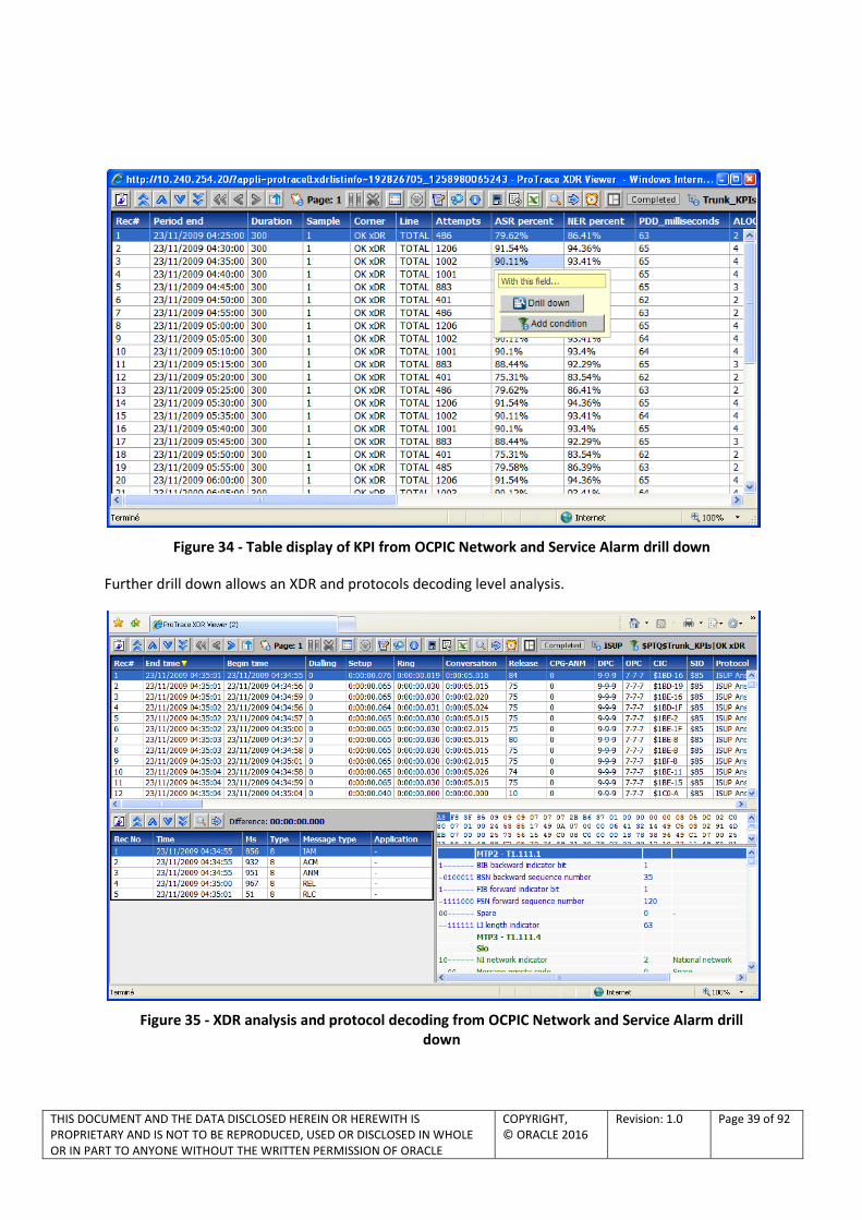
Figure 34 - Table display of KPI from OCPIC Network and Service Alarm drill down
Further drill down allows an XDR and protocols decoding level analysis.
Figure 35 - XDR analysis and protocol decoding from OCPIC Network and Service Alarm drill down

THIS DOCUMENT AND THE DATA DISCLOSED HEREIN OR HEREWITH IS PROPRIETARY AND IS NOT TO BE REPRODUCED, USED OR DISCLOSED IN WHOLE OR IN PART TO ANYONE WITHOUT THE WRITTEN PERMISSION OF ORACLE
COPYRIGHT, © ORACLE 2016
Revision: 1.0 Page 40 of 92
3.2.6 Alarm forwarding
To provide CSPs with real time monitoring of the networks, it is important that all alarms are sent to one single application. The alarm forwarding allows a seamless integration into OSS / fault management platform.
Alarm forwarding allows the generation of e-mails too. Up to 10 rules can be defined to forward emails. With each rule an email distribution list can be defined. For instance alarms on servers can be sent to a department and alarms on SLA can be sent to a different department
Figure 36 - Example of alarm forwarding filters
Also for some critical alarms it could be convenient to receive them by email at your desk or on your mobile handset.
In accordance with ITU X.733 recommendations, OCPIC Network and Service Alarm can forward traffic, service and system alarms to an upper global fault management platform or to a mailbox. With OCPIC Network and Service Alarm events forwarding discriminator, you can define rules to allow the actual forwarding, filter alarms based on user-defined rules, and to forward filtered alarms. This is an ideal combination of functions to manage protocol errors, errors in message signal units, hardware failure notifications and to make network administrators aware of real-time QoS indicators.
An SNMP agent in accordance with ITU X.721 recommendation is available and its MIB can be shared in order to integrate OCPIC alarms into an umbrella system.
Figure 37 - Example of alarm forwarding configuration for destination

THIS DOCUMENT AND THE DATA DISCLOSED HEREIN OR HEREWITH IS PROPRIETARY AND IS NOT TO BE REPRODUCED, USED OR DISCLOSED IN WHOLE OR IN PART TO ANYONE WITHOUT THE WRITTEN PERMISSION OF ORACLE
COPYRIGHT, © ORACLE 2016
Revision: 1.0 Page 41 of 92
Figure 38 - Example of alarm forwarding configuration for filtering
3.2.7 OCPIC SS7 Management – SS7 network diagnostic (Integrated Acquisition)
OCPIC SS7 Management is an application developed to analyze SS7 link information from the OCPIC Integrated Acquisition for low speed links (LSLs) and high speed links (HSL).
OCPIC SS7 Management provides immediate visual notification, and details, of any L2/L3 events that could impede or prevent the transport of SS7 traffic in a CSP’s network. The CSP is provided with immediate indication of revenue threatening situations and can move quickly to initiate corrective actions. Further, the effectiveness of any corrective actions will be immediately displayed thereby providing an additional level of confidence that the problem has really been fixed.
Functioning as a near real-time application, OCPIC SS7 Management indicates status of nodes, linksets and links that make up a network. It provides continuous assessment of overall network health by displaying the link(s)/node(s) status and link state counters within a network. Following is the architecture overview:
THIS DOCUMENT AND THE DATA DISCLOSED HEREIN OR HEREWITH IS PROPRIETARY AND IS NOT TO BE REPRODUCED, USED OR DISCLOSED IN WHOLE OR IN PART TO ANYONE WITHOUT THE WRITTEN PERMISSION OF ORACLE
COPYRIGHT, © ORACLE 2016
Revision: 1.0 Page 42 of 92
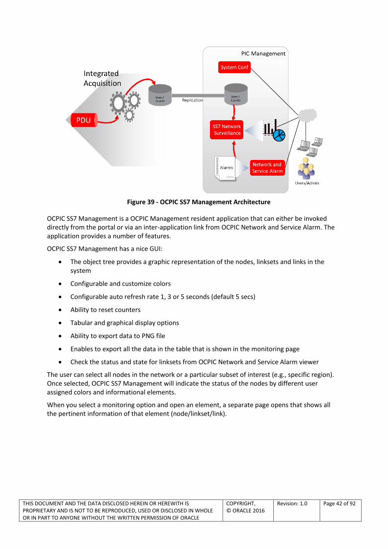
Figure 39 - OCPIC SS7 Management Architecture
OCPIC SS7 Management is a OCPIC Management resident application that can either be invoked directly from the portal or via an inter-application link from OCPIC Network and Service Alarm. The application provides a number of features.
OCPIC SS7 Management has a nice GUI:
The object tree provides a graphic representation of the nodes, linksets and links in the system
Configurable and customize colors
Configurable auto refresh rate 1, 3 or 5 seconds (default 5 secs)
Ability to reset counters
Tabular and graphical display options
Ability to export data to PNG file
Enables to export all the data in the table that is shown in the monitoring page
Check the status and state for linksets from OCPIC Network and Service Alarm viewer
The user can select all nodes in the network or a particular subset of interest (e.g., specific region). Once selected, OCPIC SS7 Management will indicate the status of the nodes by different user assigned colors and informational elements.
When you select a monitoring option and open an element, a separate page opens that shows all the pertinent information of that element (node/linkset/link).

THIS DOCUMENT AND THE DATA DISCLOSED HEREIN OR HEREWITH IS PROPRIETARY AND IS NOT TO BE REPRODUCED, USED OR DISCLOSED IN WHOLE OR IN PART TO ANYONE WITHOUT THE WRITTEN PERMISSION OF ORACLE
COPYRIGHT, © ORACLE 2016
Revision: 1.0 Page 43 of 92
From the Node View the user can click on any node or subset of nodes and OCPIC SS7 Management will expand the view to indicate the status of the linksets associated with the node(s). From this view the user can further expand the view to the individual links themselves. This is illustrated below.
Figure 40 - Linkset view
The OCPIC SS7 Management application presents a user with a choice of following monitoring counts and statistics for the element (node/linkset/link):
Link status - monitors the status of a link(s): state of the link and message counter per SIO
Link state - monitors the state of a link(s): counters about state messages, retransmission and errors
NetMgmt transfer signals - monitors the transfer information
NetMgmt signal route - monitors the route information
NetMgmt others - monitors other information about inhibition and restart
3.2.8 OCPIC SS7 Management – SIGTRAN network diagnostic (Integrated Acquisition)
OCPIC SS7 Management manage also SIGTRAN based SS7 networks gathered from the OCPIC Integrated Acquisition.
OCPIC SS7 Management provides immediate visual notification, and details, of SIGTRAN events that could impede or prevent the transport of SIGTRAN traffic in an CSP’s network.
OCPIC SS7 Management monitors and displays diagnostics data (status and counters) for SIGTRAN layers e.g. SCTP, M2PA, M3UA and SUA.
Functioning as a near real-time application, OCPIC SS7 Management indicates state and status of application servers, application server processes, links, linksets, associations, cards that make up a network. OCPIC SS7 Management application is integrated into OCPIC Management and functions on a network view context. OCPIC SS7 Management provides the capability to view overall status of elements as well as to drill down to individual links and associations

THIS DOCUMENT AND THE DATA DISCLOSED HEREIN OR HEREWITH IS PROPRIETARY AND IS NOT TO BE REPRODUCED, USED OR DISCLOSED IN WHOLE OR IN PART TO ANYONE WITHOUT THE WRITTEN PERMISSION OF ORACLE
COPYRIGHT, © ORACLE 2016
Revision: 1.0 Page 44 of 92
There is a nice GUI:
Display status and statistics on the various SIGTRAN application server, application server processes, linksets, links, cards and associations that make up the network.
Choice of following monitoring counts and statistics:
Top N occupancy and TPS details
Configurable and customizable colors
Configurable auto refresh rate 1, 3 or 5 seconds (default 5 secs)
Ability to reset counters
Tabular and graphical display options
Allows the user to select which counters and elements to display and choose the display type: tabular or graphical
Ability to customize display
Hide columns
Change layout
Ability to export data to PNG file
Enables to export all the data in the table that is shown in the monitoring page
Figure 41 – SS7 Management SIGTRAN main screen
3.2.8.1 STATE COUNTERS
SCTP:
Heartbeat requests Rx/Tx
Heartbeat ACKS Rx/Tx
Operation Errors Rx/Tx
Shutdown Rx/Tx
Abort Rx/Tx
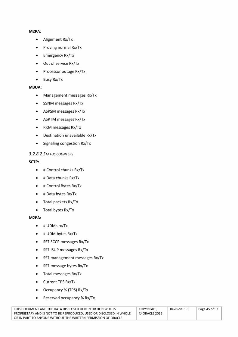
THIS DOCUMENT AND THE DATA DISCLOSED HEREIN OR HEREWITH IS PROPRIETARY AND IS NOT TO BE REPRODUCED, USED OR DISCLOSED IN WHOLE OR IN PART TO ANYONE WITHOUT THE WRITTEN PERMISSION OF ORACLE
COPYRIGHT, © ORACLE 2016
Revision: 1.0 Page 45 of 92
M2PA:
Alignment Rx/Tx
Proving normal Rx/Tx
Emergency Rx/Tx
Out of service Rx/Tx
Processor outage Rx/Tx
Busy Rx/Tx
M3UA:
Management messages Rx/Tx
SSNM messages Rx/Tx
ASPSM messages Rx/Tx
ASPTM messages Rx/Tx
RKM messages Rx/Tx
Destination unavailable Rx/Tx
Signaling congestion Rx/Tx
3.2.8.2 STATUS COUNTERS
SCTP:
# Control chunks Rx/Tx
# Data chunks Rx/Tx
# Control Bytes Rx/Tx
# Data bytes Rx/Tx
Total packets Rx/Tx
Total bytes Rx/Tx
M2PA:
# UDMs rx/Tx
# UDM bytes Rx/Tx
SS7 SCCP messages Rx/Tx
SS7 ISUP messages Rx/Tx
SS7 management messages Rx/Tx
SS7 message bytes Rx/Tx
Total messages Rx/Tx
Current TPS Rx/Tx
Occupancy % (TPS) Rx/Tx
Reserved occupancy % Rx/Tx

THIS DOCUMENT AND THE DATA DISCLOSED HEREIN OR HEREWITH IS PROPRIETARY AND IS NOT TO BE REPRODUCED, USED OR DISCLOSED IN WHOLE OR IN PART TO ANYONE WITHOUT THE WRITTEN PERMISSION OF ORACLE
COPYRIGHT, © ORACLE 2016
Revision: 1.0 Page 46 of 92
M3UA:
Non-data messages Rx/Tx
Non-data message bytes Rx/Tx
Data messages Rx/Tx
Data message bytes Rx/Tx
Current TPS Rx/Tx
SCCP message Rx/Tx
ISUP message Rx/Tx
Total messages Rx/Tx
% Total Occupancy (TPS) Rx/Tx
Reserved occupancy % (TPS) Rx/Tx (Available only for links)
SUA :
Management messages Rx/Tx
Management message bytes Rx/Tx
Data messages (CLDT + CLDR) Rx/Tx
Data messages (CLDT + CLDR) bytes Rx/Tx
Total messages Rx/Tx
Total messages bytes Rx/Tx
Current TPS Rx/Tx
Total occupancy % Rx/Tx
3.2.9 Q.752 Application (EAGLE Integrated Acquisition)
In order to manage effectively the resources provided by a signaling system n° 7 network, it is necessary to monitor and measure the present, and estimate the future performance, utilization and availability of these resources.
The values measured are compared to a predetermined threshold for "regular traffic." When a value exceeds the predetermined threshold, an alarm normally is generated, and a notification might be sent to maintenance personnel. In this way, SS7 network monitoring helps the CSP detect security breaches.
Q.752 defines a standard set of measurements (statistical counts) and alarms for monitoring the health of SS7 networks.
Q.752 application supports a large number of counts and statistics. A snapshot of the Q752 counters that are supported by the OCPIC system is as follows:

THIS DOCUMENT AND THE DATA DISCLOSED HEREIN OR HEREWITH IS PROPRIETARY AND IS NOT TO BE REPRODUCED, USED OR DISCLOSED IN WHOLE OR IN PART TO ANYONE WITHOUT THE WRITTEN PERMISSION OF ORACLE
COPYRIGHT, © ORACLE 2016
Revision: 1.0 Page 47 of 92
Figure 42 - Q.752 counters supported
The Q.752 counters need to be activated at the OCPIC Integrated Acquisition and thresholds for the generation of alarms must be set. By default the configuration sets the status of the counters to true and has default threshold values set. The user can modify the low and high threshold of any of the counts and the effect will take place after 10 seconds.
Figure 43 - Q.752 alarm threshold
The XDR browser application is used to view these Q.752 counters. All the counts are stored in the sessions. Q752 sessions can be identified by the session name. The session name will typically have Mediation Subsystem name_<Q752 Counter name> For example: Table 1 session for OCPIC

THIS DOCUMENT AND THE DATA DISCLOSED HEREIN OR HEREWITH IS PROPRIETARY AND IS NOT TO BE REPRODUCED, USED OR DISCLOSED IN WHOLE OR IN PART TO ANYONE WITHOUT THE WRITTEN PERMISSION OF ORACLE
COPYRIGHT, © ORACLE 2016
Revision: 1.0 Page 48 of 92
Mediation (IXP) Subsystem that has name: Mediation’ Subsystem1 will look as “Mediation’ Subsystem1_Q752_1 “.
3.2.10 SIGTRAN statistics and alarms
OCPIC provides SIGTRAN statistics on the following layers:
SCTP
M2PA
M3UA
SUA
3.2.10.1 SCTP STATISTIC AND ALARMS
Statistics provided:
SCTP association availability
SCTP association performance (e.g. message counts, message rate, checksum error counts, etc)
SCTP retransmissions
Alarms:
Alarms related to the above statistics can be generated thanks to OCPIC Management KPI application: Statistical alarm if % SCTP retransmissions is higher than a user-defined threshold. OCPIC Management KPI application alarms generated on Statistics session
SCTP associations loss and recovery alarms (endpoint failure detection)
SCTP path failure loss and recovery alarms (multi-homed path loss)
3.2.10.2 M2PA STATISTICS AND ALARMS
Statistics :
Number of Signaling link Congestion
% of time a link is congested in a statistics period
Number of Changeovers
Number of Link Alignment procedures
Alarms
Alarms related to the above statistics can be generated thanks to OCPIC Management KPI application.
Alarm on detection of transmit congestion
Alarm on changeovers: alarm if number of changeovers is higher as a user-defined threshold on the statistics period
Alarm on link alignment procedures: alarm if number of alignment is higher as a user-defined threshold on the statistics period

THIS DOCUMENT AND THE DATA DISCLOSED HEREIN OR HEREWITH IS PROPRIETARY AND IS NOT TO BE REPRODUCED, USED OR DISCLOSED IN WHOLE OR IN PART TO ANYONE WITHOUT THE WRITTEN PERMISSION OF ORACLE
COPYRIGHT, © ORACLE 2016
Revision: 1.0 Page 49 of 92
3.2.10.3 M3UA STATISTICS AND ALARMS
Statistics are provided per link ID (Association), per point code and per user part:
Number of events & total duration: (per association & point code)
Signaling congestion (SCON)
Destination unavailable (DUNA)
Destination user part unavailable (DUPU): also per user part
Number of ASP (Application service part) down and total duration per statistical period
Number of changeovers: per link ID and point code
Alarms:
Alarms related to the above statistics can be generated thanks to OCPIC Management KPI application.
Statistical alarms on the number of occurrences of the events: SCON, DUNA, DUPU
Statistical alarm on the number of changeovers: per link ID & point code
Statistical alarm on total ASP down per period
3.2.10.4 SUA STATISTICS
Statistics per association and point codes:
Number of events & total duration
Signaling congestion (SCON)
Destination unavailable (DUNA)
Destination restricted (DRST)
Destination user part unavailable (DUPU): also per user part
Number of ASP (Application service part) down and total duration
Number of connection oriented SUA messages sent & received per period (Connection refused: COREF)
Related alarms can be generated thanks to OCPIC Management KPI application:
Statistical alarms on the number of occurrences of the events: SCON, DUNA, DRST, DUPU
Statistical alarm on total ASP down per period
Statistical alarms on connection oriented SUA messages sent & received per period (Connection Refused: COREF)
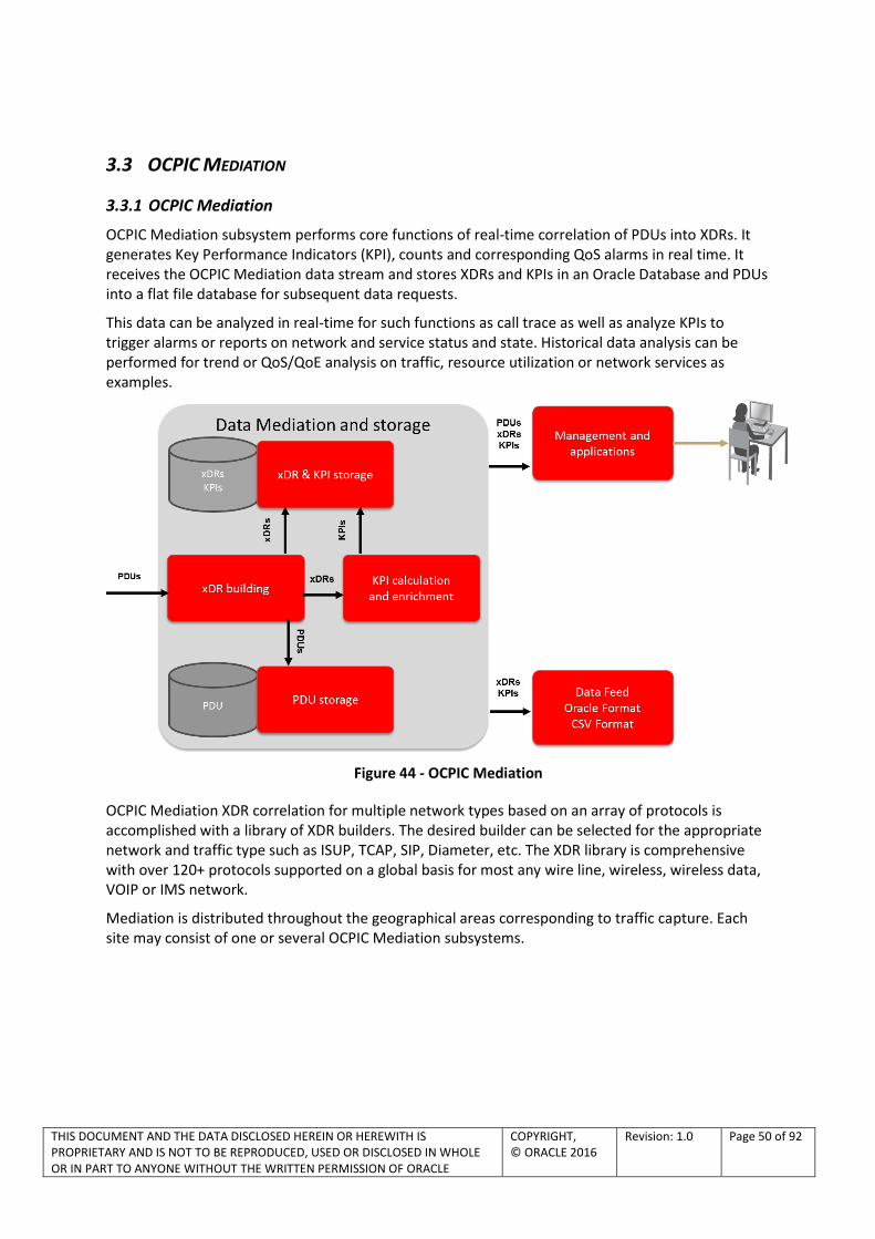
THIS DOCUMENT AND THE DATA DISCLOSED HEREIN OR HEREWITH IS PROPRIETARY AND IS NOT TO BE REPRODUCED, USED OR DISCLOSED IN WHOLE OR IN PART TO ANYONE WITHOUT THE WRITTEN PERMISSION OF ORACLE
COPYRIGHT, © ORACLE 2016
Revision: 1.0 Page 50 of 92
3.3 OCPIC MEDIATION
3.3.1 OCPIC Mediation
OCPIC Mediation subsystem performs core functions of real-time correlation of PDUs into XDRs. It generates Key Performance Indicators (KPI), counts and corresponding QoS alarms in real time. It receives the OCPIC Mediation data stream and stores XDRs and KPIs in an Oracle Database and PDUs into a flat file database for subsequent data requests.
This data can be analyzed in real-time for such functions as call trace as well as analyze KPIs to trigger alarms or reports on network and service status and state. Historical data analysis can be performed for trend or QoS/QoE analysis on traffic, resource utilization or network services as examples.
Figure 44 - OCPIC Mediation
OCPIC Mediation XDR correlation for multiple network types based on an array of protocols is accomplished with a library of XDR builders. The desired builder can be selected for the appropriate network and traffic type such as ISUP, TCAP, SIP, Diameter, etc. The XDR library is comprehensive with over 120+ protocols supported on a global basis for most any wire line, wireless, wireless data, VOIP or IMS network.
Mediation is distributed throughout the geographical areas corresponding to traffic capture. Each site may consist of one or several OCPIC Mediation subsystems.

THIS DOCUMENT AND THE DATA DISCLOSED HEREIN OR HEREWITH IS PROPRIETARY AND IS NOT TO BE REPRODUCED, USED OR DISCLOSED IN WHOLE OR IN PART TO ANYONE WITHOUT THE WRITTEN PERMISSION OF ORACLE
COPYRIGHT, © ORACLE 2016
Revision: 1.0 Page 51 of 92
A OCPIC Mediation subsystem is a collection of servers organized in 3 functional areas as depicted in the following diagram:
Figure 45 - OCPIC Mediation subsystem overview
3.3.1.1 OCPIC MEDIATION SERVERS
Mediation servers receive real time PDU flows from OCPIC Integrated or stand-alone Acquisition, correlate them and build XDRs accordingly. Process includes dynamic enrichment consisting of enriching XDR with fields that are not present in the related PDUs (e.g. IMSI) but come from the global context (e.g. mobile context) kept by the XDR builder.
Static enrichment may optionally add fields to XDR according to an external user table (e.g. add a network element label from its IP address).
Generated XDRs feed data into OCPIC Management KPI application for generating KPIs and related alarms in real time.
Mediation servers work in load sharing mode so that the system can be easily sized according to the total throughput to be processed.
Virtualized Mediation server:
OCPIC Mediation server can also be virtualized, using VMware or KVM hypervisor (see section 3.6).
3.3.1.2 OCPIC XDR STORAGE POOL
XDR storage pool is the OCPIC XDR and KPI real time data base. A pool is a virtual server consisting of an extensible number of servers allocated to storage and independently from their physical location in enclosures. Each server of the pool runs an autonomous Oracle Database and has its own disk space. Storage is dynamically load-balanced throughout servers of the pool so that a given XDR or KPI session (e.g. MAP XDR session) is evenly distributed over the servers.
If a server goes down, then the xDR traffic is automatically taken over by the other servers of the pool without any loss of data (optional, option N+1 redundancy).

THIS DOCUMENT AND THE DATA DISCLOSED HEREIN OR HEREWITH IS PROPRIETARY AND IS NOT TO BE REPRODUCED, USED OR DISCLOSED IN WHOLE OR IN PART TO ANYONE WITHOUT THE WRITTEN PERMISSION OF ORACLE
COPYRIGHT, © ORACLE 2016
Revision: 1.0 Page 52 of 92
A query to the data base from an application is executed in parallel over all the servers of the pool (distributed queries) so that response time is reduced and the system can scale up to increase the number of simultaneous users.
3.3.1.3 OCPIC PDU STORAGE POOL
PDU storage server stores the PDUs originated from Mediation servers into its integrated PDU database. PDU servers, as XDR servers, are grouped into a pool. Each server of the pool runs an autonomous flat PDU database and has its own disk space. PDU storage is dynamically load-balanced throughout servers of the pool so that PDUs are evenly distributed over the servers.
If a server goes down, then the PDU traffic is automatically taken over by the other servers of the pool without any loss of data (optional, option N+1 redundancy).
Architecture advantages summary:
Provide flexible linear scaling up:
o add a storage server (hot plug insertion) to increase storage capacity or number of users independently from Mediation servers
o or add PDU servers independently from Mediation and XDR storage servers
Provide optional redundancy mechanism with automatic server failover. This will assure no loss of insertion data in case of server failure

THIS DOCUMENT AND THE DATA DISCLOSED HEREIN OR HEREWITH IS PROPRIETARY AND IS NOT TO BE REPRODUCED, USED OR DISCLOSED IN WHOLE OR IN PART TO ANYONE WITHOUT THE WRITTEN PERMISSION OF ORACLE
COPYRIGHT, © ORACLE 2016
Revision: 1.0 Page 53 of 92
3.3.2 Data Records, Packet Data Units and KPIs Storage on Customer IT infrastructure
As a full alternative to OCPIC internal storage described in sections 3.3.1.2 and 3.3.1.3, it is possible for the customer to use his existing IT storage infrastructure instead of OCPIC internal storage servers. This can be done on a mediation site by site basis
Main advantages for the customer are as follows:
- saving CAPEX and OPEX costs by using Customer existing infrastructure (cloud)
- enabling Customer to size storage duration as needed independently of the limitation of the OCPIC internal storage
- enabling Customer to open access to the databases to non OCPIC Users and Applications
Customers Oracle Database
OCPIC Mediation OCPIC data record storage
Customers NFS server
OCPIC PDU storageManagement &
Applications
OCPIC domain Customer domain
Figure 46 – Data Records, Packet Data Units and KPIs Storage on Customer IT sorage infrastructure
3.3.3 XDR builders and protocols
3.3.3.1 XDR BUILDERS
OCPIC generates protocol specific XDRs in real-time in the OCPIC Mediation layer. XDR builders are correlating protocol exchanges in real time. XDR represent the high value from network information. Automatic enrichment of XDR is performed by correlation of multiple protocols allowing integration of IMSI, MSISDN, cell ID, EMEI, APN etc in XDR.
The XDR can be from multiple types:
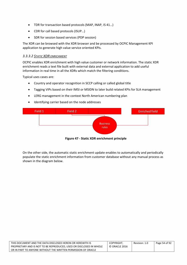
THIS DOCUMENT AND THE DATA DISCLOSED HEREIN OR HEREWITH IS PROPRIETARY AND IS NOT TO BE REPRODUCED, USED OR DISCLOSED IN WHOLE OR IN PART TO ANYONE WITHOUT THE WRITTEN PERMISSION OF ORACLE
COPYRIGHT, © ORACLE 2016
Revision: 1.0 Page 54 of 92
TDR for transaction based protocols (MAP, INAP, IS 41…)
CDR for call based protocols (ISUP…)
SDR for session based services (PDP session)
The XDR can be browsed with the XDR browser and be processed by OCPIC Management KPI application to generate high value service oriented KPIs.
3.3.3.2 STATIC XDR ENRICHMENT
OCPIC enables XDR enrichment with high value customer or network information. The static XDR enrichment reads a text file built with external data and external application to add useful information in real time in all the XDRs which match the filtering conditions.
Typical uses cases are:
Country and operator recognition in SCCP calling or called global title
Tagging VIPs based on their IMSI or MSIDN to later build related KPIs for SLA management
LERG management in the context North American numbering plan
Identifying carrier based on the node addresses
Figure 47 - Static XDR enrichment principle
On the other side, the automatic static enrichment update enables to automatically and periodically populate the static enrichment information from customer database without any manual process as shown in the diagram below.
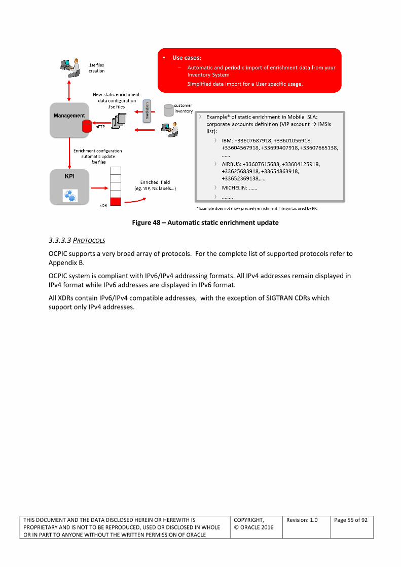
THIS DOCUMENT AND THE DATA DISCLOSED HEREIN OR HEREWITH IS PROPRIETARY AND IS NOT TO BE REPRODUCED, USED OR DISCLOSED IN WHOLE OR IN PART TO ANYONE WITHOUT THE WRITTEN PERMISSION OF ORACLE
COPYRIGHT, © ORACLE 2016
Revision: 1.0 Page 55 of 92
Figure 48 – Automatic static enrichment update
3.3.3.3 PROTOCOLS
OCPIC supports a very broad array of protocols. For the complete list of supported protocols refer to Appendix B.
OCPIC system is compliant with IPv6/IPv4 addressing formats. All IPv4 addresses remain displayed in IPv4 format while IPv6 addresses are displayed in IPv6 format.
All XDRs contain IPv6/IPv4 compatible addresses, with the exception of SIGTRAN CDRs which support only IPv4 addresses.
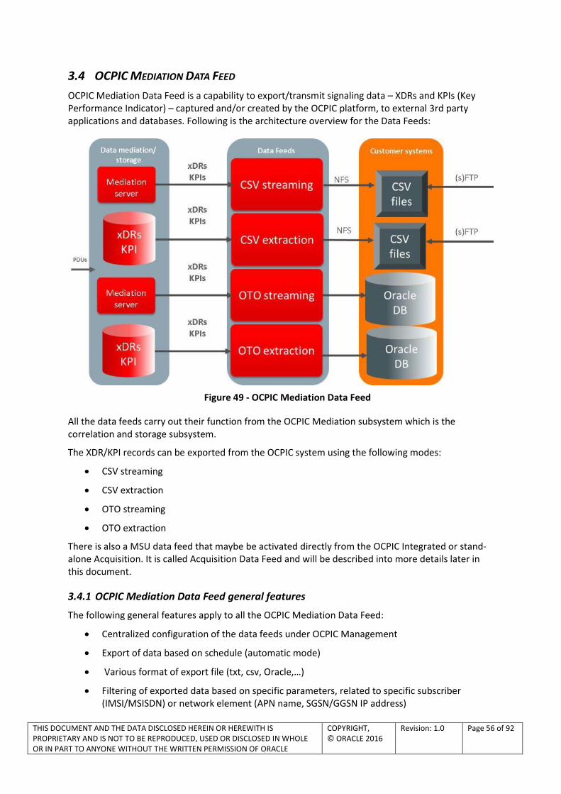
THIS DOCUMENT AND THE DATA DISCLOSED HEREIN OR HEREWITH IS PROPRIETARY AND IS NOT TO BE REPRODUCED, USED OR DISCLOSED IN WHOLE OR IN PART TO ANYONE WITHOUT THE WRITTEN PERMISSION OF ORACLE
COPYRIGHT, © ORACLE 2016
Revision: 1.0 Page 56 of 92
3.4 OCPIC MEDIATION DATA FEED
OCPIC Mediation Data Feed is a capability to export/transmit signaling data – XDRs and KPIs (Key Performance Indicator) – captured and/or created by the OCPIC platform, to external 3rd party applications and databases. Following is the architecture overview for the Data Feeds:
Figure 49 - OCPIC Mediation Data Feed
All the data feeds carry out their function from the OCPIC Mediation subsystem which is the correlation and storage subsystem.
The XDR/KPI records can be exported from the OCPIC system using the following modes:
CSV streaming
CSV extraction
OTO streaming
OTO extraction
There is also a MSU data feed that maybe be activated directly from the OCPIC Integrated or stand-alone Acquisition. It is called Acquisition Data Feed and will be described into more details later in this document.
3.4.1 OCPIC Mediation Data Feed general features
The following general features apply to all the OCPIC Mediation Data Feed:
Centralized configuration of the data feeds under OCPIC Management
Export of data based on schedule (automatic mode)
Various format of export file (txt, csv, Oracle,…)
Filtering of exported data based on specific parameters, related to specific subscriber (IMSI/MSISDN) or network element (APN name, SGSN/GGSN IP address)

THIS DOCUMENT AND THE DATA DISCLOSED HEREIN OR HEREWITH IS PROPRIETARY AND IS NOT TO BE REPRODUCED, USED OR DISCLOSED IN WHOLE OR IN PART TO ANYONE WITHOUT THE WRITTEN PERMISSION OF ORACLE
COPYRIGHT, © ORACLE 2016
Revision: 1.0 Page 57 of 92
Data can be exported from multiple OCPIC Mediation sub-systems
Monitor the status and progress of the OCPIC Mediation Data Feed
System surveillance and recovery
3.4.2 OCPIC Acquisition Data Feed - MSU data feed from the OCPIC Integrated or Probed Acquisition
Figure 50 – OCPIC Acquisition Data Feed Architecture
Oracle has developed OCPIC Acquisition Data Feed to allow direct MSU data feed from the OCPIC Integrated or Probed Acquisition to the customer 3rd party server. OCPIC Acquisition Data Feed is a Oracle provided software compatible with Linux OS. It establishes a Linux process that allows for the establishment of a LAN/WAN connection from all XMFs at a site to the customer 3rd party server. The customer server can be located at the site with the OCPIC Acquisition or may be located remotely. If connection is lost an alarm is triggered.
The MSU/IP packets are stored in single file/single directory, or multiple files/single directory or multiple files/multiple directories according to the configuration. Each record contains the full MSU/IP packet + a header. The file is rotated at configurable interval (from 15 sec to 1 hour) and it is renamed when it is closed.
OCPIC Acquisition Data Feed is compatible with the filterable MSU capability of OCPIC. It is available from all of the following OCPIC Integrated or stand-alone Acquisition interfaces, for any of the protocol carried on the interface:
LSL/HSL (through converter)
SIGTRAN
IP
EAGLE

THIS DOCUMENT AND THE DATA DISCLOSED HEREIN OR HEREWITH IS PROPRIETARY AND IS NOT TO BE REPRODUCED, USED OR DISCLOSED IN WHOLE OR IN PART TO ANYONE WITHOUT THE WRITTEN PERMISSION OF ORACLE
COPYRIGHT, © ORACLE 2016
Revision: 1.0 Page 58 of 92
3.5 OCPIC DATA ACQUISITION
Data Acquisition
EAGLE Integrated Acquisition
Data Acquisition
ProbedAcqusition
converter
Data Mediation & Storage
Mediation
PDUs
PDUs
PDUsSS7-
TDM/SIGTRAN
Diameter
2G/3G/4G
IMS
Gb
SS7 - TDM
converter
OCDSR Integrated Acquisition
PDUs
Figure 51 – OCPIC Acquisition Architecture
3.5.1 OCPIC Integrated Acquisition
3.5.1.1 OCPIC INTEGRATED ACQUISITION ARCHITECTURE
OCPIC Integrated Acquisition is a data acquisition component that provides integrated signaling acquisition in conjunction with the EAGLE.
Inputs to the OCPIC Integrated Acquisition are signaling frames acquired from EAGLE. Outputs from the OCPIC Integrated Acquisition are filtered frames with timestamps. The primary functions of the OCPIC Integrated Acquisition are:
Data Acquisition: to support a highly, reliable architecture for signaling message capture.
6 h buffering, this option allows frames to be buffered to avoid data loss in the event of network problems.
Filtering to ensure non-relevant frames are identified and discarded. The filters, which consist of any combination of fields, are fully configurable. Arithmetic expressions can also be included.
Routing to provide secure transport to the proper mediation processing resource according to configurable criteria.
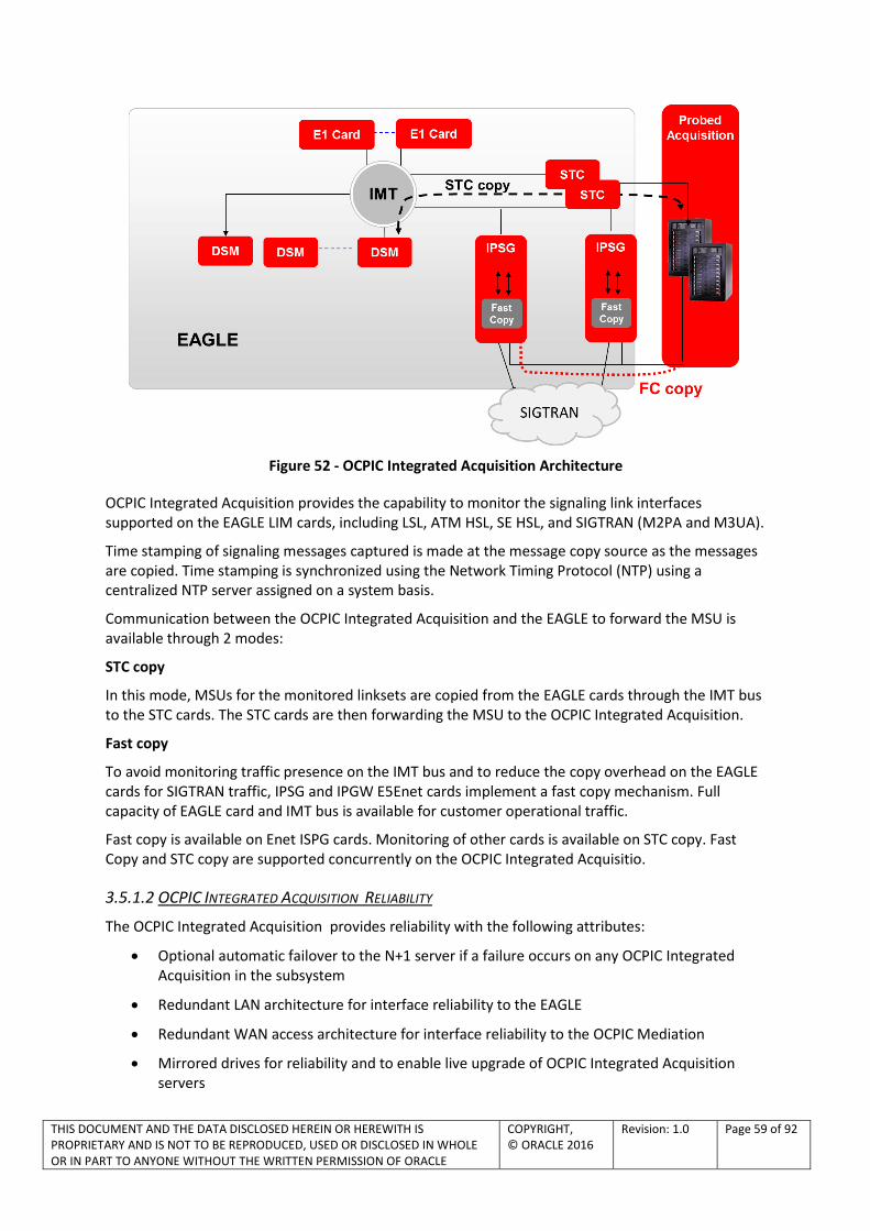
THIS DOCUMENT AND THE DATA DISCLOSED HEREIN OR HEREWITH IS PROPRIETARY AND IS NOT TO BE REPRODUCED, USED OR DISCLOSED IN WHOLE OR IN PART TO ANYONE WITHOUT THE WRITTEN PERMISSION OF ORACLE
COPYRIGHT, © ORACLE 2016
Revision: 1.0 Page 59 of 92
Figure 52 - OCPIC Integrated Acquisition Architecture
OCPIC Integrated Acquisition provides the capability to monitor the signaling link interfaces supported on the EAGLE LIM cards, including LSL, ATM HSL, SE HSL, and SIGTRAN (M2PA and M3UA).
Time stamping of signaling messages captured is made at the message copy source as the messages are copied. Time stamping is synchronized using the Network Timing Protocol (NTP) using a centralized NTP server assigned on a system basis.
Communication between the OCPIC Integrated Acquisition and the EAGLE to forward the MSU is available through 2 modes:
STC copy
In this mode, MSUs for the monitored linksets are copied from the EAGLE cards through the IMT bus to the STC cards. The STC cards are then forwarding the MSU to the OCPIC Integrated Acquisition.
Fast copy
To avoid monitoring traffic presence on the IMT bus and to reduce the copy overhead on the EAGLE cards for SIGTRAN traffic, IPSG and IPGW E5Enet cards implement a fast copy mechanism. Full capacity of EAGLE card and IMT bus is available for customer operational traffic.
Fast copy is available on Enet ISPG cards. Monitoring of other cards is available on STC copy. Fast Copy and STC copy are supported concurrently on the OCPIC Integrated Acquisitio.
3.5.1.2 OCPIC INTEGRATED ACQUISITION RELIABILITY
The OCPIC Integrated Acquisition provides reliability with the following attributes:
Optional automatic failover to the N+1 server if a failure occurs on any OCPIC Integrated Acquisition in the subsystem
Redundant LAN architecture for interface reliability to the EAGLE
Redundant WAN access architecture for interface reliability to the OCPIC Mediation
Mirrored drives for reliability and to enable live upgrade of OCPIC Integrated Acquisition servers

THIS DOCUMENT AND THE DATA DISCLOSED HEREIN OR HEREWITH IS PROPRIETARY AND IS NOT TO BE REPRODUCED, USED OR DISCLOSED IN WHOLE OR IN PART TO ANYONE WITHOUT THE WRITTEN PERMISSION OF ORACLE
COPYRIGHT, © ORACLE 2016
Revision: 1.0 Page 60 of 92
3.5.1.3 OCPIC INTEGRATED ACQUISITION 6H BUFFERING
OCPIC Integrated Acquisition provides buffering and storage of processed signaling information associated with the interface protocol used for secure transfer of the message signaling PDUs to downstream correlation servers thus mitigating WAN outages
When configured on the OCPIC Integrated Acquisition, buffering of signaling data from monitored links for up to 6 hours is performed on the OCPIC Integrated Acquisition in case of network outage. When the outage event is cleared, the buffered data are sent to the OCPIC Mediation for correlation and XDR builder functions. By default the 6h buffering is activated for the MSU and not for IP raw (see IP raw feature section).
If 6h buffering is not required in customer implementation, it is possible to deactivate completely the functionality in the OCPIC Integrated Acquisition. A reduced buffering function (few seconds) is maintained in memory and OCPIC Integrated Acquisition performances are increased.
3.5.1.4 OCPIC INTEGRATED ACQUISITION FILTERING
OCPIC Integrated Acquisition provides filtering capabilities for filtering and discrimination of protocol signaling messages for creation of protocol data flows and data source connections to mediation layer.
All non-relevant frames can be identified and discarded for data flow creation.
OCPIC Integrated Acquisition supports an extended filter capability mode to create very complex filter algorithms.
3.5.1.5 OCPIC INTEGRATED ACQUISITION AUTOMATIC FAILOVER
In order to allow faster recovery and to avoid reconfiguration issue, in case of failure and after all recovery attempts, the system de-allocates the traffic assigned to the failed OCPIC Integrated Acquisition server and reassigns the traffic from the failed OCPIC Integrated Acquisition server. Nominal traffic analysis is restored automatically.
3.5.1.6 OCPIC INTEGRATED ACQUISITION MANAGEMENT
Through the OCPIC Integrated Acquisition integration with the EAGLE, the configuration of the signaling network is discovered and available in the OCPIC central configuration management. This simplifies and provides an error free mechanism to configure the monitoring.
3.5.1.7 OCPIC INTEGRATED ACQUISITION IP RAW AND MSU FORWARDING OPTION
Figure 53 - IP Raw & MSU

THIS DOCUMENT AND THE DATA DISCLOSED HEREIN OR HEREWITH IS PROPRIETARY AND IS NOT TO BE REPRODUCED, USED OR DISCLOSED IN WHOLE OR IN PART TO ANYONE WITHOUT THE WRITTEN PERMISSION OF ORACLE
COPYRIGHT, © ORACLE 2016
Revision: 1.0 Page 61 of 92
By default, the OCPIC Integrated Acquisition is working in MSU forwarding option. Only chunks containing valuable MSU are monitored. This is the best approach to optimize the bandwidth on the customer network and to allow rich set of filtering in the OCPIC Integrated Acquisition. High level SS7 stacks are not impacted and visibility down to the chunk level (M2PA or M3UA) is provided.
If SIGTRAN low layers visibility is requested, with Fast copy, the IP raw option can be activated. In that case, the full IP packet is forwarded to the OCPIC Integrated Acquisition, including all SCTP low layers and management messages. This traffic is used to feed the SIGTRAN low layers builders. It enables in depth troubleshooting for the selected associations and SIGTRAN statistics.
Both modes can be activated simultaneously on the OCPIC Integrated Acquisition server (the IP raw option can be activated per associations).
3.5.1.8 OCPIC INTEGRATED ACQUISITION OPTIONS
2 options are available for integrated acquisition:
For all configurations (including large configurations)
Integrated acquisition is loaded on standard servers installed inside a frame close to the EAGLE. By adding new servers or switches, this frame dedicated to integrated monitoring, allows scalability up to the monitoring of a fully loaded EAGLE.
Figure 54 - EAGLE Frame to Integrated Acquisition connection
For small to medium configuration
For small to medium configuration, the use of a dedicated frame may not be optimized. When configuration allows it, integrated acquisition can be loaded on EAGLE APP-B cards installed inside the EAGLE frame. This option provides several advantages like footprint saving, simplified cabling, no external power supplies (power provided by the EAGLE) and extended life cycle compared to standard servers.
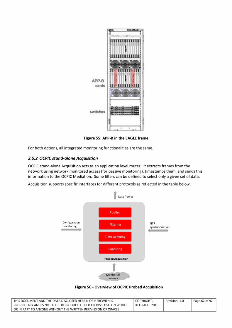
THIS DOCUMENT AND THE DATA DISCLOSED HEREIN OR HEREWITH IS PROPRIETARY AND IS NOT TO BE REPRODUCED, USED OR DISCLOSED IN WHOLE OR IN PART TO ANYONE WITHOUT THE WRITTEN PERMISSION OF ORACLE
COPYRIGHT, © ORACLE 2016
Revision: 1.0 Page 62 of 92
Figure 55: APP-B in the EAGLE frame
For both options, all integrated monitoring functionalities are the same.
3.5.2 OCPIC stand-alone Acquisition
OCPIC stand-alone Acquisition acts as an application level router. It extracts frames from the network using network monitored access (for passive monitoring), timestamps them, and sends this information to the OCPIC Mediation. Some filters can be defined to select only a given set of data.
Acquisition supports specific interfaces for different protocols as reflected in the table below.
Figure 56 - Overview of OCPIC Probed Acquisition

THIS DOCUMENT AND THE DATA DISCLOSED HEREIN OR HEREWITH IS PROPRIETARY AND IS NOT TO BE REPRODUCED, USED OR DISCLOSED IN WHOLE OR IN PART TO ANYONE WITHOUT THE WRITTEN PERMISSION OF ORACLE
COPYRIGHT, © ORACLE 2016
Revision: 1.0 Page 63 of 92
Table 5 - OCPIC Probed Acquisition feature supported matrix
Network Physical layer Network Monitoring Access Signaling transport
SS7 G703 - G704 Through SS7 to SIGTRAN converter
MTP2 Q703
GSM G703 - G704 Through SS7 to SIGTRAN converter
MTP2 Q703
GPRS Gb G703 - G704 Through Gb over E1 to Gb over IP converter
Frame relay
GPRS /UMTS/LTE IP
Ethernet TAP or port mirroring IP
SS7- SE-HSL G703 G704 Through SS7 to SIGTRAN converter
MTP2 Q703
SS7- ATM-HSL G703 – G704 – ATM
Through SS7 to SIGTRAN converter
SAAL
Virtualized Probed Acquisition server:
OCPIC Probed Acquisition server can also be virtualized, using VMware or KVM hypervisor (see section 3.6).
3.5.2.1 FRAME ACQUISITION
Inputs to the OCPIC Acquisition are signaling frames acquired from the network. Output beingframes with timestamps, minus irrelevant data. The primary functions of the Acquisition are:
Time stamping: To ensure timestamp accuracy and particularly the necessary synchronization of the different message feeders distributed all over the network, each must be synchronized by one or several NTP servers
6 hours buffering option for SS7 traffic
Filtering: All non-relevant frames must be identified and discarded. The filters, which consist of any combination of fields, are fully configurable. Arithmetic expressions can also be included. An extension of filters is now available for SIGTRAN (PC, SSN, SIO and GT).
Routing: Frames are routed to the proper mediation processing resource according to configurable routing criteria
3.5.2.2 HSL/LSL TO SIGTRAN CONVERTER
Based on market evolution towards SIGTRAN, Oracle is now proposing to use the HSL/LSL to SIGTRAN converter with OCPIC Probed Acquisition IP to replace HSL/LSL legacy old cards. This solution provides smooth migration path for customer still having legacy links and migrating towards SIGTRAN. All investment made on SIGTRAN are preserved and the high capacity of the converter in a very small foot print provides a very efficient solution for legacy links.
The converter is an external high density box positioned in front of a standard OCPIC Probed Acquisition. It extracts the MSU above the MTP2 layer and codes them inside a M2UA SIGTRAN association. All the layers above MTP2 are preserved. Therefore, the conversion doesn’t impact the upper layers builder visibility.

THIS DOCUMENT AND THE DATA DISCLOSED HEREIN OR HEREWITH IS PROPRIETARY AND IS NOT TO BE REPRODUCED, USED OR DISCLOSED IN WHOLE OR IN PART TO ANYONE WITHOUT THE WRITTEN PERMISSION OF ORACLE
COPYRIGHT, © ORACLE 2016
Revision: 1.0 Page 64 of 92
Figure 57 – LSL/HSL to SIGTRAN Converters
The converter is available for E1 or T1, from 64 to 128 links. High concentration connectivity is achieved through external patch panels (balanced 120 Ω and unbalanced 75 Ω circuits are supported). The converter supports up to 200 LSL (for 64 links option) or 400 LSL (for 128 links option)
Figure 58 – LSL/HSL to SIGTRAN Converters – connectivity
Note that the conversion doesn’t allow low layer builder to compute information like SLOR, Q752… Note: The converter implements troubleshooting tools and counters reports accessible through its own interface. This includes:
Link status: LOS (Loss of Signal), AIS (Alarm Indication Signal), LOF (Loss of Frame), RAI (Remote Alarm Indication) and BPV (Bipolar Violation). Alarms can be generated for link status change.
Counters:
o # Synchronizations down, #Frame errors, #CRC4 errors, #LOS, #AIS, #LOF and #RAI
o ATM counters: #Total Cells, #HEC Errors, #Discarded Cells, #failed Reassemblies, #Forwarded and Discarded Packets.
o HDLC: #Total Packets, #Frame Check Sequence Errors, # Frame Aborted, #Alignment Errors and #Length Errors.
Note that 56Kb/s in E1 LSL is not supported.

THIS DOCUMENT AND THE DATA DISCLOSED HEREIN OR HEREWITH IS PROPRIETARY AND IS NOT TO BE REPRODUCED, USED OR DISCLOSED IN WHOLE OR IN PART TO ANYONE WITHOUT THE WRITTEN PERMISSION OF ORACLE
COPYRIGHT, © ORACLE 2016
Revision: 1.0 Page 65 of 92
3.5.2.3 GB OVER E1 TO GBOIP CONVERTER
As for SS7, Oracle is following network evolution to all IP. Oracle is proposing a front head converter before the OCPIC Probed Acquisition to convert Gb over E1 to Gb over IP. This solution provides smooth migration path for customer still having legacy Gb links and migrating towards IP. All investment made on IP are preserved.
The converter is an external high density box positioned in front of a standard OCPIC Probed Acquisition. It extracts the layers encapsulated in the frame relay PVC and codes them inside Gb over IP path. All the layers above frame relay (including NS/BSSGP) are preserved. Therefore, the conversion doesn’t impact the Gb builder visibility
Figure 59 – Gb over E1 to Gb over IP Converter
The converter is available for 64 or 128 Gb over E1 links. High concentration connectivity is achieved through external patch panels (balanced 120 Ω and unbalanced 75 Ω circuits are supported). The converter supports up to 200 frame relay PVC (for 64 links option) or 400 PVC (for 128 links option)
3.5.2.4 PCAP CAPTURE
With OCPIC, detailed PDU are available for each XDR. But for troubleshooting purpose, it is important sometime to have a capture of the packets captured directly on the wire. The OCPIC Probed Acquisition IP allows Ethereal like capture and storing directly on the probe.
Filters can be defined to extract only the relevant data for the capture. All OCPIC Probed Acquisition filtering rules are applicable including SIGTRAN content filtering. Specifically for SIGTRAN, customer has the capability to capture the IP packets before or after chunk extraction.

THIS DOCUMENT AND THE DATA DISCLOSED HEREIN OR HEREWITH IS PROPRIETARY AND IS NOT TO BE REPRODUCED, USED OR DISCLOSED IN WHOLE OR IN PART TO ANYONE WITHOUT THE WRITTEN PERMISSION OF ORACLE
COPYRIGHT, © ORACLE 2016
Revision: 1.0 Page 66 of 92
Figure 60 – Pcap capture for OCPIC Probed Acquisition
All configuration including start and stop of the capture is controlled through the configuration.
The capture file is created based on standard pcap format (compatible with Ethereal, Wireshark…).
3.5.3 OCDSR Integrated Acquisition
In the OCDSR monitoring case, OCPIC can take benefit of a management link to OCDSR enabling to acquire the configuration tables from OCDSR. This allows OCPIC LTE Diameter xDRs (generic) to be populated with the explicit names of the OCDSR peers equipement which is very convenient for trace and troubleshooting.
This configuration is fully dedicated to OCDSR monitoring and only OCDSR Diameter traffic can be monitored here.
HW configuration is based on Probed Acquisition HW (see §4.2)
PCAP capture (§3.5.2.4) and Acquisition Data Feed (§3.4.2) functions are still valid for OCDSR Integrated Acquisition (OCDSR Diameter traffic only)
OCPIC OCDSR Integrated Acquisition server can also be virtualized, using VMware or KVM hypervisor (see section 3.6).

THIS DOCUMENT AND THE DATA DISCLOSED HEREIN OR HEREWITH IS PROPRIETARY AND IS NOT TO BE REPRODUCED, USED OR DISCLOSED IN WHOLE OR IN PART TO ANYONE WITHOUT THE WRITTEN PERMISSION OF ORACLE
COPYRIGHT, © ORACLE 2016
Revision: 1.0 Page 67 of 92
MME MME MME
OCDSR
Retrieve SCTP/TCP link
IP/node name association
from OC DSR
(e.g. HSS FE)
• OCPIC data record captures source and destination node names, from OCDSR configuration tables,
• Feature deliver enriched data records, on top of the host name (e.g. HSS) captured from the signaling.
• Enables enhanced troubleshooting with peer node name details showing up in Multi-protocol Troubleshooting Application
• Better network performance with e.g. KPIsproviding insight to OCDSR enforcedloadsharing.
OCPIC
Benefits:
• Troubleshooting made easier
• Peer node identification in OCPIC Browser/ Troubleshooting tool
• KPIs supporting peergranularity
HSS
HSS
FE
HSS HSS HSS
HSS
FE
HSS
FE
HSS
FE
HSS
FE
HSS
FEHSS
FE
HSS
FE
Figure 61 – OCDSR Integrated Acquisition

THIS DOCUMENT AND THE DATA DISCLOSED HEREIN OR HEREWITH IS PROPRIETARY AND IS NOT TO BE REPRODUCED, USED OR DISCLOSED IN WHOLE OR IN PART TO ANYONE WITHOUT THE WRITTEN PERMISSION OF ORACLE
COPYRIGHT, © ORACLE 2016
Revision: 1.0 Page 68 of 92
3.6 OCPIC VIRTUALIZED CONFIGURATIONS SUMMARY
Figure 62 summarizes the possible OCPIC Virtualized Configurations for Acquisition, Mediation and Management.
PROBED ACQUISITION,OCDSR INTEGRATED
ACQUISITION
HARDWARE
HYPERVISOR:VMware or KVM
OS TPD 7.0.3
ACQUISITION SW
MEDIATION
HARDWARE
HYPERVISOR:VMware or KVM
OS TPD 7.0.3
MEDIATION SW
MANAGEMENT
HARDWARE
HYPERVISOR (*)
OS ORACLE LINUX 7
MANAGEMENT SW
(*) choice upon customer – not tested by Oracle
Figure 62 – OCPIC Virtualized Configurations Summary
Note: EAGLE Integrated Acquisition Server is not virtualizable.

THIS DOCUMENT AND THE DATA DISCLOSED HEREIN OR HEREWITH IS PROPRIETARY AND IS NOT TO BE REPRODUCED, USED OR DISCLOSED IN WHOLE OR IN PART TO ANYONE WITHOUT THE WRITTEN PERMISSION OF ORACLE
COPYRIGHT, © ORACLE 2016
Revision: 1.0 Page 69 of 92
4 APPENDIX A – OCPIC APPLICATION VS. OCPIC ORACLE LICENCES
The table below provides OCPIC part numbers and legacy names when existing.
Table 6 – OCPIC Part Numbers and Legacy Names
PN Legacy name Oracle licenses Metric
P/N Legacy Name GoForward Name Metric L99456 IMF Oracle Communications Performance Intelligence Center,
Integrated Acquisition Per Server
L99457 IMF Oracle Communications Performance Intelligence Center, Integrated Acquisition
Megabits per Second
L99458 PMF Oracle Communications Performance Intelligence Center, Probed Acquisition
Per Server
L99459 PMF Oracle Communications Performance Intelligence Center, Probed Acquisition
Megabits per Second
L10XXXX PMF Oracle Communications Performance Intelligence Center, OCDSR Acquisition
Server
L104778 PMF Oracle Communications Performance Intelligence Center, OCDSR Acquisition
Megabits per Second
L99460 TADAPT, MSU Feed
Oracle Communications Performance Intelligence Center, Acquisition Data Feed
Per Server
L99465 Data Feed Oracle Communications Performance Intelligence Center, Mediation Data Feed - Server Perpetual
Per Server
L99461 IXP Base Server Oracle Communications Performance Intelligence Center, Mediation Server
Per Server
L99462 XDR builders Oracle Communications Performance Intelligence Center, Mediation Protocol Content: any protocols not listed below
Megabits per Second
L100141 NA Oracle Communications Performance Intelligence Center, Mediation Protocol II Content: Sigtran transport, E-ISUP, GTPv2c Mobility Management, RAN CC2, RAN EMM, RAN ESM, Diameter Gy, Diameter S9
Megabits per Second
L104779 NA Oracle Communications Performance Intelligence Center, Mediation Protocol III Content: LTE Diameter (generic, all Diameter interfaces), LCS, AAA, Sv interface
Megabits per Second
L99466 NSP Oracle Communications Performance Intelligence Center, Management – Simultaneous
Per Simultaneous User
L101850 NA Oracle Communications Technology Foundation for Monitoring Applications
Per Server
L99467 ProTrace Oracle Communications Performance Intelligence Center, Multiprotocol Troubleshooting
Per Simultaneous User
L99468 ProAlarm Oracle Communications Performance Intelligence Center, Network and Service Alarm
Per Simultaneous User
L100213 ProPerf Oracle Communications Performance Intelligence Center, Network and Service Dashboard NOTE: only up to OCPIC 10.1.x
Per Management Server
L104780 Properf Oracle Communications Performance Intelligence Center, Dashboard NOTE : only from OCPIC 10.2+, replaces L100213 from 10.2
Per Management Server
L99470 ProDiag, Oracle Communications Performance Intelligence Center, Per Simultaneous

THIS DOCUMENT AND THE DATA DISCLOSED HEREIN OR HEREWITH IS PROPRIETARY AND IS NOT TO BE REPRODUCED, USED OR DISCLOSED IN WHOLE OR IN PART TO ANYONE WITHOUT THE WRITTEN PERMISSION OF ORACLE
COPYRIGHT, © ORACLE 2016
Revision: 1.0 Page 70 of 92
ProDiag SIGTRAN
SS7 Network Surveillance User
L101850 NA Oracle Communications Technology Foundation for Monitoring Applications - per Server Perpetual
Per Server

THIS DOCUMENT AND THE DATA DISCLOSED HEREIN OR HEREWITH IS PROPRIETARY AND IS NOT TO BE REPRODUCED, USED OR DISCLOSED IN WHOLE OR IN PART TO ANYONE WITHOUT THE WRITTEN PERMISSION OF ORACLE
COPYRIGHT, © ORACLE 2016
Revision: 1.0 Page 71 of 92
5 APPENDIX B –ACRONYMS
This section defines the specific terms, acronyms, and abbreviations used in this document.
Table 7– List of acronyms
Acronym Definition
A Interface the GSM interface between a BSS and an MSC
AIN advanced intelligent network
AMA automatic message accounting
ANSI American National Standards Institute
API application programming interface
ARPU Average Revenue Per User
ASCII American standard code for information interchange
ASR answer seizure ratio
ATM asynchronous transfer mode
BCD binary coded decimal
B-G Interfaces all GSM interfaces that use the MAP protocol
BHC base hardware configuration
BIB backward indicator bit
BNS billing number services
BSC base station controller
BSN backward sequence number
BSS GSM base station subsystem
BSSMAP GSM base station subsystem mobile application part
CDMA code division multiple access
CDR call detail record
CIC ISUP circuit identification code
CIMD2 Computer Interface to Message Distribution 2, Nokia
CLLI common language location identifier
CMISE common management information service element
CORBA common object request broker architecture
CPN called party number
CR an SCCP connection request message
CRC cyclic redundancy check
CSFB Circuit Switched Fallback
DCM data communication module cards
DIR direction, transmit or receive
DTAP GSM direct transfer application part
ECM enhanced communications module
EECM Ethernet enhanced communications module
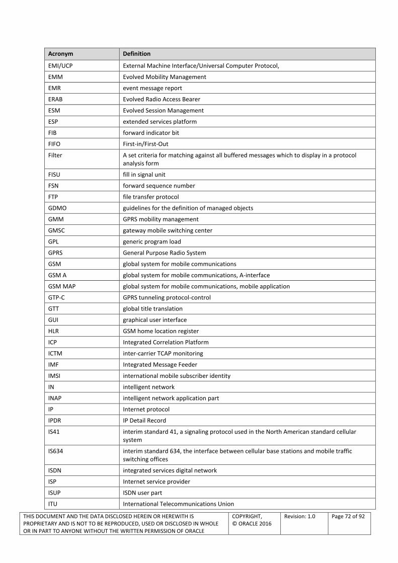
THIS DOCUMENT AND THE DATA DISCLOSED HEREIN OR HEREWITH IS PROPRIETARY AND IS NOT TO BE REPRODUCED, USED OR DISCLOSED IN WHOLE OR IN PART TO ANYONE WITHOUT THE WRITTEN PERMISSION OF ORACLE
COPYRIGHT, © ORACLE 2016
Revision: 1.0 Page 72 of 92
Acronym Definition
EMI/UCP External Machine Interface/Universal Computer Protocol,
EMM Evolved Mobility Management
EMR event message report
ERAB Evolved Radio Access Bearer
ESM Evolved Session Management
ESP extended services platform
FIB forward indicator bit
FIFO First-in/First-Out
Filter A set criteria for matching against all buffered messages which to display in a protocol analysis form
FISU fill in signal unit
FSN forward sequence number
FTP file transfer protocol
GDMO guidelines for the definition of managed objects
GMM GPRS mobility management
GMSC gateway mobile switching center
GPL generic program load
GPRS General Purpose Radio System
GSM global system for mobile communications
GSM A global system for mobile communications, A-interface
GSM MAP global system for mobile communications, mobile application
GTP-C GPRS tunneling protocol-control
GTT global title translation
GUI graphical user interface
HLR GSM home location register
ICP Integrated Correlation Platform
ICTM inter-carrier TCAP monitoring
IMF Integrated Message Feeder
IMSI international mobile subscriber identity
IN intelligent network
INAP intelligent network application part
IP Internet protocol
IPDR IP Detail Record
IS41 interim standard 41, a signaling protocol used in the North American standard cellular system
IS634 interim standard 634, the interface between cellular base stations and mobile traffic switching offices
ISDN integrated services digital network
ISP Internet service provider
ISUP ISDN user part
ITU International Telecommunications Union

THIS DOCUMENT AND THE DATA DISCLOSED HEREIN OR HEREWITH IS PROPRIETARY AND IS NOT TO BE REPRODUCED, USED OR DISCLOSED IN WHOLE OR IN PART TO ANYONE WITHOUT THE WRITTEN PERMISSION OF ORACLE
COPYRIGHT, © ORACLE 2016
Revision: 1.0 Page 73 of 92
Acronym Definition
KPI Key Performance Indicator
KQI Key Quality Indicator
LAN local area network
LATA local access transport area
LAP-B link access procedure-balanced
LEC local exchange carrier
LIC link interface card – The LIC is a processor card of the i2000 hardware shelf. Every appliqué in the i2000 resides on an LIC. The term LIC may refer to any of the following PCBAs: the 8Mhz LIC, the 16Mhz LIC, or the 32Mhz 486 LIC or “ALICE”.
LIDB Line information database
LIM link interface modules
LNP local number portability
LTE Long Term Evolution
LUP location update
M2PA MTP2 user peer-to-peer adaptation layer
M3PA MTP3 user peer-to-peer adaptation layer
M2UA MTP2 User Adaptation Layer
M3UA MTP3 User Adaptation Layer
MAP GSM mobile application part
MBS message buffer server
MGCP media gateway control protocol
MIB managed information base
MIT managed information tree
MMC mobile-to-mobile call
MO managed object
MOC mobile-originated call
MS mobile station
MSC mobile switching center
MSISDN mobile-station ISDN number
MSU message signal unit
MT message type
MTC mobile-terminated call
MTP message transfer part – message transaction part that provides functions for basic routing of signaling messages between signaling points
NAS Non Access Stratum
NEBS network equipment building standards
NFS network file system
NMS network management system
NNM HP OpenView Network Node Manager
NOC network operations center
NOCC network operation control center

THIS DOCUMENT AND THE DATA DISCLOSED HEREIN OR HEREWITH IS PROPRIETARY AND IS NOT TO BE REPRODUCED, USED OR DISCLOSED IN WHOLE OR IN PART TO ANYONE WITHOUT THE WRITTEN PERMISSION OF ORACLE
COPYRIGHT, © ORACLE 2016
Revision: 1.0 Page 74 of 92
Acronym Definition
NPLT network performance load test
NTP network time protocol
NUP network user part
OAM&P operations administration maintenance and provisioning
OCS Online Charging System
OCDSR Oracle Communications Diameter Signalling Router
ODS operational data store
OFCS Offline Charging system
OPC origination point code
OSI open system interconnection
PA Protocol Analysis
PCC Policy & Charging Rule
PCI peripheral component interconnect
PCM Pulse Coded Modulation
PCS personal communications service
PDF Protocol Definition File
PDN Packet Data Network
PDU protocol data unit
PDR Peg Count Data Record
PGW PDN GateWay
PLMN Public Land Mobile Network
OCPIC Probed Acquisition (PMF)
Probed Message Feeder
PSTN public switched telephone network
QoS Quality of Service
RAM random access memory
RMS RackMount Server
ROI return on investment
SAS signaling application system
SCCP signaling connection control part
SCP service control point
SCP/AP service control point/application part
SCSI small computer system interface
SCTP simple control transmission protocol
SDP session description protocol
SDR Session Detail Record
SGW Service GateWay
SI MTP service indicator
SIP session initiation protocol
SLA Service Level Agreement

THIS DOCUMENT AND THE DATA DISCLOSED HEREIN OR HEREWITH IS PROPRIETARY AND IS NOT TO BE REPRODUCED, USED OR DISCLOSED IN WHOLE OR IN PART TO ANYONE WITHOUT THE WRITTEN PERMISSION OF ORACLE
COPYRIGHT, © ORACLE 2016
Revision: 1.0 Page 75 of 92
Acronym Definition
SLR SCCP source local reference
SLTM/SLTA signaling link test message/signaling link test acknowledge
SMPP Short Message Peer to Peer
SMS Short Message Service
SMS-C Short Message Service Center
SNAP signaling node application platform
SNMP simple network management protocol
SP signaling point
SQL structured query language
SS7 Signaling system number 7 provides two key abilities: fast-call setup via high-speed circuit-switched connections and transactions capabilities that deal with remote data base interactions
SSN SCCP subsystem number
SSP service switching point
STC Oracle)
STP signal transfer point
SU signaling unit
SUA SCCP user adaptation layer
TAC technical assistance center
TA Tracking Area
TCAP transaction capabilities application part
TCP transmission control protocol
TCP/IP transmission control protocol/Internet protocol
TDR Transaction Detail Record
TID TCAP transaction ID
TMN telecommunications management network
TMSI temporary mobile subscriber identity
TGN trunk group number
TUP telephone user part
UE User Equipment
UDM user defined message
VoIP Voice over IP
VoLTE Voice Over LTE
VLR Visitor Location Register
VPN Virtual Private Network
WAN wide area network
WWW World Wide Web
XDR x Detail Record (Call, Transaction...)
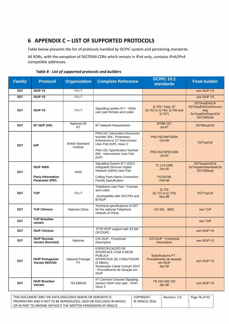
THIS DOCUMENT AND THE DATA DISCLOSED HEREIN OR HEREWITH IS PROPRIETARY AND IS NOT TO BE REPRODUCED, USED OR DISCLOSED IN WHOLE OR IN PART TO ANYONE WITHOUT THE WRITTEN PERMISSION OF ORACLE
COPYRIGHT, © ORACLE 2016
Revision: 1.0 Page 76 of 92
6 APPENDIX C – LIST OF SUPPORTED PROTOCOLS
Table below presents the list of protocols handled by OCPIC system and pertaining standards.
All XDRs, with the exception of SIGTRAN CDRs which remain in IPv4 only, contains IPv6/IPv4 compatible addresses.
Table 8 - List of supported protocols and builders
Family Protocol Organization Complete Reference OCPIC 10.2 standards
Final builder
SS7 ISUP V1 ITU-T see ISUP V3
SS7 ISUP V2 ITU-T see ISUP V3
SS7 ISUP V3 ITU-T Signalling system N°7 - ISDN user part formats and codes
Q.763 / Sept_97 (Q.761 to Q.764, Q.766 and
Q.767)
SS7IsupEtsiCdr SS7IsupEtsiSudrAccoun
ting Ss7IsupEtsiSuperCdr
SS7UMSudr
SS7 BT NUP (UK) National UK
BT BT Network Requirement
BTNR 167 Jul-87
SS7BtnupCdr
SS7 IUP British Standard
Institute
PNO-ISC Information Document Number 004 - Proprietary Extensions to C7 Interconnect User Part (IUP), Issue 2
PNO-ISC/INFO/004 Oct-99
SS7IupCdr
PNO-ISC Specification Number 006 - Interconnect User Part (IUP)
PNO-ISC/SPEC/006 Jul-00
SS7
ISUP ANSI
ANSI
Signalling System N°7 (SS7) - Integrated Services Digital Network (ISDN) User Part
T1.113-1995 Jun-05
SS7IsupAnsiCdr Ss7IsupAnsiSentinelCdr
SS7UMSudr
Party Information Parameter (PIP)
Calling Party Name Convention Facility Specification
TICO076E Feb-98
SS7 TUP ITU-T
Telephone User Part - Formats and codes
Incompatible with SSUTR2 and BTNUP
Q.723 (Q.721 to Q.725)
Nov-88 SS7TupCdr
SS7 TUP Chinese National China Technical specifications of SS7 for the national Telephone network of China
GF 001 - 9001 see TUP
SS7 TUP Brasilian variant
see TUP
SS7 ISUP Chinese ETSI ISUP support with 24 bits OPC/DPC
see ISUP V3
SS7 ISUP Russian Variant (Sovintel)
National CIS ISUP - Functional Description
CIS ISUP - Functional Description
see ISUP V3
SS7 ISUP Portuguese Variant (NOVIS)
National Portugal PT
ESPECIFICAÇÃO DE INTERFACE COM A REDE PÚBLICA INTERFACE DE COMUTADOR (2 Mbit/s) Sinalização Canal Comum SS#7 - Procedimento de taxação em ISUP
Spécifications PT - Procedimento de taxação
em ISUP Apr-99
see ISUP V3
SS7 ISUP Brasilian Variant
TELEBRAS #7 Common Channel Signaling System ISDN User part - ISUP, Issue 3
TB 220-250-732 Apr-98
see ISUP V3

THIS DOCUMENT AND THE DATA DISCLOSED HEREIN OR HEREWITH IS PROPRIETARY AND IS NOT TO BE REPRODUCED, USED OR DISCLOSED IN WHOLE OR IN PART TO ANYONE WITHOUT THE WRITTEN PERMISSION OF ORACLE
COPYRIGHT, © ORACLE 2016
Revision: 1.0 Page 77 of 92
Family Protocol Organization Complete Reference OCPIC 10.2 standards
Final builder
SS7 ISUP Colombian Variant
Ministerio des Comunicaciones
Norma Nacional de Señalizacion por Canal Comun N.°7 - SCC7
Norma Nacional Apr-98
see ISUP V3
SS7 ISUP Mexican Variant
Telmex
E-801.04 Sepcification - Integrated Services Degital Network user Part (ISUP), Edition "C-3"
E-801.04 Dec-97
see ISUP V3
SS7 ISUP Argentina variant
Telefonica Argentina
RDSI User Part Specification Signaling System N°7
General Specification AR.EG.s1.002 Ed 1
corrected see ISUP V3
SS7
Cisco E-ISUP Cisco EISUP Specification - Cisco Systems
Cisco ENG-46168 Release 44
SS7_EISUP_CDR
IETF Reliable UDP Protocol draft-ietf-sigtran-reliable-
udp-00.txt Feb-1999
SS7 LSSU ITU-T Signalling link Q.703 Jul-96
SS7 MTP ITU-T Level 2 & 3
ITU-T Functional description of the Message Transfer Part (MTP) of Signalling System No. 7
Q.701 Mar-93
SS7L2L3EtsiSudr SS7Q752EtsiStats
Signalling link Q.703 / Q.704
Jul-96
SS7 MTP ANSI Level 2 & 3
ANSI Signalling System N°7 - Message Transfer Part (MTP)
T1.111-1996 Mar-96
SS7L2L3AnsiSudr
SS7 SCCP ITU-T ITU-T Signalling connection control part formats and codes
Q.713 Jul-96
Ss7SccpSuaSudr
SS7 SCCP ANSI ANSI Signalling System Number 7 - Signalling Connection Control Part (SCCP)
T1.112-1996 Jan-96
Ss7SccpSuaSudr
SS7 TCAP (MAP & INAP support)
ITU-T Transaction capabilities formats and encoding
Q.773 Jun-97
SS7
TCAP (IS-41 support)
ANSI Signalling System Number 7 (SS7) - Transaction Capabilities Application Part (TCAP)
T1.114-1996 Mar-96
ANSI Signalling System Number 7 (SS7) - Transaction Capabilities Application Part (TCAP)
T1.114-2000 Jun-00
SS7 INAP Siemens Specific: Siemens Siemens Core INAP P30308-A7128-A120-01-
7659 May-98
SS7InapSudrAccounting SS7InapTdr
SS7_INAP_Compact_TDR
SS7
INAP CS1 ETSI
Intelligent Network (IN); Intelligent Network Capability Set 1 (CS1); Core Intelligent Network Application Protocol (INAP);
ETS 300 374-1 Sep-94
SS7InapSudrAccounting SS7InapTdr
SS7_INAP_Compact_TDR
ITU-T Introduction to intelligent network capability set 1
ITU-T Q.1211 Mar-93
ITU-T Distributed functional plane for intelligent network CS-1
ITU-T Q.1214 Oct-95
ITU-T Interface Recommendation for intelligent network CS-1
ITU-T Q.1218 Oct-95
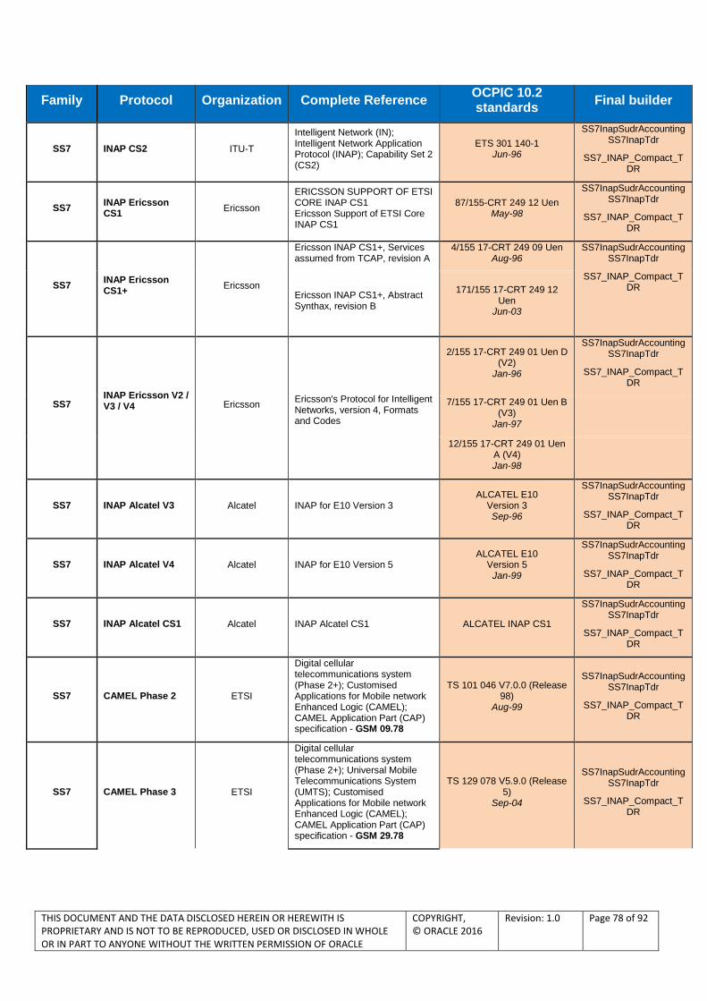
THIS DOCUMENT AND THE DATA DISCLOSED HEREIN OR HEREWITH IS PROPRIETARY AND IS NOT TO BE REPRODUCED, USED OR DISCLOSED IN WHOLE OR IN PART TO ANYONE WITHOUT THE WRITTEN PERMISSION OF ORACLE
COPYRIGHT, © ORACLE 2016
Revision: 1.0 Page 78 of 92
Family Protocol Organization Complete Reference OCPIC 10.2 standards
Final builder
SS7 INAP CS2 ITU-T
Intelligent Network (IN); Intelligent Network Application Protocol (INAP); Capability Set 2 (CS2)
ETS 301 140-1 Jun-96
SS7InapSudrAccounting SS7InapTdr
SS7_INAP_Compact_TDR
SS7 INAP Ericsson CS1
Ericsson
ERICSSON SUPPORT OF ETSI CORE INAP CS1 Ericsson Support of ETSI Core INAP CS1
87/155-CRT 249 12 Uen May-98
SS7InapSudrAccounting SS7InapTdr
SS7_INAP_Compact_TDR
SS7 INAP Ericsson CS1+
Ericsson
Ericsson INAP CS1+, Services assumed from TCAP, revision A
4/155 17-CRT 249 09 Uen Aug-96
SS7InapSudrAccounting SS7InapTdr
SS7_INAP_Compact_TDR
Ericsson INAP CS1+, Abstract Synthax, revision B
171/155 17-CRT 249 12 Uen
Jun-03
SS7 INAP Ericsson V2 / V3 / V4 Ericsson
Ericsson's Protocol for Intelligent Networks, version 4, Formats and Codes
2/155 17-CRT 249 01 Uen D (V2)
Jan-96
SS7InapSudrAccounting SS7InapTdr
SS7_INAP_Compact_TDR
7/155 17-CRT 249 01 Uen B (V3)
Jan-97
12/155 17-CRT 249 01 Uen A (V4) Jan-98
SS7 INAP Alcatel V3 Alcatel INAP for E10 Version 3 ALCATEL E10
Version 3 Sep-96
SS7InapSudrAccounting SS7InapTdr
SS7_INAP_Compact_TDR
SS7 INAP Alcatel V4 Alcatel INAP for E10 Version 5 ALCATEL E10
Version 5 Jan-99
SS7InapSudrAccounting SS7InapTdr
SS7_INAP_Compact_TDR
SS7 INAP Alcatel CS1 Alcatel INAP Alcatel CS1 ALCATEL INAP CS1
SS7InapSudrAccounting SS7InapTdr
SS7_INAP_Compact_TDR
SS7 CAMEL Phase 2 ETSI
Digital cellular telecommunications system (Phase 2+); Customised Applications for Mobile network Enhanced Logic (CAMEL); CAMEL Application Part (CAP) specification - GSM 09.78
TS 101 046 V7.0.0 (Release 98)
Aug-99
SS7InapSudrAccounting SS7InapTdr
SS7_INAP_Compact_TDR
SS7 CAMEL Phase 3 ETSI
Digital cellular telecommunications system (Phase 2+); Universal Mobile Telecommunications System (UMTS); Customised Applications for Mobile network Enhanced Logic (CAMEL); CAMEL Application Part (CAP) specification - GSM 29.78
TS 129 078 V5.9.0 (Release 5)
Sep-04
SS7InapSudrAccounting SS7InapTdr
SS7_INAP_Compact_TDR
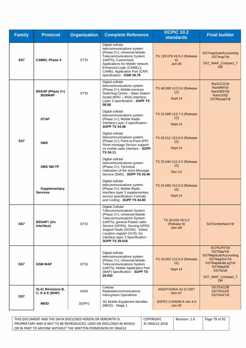
THIS DOCUMENT AND THE DATA DISCLOSED HEREIN OR HEREWITH IS PROPRIETARY AND IS NOT TO BE REPRODUCED, USED OR DISCLOSED IN WHOLE OR IN PART TO ANYONE WITHOUT THE WRITTEN PERMISSION OF ORACLE
COPYRIGHT, © ORACLE 2016
Revision: 1.0 Page 79 of 92
Family Protocol Organization Complete Reference OCPIC 10.2 standards
Final builder
SS7 CAMEL Phase 4 ETSI
Digital cellular telecommunications system (Phase 2+); Universal Mobile Telecommunications System (UMTS); Customised Applications for Mobile network Enhanced Logic (CAMEL); CAMEL Application Part (CAP) specification - GSM 29.78
TS 129 078 V6.5.0 (Release 6)
Jun-06
SS7InapSudrAccounting SS7InapTdr
SS7_INAP_Compact_TDR
SS7
BSSAP (Phase 2+) BSSMAP
ETSI
Digital cellular telecommunications system (Phase 2+); Mobile-services Switching Centre – Base Station Systel (MSC – BSS) interface; Layer 3 specification - 3GPP TS 08.08
TS 48.008 V12.0.0 (Release 12)
Sept-14
RanCC2Cdr RanMMTdr RanSMSTdr RanUSSD
SS7BssapTdr
DTAP
Digital cellular telecommunications system (Phase 2+); Mobile Radio Interface;Layer 3 specification - 3GPP TS 04.08
TS 24.008 V12.7.0 (Release 12)
Sept-14
SMS
Digital cellular telecommunications system (Phase 2+); Point-to-Point (PP) Short message Service support on mobile radio interface - 3GPP TS 04.11
TS 24.011 V12.0.0 (Release 12)
Sept-14
SMS SM-TP
Digital cellular telecommunications system (Phase 2+); Technical realization of the short Message Service (SMS) - 3GPP TS 03.40
TS 23.040 V12.2.0 (Release 12)
Dec-14
Supplementary Services
Digital cellular telecommunications system (Phase 2+); Mobile Radio interface layer 3 supplementary service specification; Formats and Coding - 3GPP TS 04.80
TS 24.080 V12.0.0 (Release 12)
Sept-14
SS7 BSSAP+ (Gs Interface)
ETSI
Digital Cellular Telecommunications System (Phase 2+); Universal Mobile Telecommunications System (UMTS); general Packet radio Service (GPRS); Serving GPRS Support Node (SGSN) - Visitor Location register (VLR); Gs Interface layer 3 Specification - 3GPP TS 29.018
TS 29.018 V6.5.0 (Release 6)
Dec-06 Ss7GsInterfaceTdr
SS7 GSM MAP ETSI
Digital cellular telecommunications system (Phase 2+); Universal Mobile Telecommunications System (UMTS); Mobile Application Part (MAP) specification - 3GPP TS 29.002
TS 29.002 V12.6.0 (Release 12)
Sept-14
Ss7HLRVTdr SS7MapTdr
SS7MapSudrAccounting SS7MapSmTdr
SS7MapMultiLegTdr SS7MapDB SS7Smdr
SS7_MAP_Compact_TDR
SS7
IS-41 Révisions B, C, D & E (MAP)
ANSI Cellular Radiotelecommunications Intersystem Operations
ANSI/TIA/EIA-41-D-1997 Nov-97
SS7IS41DB SS7IS41DE SS7IS41Tdr
MEID 3GPP2 3G Mobile Equipment identifier (MEID) - Stage 1
3GPP2 S.R0048-A Ver 4.0 Jun-05
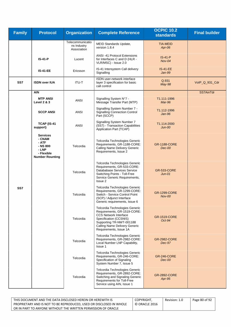
THIS DOCUMENT AND THE DATA DISCLOSED HEREIN OR HEREWITH IS PROPRIETARY AND IS NOT TO BE REPRODUCED, USED OR DISCLOSED IN WHOLE OR IN PART TO ANYONE WITHOUT THE WRITTEN PERMISSION OF ORACLE
COPYRIGHT, © ORACLE 2016
Revision: 1.0 Page 80 of 92
Family Protocol Organization Complete Reference OCPIC 10.2 standards
Final builder
Telecommunications Industry Association
MEID Standards Update, version 1.8.4
TIA-MEID Apr-06
IS-41-P Lucent ANSI -41 Protocol Extensions for Interfaces C and D (HLR - VLR/MSC) - Issue 2.0
IS-41-P Nov-04
IS-41-EE Ericsson IS-41 Intersystem Call delivery Signalling
IS-41-EE Jan-99
SS7 ISDN over IUA ITU-T ISDN user-network interface layer 3 specification for basic call control
Q.931 May-98
VoIP_Q_931_Cdr
SS7
AIN SS7AinTdr
MTP ANSI Level 2 & 3
ANSI Signalling System N°7 - Message Transfer Part (MTP)
T1.111-1996 Mar-96
SCCP ANSI ANSI Signalling System Number 7 - Signalling Connection Control Part (SCCP)
T1.112-1996 Jan-96
TCAP (IS-41 support)
ANSI Signalling System Number 7 (SS7) - Transaction Capabilities Application Part (TCAP)
T1.114-2000 Jun-00
Services - CNAM - ATF - NS 800 - LNP - Flexible Number Rounting
Telcordia
Telcordia Technologies Generic Requirements, GR-1188-CORE: Calling Name Delivery Generic Requirements, Issue 2
GR-1188-CORE Dec-00
Telcordia
Telcordia Technologies Generic Requirements, GR-533-CORE: Datababase Services Service Switching Points - Toll-Free Service Generic Requirements, Issue 2
GR-533-CORE Jun-01
Telcordia
Telcordia Technologies Generic Requirements, GR-1299-CORE: Switch - Service Control Point (SCP) / Adjunct Interface Generic requirements, Issue 6
GR-1299-CORE Nov-00
Telcordia
Telcordia Technologies Generic Requirements, GR-1519-CORE: CCS Network Interface Specification (CCSNIS) Supporting TR-NWT-001188 Calling Name Delivery Generic Requirements, Issue 1A
GR-1519-CORE Oct-94
Telcordia
Telcordia Technologies Generic Requirements, GR-2982-CORE: Local Number LNP Capability, Issue 1
GR-2982-CORE Dec-97
Telcordia
Telcordia Technologies Generic Requirements, GR-246-CORE: Specification of Signaling System Number 7, Issue 5
GR-246-CORE Dec-00
Telcordia
Telcordia Technologies Generic Requirements, GR-2892-CORE: Switching and Signaling Generic Requirements for Toll-Free Service using AIN, Issue 1
GR-2892-CORE Apr-95

THIS DOCUMENT AND THE DATA DISCLOSED HEREIN OR HEREWITH IS PROPRIETARY AND IS NOT TO BE REPRODUCED, USED OR DISCLOSED IN WHOLE OR IN PART TO ANYONE WITHOUT THE WRITTEN PERMISSION OF ORACLE
COPYRIGHT, © ORACLE 2016
Revision: 1.0 Page 81 of 92
Family Protocol Organization Complete Reference OCPIC 10.2 standards
Final builder
SS7 LIDB Telcordia
Telcordia Technologies Generic Requirements, GR-1158-CORE : OSSGR Section 22.3: Line Information Database, Issue 4
GR-1158-CORE Dec-00
SS7LidbTdr
Telcordia Technologies Generic Requirements, GR-1149-CORE - OSSGR Section 10: System Interfaces, Issue 6
GR-1149-CORE Sep-06
SS7 CLASS Telcordia
Telcordia Technologies Generic Requirements, GR-1188-CORE: Calling Name Delivery Generic Requirements, Issue 2
GR-1188-CORE Dec-00
SS7ClassTdr
Telcordia Technologies Generic Requirements, GR-215-CORE: LSSGR: CLASS Feature: Automatic Callback (FSD 01-02-1250), Issue 2
GR-215-CORE Apr-02
Telcordia Technologies Generic Requirements, GR-220-CORE: LSSGR: CLASS Feature: Screening List Editing (FSD 30-28-0000), Issue 2
GR-220-CORE Apr-02
Telcordia Technologies Generic Requirements, GR-227-CORE: LSSGR: CLASS Feature: Automatic Recall (FSD 01-02-1260), Issue 2
GR-227-CORE Apr-02
SS7
WIN Services Telcordia Wireless Intelligent Network EIA/TIA IS-771
Jul-99 SS7WinServiceTdr
IS-771 Telcordia Wireless Intelligent Network - Addendum 1
EIA/TIA IS-771 Aug-01
Telcordia
Cellular Radiotelecommunications ntersystem Operations, Revision B to E
EIS/TIA IS-41 Nov-97
3GPP2 Win Phase 1, Version 1.0 3GPP2 N.S0013-0
Dec-98
3GPP2 Win Phase 2, Version 1.0 3GPP2 N.S0004-0
Apr-01
3GPP2 ANSI -41-D Miscellaneous Enhancements, Version 1.0.0, Revision 0
3GPP2 N.S0015 Jan-00
IS-826 Telcordia Wireless Intelligent Network Capabilities for pre-paid Charging
TIA/EIA/IS-826 (1 to 7) Aug-00
J-STD-036B ANSI Enhanced Wireless SP-3-3890-RV2 9-1-1 Phase II
J-STD-036-B Jan-08
IS-843 Telecommunicatio
ns Industry Association
Wireless Intelligent network Support for Location Based Services
TIA-843 Aug-04
IS-801 Telecommunicatio
ns Industry Association
Position Determination Service for cdma2000 Spread Spectrum Systems
TIA-801-A Apr-04
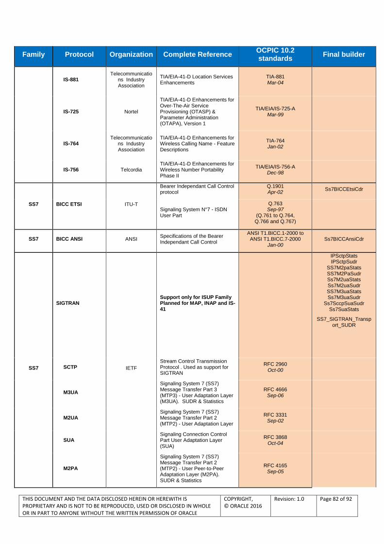
THIS DOCUMENT AND THE DATA DISCLOSED HEREIN OR HEREWITH IS PROPRIETARY AND IS NOT TO BE REPRODUCED, USED OR DISCLOSED IN WHOLE OR IN PART TO ANYONE WITHOUT THE WRITTEN PERMISSION OF ORACLE
COPYRIGHT, © ORACLE 2016
Revision: 1.0 Page 82 of 92
Family Protocol Organization Complete Reference OCPIC 10.2 standards
Final builder
IS-881 Telecommunicatio
ns Industry Association
TIA/EIA-41-D Location Services Enhancements
TIA-881 Mar-04
IS-725 Nortel
TIA/EIA-41-D Enhancements for Over-The-Air Service Provisioning (OTASP) & Parameter Administration (OTAPA), Version 1
TIA/EIA/IS-725-A Mar-99
IS-764 Telecommunicatio
ns Industry Association
TIA/EIA-41-D Enhancements for Wireless Calling Name - Feature Descriptions
TIA-764 Jan-02
IS-756 Telcordia TIA/EIA-41-D Enhancements for Wireless Number Portability Phase II
TIA/EIA/IS-756-A Dec-98
SS7 BICC ETSI ITU-T
Bearer Independant Call Control protocol
Q.1901 Apr-02
Ss7BICCEtsiCdr
Signaling System N°7 - ISDN User Part
Q.763 Sep-97
(Q.761 to Q.764, Q.766 and Q.767)
SS7 BICC ANSI ANSI Specifications of the Bearer Independant Call Control
ANSI T1.BICC.1-2000 to ANSI T1.BICC.7-2000
Jan-00 Ss7BICCAnsiCdr
SS7
SIGTRAN
IETF
Support only for ISUP Family Planned for MAP, INAP and IS-41
IPSctpStats IPSctpSudr
SS7M2paStats SS7M2PaSudr Ss7M2uaStats Ss7M2uaSudr SS7M3uaStats Ss7M3uaSudr
Ss7SccpSuaSudr Ss7SuaStats
SS7_SIGTRAN_Transport_SUDR
SCTP Stream Control Transmission Protocol . Used as support for SIGTRAN
RFC 2960 Oct-00
M3UA
Signaling System 7 (SS7) Message Transfer Part 3 (MTP3) - User Adaptation Layer (M3UA). SUDR & Statistics
RFC 4666 Sep-06
M2UA Signaling System 7 (SS7) Message Transfer Part 2 (MTP2) - User Adaptation Layer
RFC 3331 Sep-02
SUA Signaling Connection Control Part User Adaptation Layer (SUA)
RFC 3868 Oct-04
M2PA
Signaling System 7 (SS7) Message Transfer Part 2 (MTP2) - User Peer-to-Peer Adaptation Layer (M2PA). SUDR & Statistics
RFC 4165 Sep-05
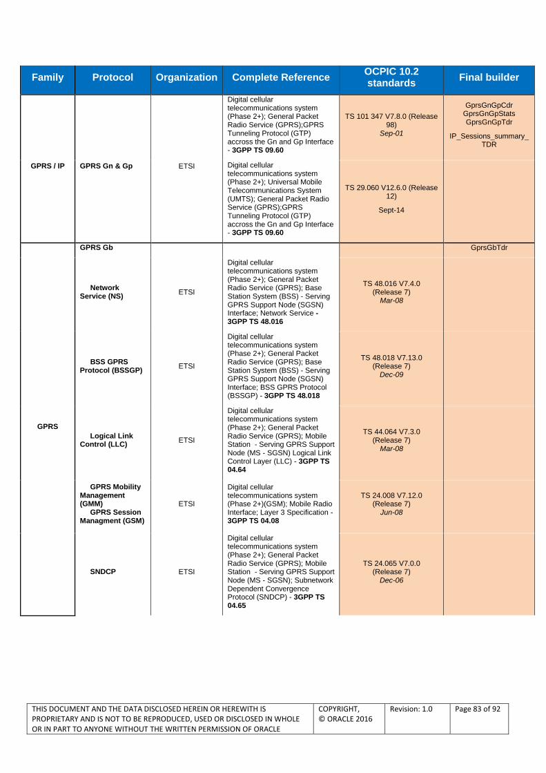
THIS DOCUMENT AND THE DATA DISCLOSED HEREIN OR HEREWITH IS PROPRIETARY AND IS NOT TO BE REPRODUCED, USED OR DISCLOSED IN WHOLE OR IN PART TO ANYONE WITHOUT THE WRITTEN PERMISSION OF ORACLE
COPYRIGHT, © ORACLE 2016
Revision: 1.0 Page 83 of 92
Family Protocol Organization Complete Reference OCPIC 10.2 standards
Final builder
GPRS / IP GPRS Gn & Gp ETSI
Digital cellular telecommunications system (Phase 2+); General Packet Radio Service (GPRS);GPRS Tunneling Protocol (GTP) accross the Gn and Gp Interface - 3GPP TS 09.60
TS 101 347 V7.8.0 (Release 98)
Sep-01
GprsGnGpCdr GprsGnGpStats GprsGnGpTdr
IP_Sessions_summary_TDR
Digital cellular telecommunications system (Phase 2+); Universal Mobile Telecommunications System (UMTS); General Packet Radio Service (GPRS);GPRS Tunneling Protocol (GTP) accross the Gn and Gp Interface - 3GPP TS 09.60
TS 29.060 V12.6.0 (Release 12)
Sept-14
GPRS
GPRS Gb GprsGbTdr
Network Service (NS)
ETSI
Digital cellular telecommunications system (Phase 2+); General Packet Radio Service (GPRS); Base Station System (BSS) - Serving GPRS Support Node (SGSN) Interface; Network Service - 3GPP TS 48.016
TS 48.016 V7.4.0 (Release 7)
Mar-08
BSS GPRS Protocol (BSSGP)
ETSI
Digital cellular telecommunications system (Phase 2+); General Packet Radio Service (GPRS); Base Station System (BSS) - Serving GPRS Support Node (SGSN) Interface; BSS GPRS Protocol (BSSGP) - 3GPP TS 48.018
TS 48.018 V7.13.0 (Release 7)
Dec-09
Logical Link Control (LLC)
ETSI
Digital cellular telecommunications system (Phase 2+); General Packet Radio Service (GPRS); Mobile Station - Serving GPRS Support Node (MS - SGSN) Logical Link Control Layer (LLC) - 3GPP TS 04.64
TS 44.064 V7.3.0 (Release 7)
Mar-08
GPRS Mobility Management (GMM) GPRS Session Managment (GSM)
ETSI
Digital cellular telecommunications system (Phase 2+)(GSM); Mobile Radio Interface; Layer 3 Specification - 3GPP TS 04.08
TS 24.008 V7.12.0 (Release 7)
Jun-08
SNDCP ETSI
Digital cellular telecommunications system (Phase 2+); General Packet Radio Service (GPRS); Mobile Station - Serving GPRS Support Node (MS - SGSN); Subnetwork Dependent Convergence Protocol (SNDCP) - 3GPP TS 04.65
TS 24.065 V7.0.0 (Release 7)
Dec-06
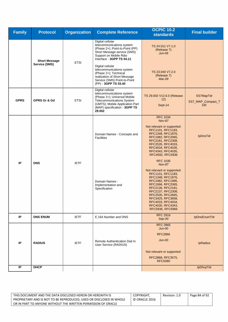
THIS DOCUMENT AND THE DATA DISCLOSED HEREIN OR HEREWITH IS PROPRIETARY AND IS NOT TO BE REPRODUCED, USED OR DISCLOSED IN WHOLE OR IN PART TO ANYONE WITHOUT THE WRITTEN PERMISSION OF ORACLE
COPYRIGHT, © ORACLE 2016
Revision: 1.0 Page 84 of 92
Family Protocol Organization Complete Reference OCPIC 10.2 standards
Final builder
Short Message Service (SMS)
ETSI
Digital cellular telecommunications system (Phase 2+); Point-to-Point (PP) Short Message service (SMS) Support on Mobile Rdio Interface - 3GPP TS 04.11 Digital cellular telecommunications system (Phase 2+); Technical realization of Short Message Service (SMS) Point-to-Point (PP) - 3GPP TS 03.40
TS 24.011 V7.1.0 (Release 7)
Jun-09
TS 23.040 V7.2.0 (Release 7)
Mar-09
GPRS GPRS Gr & Gd ETSI
Digital cellular telecommunications system (Phase 2+); Universal Mobile Telecommunications System (UMTS); Mobile Application Part (MAP) specification - 3GPP TS 29.002
TS 29.002 V12.6.0 (Release 12)
Sept-14
SS7MapTdr
SS7_MAP_Compact_TDR
IP DNS IETF
Domain Names - Concepts and Facilities
RFC 1034 Nov-87
Not relevant or supported: RFC1101, RFC1183, RFC1348, RFC1876, RFC1982, RFC2065, RFC2181, RFC2308, RFC2535, RFC4033, RFC4034, RFC4035, RFC4343, RFC4035, RFC4592, RFC5936
IpDnsTdr
Domain Names - Implementation and Specification
RFC 1035 Nov-87
Not relevant or supported: RFC1101, RFC1183, RFC1348, RFC1876, RFC1982, RFC1995, RFC1996, RFC2065, RFC2136, RFC2181, RFC2137, RFC2308, RFC2535, RFC2845, RFC3425, RFC3658, RFC4033, RFC4034, RFC4035, RFC4343, RFC5936, RFC5966
IP DNS ENUM IETF E.164 Number and DNS RFC 2916
Sep-00 IpDnsEnumTdr
IP RADIUS IETF Remote Authentication Dial In User Service (RADIUS)
RFC 2865 Jun-00
RFC2866
Jun-00
Not relevant or supported:
RFC2868, RFC3575, RFC5080
IpRadius
IP DHCP IpDhcpTdr

THIS DOCUMENT AND THE DATA DISCLOSED HEREIN OR HEREWITH IS PROPRIETARY AND IS NOT TO BE REPRODUCED, USED OR DISCLOSED IN WHOLE OR IN PART TO ANYONE WITHOUT THE WRITTEN PERMISSION OF ORACLE
COPYRIGHT, © ORACLE 2016
Revision: 1.0 Page 85 of 92
Family Protocol Organization Complete Reference OCPIC 10.2 standards
Final builder
BOOTP IETF Bootstrap protocol (BOOTP)
RFC 951 Sep-85
Not relevant or supported: RFC1395, RFC1497, RFC1532, RFC1542,
RFC5494
DHCP IETF Dynamic Host Configuration Protocol
RFC 2131 May-97
Not relevant or supported: RFC3396, RFC4361,
RFC5494
IP
WAP
IpWapv1Tdr
WTP WAP Forum /
OMA Wireless Transaction protocol
WAP-224-WTP-20010710-a Jul-01
WSP WAP Forum /
OMA WAP - Wireless Session Protocol Specification
WAP-230-WSP-20010705-p Jul-01
IP MMS OMA Multimedia Messaging Service Encapsulation Protocol Version 1.1
OMA-MMS-ENC-v1_1-20021030-C
Oct-02
IpMmsWapv1Tdr IpMmsWapv2Tdr
IP HTTP IETF Hypertext Transfer Protocol - HTTP/1.1
RFC 2616 Jun-99
Not relevant or supported: RFC2817, RFC5785,
RFC6266
IpHttpTdr
IP
WAP2 IETF Hypertext Transfer Protocol - HTTP/1.1
RFC 2616 Jun-99
Not relevant or supported: RFC2817, RFC5785,
RFC6266
IpWapv2Tdr
WAP Forum /
OMA WAP Architecture
WAP-210-WAPArch-20010712
Jul-01
IP POP3 IETF Post Office protocol - Version 3 RFC 1460
Jun-93 IpPop3Tdr
IP SMTP IETF Simple Mail Transfer Protocol RFC 2821
Apr-01 IpSmtpTdr
IP IMAP4 IETF Internet Message Access Protocol - Version 4rev1
RFC 2060 Mar-03
IpImap4Tdr
IP FTP IETF File Transfer Protocol
RFC 959 Oct-85
Not relevant or supported: RFC2228, RFC2640, RFC2773, RFC3659,
RFC5797
IpFtpTdr
IP TCP IETF Transmission Control Protocol
RFC 793 Sep-81
Not relevant or supported: RFC1122, RFC3168,
RFC6093
IpTcpCdr
IP RTSP IETF Real Time Streaming Protocol (RTSP)
RFC 2326 Apr-98
IpRtspTdr
IETF SDP:Session Description Protocol
RFC 2327 Apr-98
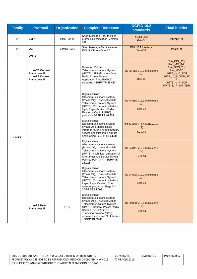
THIS DOCUMENT AND THE DATA DISCLOSED HEREIN OR HEREWITH IS PROPRIETARY AND IS NOT TO BE REPRODUCED, USED OR DISCLOSED IN WHOLE OR IN PART TO ANYONE WITHOUT THE WRITTEN PERMISSION OF ORACLE
COPYRIGHT, © ORACLE 2016
Revision: 1.0 Page 86 of 92
Family Protocol Organization Complete Reference OCPIC 10.2 standards
Final builder
IP SMPP SMS Forum Short Message Peer-to-Peer protocol Specification, Version 5.0
SMPP v5.0 Feb-03
IpSmppTdr
IP UCP Logica CMG Short Message Service center; EMI - UCP Interface 4.6
EMI UCP Interface May-05
IpUcpTdr
UMTS
UMTS
Iu-CS Control Plane over IP Iu-PS Control Plane over IP
Universal Mobile Telecommunications System (UMTS); UTRAN Iu interface Radio Access Network Application Part (RANAP) signalling - 3GPP TS 25.413
TS 25.413 V12.3.0 (Release 12)
Dec-14
Ran_CC2_Cdr Ran_MM_Tdr Ran_SMS_Tdr
Ran_USSD UMTS_Iu_C_TDR
UMTS_Iu_P_GMM_TDR
UMTS_Iu_P_TDR UMTS_Iu_P_SM_TDR
Digital cellular telecommunications system (Phase 2+); Universal Mobile Telecommunications System (UMTS); Mobile radio interface layer 3 specification; Radio Resource Control (RRC) protocol - 3GPP TS 44.018
TS 44.018 V12.3.0 (Release 12)
Sept-14
Digital cellular telecommunications system (Phase 2+); Mobile Radio interface layer 3 supplementary service specification; Formats and Coding - 3GPP TS 04.80
TS 24.080 V12.0.0 (Release 12)
Sept-14
Digital cellular telecommunications system (Phase 2+); Universal Mobile Telecommunications System (UMTS); Technical realization of Short Message Service (SMS) Point-to-Point (PP) - 3GPP TS 24.011
TS 24.011 V12.0.0 (Release 12)
Sept-14
Digital cellular telecommunications system (Phase 2+); Universal Mobile Telecommunications System (UMTS); Mobile radio interface Layer 3 specification; Core network protocols; Stage 3 - 3GPP TS 24.008
TS 24.008 V12.7.0 (Release 12)
Sept-14
Iu-PS User Plane over IP
ETSI
Digital cellular telecommunications system (Phase 2+); Universal Mobile Telecommunications System (UMTS); General Packet Radio Service (GPRS);GPRS Tunneling Protocol (GTP) accross the Gn and Gp Interface - 3GPP TS 09.60
TS 29.060 V12.6.0 (Release 12)
Sept-14

THIS DOCUMENT AND THE DATA DISCLOSED HEREIN OR HEREWITH IS PROPRIETARY AND IS NOT TO BE REPRODUCED, USED OR DISCLOSED IN WHOLE OR IN PART TO ANYONE WITHOUT THE WRITTEN PERMISSION OF ORACLE
COPYRIGHT, © ORACLE 2016
Revision: 1.0 Page 87 of 92
Family Protocol Organization Complete Reference OCPIC 10.2 standards
Final builder
VoIP
VoIP SIP / SIP-T / SIP-I
IETF SIP Session Initiation Protocol
RFC 3261 Jun-02
Not relevant or supported: RFC3853, RFC4320, RFC4916, RFC5393, RFC5621, RFC5626, RFC5630, RFC5922, RFC5954, RFC6026,
RFC6141
VoipSipCdr VoipSiptAnsiCdr VoipSiptItuCdr
IETF Reliability of Provisional Responses in the Session Initiation Protocol (SIP)
RFC 3262 Jun-02
IETF Session Initiation Protocol (SIP) - Specific Event Notification
RFC 3265 Jun-02
Not relevant or supported: RFC5367, RFC5727,
RFC6446
IETF The Session Initiation Protocol (SIP) UPDATE Method
RFC 3311 Sep-02
IETF The Session Initiation Protocol (SIP) Refer Method
RFC 3515 Apr-03
IETF The SIP INFO Method RFC 2976
Oct-00
IETF Session Initiation Protocol for Telephones (SIP-T): Context and Architectures
RFC 3372 Sep-02
IETF SDP:Session Description Protocol
RFC 2327 Apr-98
IETF Session Description Protocol (SDP) Simple Capability Declaration
RFC 3407
ITU-T
Interworking between Session Initiation Protocol (SIP) and Bearer Independant Call Control Protocol or ISDN User Part.
Q.1912-5 Mar-04
Nortel
CS2000 SIP/SIP-T
Interoperability Specification (Issue 0.82) System Requirement Document
Multiple Dialog Usages in the Session Initiation Protocol
Nortel CS2000 01/10/2003
RFC5057
VoIP
VoIP H.225/Q.931 ITU-T
Serie H: Audiovisual and Multimedia Systems - Call Signalling protocols and media stream packetisation for packet-based multimedia communication systems
H.225.0 Jul-03
VoipQ931Cdr
ITU-T ISDN user-network interface layer 3 specification for basic call control
Q.931 Dec-99
VoIP VoIP H.225/RAS ITU-T
Call Signalling protocols and media stream packetisation for packet-based multimedia communication systems
H.225.1 Jul-03
VoipRasTdr
VoIP VoIP H.245 ITU-T Control Protocol for multimrdia communication
H.245 Jul-03
VoipH245Tdr

THIS DOCUMENT AND THE DATA DISCLOSED HEREIN OR HEREWITH IS PROPRIETARY AND IS NOT TO BE REPRODUCED, USED OR DISCLOSED IN WHOLE OR IN PART TO ANYONE WITHOUT THE WRITTEN PERMISSION OF ORACLE
COPYRIGHT, © ORACLE 2016
Revision: 1.0 Page 88 of 92
Family Protocol Organization Complete Reference OCPIC 10.2 standards
Final builder
VoIP VoIP RTCP IETF RTP: A Transport Protocol for Real-Time Application
RFC 3550,
Jul-03
RFC3551
Jul-03
Not relevant or supported: RFC5506, RFC5761, RFC6051, RFC6222
VoipRtcpStats
VoIP
MGCP IETF Media Gateway Control Protocol (MGCP) version 1.0
RFC 3435 Jan-03
Not relevant or supported: RFC3661
VoipMgcpCdr VoipMgcpTdr
IETF
Media Gateway Control Protocol (MGCP) Return Code Usage
RFC 3661 Dec-03
IETF Media Gateway Control Protocol (MGCP) Packages
RFC 3660 Dec-03
VoIP MEGACO IETF Gateway Control Protocol Version 1.0
RFC 3525 Jun-03
VoipMEGACOTdr
VoIP H.248 ITU-T Gateway Control Protocol: Version 2
H.248.1 May-02
Supported packages H.248.2 until H.248.31
VoipH248Tdr
IMS Diameter IETF Diameter Base Protocol RFC 3588
Sep-03
ImsDiameterCcTdr ImsDiameterCxTdr ImsDiameterGqTdr ImsDiameterShTdr
ImsDiameterTdr
LTE_Diameter-TDR
Diameter Credit-Control (Cc, Ro, Rf, Gy, Ga)
IETF Diameter Credit-Control Application
RFC 4006 Aug-05
ETSI / 3GPP
3rd Generation Partnership Project; Technical Specification Group Service and System Aspects; Telecommunication management; Charging management;
Diameter charging applications
TS 32.299 V12.6.0 (Release 12)
Sept-14
Diameter Gq ETSI
Universal Mobile Telecommunications System (UMTS); Policy control over Gq interface (3GPP TS 29.209 version 6.5.0 Release 6) . Replaced by Rx in LTE
TS 29.209 V6.5.0 (Release 6)
Jun-06
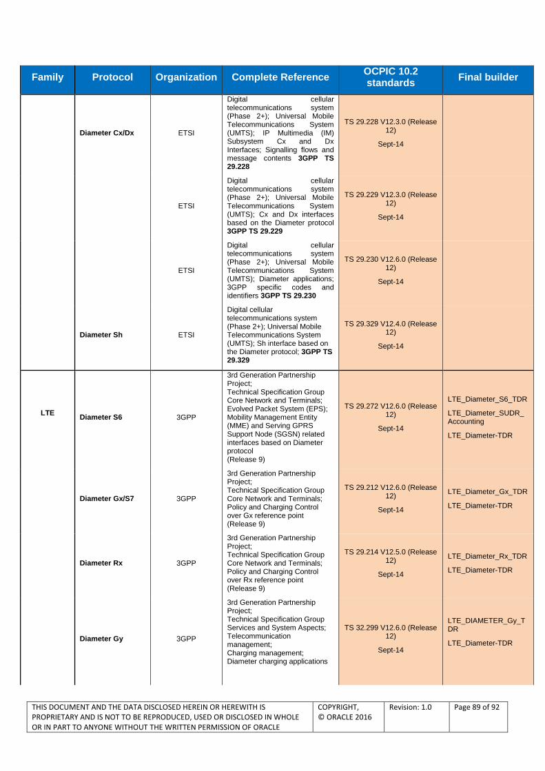
THIS DOCUMENT AND THE DATA DISCLOSED HEREIN OR HEREWITH IS PROPRIETARY AND IS NOT TO BE REPRODUCED, USED OR DISCLOSED IN WHOLE OR IN PART TO ANYONE WITHOUT THE WRITTEN PERMISSION OF ORACLE
COPYRIGHT, © ORACLE 2016
Revision: 1.0 Page 89 of 92
Family Protocol Organization Complete Reference OCPIC 10.2 standards
Final builder
Diameter Cx/Dx ETSI
Digital cellular telecommunications system (Phase 2+); Universal Mobile Telecommunications System (UMTS); IP Multimedia (IM) Subsystem Cx and Dx Interfaces; Signalling flows and message contents 3GPP TS 29.228
TS 29.228 V12.3.0 (Release 12)
Sept-14
ETSI
Digital cellular telecommunications system (Phase 2+); Universal Mobile Telecommunications System (UMTS); Cx and Dx interfaces based on the Diameter protocol 3GPP TS 29.229
TS 29.229 V12.3.0 (Release 12)
Sept-14
ETSI
Digital cellular telecommunications system (Phase 2+); Universal Mobile Telecommunications System (UMTS); Diameter applications; 3GPP specific codes and identifiers 3GPP TS 29.230
TS 29.230 V12.6.0 (Release 12)
Sept-14
Diameter Sh ETSI
Digital cellular telecommunications system (Phase 2+); Universal Mobile Telecommunications System (UMTS); Sh interface based on the Diameter protocol; 3GPP TS 29.329
TS 29.329 V12.4.0 (Release 12)
Sept-14
LTE
Diameter S6 3GPP
3rd Generation Partnership Project; Technical Specification Group Core Network and Terminals; Evolved Packet System (EPS); Mobility Management Entity (MME) and Serving GPRS Support Node (SGSN) related interfaces based on Diameter protocol (Release 9)
TS 29.272 V12.6.0 (Release 12)
Sept-14
LTE_Diameter_S6_TDR
LTE_Diameter_SUDR_Accounting
LTE_Diameter-TDR
Diameter Gx/S7 3GPP
3rd Generation Partnership Project; Technical Specification Group Core Network and Terminals; Policy and Charging Control over Gx reference point (Release 9)
TS 29.212 V12.6.0 (Release 12)
Sept-14
LTE_Diameter_Gx_TDR
LTE_Diameter-TDR
Diameter Rx 3GPP
3rd Generation Partnership Project; Technical Specification Group Core Network and Terminals; Policy and Charging Control over Rx reference point (Release 9)
TS 29.214 V12.5.0 (Release 12)
Sept-14
LTE_Diameter_Rx_TDR
LTE_Diameter-TDR
Diameter Gy 3GPP
3rd Generation Partnership Project; Technical Specification Group Services and System Aspects; Telecommunication management; Charging management; Diameter charging applications
TS 32.299 V12.6.0 (Release 12)
Sept-14
LTE_DIAMETER_Gy_TDR
LTE_Diameter-TDR

THIS DOCUMENT AND THE DATA DISCLOSED HEREIN OR HEREWITH IS PROPRIETARY AND IS NOT TO BE REPRODUCED, USED OR DISCLOSED IN WHOLE OR IN PART TO ANYONE WITHOUT THE WRITTEN PERMISSION OF ORACLE
COPYRIGHT, © ORACLE 2016
Revision: 1.0 Page 90 of 92
Family Protocol Organization Complete Reference OCPIC 10.2 standards
Final builder
Diameter S9 3GPP
3rd Generation Partnership Project; Technical Specification Group Core Network and Terminals; Policy and Charging Control (PCC) over S9 reference point; Stage 3
TS 29.215 V12.5.0 (Release 12)
Sept-14
LTE_DIAMETER_S9_TDR
LTE_Diameter-TDR
Diameter AAA 3GPP
3rd Generation Partnership Project;
Technical Specification Group Core Network and Terminals;
Evolved Packet System (EPS);
3GPP EPS AAA interfaces
TS 29.273 V12.5.0 (Release 12)
Sept-14
LTE_Diameter_AAA_TDR
Diameter LCS 3GPP 3rd Generation Partnership Project;
Technical Specification Group Core Network and Terminals;
Location Services (LCS); Evolved Packet Core (EPC) LCS Protocol (ELP) between the Gateway Mobile Location Centre (GMLC) and the Mobile Management Entity (MME); SLg interface
3rd Generation Partnership
Project;
Technical Specification Group
Core Network and Terminals;
Location Services (LCS);
Diameter-based SLh interface
for Control Plane LCS
TS 29.172 V12.4.0 (Release 12)
Mar-14
TS 29.173 V12.2.0 (Release 12)
Sept-14
LTE_Diameter_LCS_TDR
GTPv2 3GPP
3rd Generation Partnership Project; Technical Specification Group Core Network and Terminals; 3GPP Evolved Packet System (EPS); Evolved General Packet Radio Service (GPRS) Tunnelling Protocol for Control plane (GTPv2-C); Stage 3 (Release 9)
TS 29.274 V12.6.0 (Release 12)
Sept-14
LTE_GTP_v2_Tunnel_Management_TDR
LTE_GTP_v2_Mobility_Management_TDR
LTE_GTP_v2_Sv_TDR
S1-AP 3GPP
3rd Generation Partnership Project; Technical Specification Group Radio Access Network; Evolved Universal Terrestrial Radio Access Network (E-UTRAN); S1 Application Protocol (S1AP) (Release 9)
TS 36.413 V12.3.0 (Release 12)
Sept-14
LTE_S1AP_TDR
RAN_ESM_TDR
RAN_EMM_TDR
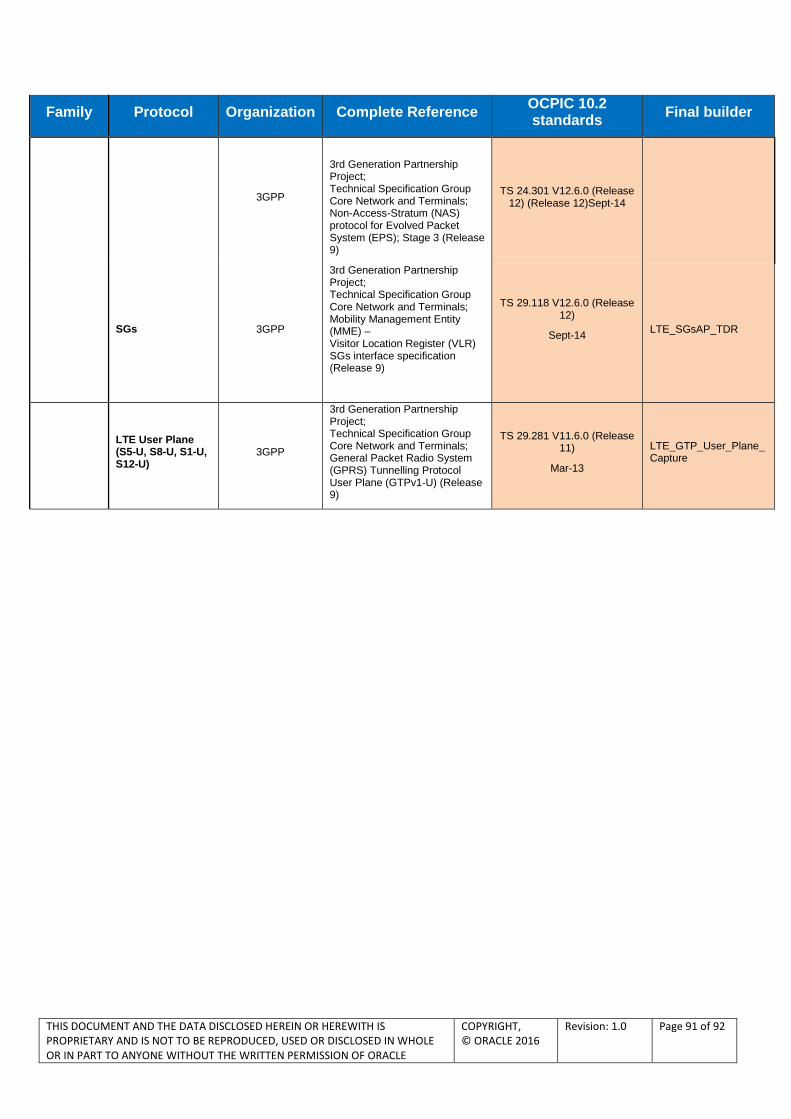
THIS DOCUMENT AND THE DATA DISCLOSED HEREIN OR HEREWITH IS PROPRIETARY AND IS NOT TO BE REPRODUCED, USED OR DISCLOSED IN WHOLE OR IN PART TO ANYONE WITHOUT THE WRITTEN PERMISSION OF ORACLE
COPYRIGHT, © ORACLE 2016
Revision: 1.0 Page 91 of 92
Family Protocol Organization Complete Reference OCPIC 10.2 standards
Final builder
3GPP
3rd Generation Partnership Project; Technical Specification Group Core Network and Terminals; Non-Access-Stratum (NAS) protocol for Evolved Packet System (EPS); Stage 3 (Release 9)
TS 24.301 V12.6.0 (Release 12) (Release 12)Sept-14
SGs 3GPP
3rd Generation Partnership Project; Technical Specification Group Core Network and Terminals; Mobility Management Entity (MME) – Visitor Location Register (VLR) SGs interface specification (Release 9)
TS 29.118 V12.6.0 (Release 12)
Sept-14
LTE_SGsAP_TDR
LTE User Plane (S5-U, S8-U, S1-U, S12-U)
3GPP
3rd Generation Partnership Project; Technical Specification Group Core Network and Terminals; General Packet Radio System (GPRS) Tunnelling Protocol User Plane (GTPv1-U) (Release 9)
TS 29.281 V11.6.0 (Release 11)
Mar-13
LTE_GTP_User_Plane_Capture

THIS DOCUMENT AND THE DATA DISCLOSED HEREIN OR HEREWITH IS PROPRIETARY AND IS NOT TO BE REPRODUCED, USED OR DISCLOSED IN WHOLE OR IN PART TO ANYONE WITHOUT THE WRITTEN PERMISSION OF ORACLE
COPYRIGHT, © ORACLE 2016
Revision: 1.0 Page 92 of 92
Oracle Corporation
World Headquarters
500 Oracle Parkway
Redwood Shores, CA 94065
U.S.A.
Worldwide Inquiries:
Phone: +1.650.506.7000
Fax: +1.650.506.7200
oracle.com
Copyright © 2016, Oracle and/or its affiliates. All rights reserved.
This document is provided for information purposes only, and the contents hereof are subject to change without notice. This
document is not warranted to be error-free, nor subject to any other warranties or conditions, whether expressed orally or implied in
law, including implied warranties and conditions of merchantability or fitness for a particular purpose. We specifically disclaim any
liability with respect to this document, and no contractual obligations are formed either directly or indirectly by this document. This
document may not be reproduced or transmitted in any form or by any means, electronic or mechanical, for any purpose, without our
prior written permission.
Oracle and Java are registered trademarks of Oracle and/or its affiliates. Other names may be trademarks of their respective owners.
Intel and Intel Xeon are trademarks or registered trademarks of Intel Corporation. All SPARC trademarks are used under license and
are trademarks or registered trademarks of SPARC International, Inc. AMD, Opteron, the AMD logo, and the AMD Opteron logo are
trademarks or registered trademarks of Advanced Micro Devices. UNIX is a registered trademark of The Open Group. 0113


