30


ORAL AND MAXILLOFACIAL RADIOLOGYA DIAGNOSTIC APPROACH


ORAL AND MAXILLOFACIAL RADIOLOGYA DIAGNOSTIC APPROACH
David MacDonald, BDS, BSc(Hons.), LLB(Hons.), MSc, DDS(Edin.), DDRRCR, FDSRCPS, FRCD(C)
A John Wiley & Sons, Inc., Publication

This edition fi rst published 2011
© 2011 David MacDonald
Blackwell Publishing was acquired by John Wiley & Sons in February 2007. Blackwell’s publishing program has been merged with Wiley’s global Scientifi c, Technical and Medical business to form Wiley-Blackwell.
Registered offi ce: John Wiley & Sons Ltd, The Atrium, Southern Gate, Chichester, West Sussex, PO19 8SQ, UK
Editorial offi ces: 2121 State Avenue, Ames, Iowa 50014–8300, USA
The Atrium, Southern Gate, Chichester, West Sussex, PO19 8SQ, UK
9600 Garsington Road, Oxford, OX4 2DQ, UK
For details of our global editorial offi ces, for customer services and for information about how to apply for permission to reuse the copyright material in this book please see our website at www.wiley.com/wiley-blackwell.
Authorization to photocopy items for internal or personal use, or the internal or personal use of specifi c clients, is granted by Blackwell Publishing, provided that the base fee is paid directly to the Copyright Clearance Center, 222 Rosewood Drive, Danvers, MA 01923. For those organizations that have been granted a photocopy license by CCC, a separate system of payments has been arranged. The fee codes for users of the Transactional Reporting Service are ISBN-13: 978–0-8138–1414–8/2011.
Designations used by companies to distinguish their products are often claimed as trademarks. All brand names and product names used in this book are trade names, service marks, trademarks or registered trademarks of their respective owners. The publisher is not associated with any product or vendor mentioned in this book. This publication is designed to provide accurate and authoritative information in regard to the subject matter covered. It is sold on the understanding that the publisher is not engaged in rendering professional services. If professional advice or other expert assistance is required, the services of a competent professional should be sought.
DisclaimerThe contents of this work are intended to further general scientifi c research, understanding, and discussion only and are not intended and should not be relied upon as recommending or promoting a specifi c method, diagnosis, or treatment by practitioners for any particular patient. The publisher and the author make no representations or warranties with respect to the accuracy or completeness of the contents of this work and specifi cally disclaim all warranties, including without limitation any implied warranties of fi tness for a particular purpose. In view of ongoing research, equipment modifi cations, changes in governmental regulations, and the constant fl ow of information relating to the use of medicines, equipment, and devices, the reader is urged to review and evaluate the information provided in the package insert or instructions for each medicine, equipment, or device for, among other things, any changes in the instructions or indication of usage and for added warnings and precautions. Readers should consult with a specialist where appropriate. The fact that an organization or Website is referred to in this work as a citation and/or a potential source of further information does not mean that the author or the publisher endorses the information the organization or Website may provide or recommendations it may make. Further, readers should be aware that Internet Websites listed in this work may have changed or disappeared between when this work was written and when it is read. No warranty may be created or extended by any promotional statements for this work. Neither the publisher nor the author shall be liable for any damages arising herefrom.
Front cover photo credits:Top image: Courtesy of Dr. Montgomery MartinSecond image from top: Courtesy of Dr. Babak ChehroudiBottom image: Courtesy of Dr. Montgomery Martin
Library of Congress Cataloging-in-Publication Data
MacDonald, David, 1955- Oral and maxillofacial radiology : a diagnostic approach / David MacDonald. p. ; cm. Includes bibliographical references and index. ISBN 978-0-8138-1414-8 (hardcover : alk. paper) 1. Mouth–Radiography. 2. Maxilla–Radiography. 3. Face–Radiography. I. Title. [DNLM: 1. Diagnostic Imaging. 2. Stomatognathic System–pathology. 3. Diagnosis, Oral. WN 230] RK309.M33 2011 617.5'22075–dc22 2010041339
A catalogue record for this book is available from the British Library.
This book is published in the following electronic formats: ePDF 9780470958797; ePub 9780470958803
Set in 10.5 on 12 pt ITC Slimbach by Toppan Best-set Premedia Limited
1 2011

To my mother, my daughter, Amy, and to my wife


Contents
Author and contributors ix
Preface xi
Part 1 Introduction 3
Chapter 1 Basics of radiological diagnosis 5D. MacDonald
Chapter 2 Viewing conditions 37D. MacDonald
Chapter 3 Physiological phenomena and radiological interpretation 44D. MacDonald
Part 2 Advanced imaging modalities 47
Chapter 4 Helical computed tomography 49D. MacDonald
Chapter 5 Cone-beam computed tomography 59D. MacDonald
Chapter 6 Magnetic resonance imaging 67D. MacDonald
Chapter 7 Positron emission tomography 84D. MacDonald
Chapter 8 Basics of ultrasound 88D. MacDonald
Part 3 Radiological pathology of the jaws 91
Chapter 9 Radiolucencies 93D. MacDonald
Chapter 10 Radiopacities 151D. MacDonald
Chapter 11 Maxillary antrum 195D. MacDonald
Chapter 12 Temporomandibular joint 225D. MacDonald
Chapter 13 Imaging of the salivary glands 233D. MacDonald
vii
viii Contents
Chapter 14 Fractures of the face and jaws 244D. MacDonald
Chapter 15 Osseointegrated implants 249T. Li and D. MacDonald
Part 4 Radiological pathology of the extragnathic head and neck regions 267
Chapter 16 Introduction 269D. MacDonald and M. Martin
Chapter 17 Benign lesions 278M. Martin and D. MacDonald
Chapter 18 Malignant lesions 304M. Martin and D. MacDonald
Index 341

Author and Contributors
Author
Dr. David MacDonald, BDS, BSc(Hons.), LLB(Hons.), MSc, DDS(Edin.), DDRRCR, FDSRCPS, FRCD(C) Associate Professor and Chairman, Division of Oral and Maxillofacial Radiology Faculty of Dentistry The University of British Columbia Vancouver, BC, Canada
With contributions by
Dr. Montgomery Martin, MD, FRCP(C) Clinical Director, Department of Diagnostic Imaging British Columbia Cancer Agency Faculty of Radiology The University of British Columbia Vancouver, BC, Canada
Dr. Thomas Li, BDS, MSc, DDRRCR, DGDP(UK), FCDSHK, FHKAM Former Head, Oral and Maxillofacial Radiology Faculty of Dentistry The University of Hong Kong Currently in full - time Oral and Maxillofacial Radiology specialist practice
ix

Preface
The purpose of this textbook is to guide diagnosti-cians of all skill levels in generating a diagnosis for lesions affecting the face and jaws. Although its primary readership will be oral and maxillofacial and head and neck specialists, much of it is rele-vant to the general and specialist dentist and senior dental student, who, in service of the community at large, are most likely to encounter these lesions fi rst. Therefore, the fi gures are appropriately detailed to facilitate comprehension and correla-tion with current standard textbooks with which the dentist is likely to be familiar.
This book focuses on new and/or important lesions and their appropriate imaging needs. These imaging needs include the modalities of helical and cone - beam computed tomography, magnetic reso-nance imaging, and positron emission tomogra-phy. Ultrasonography is introduced.
Over the last decade, imaging in dentistry has been substantially transformed by the advent of cone - beam computed tomography. The moderate - to - large fi elds of view of this modality display the base of the skull and the neck. Although these regions are the proper interpretative remit of the medical radiologist, the nonradiologist reader should be able to recognize any abnormality that may be displayed in these regions so that it can be appropriately referred for diagnosis by a radiolo-gist. This book bridges the gap between current textbooks in oral and maxillofacial radiology and those of head and neck (medical) radiology by including Chapters 16 , 17 , and 18 , cowritten with a medical radiologist and dedicated to the more common and important lesions likely to be imaged in the neck and base of the skull.
xi


ORAL AND MAXILLOFACIAL RADIOLOGYA DIAGNOSTIC APPROACH


Part 1
Introduction

5
Chapter 1
Basics of r adiological d iagnosis
Introduction
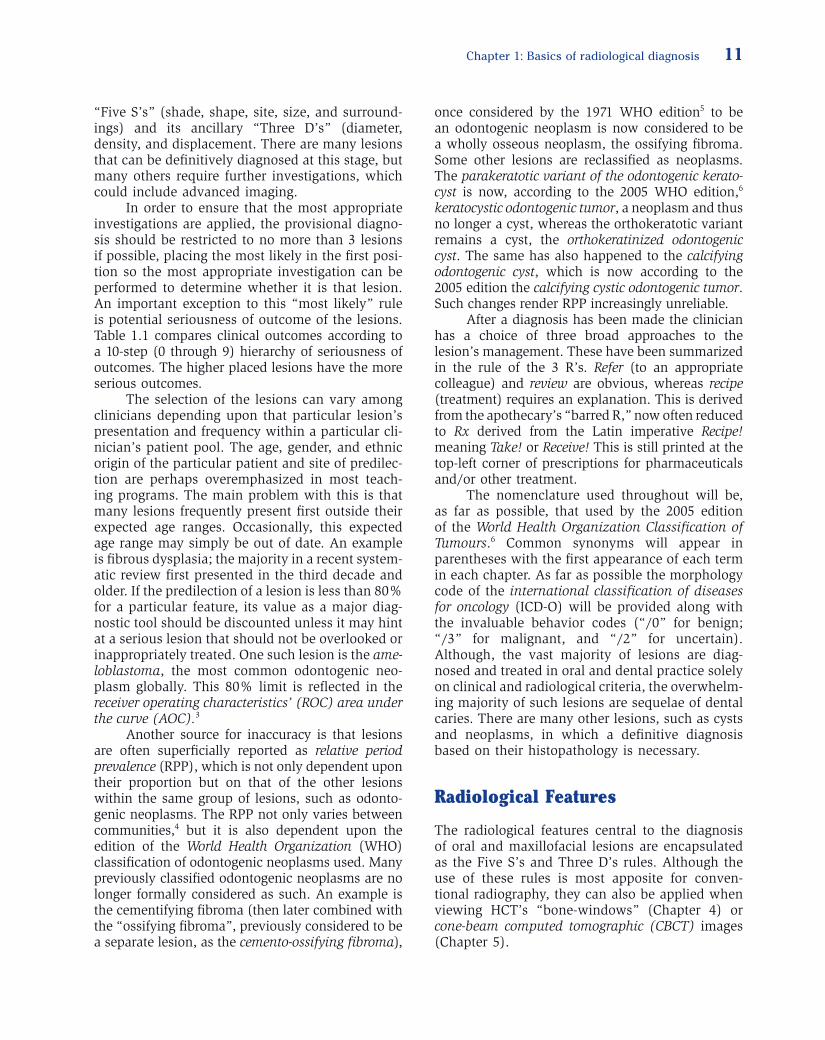
The clinician should understand how the image is made and the normal anatomy and its variants in order to be able to identify artifacts, particularly those that can mimic the appearance of disease. Although these elements, as they present on conven-tional radiography , are addressed in detail by the wide range of dental radiology texts currently avail-able, this textbook ’ s fi gure legends note features caused by incorrect panoramic technique, artifacts, and variations of normal radiographic anatomy. Figure 1.1 outlines the main attributes of the imaging modalities that are featured in this textbook. These imaging modalities have been broadly divided into conventional radiography and advanced imaging.
Diagnosis in oral and maxillofacial radiology is most frequently based both on the clinical fi nd-ings (including presenting complaint and history) and on the features observed on conventional radiographs. A defi nitive diagnosis is possible for a large proportion of lesion types that present to the primary care dentist. These lesions do not include just those lesions of infl ammatory origin that present as periapical radiolucencies (on histo-logical examination: granuloma , periapical cyst , or periapical abscess) and condensing osteitis , but also dentigerous cysts and dense bone island (also known as idiopathic osteosclerosis ). They are not only the most frequently occurring lesions affect-ing the jaws, but a majority of them also have distinctive clinical and radiological presentations. Some other lesions such as fl orid osseous dyspla-sia , the cementoblastoma , the compound odon-toma , and some cases of odontogenic myxoma can be defi nitively diagnosed solely on their radiologi-cal appearance. In those situations where a defi ni-tive diagnosis is not possible, a differential diagnosis should be developed. This will consist of two or
more lesions. Such cases are frequently referred to a specialist as much for a diagnosis as for treat-ment. In order to assist the reader in his/her diag-nosis this textbook is illustrated throughout with diagnostic fl owcharts.
There is an expectation that the images created should adequately display the area of clini-cal interest with the purpose of addressing those clinical questions that indicated the need for the investigations. Thus the image or images should display the entire area of pathology and be free of artifacts. Therefore, an unerupted third molar should not only include the entire tooth and its follicle, but also at least a clear margin of 1 mm around them. This would allow the clinician to determine whether it is close to the mandibular canal or any other adjacent structure.
An example of inadequacy of the radiography resulted in a Canadian dental malpractice case that continued for 12 years through at least fi ve courts before it was concluded, presumably settled. 1 The only positive result of this failure to include only 98% of a third molar was its not insignifi cant con-tribution to Canadian law specifi cally and common law in general. From reading the case it is abun-dantly clear that if an adequate radiograph or radiographs had been taken in the fi rst instance this case would have had little grounds upon which to proceed, and the spilling of so much legal ink and personal and professional distress would have been avoided.
Radiographs are prescribed for three reasons, diagnosis, presurgical planning and follow - up. Those prescribed for the purpose of diagnosis and/or presurgical planning should be made prior to biopsy because this can change the radiology of the lesion appreciably. This is particularly so with regard to advanced imaging such as helical com-puted tomography (HCT) and magnetic resonance imaging (MRI). Two cases demonstrate the effects of biopsy prior to HCT.
The biopsy of an odontogenic myxoma, a locally invasive benign neoplasm, prior to HCT,
Oral and Maxillofacial Radiology: A Diagnostic Approach, David MacDonald. © 2011 David MacDonald

Figure 1.1. The modalities used in oral and maxillofacial radiology. This is an overview of the main imaging modalities, including remarks concerning their clearest clinical uses, relative advantages over other modalities, and limitations of use.
Modalities used in oral and maxillofacial radiology
Intraoral radiographyRemarks
1. Best spatial resolution
Conventional Radiography Advanced Imaging
Advantages: 1. primary diagnosis of lesions affecting: Maxillary antrum (Chapter 11) Facial fractures (Chapter 14) Lesions of the base of the skull and the soft tissues of the head and neck (Chapter 16–18) 2. Refines differential diagnosis acquired by conventional radiography of the jaws 3. Optimizes treatment planning Displays full extent of lesion Permits more accurate measurementDisadvantage: Poor spatial resolution
Advantage: Majority of jaw lesions (Chapters 9 & 10) are diagnosed radiologically because of Superior spatial resolution Cost—low Access—easy & widely availableDisadvantage: 2-dimensional image of a 3-dimensional structure—superimposition
Cross-sectional and3-dimensional imaging
Ionizing radiation
X-ray generatorComputed tomography
UltrasonographyChapter 8
Panoramic radiographyRemarks
1. Moderate spatial resolution2. Overview of jaws3. Distortion in horizontal plane
Annihilation radiationPositronemission
tomography(PET)
Chapter 7Remarks
1. Detection of unknown primary2. Distant metastasis
Helical CT(HCT)Chapter 4Remarks
1. Bone, soft-tissue and air windows2. Can use supine with i.v. contrast
CBCTChapter 5Remarks
1. Bone window only2. Better spatial resolution than HCT
GrayscaleRemarks
1. Measurements2. Salivary glands Chapter 13 & 173. 3-dimensional currently only in obstetrics
DopplerRemarks
1. Vascularity2. Blood flow
Magneticresonance
imaging (MRI)Chapter 6Remarks
1. T2 best for pathology2. Bone and air are ‘black’3. Fat is also ‘black’ if fat saturated4. Can use i.v. contrast5. Modality of choice for temporomandibular dysfunction Chapter 12
Fan-beam Cone-beam
6

Chapter 1: Basics of radiological diagnosis 7
provoked an infl ammatory response within the depth of the lesion, which was enhanced by the intravenous contrast (Figure 1.2 ). Contrast is rec-ommended for lesions, which include a neoplasm or a vascular lesion in their differential diagnosis. This, with regard to neoplasms, is important to determine local invasion of adjacent soft tissues, which would need to be resected along with the rest of the neoplasm.
Figure 1.3 displays a case of fi brous dyspla-sia , which caused a substantial expansion of the affected mandible. When it was fi rst seen by gen-eral surgeons unfamiliar with its manifestation in
Figure 1.2. A computed tomograph of an odontogenic myxoma carried out after the lesion had been biopsied. The biopsy site still has its dressing in place (Figure 1.2a and 1.2b). As a result there was enhancement (Figure 1.2c) by the intrave-nous contrast at the site biopsied that is more likely to refl ect hyperemia in response to the trauma of surgery. Note: All the major blood vessels including the facial and lingual arteries are enhanced in Figure 1.2c. Figure 1.2c reprinted with permission from MacDonald - Jankowski DS, Yeung R, Li TK, Lee KM. Computed tomography of odontogenic myxoma. Clinical Radiology 2004;59:281 – 287.
(a)
(b)
(c)
the jaws they performed multiple biopsies. These biopsies created their own artifacts on a subse-quent HCT. These artifacts were loss of cortex and dysplastic tissue exuding through a biopsy site.
Conventional radiography will be the fi rst imaging modality to be prescribed to investigate further a lesion occurring within the bony jaws obvious to or suspected by the clinical history and/or examination. For the majority of lesions affecting the jaws, conventional radiography is likely to be the sole imaging modality deemed clinically necessary. The principal advantages of conventional radiography are its superior spatial

8 Part 1. Introduction
should be carefully reviewed to identify any pathol-ogy that may be incidental to the patient ’ s com-plaint and the results of the clinical examination.
The panoramic radiograph in addition to per-mitting determination of the specifi c features of the lesion or suspected lesion that prompted its making, can also reveal macroscopic abnormalities such as size differences and changes in a specifi c anatomi-cal location (Figure 1.4 ) Furthermore, it can com-pliment the clinical examination by confi rming defects in the dental development, such as the number, eruption, size, and even structure of the teeth (Figure 1.5 ). Because these features have been fully addressed in other texts and are gener-ally well understood, space constraints preclude offering images of them here.
The various lesions, occurring within the face and jaws, often present with similar features at certain stages. Most will at some stage present as a radiolucency as they create space for further growth within the bony jaws. The borders of this radiolucency give a further clue as to their intrinsic behavior. Encapsulated benign neoplasms and many uninfected cysts grow at a moderate pace and are generally well defi ned. They may even have a cortex. Infected lesions and malignancies are generally associated by a poorly defi ned margin refl ecting their more aggressive infi ltrative expan-sion into previously normal bone. Sometimes, if the infected lesion becomes less virulent the adja-cent bone may respond by laying down more bone on the trabeculae resulting in sclerosis.
Slow - growing lesions, such as most cysts and encapsulated neoplasms, can displace teeth and adjacent structures such as the mandibular canal and cortices. More aggressive lesions are more likely to resorb them. Some malignancies, such as a squamous cell carcinoma , will destroy structures with very little displacement, whereas others will provoke a periosteal reaction such as the onion layer typical of osteogenic sarcoma or Ewing ’ s tumor. Such periosteal reaction can occur in chronic osteomyelitis . Such periosteal reactions are fre-quently seen in the extragnathic skeleton 2 but are infrequently seen in the jaws.
After the lesion has been properly imaged and reviewed the clinician reaches the point at which s/he wants to identify the lesion. Because the aim at this stage is to achieve, if possible, a defi nitive diagnosis it follows that this is best accomplished if the images of the lesion have been scrupulously reviewed. To this end I developed the rule of the
Figure 1.3. This is a bone - window axial computed tomog-raphy of fi brous dysplasia affecting the vertical ramus of the mandible. The cortical defects are the result of several biopsies performed prior to referral for computed tomogra-phy. Such operations can largely invalidate any clinically important radiological fi ndings because these, if errone-ous, could lead to a wrong diagnosis and inappropriate treatment. Note: Radiology is very central to the diagnosis of specifi c fi bro - osseous lesions , discussed later.
resolution (especially of the intraoral technologies), low radiation dose, and low cost. It is also available in the dental offi ce or surgery. It is most likely that this prescription will include a panoramic radio-graph that may be accompanied by intraoral radio-graphs. These images may be in either analogue (fi lm) or digital format. An overview of the various conventional radiographic technologies is set out in Table 2.1 . The panoramic radiograph permits an overview of the jaws from condyle to condyle. It also permits comparison between sides. These premises can be valid only if the patient is properly positioned within the panoramic radiographic unit exposed by the most appropriate exposure factors and the image is properly developed. Finally it is also expected that the resultant image is properly reviewed (read) under optimal viewing conditions (see Chapter 2 ). To reiterate, all prescriptions for a radiological investigation must be based upon a thorough clinical examination. Although there is little, if no, place for routine radiographic screening in the modern practice of dentistry, every image

Figure 1.4. Classifi cation of macroscopic abnormalities.
AchondroplasiaCleidocranial dysostosisCleft palate
Cleidocranial dysostosis
Racial/familialEdentulousAcromegaly
Seen on a lateralprojection
Bilateral Unilateral(asymmetry)
Increase in one side
Hemifacial hyperplasiaFibrous dysplasiaHemangiomaNeurofibroma
MalocclusionUnilateral AnkylosisHemifacial hypoplasia
MalocclusionCondylar hyperplasia
Hemifacial hypoplasiaTMJ ankylosis due to forceps delivery early radiotherapy
Decrease in one side To affected side From affected Side
Persistentsuture
Deviationof the chin
Increased size
Prognathism Retrognathism
Seen on ananterioposterior
projection
Mandible
Body —vertical height
Symphysis Gonial Angle
Obtuse AntegonialNotch
InfantEdentulous
Increased
RacialAcromegaly
AcromegalyPaget’s Disease
Edentulous
Decreased
Decreased size
EdentulousAno/Hypodontia
TMJ ankylosisJuvenileidiopathic arthritisTreacher-Collin
TMJ
Size Specific anatomical feature
Macroscopic Abnormalities
9

Figure 1.5. Classifi cation of developmental lesions of dental lamina origin.
HypopituitismHypoparathyroidismHypothyroidismVitamin D deficiency
Developmental lesions of dental lamina origin
Number
Ano/hypodontia Hyperdontia Delayed
Local
True
Metabolic Genetic Environmental
Change inMATRIX
Change in tooth germSHAPE
False
Hereditary hyperplasticgingivitis
Macroscopicallytoothlike
MacroscopicallyNOT toothlike
Odontoma
RootCrownHereditary
Hereditary
Acquired
Idiopathic Acquired Acquired
Macrodont MicrodontSimple
Systemic Systemic Systemic
Simple
Premature
Hyperthroidism
Relative True
Eruption Size Structure
Ectodermal dysplasiaDown’s syndrome
Cleidocranial dysostosisEpidermolysis bullosa
Amelogenesis imperfectaDentinogenesis imperfecta
Childhood illnessFluorosis
Congenital syphylisTurner’s tooth
Dentinogenesis imperfectaTaurodontism
DilacerationDens in dente
Radiotherapy
Down’s syndrome
Cleidocranial dysostosisGardner’s syndrome
Unilateral Unilateral
HemangiomaNeurofibroma
Gigantism Radiotherapy
Bilateral Bilateral
10
Chapter 1: Basics of radiological diagnosis 11
“ Five S ’ s ” (shade, shape, site, size, and surround-ings) and its ancillary “ Three D ’ s ” (diameter, density, and displacement. There are many lesions that can be defi nitively diagnosed at this stage, but many others require further investigations, which could include advanced imaging.
In order to ensure that the most appropriate investigations are applied, the provisional diagno-sis should be restricted to no more than 3 lesions if possible, placing the most likely in the fi rst posi-tion so the most appropriate investigation can be performed to determine whether it is that lesion. An important exception to this “ most likely ” rule is potential seriousness of outcome of the lesions. Table 1.1 compares clinical outcomes according to a 10 - step (0 through 9) hierarchy of seriousness of outcomes. The higher placed lesions have the more serious outcomes.
The selection of the lesions can vary among clinicians depending upon that particular lesion ’ s presentation and frequency within a particular cli-nician ’ s patient pool. The age, gender, and ethnic origin of the particular patient and site of predilec-tion are perhaps overemphasized in most teach-ing programs. The main problem with this is that many lesions frequently present fi rst outside their expected age ranges. Occasionally, this expected age range may simply be out of date. An example is fi brous dysplasia; the majority in a recent system-atic review fi rst presented in the third decade and older. If the predilection of a lesion is less than 80% for a particular feature, its value as a major diag-nostic tool should be discounted unless it may hint at a serious lesion that should not be overlooked or inappropriately treated. One such lesion is the ame-loblastoma , the most common odontogenic neo-plasm globally. This 80% limit is refl ected in the receiver operating characteristics ’ (ROC) area under the curve (AOC). 3
Another source for inaccuracy is that lesions are often superfi cially reported as relative period prevalence (RPP), which is not only dependent upon their proportion but on that of the other lesions within the same group of lesions, such as odonto-genic neoplasms. The RPP not only varies between communities, 4 but it is also dependent upon the edition of the World Health Organization (WHO) classifi cation of odontogenic neoplasms used. Many previously classifi ed odontogenic neoplasms are no longer formally considered as such. An example is the cementifying fi broma (then later combined with the “ ossifying fi broma ” , previously considered to be a separate lesion, as the cemento - ossifying fi broma ),
once considered by the 1971 WHO edition 5 to be an odontogenic neoplasm is now consid ered to be a wholly osseous neoplasm, the ossifying fi broma. Some other lesions are reclassifi ed as neoplasms. The parakeratotic variant of the odontogenic kerato-cyst is now, according to the 2005 WHO edition, 6 keratocystic odontogenic tumor , a neoplasm and thus no longer a cyst, whereas the orthokeratotic variant remains a cyst, the orthokeratinized odontogenic cyst . The same has also happened to the calcifying odontogenic cyst , which is now according to the 2005 edition the calcifying cystic odontogenic tumor . Such changes render RPP increasingly unreliable.
After a diagnosis has been made the clinician has a choice of three broad approaches to the lesion ’ s management. These have been summarized in the rule of the 3 R ’ s. Refer (to an appropriate colleague) and review are obvious, whereas recipe (treatment) requires an explanation. This is derived from the apothecary ’ s “ barred R, ” now often reduced to Rx derived from the Latin imperative Recipe! meaning Take! or Receive! This is still printed at the top - left corner of prescriptions for pharmaceuticals and/or other treatment.
The nomenclature used throughout will be, as far as possible, that used by the 2005 edition of the World Health Organization Classifi cation of Tumours . 6 Common synonyms will appear in parentheses with the fi rst appearance of each term in each chapter. As far as possible the morphology code of the international classifi cation of diseases for oncology (ICD - O) will be provided along with the invaluable behavior codes ( “ /0 ” for benign; “ /3 ” for malignant, and “ /2 ” for uncertain). Although, the vast majority of lesions are diag-nosed and treated in oral and dental practice solely on clinical and radiological criteria, the overwhelm-ing majority of such lesions are sequelae of dental caries. There are many other lesions, such as cysts and neoplasms, in which a defi nitive diagnosis based on their histopathology is necessary.
Radiological Features
The radiological features central to the diagnosis of oral and maxillofacial lesions are encapsulated as the Five S ’ s and Three D ’ s rules. Although the use of these rules is most apposite for conven-tional radiography, they can also be applied when viewing HCT ’ s “ bone - windows ” (Chapter 4 ) or cone - beam computed tomographic (CBCT) images (Chapter 5 ).

Table 1.1. Scale of severity of outcomes/potential severity of outcomes of oral maxillofacial radiology *
9. Resection, but high likelihood of recurrence or metastasis Poorly differentiated squamous cell carcinoma Osteosarcoma Fibrosarcoma Adenoid cystic carcinoma (neural spread)
8. Resection and lower likelihood of recurrence or metastasis Well - differentiated squamous cell carcinoma (qualifi ed by site) Chondrosarcoma Ameloblastic carcinoma Mucoepidermoid carcinoma
7. Resection and likelihood of recurrence or metastasis rare Solid ameloblastoma Verrucous carcinoma Odontogenic myxoma
6. Enucleation and cytotoxic treatment (Carnoy ’ s solution) Unicystic ameloblastoma (provided not affecting posterior maxilla) Keratocystic odontogenic tumor (KCOT formerly the parakeratotic variant of keratocyst)
5. Simple enucleation and high chance of recurrence (recurrence rate of 10% and over) Aneurysmal bone cyst (ABC) Ameloblastic fi broma Ossifying fi broma (OF) Glandular odontogenic cyst (GOC) Cementoblastoma Pleomorphic (salivary) adenoma (PSA) Calcifying epithelial odontogenic tumor (CEOT) Calcifying cystic odontogenic tumor (CCOT)
4. Simple enucleation and little chance of recurrence Adenomatoid odontogenic tumor (AOT) Ameloblastic fi bro - odontoma Osteoblastoma/osteoid osteoma Orthokeratinized odontogenic cyst (formerly the orthokeratotic variant of keratocyst) Giant cell lesions, (large ones may need resection) Complex odontoma Squamous odontogenic tumor Warthin ’ s tumor
3. Simple enucleation and no chance of recurrence (in a neoplastic fashion) Periapical radiolucencies of infl ammatory origin (either nonresponsive to orthograde endodontics or too large) Nasopalatine duct cyst Dentigerous cyst Compound odontoma
2. Conservative surgery may be required only to improve aesthetics Fibrous dysplasia (surgery is not indicated unless compelled by appalling aesthetics or risk of blindness) Cherubism Condensing/sclerosing osteitis (no treatment required, but treatment of the affected tooth may result in regression)
1. No treatment generally required Linqual bone defect Osseous dysplasia (fl orid and focal, but NOT familial or spontaneous forms) Retention pseudocyst Osteoma — solitary; nonsyndromal (ivory type could be surgically diffi cult) Traumatic/simple bone cyst Idiopathic osteosclerosis/dense bone island
* This table was inspired by the Richter scale for earthquakes. The scale is based on the general current treatment paradigms for each lesion.
12
Chapter 1: Basics of radiological diagnosis 13
ably abnormal bone cells and their variants) due to dysplastic or neoplastic processes and may show some sort of structure. It is not always possible to determine the process by histopathology; three very different lesions, fi brous dysplasia (Figure
SHADE
Shade refl ects the radiodensity of the lesion or feature under consideration and is its most obvious radiological attribute. This is readily refl ected in the greatest frequency of radiodensity referred to in reports.
The radiodensity of a lesion observed by con-ventional radiography is usually described as one of three manifestations, radiolucency , radiopaque , and mixed . The radiolucency appears black and represents an absence of the bone type normal for that site (Figure 1.6 ).
The radiopacity appears white and represents an excess of mineralized tissue — frequently abnor-mal mineralized tissue (Figure 1.7 ). This abnormal tissue is usually laid down by cells (almost invari-
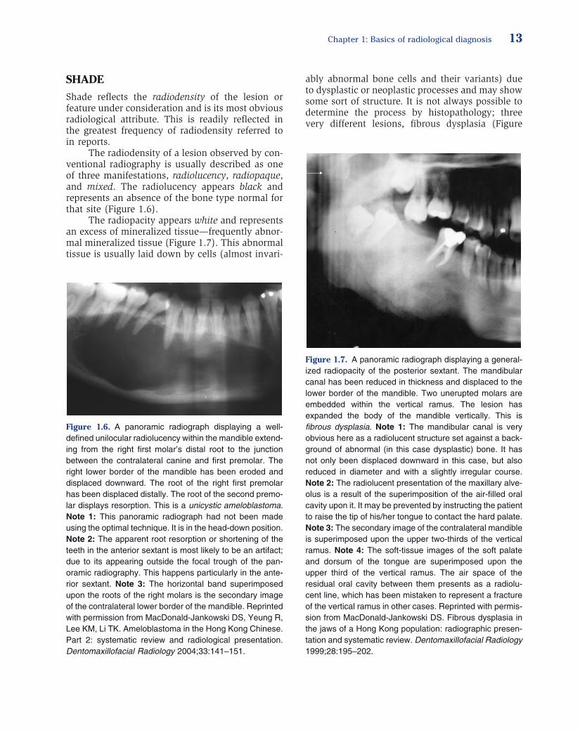
Figure 1.6. A panoramic radiograph displaying a well - defi ned unilocular radiolucency within the mandible extend-ing from the right fi rst molar ’ s distal root to the junction between the contralateral canine and fi rst premolar. The right lower border of the mandible has been eroded and displaced downward. The root of the right fi rst premolar has been displaced distally. The root of the second premo-lar displays resorption. This is a unicystic ameloblastoma . Note 1: This panoramic radiograph had not been made using the optimal technique. It is in the head - down position. Note 2: The apparent root resorption or shortening of the teeth in the anterior sextant is most likely to be an artifact; due to its appearing outside the focal trough of the pan-oramic radiography. This happens particularly in the ante-rior sextant. Note 3: The horizontal band superimposed upon the roots of the right molars is the secondary image of the contralateral lower border of the mandible. Reprinted with permission from MacDonald - Jankowski DS, Yeung R, Lee KM, Li TK. Ameloblastoma in the Hong Kong Chinese. Part 2: systematic review and radiological presentation. Dentomaxillofacial Radiology 2004;33:141 – 151.
Figure 1.7. A panoramic radiograph displaying a general-ized radiopacity of the posterior sextant. The mandibular canal has been reduced in thickness and displaced to the lower border of the mandible. Two unerupted molars are embedded within the vertical ramus. The lesion has expanded the body of the mandible vertically. This is fi brous dysplasia . Note 1: The mandibular canal is very obvious here as a radiolucent structure set against a back-ground of abnormal (in this case dysplastic) bone. It has not only been displaced downward in this case, but also reduced in diameter and with a slightly irregular course. Note 2: The radiolucent presentation of the maxillary alve-olus is a result of the superimposition of the air - fi lled oral cavity upon it. It may be prevented by instructing the patient to raise the tip of his/her tongue to contact the hard palate. Note 3: The secondary image of the contralateral mandible is superimposed upon the upper two - thirds of the vertical ramus. Note 4: The soft - tissue images of the soft palate and dorsum of the tongue are superimposed upon the upper third of the vertical ramus. The air space of the residual oral cavity between them presents as a radiolu-cent line, which has been mistaken to represent a fracture of the vertical ramus in other cases. Reprinted with permis-sion from MacDonald - Jankowski DS. Fibrous dysplasia in the jaws of a Hong Kong population: radiographic presen-tation and systematic review. Dentomaxillofacial Radiology 1999;28:195 – 202.
14 Part 1. Introduction
1.7 ), ossifying fi broma (Figure 1.8 ), and osseous dysplasia (formerly known as cemento - osseous dysplasia) (Figure 1.9 ) are entirely different lesions but display similar histopathological appearances, those of fi bro - osseous lesions . This is discussed in detail in Chapter 10 . Sometimes the bone is not per se abnormal but merely thickened trabeculae as found for idiopathic osteosclerosis (also known as dense bone islands) (Figure 1.10 ).
Occasionally mineralization can also be dys-trophic; this is a deposition of mineral in soft - tissue lesions, such as calcifi cation of lymph nodes (Figure 1.11 ), tonsils (Figure 1.11 ), sialoliths (Figure 13.6 ), antrolith acne scars, and so on. This is not laid down by bone cells but still may display some structure, usually as concentric layers of accretion (Figure 9.16 ).
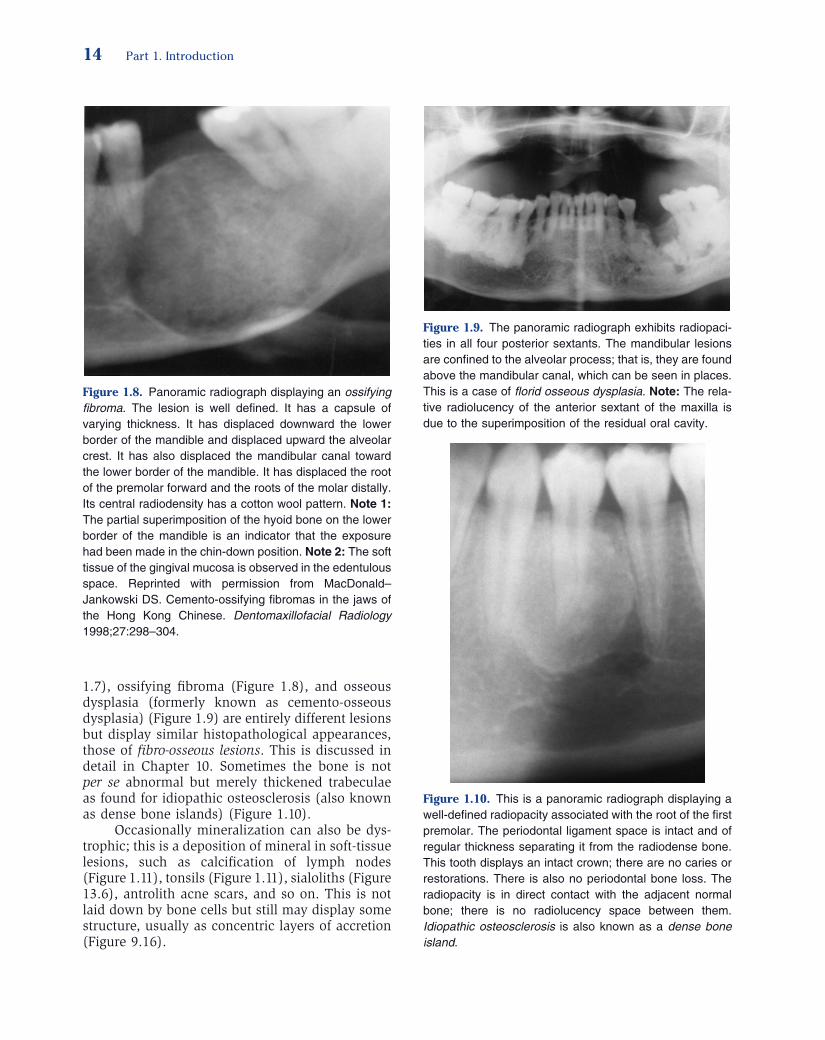
Figure 1.8. Panoramic radiograph displaying an ossifying fi broma . The lesion is well defi ned. It has a capsule of varying thickness. It has displaced downward the lower border of the mandible and displaced upward the alveolar crest. It has also displaced the mandibular canal toward the lower border of the mandible. It has displaced the root of the premolar forward and the roots of the molar distally. Its central radiodensity has a cotton wool pattern. Note 1: The partial superimposition of the hyoid bone on the lower border of the mandible is an indicator that the exposure had been made in the chin - down position. Note 2: The soft tissue of the gingival mucosa is observed in the edentulous space. Reprinted with permission from MacDonald – Jankowski DS. Cemento - ossifying fi bromas in the jaws of the Hong Kong Chinese. Dentomaxillofacial Radiology 1998;27:298 – 304.
Figure 1.9. The panoramic radiograph exhibits radiopaci-ties in all four posterior sextants. The mandibular lesions are confi ned to the alveolar process; that is, they are found above the mandibular canal, which can be seen in places. This is a case of fl orid osseous dysplasia . Note: The rela-tive radiolucency of the anterior sextant of the maxilla is due to the superimposition of the residual oral cavity.
Figure 1.10. This is a panoramic radiograph displaying a well - defi ned radiopacity associated with the root of the fi rst premolar. The periodontal ligament space is intact and of regular thickness separating it from the radiodense bone. This tooth displays an intact crown; there are no caries or restorations. There is also no periodontal bone loss. The radiopacity is in direct contact with the adjacent normal bone; there is no radiolucency space between them. Idiopathic osteosclerosis is also known as a dense bone island .

Chapter 1: Basics of radiological diagnosis 15
Mixed radiodensity describes a lesion pre-senting as a white area/s within a black area (Figure 1.14 ). This generally represents the deposi-tion of mineralized tissue in an area where the bone type normal for that area had been previously removed to create space for the lesion, which sub-sequently undergoes mineralization.
Radiopacities can arise from variants of anatomy such as mineralization of the stylohyoid complex (Figure 1.12 ). The normally (not mineral-ized) soft - tissue structures can be present, of which the easiest to recognize are the tongue and soft palate, on panoramic radiographs and lateral ceph-alograms (Figure 1.12 ). The ear lobe (Figure 1.12 ) is also very frequently apparent. Fractures can result in opacities if the fractured ends overlap (Figure 1.12 ). Incorrect panoramic radiographic technique (head - down) can result in the superim-position of the body of the hyoid on the mandible, resulting in a radiopacity (Figure 1.13 a) instead of its usual submandibular position (Figure 1.13 b).
Figure 1.11. A panoramic radiograph displaying a number of normal and abnormal radiopacities. Structures, which are normally composed of soft tissue, can present as radi-opacities either by being silhouetted against air, as already seen for the soft palate and tongue, or becoming calcifi ed. The latter can occur secondary to an infection. Classically this infection was tuberculosis. The calcifi ed structures are the lymph nodes (cervical jugulodigastric and submandibu-lar nodes) and the palatine tonsil (small opacities superim-posed upon the mandibular foramen). This calcifi cation is dystrophic. Another calcifi ed, but almost always normal structure, is the styloid process. Note 1: The soft palate and tongue are clearly visible. Note 2: The horizontal band of a smeared radiopacity occupying the superior two - thirds of this image represents the contralateral mandible.
Figure 1.12. A panoramic radiograph displaying a normal - sized styloid process (extends no lower than the mandibu-lar foramen; see Chapter 10 for more details) and a calcifi ed stylohyoid ligament reaching the hyoid bone. The lesser horn is presented as a round radiopacity superimposed upon the superior margin of the hyoid bone. These are also normal features. Note 1: The pinna of the ear is superim-posed upon the styoid process. Note 2: The condyle is fractured and displaced anteriorly. As it overlaps the supe-rior vertical ramus, an increased radiopacity occurs at the site of this overlap. Note 3: The black line delineating the line of the fractured condyle represents the Mach band effect and is discussed further in Chapter 3 . Note 4: The soft palate and dorsum of the tongue are in contact and the radiolucent line observed in Figure 1.3 is substantially absent. Note 5: The superior half of the image is occupied by the secondary image of the contralateral mandible.
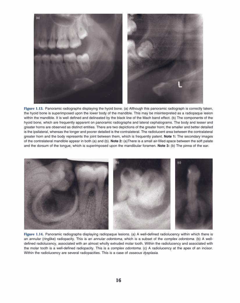
Figure 1.13. Panoramic radiographs displaying the hyoid bone. (a) Although this panoramic radiograph is correctly taken, the hyoid bone is superimposed upon the lower body of the mandible. This may be misinterpreted as a radiopaque lesion within the mandible. It is well defi ned and delineated by the black line of the Mach band effect. (b) The components of the hyoid bone, which are frequently apparent on panoramic radiographs and lateral cephalograms. The body and lesser and greater horns are observed as distinct entities. There are two depictions of the greater horn; the smaller and better detailed is the ipsilateral, whereas the longer and poorer detailed is the contralateral. The radiolucent area between the contralateral greater horn and the body represents the joint between them, which is frequently patent. Note 1: The secondary images of the contralateral mandible appear in both (a) and (b). Note 2: (a)There is a small air - fi lled space between the soft palate and the dorsum of the tongue, which is superimposed upon the mandibular foramen. Note 3: (b) The pinna of the ear.
(a) (b)
Figure 1.14. Panoramic radiographs displaying radiopaque lesions. (a) A well - defi ned radiolucency within which there is an annular (ringlike) radiopacity. This is an annular odontoma , which is a subset of the complex odontoma . (b) A well - defi ned radiolucency, associated with an almost wholly extruded molar tooth. Within the radiolucency and associated with the molar tooth is a well - defi ned radiopacity. This is a complex odontoma . (c) A radiolucency at the apex of an incisor. Within the radiolucency are several radiopacities. This is a case of osseous dysplasia .
(a) (b) (c)
16


