1
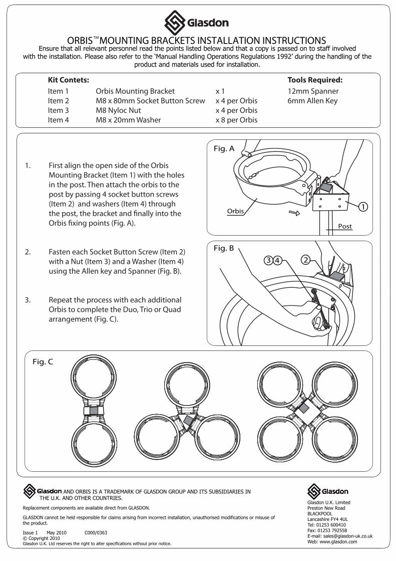
ORBIS MOUNTING BRACKETS INSTALLATION INSTRUCTIONS Ensure that all relevant personnel read the points listed below and that a copy is passed on to staff involved with the installation. Please also refer to the ‘Manual Handling Operations Regulations 1992’ during the handling of the product and materials used for installation. TM Kit Contets: Tools Required: Item 1 Orbis Mounting Bracket x 1 12mm Spanner Item 2 M8 x 80mm Socket Button Screw x 4 per Orbis 6mm Allen Key Item 3 M8 Nyloc Nut x 4 per Orbis Item 4 M8 x 20mm Washer x 8 per Orbis AND ORBIS IS A TRADEMARK OF GLASDON GROUP AND ITS SUBSIDIARIES IN THE U.K. AND OTHER COUNTRIES. Replacement components are available direct from GLASDON. GLASDON cannot be held responsible for claims arising from incorrect installation, unauthorised modifications or misuse of the product. Issue 1 May 2010 C000/0363 © Copyright 2010 Glasdon U.K. Ltd reserves the right to alter specifications without prior notice. Glasdon U.K. Limited Preston New Road BLACKPOOL Lancashire FY4 4UL Tel: 01253 600410 Fax: 01253 792558 E-mail: [email protected] Web: www.glasdon.com 1. First align the open side of the Orbis Mounting Bracket (Item 1) with the holes in the post. Then attach the orbis to the post by passing 4 socket button screws (Item 2) and washers (Item 4) through the post, the bracket and finally into the Orbis fixing points (Fig. A). 2. Fasten each Socket Button Screw (Item 2) with a Nut (Item 3) and a Washer (Item 4) using the Allen key and Spanner (Fig. B). 3. Repeat the process with each additional Orbis to complete the Duo, Trio or Quad arrangement (Fig. C). Fig. A Fig. B Fig. C Orbis Post 1 3 2 4