PIONEER ELECTRONIC CORPORATION 4-1, Meguro 1-Chome, Meguro-ku, Tokyo 153-8654, Japan PIONEER ELECTRONICS SERVICE INC. P.O.Box 1760, Long Beach, CA 90801-1760 U.S.A. PIONEER ELECTRONIC [EUROPE] N.V. Haven 1087 Keetberglaan 1, 9120 Melsele, Belgium PIONEER ELECTRONICS ASIACENTRE PTE.LTD. 253 Alexandra Road, #04-01, Singapore 159936 C PIONEER ELECTRONIC CORPORATION 1998 K-ZZB. DEC. 1998 Printed in Japan ORDER NO. CRT2265 HIGH POWER CASSETTE PLAYER WITH FM/MW/LW TUNER KEH-1800 X1M/EW Service Manual CONTENTS 1. SAFETY INFORMATION ............................................2 2. EXPLODED VIEWS AND PARTS LIST ......................2 3. SCHEMATIC DIAGRAM...........................................10 4. PCB CONNECTION DIAGRAM................................18 5. ELECTRICAL PARTS LIST........................................26 6. ADJUSTMENT .........................................................31 7. GENERAL INFORMATION.......................................33 7.1 PARTS ................................................................33 7.1.1 IC ...............................................................33 7.1.2 DISPLAY ...................................................37 7.2 DISASSEMBLY ..................................................38 7.3 BLOCK DIAGRAM .............................................39 8. OPERATIONS AND SPECIFICATIONS ....................40 KEH-1830 X1M/EW NOTE: - See the separate manual CX-644(CRT1800) for the cassette mechanism description. - The cassette mechanism assy employed in this model is one of 2M series. KEH-1800/X1M/EW
Transcript
PIONEER ELECTRONIC CORPORATION 4-1, Meguro 1-Chome, Meguro-ku, Tokyo 153-8654, Japan PIONEER ELECTRONICS SERVICE INC. P.O.Box 1760, Long Beach, CA 90801-1760 U.S.A.PIONEER ELECTRONIC [EUROPE] N.V. Haven 1087 Keetberglaan 1, 9120 Melsele, Belgium PIONEER ELECTRONICS ASIACENTRE PTE.LTD. 253 Alexandra Road, #04-01, Singapore 159936
C PIONEER ELECTRONIC CORPORATION 1998 K-ZZB. DEC. 1998 Printed in Japan
8. OPERATIONS AND SPECIFICATIONS....................40
KEH-1830 X1M/EW
NOTE:
- See the separate manual CX-644(CRT1800) for the cassette mechanism description.
- The cassette mechanism assy employed in this model is one of 2M series.
KEH-1800/X1M/EW
2
KEH-1800,1830
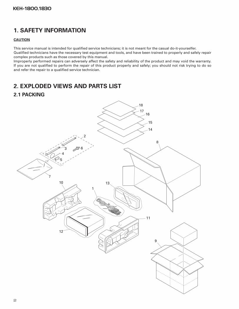
2. EXPLODED VIEWS AND PARTS LIST
2.1 PACKING
2
5
43
7
10
1
13
12
11
9
8
1617
14
15
6
18
1. SAFETY INFORMATION
CAUTION
This service manual is intended for qualified service technicians; it is not meant for the casual do-it-yourselfer.Qualified technicians have the necessary test equipment and tools, and have been trained to properly and safely repaircomplex products such as those covered by this manual.Improperly performed repairs can adversely affect the safety and reliability of the product and may void the warranty.If you are not qualified to perform the repair of this product properly and safely; you should not risk trying to do soand refer the repair to a qualified service technician.
26 Holder CNC621627 Heat Sink CNC621728 •••••29 Holder CNC684530 Chassis Unit See Contrast table(2)
31 Holder Unit CXB268732 Button CAC483633 Spring CBH183434 Spring CBH183535 Spring CBH1996
36 Bracket CNC613537 Bracket CNC679138 Arm CNV469239 Arm CNV469340 Arm CNV4728
41 Panel Unit See Contrast table(2)42 Door See Contrast table(2)43 Spring CBH183844 Panel See Contrast table(2)45 Screw IMS20P030FZK
46 Detach Grille Assy See Contrast table(2)47 Screw BPZ20P120FZK48 Button(Detachable) See Contrast table(2)49 Button(Eject) See Contrast table(2)50 Button(REW) See Contrast table(2)
51 Button(FF) See Contrast table(2)52 Button(F,A,Cross) See Contrast table(2)53 Button(-,-) See Contrast table(2)54 Button(1-6,D,B) See Contrast table(2)55 Button(+,-) See Contrast table(2)
56 Button(SO/OFF,PGM) See Contrast table(2)57 Spring CBH183658 Spring CBH210359 Grille See Contrast table(2)60 Cover See Contrast table(2)
61 Keyboard Unit See Contrast table(2)62 LCD(LCD901) CAW151363 Connector(CN901) CKS358064 Holder CNC805465 Connector CNV5586
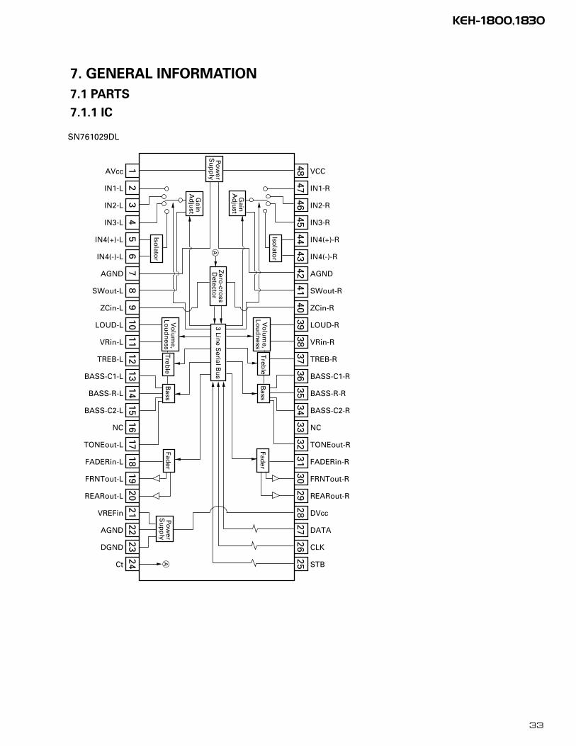
- Pin Functions(PE5017B)Pin No. Pin Name I/O Format Function and Operation
1,2 NC Not used3 ADPW A/D converter power4 GND GND
5,6 NC Not used7 AVREF1 (Connect to VDD)8 KYDT I Key data input9 DPDT O C Display data output
10 dsens I Grille detach sense input11 TUNPDI I PLL IC data input12 TUNPDO O C PLL IC data output13 TUNPCK O C PLL IC clock output14 TUNPCE O C PLL IC chip enable output
15-21 NC Not used22 swvdd O C Grille power supply control output23 NC Not used24 VDT O C Data output for electronic volume25 VCK O C Clock output for electronic volume26 VST O C Strobe pulse output for electronic volume27 SYSPW O C System power supply control output28 mute O C System mute output29 DMINH O C Mechanism mute cancel output
30–32 NC Not used33 GND GND
34–37 NC Not used38 FM O C FM power control output39 AM O C AM power control output
40–49 NC Not used50 eject I Eject key input51 tapld I Tape loading input52 MECPW O C Cassette mechanism power output53 mcmut I Mechanism mute input54 NOR/rev I Normal reverse input
55-59 NC Not used60 reset I Reset input
61,62 NC Not used63 CLKIN I Clock input64 asens I ACC power sense input65 bsens I Back up power sense input66 SD I SD input 67 st I FM stereo input68 VDD Power supply69 X2 Oscillator output70 X1 Oscillator input71 GND GND72 NC Not used73 TESTIN I Test program mode input74 AVDD A/D converter analog power supply (VDD)75 AVREF0 (A/D converter standard voltage input)76 SL I Signal level input77 MODEL I Model select input
78–80 NC Not used
35
KEH-1800,1830
- Pin Functions (PD6293A)Pin No. Pin Name I/O Function and Operation
1–5 SEG4-0 O LCD segment output 4-06–8 COM1-3 O Common driver output 1-3
9 COM0 O Common driver output 010 LCDB LCD bias power supply
11–14 KS3-0 O Key strobe output 3-015,16 KDT0,1 I Key data input 0,1
17 REM I Remote control reception18 DPDT I Display data input19 NC Not used20 KYDT O Key data output21 MODA GND22 X0 Crystal oscillator connection pin23 X1 Crystal oscillator connection pin24 VSS GND
25,26 KDT2,3 I Key data input 2,327,28 KST5,4 O Key strobe output 5,429–55 SEG39-13 O LCD segment output 39-13
56 VCC 5V57–64 SEG12-5 O LCD segment output 12-5
IC's marked by* are MOS type.
Be careful in handling them because they are very
liable to be damaged by electrostatic induction.
801
20
21 40
41
60
61
*PE5017B
Format Meaning
C C MOS
*PD6293A
49
4833
32
17
16 1
64
36
KEH-1800,1830
PA4023B
37
KEH-1800,1830
7.1.2 DISPLAY
- CAW1513S
EG
ME
NT
CO
MM
ON
38
KEH-1800,1830
7.2 DISASSEMBLY
- Removing the Tuner Amp Unit(Fig.2)
Removing the two screws.
Removing the three screws.
Removing the screw.
Unbend the tabs at four locations indicated
by arrow until straight.
Remove the Tuner Amp Unit.
- Removing the Case(not shown)
1.Remove the three screws.
2.Remove the Case.
- Removing the Cassette Mechanism Assy
(not shown)
1.Remove the four screws.
2.Disconnect the connector, and then removing the
Cassette Mechanism Assy.
- Removing the Panel Unit(Fig.1)
Disengage the stopper at two locations
indicated
Remove the Panel Unit.
Fig.1
Fig.2
Panel Unit
Tuner Amp Unit
39
KEH-1800,1830
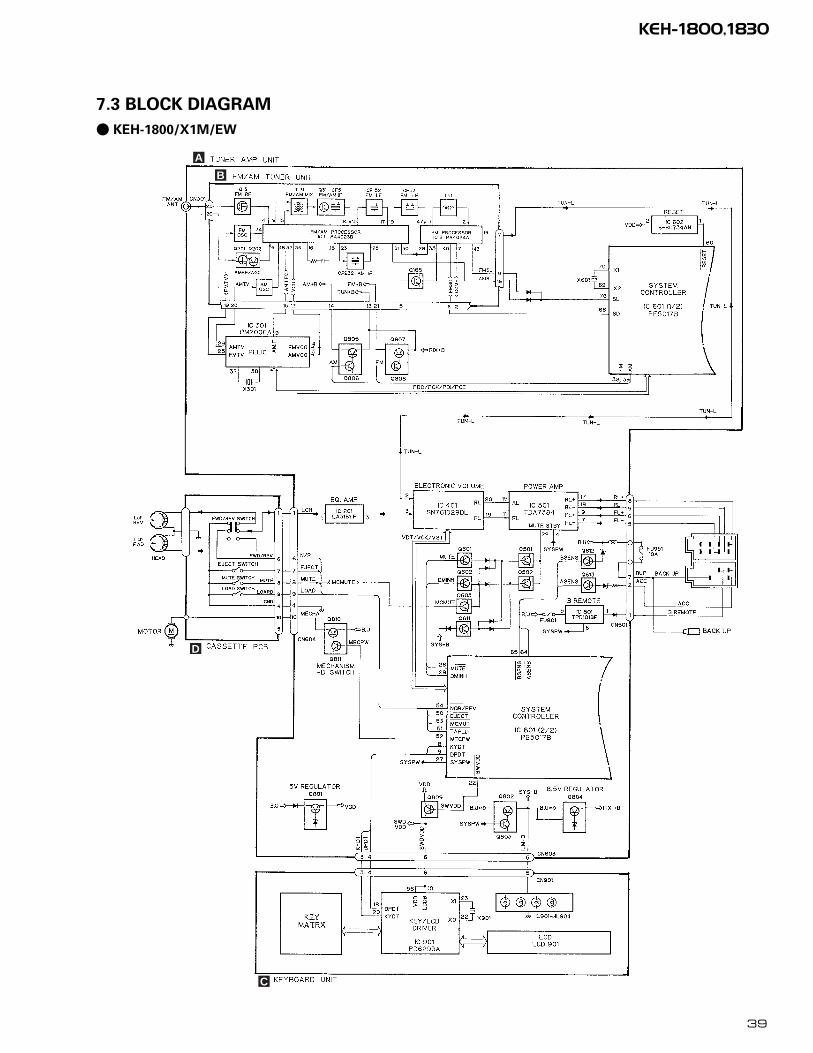
7.3 BLOCK DIAGRAM
- KEH-1800/X1M/EW
A
B
D
C
40
KEH-1800,1830
8. OPERATIONS AND SPECIFICATIONS1.
Th
isU
nit
2.A
nte
nn
aja
ck
3.C
on
nec
tle
ads
of
the
sam
eco
lor
toea
cho
ther
.
5.C
ap
6.Ye
llow
Tote
rmin
alal
way
ssu
pp
lied
wit
hp
ow
er7.
Yello
wB
ack-
up
(or
acce
sso
ry)
8.R
edTo
elec
tric
term
inal
con
tro
lled
by
ign
itio
nsw
itch
(12
VD
C)
ON
/OFF
.9.
Red
Acc
esso
ry(o
rB
ack-
up
)
5
67
89
No
te:
Dep
end
ing
on
the
kin
do
fve
hic
le,t
he
fun
ctio
no
f7
and
9m
ayb
ed
iffe
ren
t.If
this
isth
eca
se,b
esu
reto
con
nec
t6
to9
and
7to
8.W
hen
the
po
wer
cord
of
the
oth
erp
rod
uct
isco
nn
ecte
dto
term
inal
5,ch
eck
the
fun
ctio
no
fth
ete
rmin
al5
(Bac
ku
po
rA
cces
sory
)b
efo
reh
and
.
4.
11.IS
Oco
nn
ecto
rN
ote
:In
som
eve
hic
les,
the
ISO
con
nec
tor
may
be
div
ided
into
two
.If
this
isth
eca
se,b
esu
reto
con
nec
tto
bo
thco
nn
ecto
rs.
12.S
pea
ker
lead
sW
hit
e:Fr
on
tle
ft+
Wh
ite/
bla
ck:F
ron
tle
ft≠
Gra
y:Fr
on
tri
gh
t+
Gra
y/b
lack
:Fro
nt
rig
ht
≠G
reen
:Rea
rle
ft+
Gre
en/b
lack
:Rea
rle
ft≠
Vio
let:
Rea
rri
gh
t+
Vio
let/
bla
ck:R
ear
rig
ht≠
13.B
lue/
wh
ite
ToA
uto
-an
ten
na
rela
yco
ntr
olt
erm
inal
.(M
ax.3
00m
A12
VD
C)
10.B
lack
Tove
hic
le(m
etal
)b
od
y.
14.F
use
CAU
TIO
N•
Co
rds
for
this
un
it a
nd
th
ose
fo
r o
ther
un
its
may
be
dif
fere
nt
colo
rs e
ven
if t
hey
hav
e th
e sa
me
fun
ctio
n.
Wh
en c
on
nec
tin
g t
his
un
it t
o a
no
ther
un
it, r
efer
to
the
sup
plie
d In
stal
lati
on
man
ual
s o
f b
oth
un
its
and
con
nec
t co
rds
that
hav
e th
e sa
me
fun
ctio
n.
Conn
ectio
n D
iagr
am
41
KEH-1800,1830
Key
Fin
der
Cas
sette
door
Eje
ctbu
tton
LO
UD
butto
n
CL
OC
Kbu
tton
Func
tion
butto
n
SOU
RC
Ebu
tton
+/–
butto
ns
AU
DIO
butto
n
BA
ND
butto
n
But
tons
1–6
AT
Tbu
tton
Det
ach
butto
n
Prog
ram
mab
lebu
tton
5/∞
/2/3
butto
ns
!/⁄
butto
ns
Usi
ng th
e C
asse
tte P
laye
r
Bas
ic O
pera
tion
of C
asse
tte P
laye
r
1.In
sert
the
cas
sett
e ta
pe.
2.Sw
itch
tap
e pl
ayba
ck f
rom
sid
e A
to
side
B, o
r vi
ce v
ersa
.
3.R
aise
or
low
er t
he v
olum
e.
4.R
emov
e th
e ca
sset
te t
ape.
Not
e:•
The
Tap
e fu
nctio
n ca
n be
turn
ed O
N/O
FF w
ith th
e ca
sset
te ta
pe r
emai
ning
in th
ispr
oduc
t.
Sam
e T
ime
42
KEH-1800,1830
Tun
er O
pera
tion
Bas
ic O
pera
tion
of T
uner
1.Se
lect
Tun
er.
The
pro
gram
ser
vice
nam
e or
fre
quen
cy a
ppea
rs o
n th
e di
spla
y.(“
ST
ER
EO
” in
dica
tor
light
s w
hen
a st
ereo
sta
tion
is s
elec
ted.
)
2.Se
lect
the
des
ired
ban
d.
3.Tu
ne t
he r
ecei
ver
to a
hig
her
or lo
wer
fre
quen
cy.
Thi
s pr
oduc
t’s tu
ner
lets
you
sel
ect t
he tu
ning
by
chan
ging
the
leng
th o
f th
etim
e yo
u pr
ess
the
butto
n.
Man
ual T
unin
g (s
tep
by s
tep)
0.3
seco
nds
or le
ss
Seek
Tun
ing
0.3
– 2
seco
nds
Man
ual T
unin
g (c
ontin
uous
ly)
2 se
cond
s or
mor
e
Not
e:•
To s
elec
t a w
eak
broa
dcas
ting
stat
ion
that
can
not b
e tu
ned
in w
ith th
e Se
ekT
unin
g fu
nctio
n, tu
ne in
with
Man
ual T
unin
g.
FI=
FII=
FIII
=M
W/L
W
Eac
h pr
ess
chan
ges
the
Sour
ce ..
.
4.R
aise
or
low
er t
he v
olum
e.
5.Tu
rn t
he s
ourc
e O
FF.
Hol
d fo
r 1
seco
nd
43
KEH-1800,1830
Aud
io A
djus
tmen
t
Sele
ctin
g th
e M
ode
•Se
lect
the
mod
e yo
u w
ant
to a
djus
t.
Eac
h pr
ess
of th
e A
UD
IO b
utto
n se
lect
s th
e m
ode
in th
e fo
llow
ing
orde
r:Fa
der/
Bal
ance
=B
ass
=T
rebl
e =
Lou
dnes
s
Whe
n au
dio
mod
es a
re s
elec
ted
for
adju
stm
ent,
the
setti
ng r
etur
ns to
the
norm
al d
ispl
ay a
fter
30
seco
nds.
Bal
ance
Adj
ustm
ent
Thi
s fu
nctio
n al
low
s yo
u to
sel
ect a
Fad
er/B
alan
ce s
ettin
g th
at p
rovi
des
idea
l lis
teni
ng c
ondi
tions
in a
ll oc
cupi
ed s
eats
.
1.Se
lect
the
Fad
er/B
alan
ce m
ode.
Aft
er a
djus
tmen
t use
the
BA
ND
but
ton
to r
etur
n to
the
norm
al d
ispl
ay.
2.Sh
ift
the
bala
nce
prog
ress
ivel
y to
the
fro
nt o
r re
ar s
peak
ers.
“FA
D F
15”
– “F
AD
R15
” is
dis
play
ed a
s it
mov
es f
rom
fro
nt to
rea
r.
Not
e:•
“FA
D 0
0” is
the
prop
er s
ettin
g w
hen
2 sp
eake
rs a
re in
use
.
3.Sh
ift
the
bala
nce
to t
he le
ft o
r ri
ght
spea
ker,
res
pect
ivel
y.
“BA
L L
9” –
“B
AL
R9”
is d
ispl
ayed
as
it m
oves
fro
m le
ft to
rig
ht.
Eac
h pr
ess
chan
ges
the
Mod
e ...
Aud
io A
djus
tmen
t
Bas
s/Tr
eble
Adj
ustm
ent
Thi
s pr
oduc
t is
equi
pped
with
two
tone
adj
ustm
ent m
odes
, the
Bas
sA
djus
tmen
t and
Tre
ble
Adj
ustm
ent m
odes
.
1.Se
lect
“B
ass
Adj
ustm
ent
mod
e” o
r “T
rebl
e A
djus
tmen
t m
ode”
.A
fter
adj
ustm
ent u
se th
e B
AN
D b
utto
n to
ret
urn
to th
e no
rmal
dis
play
.
2.In
crea
se o
r de
crea
se t
he in
tens
ity
of t
he b
ass
or t
rebl
e,w
hich
ever
is s
elec
ted.
The
dis
play
sho
ws
“+6”
–“–
6”.
3.R
epea
t st
eps
1 –
2 ab
ove
for
the
othe
r B
ass
or T
rebl
eA
djus
tmen
t m
ode.
Loud
ness
Adj
ustm
ent
The
Lou
dnes
s fu
nctio
n co
mpe
nsat
es f
or d
efic
ienc
ies
in th
e lo
w a
nd h
igh
soun
d ra
nges
at l
ow v
olum
e.
1.Se
lect
the
Lou
dnes
s ad
just
men
t m
ode.
Aft
er s
elec
tion
use
the
BA
ND
but
ton
to r
etur
n to
the
norm
al d
ispl
ay.
2.Sw
itch
the
Lou
dnes
s fu
ncti
on O
N o
r O
FF.
Volu
me
Atte
nuat
orT
he a
ttenu
ator
red
uces
the
volu
me
inst
antly
.
•C
ut t
he v
olum
e by
abo
ut 9
0%.
Rep
eat t
he p
rece
ding
ope
ratio
n to
ret
urn
to p
revi
ous
volu
me.
If th
e (+
) or
(–)
but
ton
is u
sed
to c
ance
l the
Atte
nuat
or m
ode,
the
soun
d w
ill r
esum
e at
a lo
wer
volu
me
than
bef
ore.
“LO
UD
”
KEH-1800,1830
Specifications
GeneralPower source .......... 14.4 V DC (10.8 – 15.1 V allowable)Grounding system ........................................ Negative typeMax. current consumption ........................................ 8.5 ADimensions