E. Armstrong Department of Chemistry University College Cork Cork , Ireland
Dr. W. Khunsin Nanotechnology Research CenterResearch Institute for Electronic Science Hokkaido University 001–0021 , Sapporo , Japan
M. Osiak Department of Chemistry University College Cork Cork , Ireland
M. Blömker Department of Chemical Engineering Münster University of Applied Sciences Stegerwaldstraße 39, 48565 , Steinfurt , Germany
Prof. C. M. S. Torres Catalan Institute of Nanoscience and Nanotechnology ICN2 Campus UAB, Edifi ci ICN2, 08193 Bellaterra Spain and Catalan Institute for Research and Advanced Studies (ICREA) 08010 , Barcelona , Spain
Dr. C. O’Dwyer Department of Chemistry University College Cork Cork, Ireland and Micro & Nanoelectronics Centre Tyndall National Institute Lee Maltings, Cork Ireland and Materials & Surface Science Institute University of Limerick Limerick , Ireland E-mail: [email protected]
emitters and the performance of photonic crystal based gas
sensors. [ 29,30 ] Furthermore, this hybrid system fi nds benefi cial
applications as templates for the fabrication of high-power,
high rate battery electrodes, [ 8 ] and as substrates for surface-
enhanced Raman scattering (SERS) measurements, since
the template that is eventually infi lled is directly connected
to the current collector (substrate). [ 31 ] However, coating of
gold substrates with colloidal crystals is not favourable under
ambient conditions. This is because a clean gold substrate,
free of any type of contaminants and naturally hydrophilic,
quickly turns hydrophobic even with just a monolayer of car-
bonaceous contamination. [ 32 ] As such, when in contact with
air as in the most commonly used crystallization methods, the
resulting structures are in most cases disordered crystals or
amorphous structures.
Here, we show that surfactant functionalization of
poly(methylmethacrylate) (PMMA) spheres of 700 nm in
diameter allows a highly ordered 2D colloidal photonic
crystal (PhC) to form on a gold surface, rather than glass
substrates, by dip-coating at rates between 20 and 40 times
faster than previously reported. [ 24,25 ] In the absence of the
surfactant, however, an amorphous, potentially uncorrelated,
overlapping opal fi lm is formed. In addition, we demonstrate
how to achieve a multi-layer colloidal crystal template with
a similar light scattering ability and coverage during coating
at slower rate of withdrawal, using a lower concentration of
spheres and surfactant. As will be shown, surfactant-assisted
dip-coating provides a route to high quality ordered 2D or
3D colloidal crystals or templates directly on metallic sur-
faces at fast dip-coating rates.
The method is made possible by using sodium dodecyl
sulphate, which is an amphiphilic anion that dissociates in
water to form charged monomers. At a suffi ciently high con-
centration, greater than the critical micelle concentration
(CMC), these monomers orientate their hydrophilic heads
towards the polar solute, and their hydrophobic tails group
together to form a hydrophobic core. These particles, known
as micelles are known to enhance certain aspects of a solu-
tion such as the solubility of hydrophobic materials, and alter
other aspects such as viscosity and polarity. [ 33 ] In our experi-
ment, SDS was used at room temperature and at a concen-
tration of 8 mg mL −1 , above the theoretical CMC for SDS
of 2.3 mg mL −1 (8.0 × 10 −3 mol dm −3 ). [ 34 ] Figure 1 (a) summa-
rizes the dip coating of PMMA PhC monolayers and Figure 1
(1–3) illustrates the possible orientations of the SDS additive
either in micellular and/or monomer form. At concentrations
below CMC monomers of SDS are known to arrange along
the water-air interface (Figure 1 –1) but at the concentration
level used in our experiment micellization of the SDS within
solution takes precedence (Figure 1 –2). At this point a transi-
tion from monomeric to micellized surfactant occurs where
both micelles and monomers co-exist within the solution [ 35,36 ]
and any surfactant above CMC will lead to the formation
of micelles. [ 37 ] The full details and mechanisms for the SDS
small 2014, DOI: 10.1002/smll.201303616
Figure 1. (a) Diagram depicting the deposition mechanism of opal spheres by dip coating at a withdrawal rate of 1 mm/min. (1–4) Schematic representation of micellular SDS and functionalized PMMA and optical images of the angle-dependent scattering seen from PhC deposits formed using SDS. (b) SEM image and corresponding FFTs showing a 2D photonic glass monolayer (without SDS) and (c) a 2D monolayer photonic crystal (with SDS) and (d) and (e) are the FFT intensity profi les from (b) and (c) respectively. Profi les in (e) were acquired along the [100] and [110] directions, corresponding to the ΓX and ΓL directions in the Brilluoin zone of a 2D hexagonal lattice.
Ordered 2D Colloidal Photonic Crystals on Gold Substrates by Surfactant-Assisted Fast-Rate Dip Coating
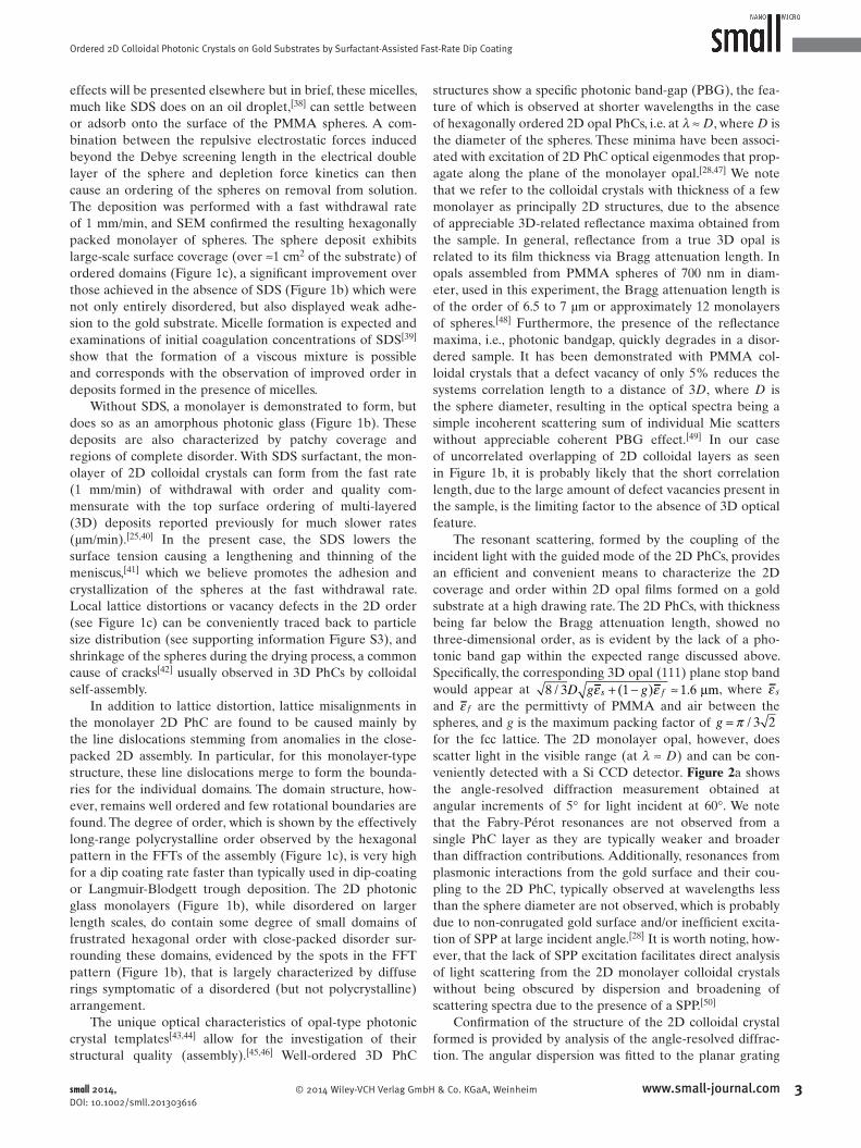
equation, [sin( ) sin( )]d xλ α β= + + , where α is the angle
of incidence, β is the angle of diffraction, d is the effective
grating groove, which in this case corresponds to 32
D, the
half period of the trigonal lattice for the wave vector of inci-
dent light propagating along the ΓΚ direction in the Brillouin
zone of a 2D hexagonal lattice. This is schematically repre-
sented in Figure 2 (b), where D is the sphere diameter, and
x is the deviation half-angle between incident and diffracted
beams defi ned according to ( ) ( ) 2xα λ β λ= + . Figure 2 b shows
the theoretical dispersion (blue line) calculated using the
equation above with the nominal diameter of 700 nm for the
spheres, as determined by SEM and dynamic light scattering,
as an input parameter. The fi tting procedure gives x ≈ 10.57,
the result of which is plotted against the experimental dis-
persions (black circles) taken from the experimental spectra
shown in Figure 2 a. The red dashed line indicates the ‘best fi t’
theoretical dispersion i.e. when the diameter of the spheres is
not fi xed at 700 nm. This calculation suggests a slight increase
in the diameter of the spheres which could be related to the
SDS addition and its presence around the spheres (see sup-
porting information Figure S4).
Figure 2 (c) shows the light scattering behaviour for a
fast-rate dip-coated 2D PhC monolayer formed with SDS
surfactant at a diffraction angle of 0°, i.e. normal to the sub-
strate, for light incident at 60°, and is compared to the same
response for the photonic glass deposit in the absence of
SDS (black line). In this latter case, no 2D scattering was
observed. The scattering spectra of the PhC monolayer (red
line) formed in the presence of SDS exhibited well-defi ned
scattering characteristic of a 2D colloidal crystal at a reduced
wavelength of D /λ = 1.13, close to the scattering resonance
condition for the monolayer opal. The disordered monolayer
breaks the Bragg scattering condition, causing additional
background scattering components, which can be observed as
a broadband, low-intensity peak shown in Figure 2 c. The pro-
fi le does follow somewhat the diffraction of the ordered 2D
opal and is likely due to the small degree of ordering within
several domains (see Figure 1 b).
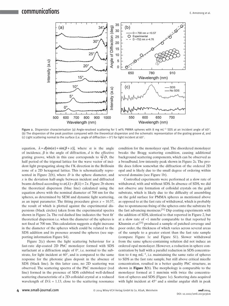
Controlled experiments were performed at a slow rate of
withdrawal, with and without SDS. In absence of SDS, we did
not observe any formation of colloidal crystals on the gold
substrate, which is likely due to the diffi culty of assembling
on the gold surface for PMMA spheres as mentioned above
as opposed to at the fast rate of withdrawal, which is probably
due to spontaneous fi xing of the spheres onto the substrate by
the fast advancing meniscus. [ 51 ] Dip coating experiments with
the addition of SDS, identical to that reported in Figure 2 , but
at a slow rate of ≈1 mm/hr comparable to that reported by
Khunsin et al. [ 25 ] produced a sample of patched coverage and
poor order, the thickness of which varies across several areas
of the sample to a greater extent than the fast rate sample
(compare Figure 1 c and Figure S1). Slower withdrawal
from the same sphere-containing solution did not induce an
ordered opal monolayer. However, a reduction in sphere con-
centration by half with a parallel reduction in SDS concentra-
tion to 4 mg mL −1 , i.e. maintaining the same ratio of spheres
to SDS as the fast rate sample, but still above critical micelle
concentration, resulted in a better quality PhC structure, as
shown in Figure 3 (b). The morphology is comparable to the
monolayer formed at 1 mm/min with twice the concentra-
tion of spheres and SDS (Figure 1 c). Scattering data acquired
with light incident at 45° and a similar angular shift in peak
small 2014, DOI: 10.1002/smll.201303616
Figure 2. Dispersion characterisation (a) Angle-resolved scattering for 5 wt% PMMA spheres with 8 mg mL −1 SDS at an incident angle of 60°. (b) The dispersion of the peak position compared with the theoretical dispersion and the schematic representation of the grating groove d , and (c) Light scattering normal to the surface (i.e. angle of diffraction = 0°) for light incident at 60°.
Ordered 2D Colloidal Photonic Crystals on Gold Substrates by Surfactant-Assisted Fast-Rate Dip Coating
position was measured indicating the presence of 2D order
within the template, as shown in Figure 3 (a). A comparison of
the scattering from the fast and slow rate 2D PhCs for light
incident at the same angle 45° is shown in Figure 3 (c), where
the scattering peak for the fast rate sample is located at a
wavelength of D /λ = 1.13, whereas that of a deposit formed
with half the concentration of spheres and SDS is located at
D /λ = 1.2. We note that the scattering peak for the fast rate
sample is ≈15% broader than the 2D PhC formed at the slow
rate, which indicates a lesser degree of order in the fast rate
sample. This might be due to larger crystal lattice distortion
from dislocations and/or concentration gradients, i.e. non-
uniform distribution of the spheres, and contributions from
wider spaces between spheres in the case of fast rate sample
with double the concentration of spheres and SDS. [ 52 ] It is
noted, however, that the PhC achieved for the slow rate with
reduced concentration is not a single monolayer of spheres as
seen for the faster rate sample; the increase in thickness while
not suffi cient to produce a 3-dimensional structure provides
an environment that is more conducive to crystallization of
the spheres, [ 25 ] leading to extended long-range order for this
slow rate sample and explains the lower relative bandwidth
(Δλ/λ) of 0.052 compared with that of 0.067 for the fast rate
dip-coated PhC (Figure 3 c).
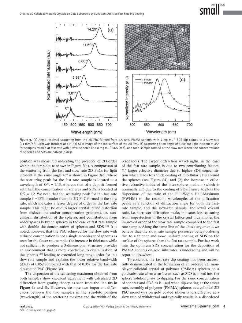
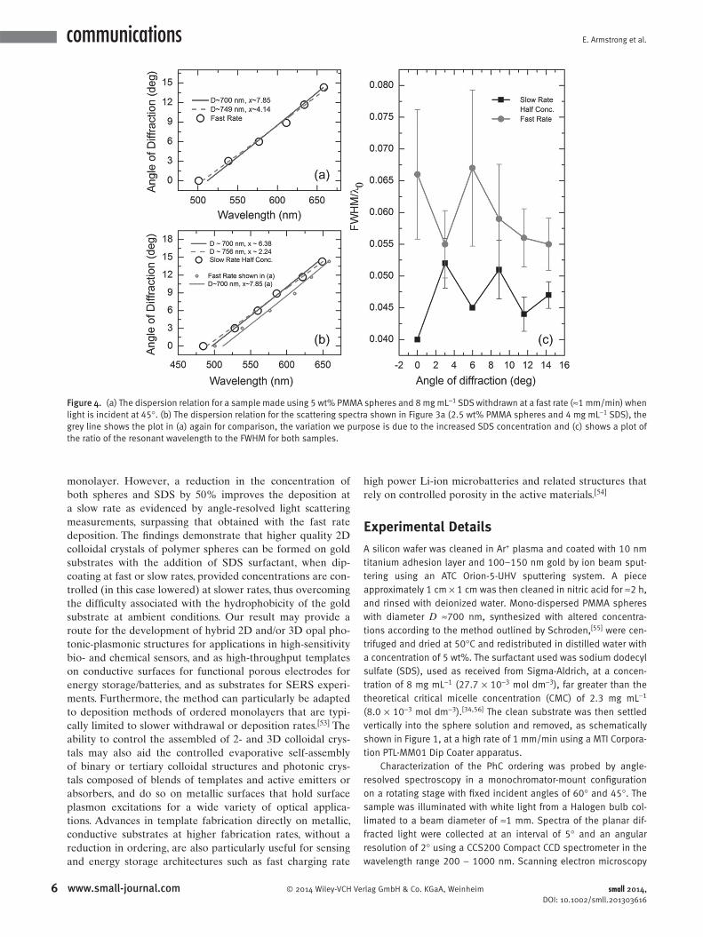
The dispersion of the scattering maximum obtained from
both samples show excellent agreement with calculated 2D
diffraction from grating theory, as seen from the line fi ts in
Figure 4 a and 4 b. However, we note two important differ-
ences between the two samples in the absolute position
(wavelength) of the scattering maxima and the width of the
resonances. The larger diffraction wavelengths, in the case
of the fast rate sample, is due to two contributing factors:
(1) larger effective diameter due to higher SDS concentra-
tion which leads to a thick coating of micellular SDS around
the spheres (see Figure S4), and (2) the increase in effec-
tive refractive index of the inter-sphere medium (which is
nominally air) due to the coating of SDS. Figure 4 c plots the
dispersions of the ratio of the Full-Width Half-Maximum
(FWHM) to the resonant wavelengths of the diffraction
peaks as a function of diffraction angle for both the fast-
rate sample, and the slow-rate sample. The lower overall
ratio, i.e. narrower diffraction peaks, indicates less scattering
from imperfection in the crystal lattice and thus implies the
improved order of the slow rate sample compared to the fast
rate sample. Along the same line of the above arguments, we
believe that the slow rate sample possesses better ordering
due to a thinner and more uniform coating of SDS on the
surface of the spheres than the fast rate sample. Further work
into the optimum SDS concentration for the deposition of
PMMA spheres on gold substrates is undergoing and will be
reported elsewhere.
To conclude, the fast-rate dip coating has been success-
fully demonstrated in the formation of an ordered 2D mon-
olayer colloidal crystal of polymer (PMMA) spheres on a
gold substrate when a surfactant such as SDS is mixed into the
sphere solution prior to dipping. For the same concentration
of spheres and SDS as is used when dip-coating at the faster
rate, assembly of polymer (PMMA) spheres as a colloidal 2D
PhC monolayer on gold coated silicon is less effective at a
slow rate of withdrawal and typically results in a disordered
small 2014, DOI: 10.1002/smll.201303616
Figure 3. (a) Angle resolved scattering from the 2D PhC formed from 2.5 wt% PMMA spheres with 4 mg mL −1 SDS dip coated at a slow rate (≈1 mm/hr). Light was incident at 45°. (b) SEM image of the top surface of the 2D PhC. (c) Scattering at an angle of 8.88° for light incident at 45° for samples formed at fast rate with 5 wt% spheres and 8 mg mL −1 SDS (red), and for a sample formed at the slow rate where the concentrations of spheres and SDS are halved (black).
monolayer. However, a reduction in the concentration of
both spheres and SDS by 50% improves the deposition at
a slow rate as evidenced by angle-resolved light scattering
measurements, surpassing that obtained with the fast rate
deposition. The fi ndings demonstrate that higher quality 2D
colloidal crystals of polymer spheres can be formed on gold
substrates with the addition of SDS surfactant, when dip-
coating at fast or slow rates, provided concentrations are con-
trolled (in this case lowered) at slower rates, thus overcoming
the diffi culty associated with the hydrophobicity of the gold
substrate at ambient conditions. Our result may provide a
route for the development of hybrid 2D and/or 3D opal pho-
tonic-plasmonic structures for applications in high-sensitivity
bio- and chemical sensors, and as high-throughput templates
on conductive surfaces for functional porous electrodes for
energy storage/batteries, and as substrates for SERS experi-
ments. Furthermore, the method can particularly be adapted
to deposition methods of ordered monolayers that are typi-
cally limited to slower withdrawal or deposition rates. [ 53 ] The
ability to control the assembled of 2- and 3D colloidal crys-
tals may also aid the controlled evaporative self-assembly
of binary or tertiary colloidal structures and photonic crys-
tals composed of blends of templates and active emitters or
absorbers, and do so on metallic surfaces that hold surface
plasmon excitations for a wide variety of optical applica-
tions. Advances in template fabrication directly on metallic,
conductive substrates at higher fabrication rates, without a
reduction in ordering, are also particularly useful for sensing
and energy storage architectures such as fast charging rate
high power Li-ion microbatteries and related structures that
rely on controlled porosity in the active materials. [ 54 ]
Experimental Details
A silicon wafer was cleaned in Ar + plasma and coated with 10 nm titanium adhesion layer and 100–150 nm gold by ion beam sput-tering using an ATC Orion-5-UHV sputtering system. A piece approximately 1 cm × 1 cm was then cleaned in nitric acid for ≈2 h, and rinsed with deionized water. Mono-dispersed PMMA spheres with diameter D ≈700 nm, synthesized with altered concentra-tions according to the method outlined by Schroden, [ 55 ] were cen-trifuged and dried at 50°C and redistributed in distilled water with a concentration of 5 wt%. The surfactant used was sodium dodecyl sulfate (SDS), used as received from Sigma-Aldrich, at a concen-tration of 8 mg mL −1 (27.7 × 10 −3 mol dm −3 ), far greater than the theoretical critical micelle concentration (CMC) of 2.3 mg mL −1 (8.0 × 10 −3 mol dm −3 ). [ 34,56 ] The clean substrate was then settled vertically into the sphere solution and removed, as schematically shown in Figure 1 , at a high rate of 1 mm/min using a MTI Corpora-tion PTL-MM01 Dip Coater apparatus.
Characterization of the PhC ordering was probed by angle-resolved spectroscopy in a monochromator-mount confi guration on a rotating stage with fi xed incident angles of 60° and 45°. The sample was illuminated with white light from a Halogen bulb col-limated to a beam diameter of ≈1 mm. Spectra of the planar dif-fracted light were collected at an interval of 5° and an angular resolution of 2° using a CCS200 Compact CCD spectrometer in the wavelength range 200 – 1000 nm. Scanning electron microscopy
small 2014, DOI: 10.1002/smll.201303616
Figure 4. (a) The dispersion relation for a sample made using 5 wt% PMMA spheres and 8 mg mL −1 SDS withdrawn at a fast rate (≈1 mm/min) when light is incident at 45°. (b) The dispersion relation for the scattering spectra shown in Figure 3 a (2.5 wt% PMMA spheres and 4 mg mL −1 SDS), the grey line shows the plot in (a) again for comparison, the variation we purpose is due to the increased SDS concentration and (c) shows a plot of the ratio of the resonant wavelength to the FWHM for both samples.
Ordered 2D Colloidal Photonic Crystals on Gold Substrates by Surfactant-Assisted Fast-Rate Dip Coating
(SEM), performed on a Hitachi S-4800 fi eld emission SEM, was used to visualize the in-plane (top layer) ordering of the samples.
Supporting Information
Supporting Information is available from the Wiley Online Library or from the author.
Acknowledgements
EA and MO acknowledge the support of the Irish Research Council under awards RS/2010/2920 and RS/2010/2170. WK and CMST acknowledge support from the Spanish National I+D Plan pro-jects TAPHOR (MAT-2012–31392) and CONSOLIDER nanoTHERM (CSD2010–00044). COD acknowledges support from Science Foundation Ireland under award no. 07/SK/B1232a-STTF11, the UCC Strategic Research Fund, and from the Irish Research Council New Foundations Award.
[1] A. Stein , R. C. Schroden , Curr. Opin. Solid State Mater. Sci. 2001 , 5 ( 6 ), 553 – 564 .
[2] J. F. Galisteo-López , M. Ibisate , R. Sapienza , L. S. Froufe-Pérez , Á. Blanco , C. López , Adv. Mater. 2011 , 23 ( 1 ), 30 – 69 .
[3] A. Stein , B. E. Wilson , S. G. Rudisill , Chem. Soc. Rev. 2013 , 42 ( 7 ), 2763 – 2803 .
[4] C. López , Adv. Mater. 2003 , 15 ( 20 ), 1679 – 1704 . [5] P. V. Braun , Chem. Mater. 2013 , 26 ( 1 ), 277 – 286 . [6] L. Lu , J. D. Joannopoulos , M. Soljacic , Phys. Rev. Lett. 2012 ,
108 ( 24 ), 243901 . [7] J. S. Sakamoto , B. Dunn , J. Mater. Chem. 2002 , 12 ( 10 ), 2859 – 2861 . [8] H. Zhang , X. Yu , P. V. Braun , Nat. Nanotechnol. 2011 , 6 , 277 – 281 . [9] Y. Liu , F. Qin , Z.-Y. Wei , Q.-B. Meng , D.-Z. Zhang , Z.-Y. Li , Appl.
Phys. Lett. 2009 , 95 ( 13 ), 131116 . [10] E. Yablonovitch , J. Opt. Soc. Am. B 1993 , 10 ( 2 ), 283 – 295 . [11] G. von Freymann , V. Kitaev , B. V. Lotsch , G. A. Ozin , Chem. Soc.
Rev. 2013 , 42 ( 7 ), 2528 – 2554 . [12] M. Pichumani , P. Bagheri , K. M. Poduska , W. Gonzalez-Vinas ,
A. Yethiraj , Soft Matter 2013 , 9 ( 12 ), 3220 – 3229 . [13] O. D. Velev , K. Furusawa , K. Nagayama , Langmuir 1996 , 12 ( 10 ),
2374 – 2384 . [14] P. Jiang , J. F. Bertone , K. S. Hwang , V. L. Colvin , Chem. Mater.
1999 , 11 ( 8 ), 2132 – 2140 . [15] A. L. Rogach , N. A. Kotov , D. S. Koktysh , J. W. Ostrander ,
G. A. Ragoisha , Chem. Mater. 2000 , 12 ( 9 ), 2721 – 2726 . [16] C. Deleuze , B. Sarrat , F. Ehrenfeld , S. Perquis , C. Derail , L. Billon ,
Phys. Chem. Chem. Phys. 2011 , 13 ( 22 ), 10681 – 10689 . [17] A. S. Dimitrov , K. Nagayama , Langmuir 1996 , 12 ( 5 ), 1303 – 1311 . [18] B. van Duffel , R. H. A. Ras , F. C. De Schryver , R. A. Schoonheydt , J.
Mater. Chem. 2001 , 11 ( 12 ), 3333 – 3336 . [19] M. Bardosova , P. Hodge , L. Pach , M. E. Pemble , V. Smatko ,
R. H. Tredgold , D. Whitehead , Thin Solid Films 2003 , 437 ( 1–2 ), 276 – 279 .
[20] J. R. Oh , J. H. Moon , S. Yoon , C. R. Park , Y. R. Do , J. Mater. Chem. 2011 , 21 ( 37 ), 14167 – 14172 .
[21] A. Van Blaaderen , R. Ruel , P. Wiltzius , Nature 1997 , 385 , 321 – 324 . [22] C. Jin , M. A. McLachlan , D. W. McComb , R. M. De La Rue ,
N. P. Johnson , Nano Lett. 2005 , 5 ( 12 ), 2646 – 2650 . [23] Y. Fu , Z. Jin , Z. Liu , Y. Liu , W. Li , Mater. Lett. 2008 , 62 ( 27 ),
4286 – 4289 .
[24] K. W. Tan , Y. K. Koh , Y.-M. Chiang , C. C. Wong , Langmuir 2010 , 26 ( 10 ), 7093 – 7100 .
[25] W. Khunsin , A. Amann , G. Kocher-Oberlehner , S. G. Romanov , S. Pullteap , H. C. Seat , E. P. O’Reilly , R. Zentel , C. M. S. Torres , Adv. Funct. Mater. 2012 , 22 ( 9 ), 1812 – 1821 .
[26] J. Chen , A. Anandarajah , J. Colloid Interface Sci. 1996 , 180 ( 2 ), 519 – 523 .
[27] S. G. Romanov , A. V. Korovin , A. Regensburger , U. Peschel , Adv. Mater. 2011 , 23 ( 22–23 ), 2515 – 2533 .
[28] S. G. Romanov , N. Vogel , K. Bley , K. Landfester , C. K. Weiss , S. Orlov , A. V. Korovin , G. P. Chuiko , A. Regensburger , A. S. Romanova , A. Kriesch , U. Peschel , Phys. Rev. B 2012 , 86 ( 19 ).
[29] X. D. Yu , L. Shi , D. Z. Han , J. Zi , P. V. Braun , Adv. Funct. Mater. 2010 , 20 ( 12 ), 1910 – 1916 .
[30] M. López-García , J. F. Galisteo-López , A. Blanco , J. Sánchez-Marcos , C. López , A. García-Martín , Small 2010 , 6 ( 16 ), 1757 – 1761 .
[31] S. Kubo , Z.-Z. Gu , D. A. Tryk , Y. Ohko , O. Sato , A. Fujishima , Lang-muir 2002 , 18 ( 13 ), 5043 – 5046 .
[32] T. Smith , J. Colloid Interface Sci. 1980 , 75 ( 1 ), 51 – 55 . [33] C. C. Ruiz , Colloids Surf., A 1999 , 147 ( 3 ), 349 – 357 . [34] E. A. G. Aniansson , S. N. Wall , M. Almgren , H. Hoffmann ,
I. Kielmann , W. Ulbricht , R. Zana , J. Lang , C. Tondre , J. Phys. Chem. 1976 , 80 ( 9 ), 905 – 922 .
[35] N. J. Turro , A. Yekta , J. Am. Chem. Soc. 1978 , 100 ( 18 ), 5951 – 5952 . [36] S. Freire , J. Bordello , D. Granadero , W. Al-Soufi , M. Novo , Photo-
chem. Photobiol. Sci. 2010 , 9 ( 5 ), 687 – 696 . [37] W. Al-Soufi , L. Piñeiro , M. Novo , J. Colloid Interface Sci. 2012 ,
370 ( 1 ), 102 – 110 . [38] M. A. James-Smith , K. Alford , D. O. Shah , J. Colloid Interface Sci.
2007 , 310 ( 2 ), 590 – 598 . [39] I. M. Umlong , K. Ismail , Colloids Surf., A 2007 , 299 ( 1–3 ), 8 – 14 . [40] W. Khunsin , G. Kocher , S. G. Romanov , C. M. S. Torres , Adv. Funct.
Mater. 2008 , 18 ( 17 ), 2471 – 2479 . [41] H. H. Wickman , J. N. Korley , Nature 1998 , 393 , 445 – 447 . [42] M. A. McLachlan , N. P. Johnson , R. M. De La Rue ,
D. W. McComb , J. Mater. Chem. 2005 , 15 ( 3 ), 369 – 371 . [43] S. John , Phys. Rev. Lett. 1987 , 58 ( 23 ), 2486 – 2489 . [44] E. Yablonovitch , Phys. Rev. Lett. 1987 , 58 ( 20 ), 2059 – 2062 . [45] G. Lozano , L. A. Dorado , D. Schinca , R. A. Depine , H. Mí guez ,
Langmuir 2009 , 25 ( 22 ), 12860 – 12864 . [46] S. G. Romanov , M. Bardosova , M. Pemble , C. M. S. Torres , Appl.
Phys. Lett. 2006 , 89 ( 4 ), 043105 – 3 . [47] S. Peng , G. M. Morris , J. Opt. Soc. Am. A 1996 , 13 ( 5 ), 993 – 1005 . [48] W. Khunsin , S. G. Romanov , C. M. S. Torres , J. Ye , R. Zentel , J. Appl.
Phys. 2008 , 104 ( 1 ), 013527 . [49] P. D. Garcia , R. Sapienza , C. Toninelli , C. Lopez , D. S. Wiersma ,
Phys. Rev. A 2011 , 84 ( 2 ). [50] B. Ding , M. Bardosova , M. E. Pemble , A. V. Korovin , U. Peschel ,
S. G. Romanov , Adv. Funct. Mater. 2011 , 21 ( 21 ), 4182 – 4192 . [51] P. A. Kralchevsky , N. D. Denkov , Curr. Opin. Colloid Interface Sci.
2001 , 6 ( 4 ), 383 – 401 . [52] R. G. Shimmin , A. J. DiMauro , P. V. Braun , Langmuir 2006 , 22 ( 15 ),
6507 – 6513 . [53] Z. Dai , Y. Li , G. Duan , L. Jia , W. Cai , ACS Nano 2012 , 6 ( 8 ),
6706 – 6716 . [54] G. Collins , M. Blömker , M. Osiak , J. D. Holmes , M. Bredol ,
C. O’Dwyer , Chem. Mater. 2013 , 25 ( 21 ), 4312 – 4320 . [55] R. C. Schroden , N. Balakrishnan , Inverse Opal Photonic Crystals:
A Laboratory Guide . University of Minnesota Materials Research Science and Engineering Center: University of Minnesota, Amundson Hall 491,421 Washington Ave. SE, Minneapolis, MN 55455, 2001 .
[56] P. Lianos , R. Zana , J. Colloid Interface Sci. 1981 , 84 ( 1 ), 100 – 107 .
Received: November 21, 2013 Revised: January 24, 2014 Published online: