161
PDE2600PNUK
Parker Pneumatic
Parker Hannifin CorporationOriga Division - Europe
Origa OSP-L Rodless Cylinders
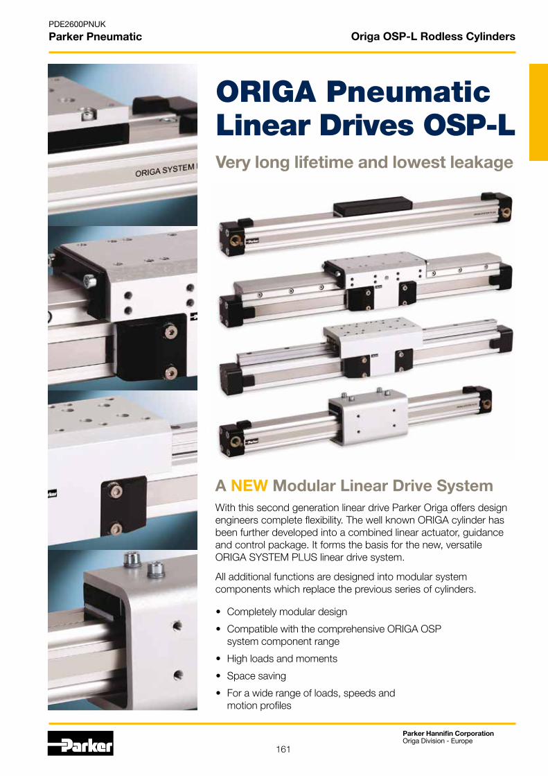
• Completely modular design
• Compatible with the comprehensive ORIGA OSPsystem component range
• High loads and moments
• Space saving
• For a wide range of loads, speeds andmotion profiles
ORIGA PneumaticLinear Drives OSP-L Very long lifetime and lowest leakage
With this second generation linear drive Parker Origa offers design engineers complete flexibility. The well known ORIGA cylinder has been further developed into a combined linear actuator, guidance and control package. It forms the basis for the new, versatile ORIGA SYSTEM PLUS linear drive system.
All additional functions are designed into modular system components which replace the previous series of cylinders.
A NEW Modular Linear Drive System
162
PDE2600PNUK
Parker Pneumatic
Parker Hannifin CorporationOriga Division - Europe
Origa OSP-L Rodless Cylinders
Duplex Connection• Series OSP-L
Multiplex Connection• Series OSP-L
Linear Guides – SLIDELINE• Series OSP-L
Linear Guides– STARLINE
• Series OSP-L
Magnetic Switches• Series OSP-L
Variable Stop VS• Series OSP-L with Linear Guide STL
Basic Linear Drive Standard Version • Series OSP-L
Air Connection on the End-face or both at One End • Series OSP-L
Integrated 3/2 Way Valves• Series OSP-L
Clevis Mounting• Series OSP-L
End Cap Mounting• Series OSP-L
Mid-Section Support• Series OSP-L
Inversion Mounting• Series OSP-L
Introduction – OSP Concept
163
PDE2600PNUK
Parker Pneumatic
Parker Hannifin CorporationOriga Division - Europe
Origa OSP-L Rodless Cylinders
END-FACE AIR CONNECTION
To solve special installation problems.
BOTH AIR CONNECTIONSAT ONE END
For simplified tubing connections and space saving.
INTEGRATED VOE VALVES
The complete compact solution for optimal cylinder control.
DUPLEX CONNECTION
The duplex connection combines two OSP-L cylinders of the same size into a compact unit with high performance.
MULTIPLEX CONNECTION
The multiplex connection combines two or more OSP-L cylinders of the same size into one unit.The orientation of the carriers can be freely selected.
STANDARDVERSIONSOSP-L25 to L63
Standard carrier with integral guidance. End cap can be rotated 4 x 90° to position air connection on any side. Magnetic piston as standard. Dovetail profile for mounting of accessories and the cylinder itself.
BASIC CYLINDER OPTIONS
The special design of the linear drive enables all emissions to be led away.
STAINLESS VERSION
For use in constantly dampor wet environments. Allscrews are A2 quality stainless steel (material no.1.4301 / 1.4303)
ACCESSORIESMAGNETIC SWITCHES TYPE RS, ES, RST, EST
For electrical sensing of end and intermediate piston positions.
MOUNTINGS FOR OSP-L25 TO L63CLEVIS MOUNTING
Carrier with tolerance and parallelism compensation for driving loads supported by external linear guides.
END CAP MOUNTING
For end-mounting of the cylinder.
MID-SECTION SUPPORT
For supporting long cylinders or mounting the cylinder by its dovetail rails.
INVERSION MOUNTING
The inversion mounting transfers the driving force to the opposite side, e. g. for dirty environments.
Options and Accessoriesfor system versatility
Series OSP-L
164
PDE2600PNUK
Parker Pneumatic
Parker Hannifin CorporationOriga Division - Europe
Stainless steelscrews optional.
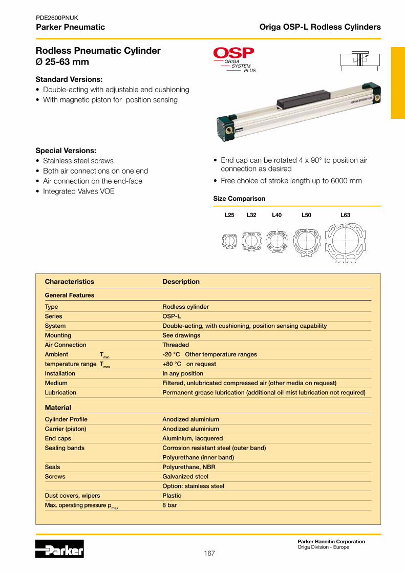
End cap can be rotated to any one of the four positions (before or after delivery) so that the air connection can be in any desired position.
Combined clamping for inner and outer sealing band with dust cover.
Corrosion resistant steel outer sealing band and robust wiper system on the carrier for use in aggressive environments.
Inner sealing band made of polyurethane for best sealing features and extreme slight friction.
Magnetic piston as standard - for contactless position sensing on three sides of the cylinder.
Optimized cylinder profile for maximum stiffness and minimum weight. Integral air passages enable both air connections to be positioned at one end, if desired.
Low friction piston seals for optimized running characteristics
The newly developed product line OSP-L can be simply and neatly integrated into any machine layout.
MOUNTING RAILS ON 3 SIDES
Mounting rails on 3 sides of the cylinder enable modular components such as linear guides, brakes, valves, magnetic switches etc. to be fitted to the cylinder itself. This solves many installation problems, especially where space is limited.
The modular system concept forms an ideal basis for additional customer-specific functions.
Origa OSP-L Rodless Cylinders
Origa System Plus- Innovation from a proven design
165
PDE2600PNUK
Parker Pneumatic
Parker Hannifin CorporationOriga Division - Europe
SLIDELINECost-effective plain bearing guide for medium loads.
Adjustable end cushioning at both ends are standard.
New low profilepiston/carrier design.
Integral dovetail rails on three sides provide many adaptation possibilities (linear guides, magnetic switches, etc.)
Modular system components are simply clamped on.
STARLINERecirculating ball bearing guide for very high loads and precision.
INTEGRATEDVOE VALVESThe complete compact solution for optimal cylinder control.
VARIABLE STOPVSThe variable stop provides simple stroke limitation.
Origa OSP-L Rodless Cylinders
166
PDE2600PNUK
Parker Pneumatic
Parker Hannifin CorporationOriga Division - Europe
Origa OSP-L Rodless Cylinders
For further information and assembly instructions, please contact your local Parker Origa dealer.
The high load capacity of the piston can cope with high bending moments without additional guides.
ORIGA SYSTEM PLUS – rodless linear drives offer maximum flexibility for any application.
The mechanical design of the OSP-L allows synchronised movement of two cylinders.
Optimal system performance by combining multi-axis cylinder combinations.
Integrated guides offer optimal guidance for applications requiring high performance, easy assembly and maintenance freeoperation.
When using external guides, the clevis mounting is used to compensate for deviations in parallelism.
SLIDELINE
STARLINE
OSP-L Application examples
167
PDE2600PNUK
Parker Pneumatic
Parker Hannifin CorporationOriga Division - Europe
Origa OSP-L Rodless Cylinders
Rodless Pneumatic Cylinder Ø 25-63 mm
Standard Versions:• Double-acting with adjustable end cushioning • With magnetic piston for position sensing
Special Versions:• Stainless steel screws• Both air connections on one end • Air connection on the end-face • Integrated Valves VOE
• End cap can be rotated 4 x 90° to position air connection as desired
• Free choice of stroke length up to 6000 mm
Size Comparison
L25 L32 L40 L50 L63
Characteristics Description
General Features
Type Rodless cylinder
Series OSP-L
System Double-acting, with cushioning, position sensing capability
Mounting See drawings
Air Connection Threaded
Ambient Tmin -20 °C Other temperature ranges
temperature range Tmax +80 °C on request
Installation In any position
Medium Filtered, unlubricated compressed air (other media on request)
Lubrication Permanent grease lubrication (additional oil mist lubrication not required)
Material
Cylinder Profile Anodized aluminium
Carrier (piston) Anodized aluminium
End caps Aluminium, lacquered
Sealing bands Corrosion resistant steel (outer band)
Polyurethane (inner band)
Seals Polyurethane, NBR
Screws Galvanized steel
Option: stainless steel
Dust covers, wipers Plastic
Max. operating pressure pmax 8 bar
168
PDE2600PNUK
Parker Pneumatic
Parker Hannifin CorporationOriga Division - Europe
Origa OSP-L Rodless Cylinders
Weight (mass) [kg]
Cylinder series Weight (Mass) [kg] (Basic cylinder) At 0 mm stroke per 100 mm stroke
OSP-L25 0.65 0.197
OSP-L32 1.44 0.354
OSP-L40 1.95 0.415
OSP-L50 3.53
OSP-L63
Cylinder- Theoretical effektive max. Moments max. Load CushionSeries Ø Action Force Action Force FA Mx My Mz F Length[mm] at 6 bar [N] at 6 bar [N] [Nm] [Nm] [Nm] [N] [mm]
OSP-L25 295 250 1.5 15 3 300 17OSP-L32 483 420 3 30 5 450 20OSP-L40 754 640 6 60 8 750 27OSP-L50 1178 1000 10 115 15 1200 30OSP-L63
Loads, Forces and Moments
Choice of cylinder is decided by:
• Permissible loads, forces and moments
• Performance of the pneumatic end cushions.
The main factors here are the mass tobe cushioned and the piston speed atstart of cushioning (unless external cushioning is used, e. g. hydraulic shock absorbers).
The adjacent table shows the maximum values for light, shock-free operation, which must not be exceeded even in dynamicoperation. Load and moment data arebased on speeds v ≤ 0.5 m/s.
When working out the action forcerequired, it is essential to take intoaccount the friction forces generatedby the specific application or load.
Cushioning Diagram
M = F ·l Bending moments are calculated from the centre of the linear actuator
* For cylinders with linear guides or brakes, please be sure to take the mass of the carriage or the brake housing into account.
Max
. per
mis
sib
le p
isto
n sp
eed
at
sta
rt o
f cu
shio
ning
Mass to be cushioned *
Work out your expected moving mass and read off the maximum permissible speed at start of cushioning. Alternatively, take your desired speed and expected mass and find the cylinder size required.Please note that piston speed at start of cushioning is typically ca. 50 % higher than the average speed, and that it is this higher speed which determines the choice of cylinder.
in progress
in progress
0.50.40.30.2
0.10.5 10.30.20.1 2 3 5 10 20 30 50 100 300 5001000 kg
1
23
54
D25D40
D32
D50D63
If the permitted values are exceeded, either additional shock absorbers should be fitted in the area of the centre of the gravity or you can consult us about our special cushioning system- we shall be happy to advise you on your specific application.
For further technical information see catalogue P-A4P012GB
[m/s]
[kg]
169
PDE2600PNUK
Parker Pneumatic
Parker Hannifin CorporationOriga Division - Europe
Origa OSP-L Rodless Cylinders
Features:
• Complete compact solution• Various connection possibilities: Free choice of air connection with rotating end caps with VOE valves, Air connection can be rotated 4 x 90°• Solenoid can be rotated 4 x 90°, • Pilot valve can be rotated 180°• High piston velocities can be achieved with max. 3 exhaust ports• Minimal installation requirements
Integrated 3/2 Way ValvesVOESeries OSP-L25, L32, L40 and L50
For optimal control of the OSP-L cylinder, 3/2 way valves integrated into the cylinder‘s end caps can be used as a compact and complete solution.They allow for easy positioning of the cylinder, smooth operation at the lowest speeds and fast response, making them ideally suited for the direct control of production and automation processes.
Characteristics 3/2 Way Valves VOE
Characteristics 3/2 Way Valves with spring return
Pneumatic diagram
Type VOE-25 VOE-32 VOE-40 VOE-50
Actuation electrical
Basic position P → A open, R closed
Type Poppet valve, non overlapping
Mounting integrated in end cap
Installation in any position
Port size G 1/8 G 1/4 G 3/8 G 3/8
Temperature -10°C to +50°C *
Operating pressure 2-8 bar
Nominal voltage 24 V DC / 230 V AC, 50 Hz
Power consumption 2.5 W / 6 VA
Duty cycle 100%
Electrical Protection IP 65 DIN 40050
* other temperature ranges on request
• Requires just one air connection per valve• Optimal control of the OSP-L cylinder• Excellent positioning characteristics• Integrated operation indicator• Integrated exhaust throttle valve • Manual override - indexed • Adjustable end cushioning • Easily retrofitted – please note the increase in the overall length of the cylinder!
�����
���� �����
�����
���� �����
For further technical information see catalogue P-A4P012GB
170
PDE2600PNUK
Parker Pneumatic
Parker Hannifin CorporationOriga Division - Europe
Origa OSP-L Rodless Cylinders
1-4 5+6 7 8 9 10 11 12-16 17 18 19 20 21 22 23 24 25
OSPL 25 0 0 0 0 0 01100 0 0 0 0 0 0 0 0 0
270° same
side as outerband
270° same
side as outerband
0° in front
0° in front
180° at the back
180° at the back
90° underneath
90° underneath
end-face
end-face
End cap position (air connection)
Cylinder L
(left end side)
Cylinder R
(right end side)
Order Instructions- Basic Cylinder
Air Connection
0 standard
1 end face
2both at one end
3 left standard right end face
4 right standard left end face
A 3/2 Way valve VOE 24 V = Ø 25,32,40,50
B 3/2 Way valve VOE 230 V~ / 110 V= Ø 25,32,40,50
C 3/2 Way valve VOE 48 V = Ø 25,32,40,50
E 3/2 Way valve VOE 110 V~ Ø 25,32,40,50
End cap position
0 l+r 0° = in front
1 l+r 90° = under-neath
2 l+r 180° = at the back
3 l+r 270° = same side as outerband
4 l 90° = underneath; r 0° = in front
5 l 180° = at the back; r 0° = in front
6 l 270° = same side as outerband; r 0° = in front
7 l 0° = in front; r 90° = underneath
8 l 180° = at the back; r 90° = underneath
9 l 270° = same side as outerband; r 90° = underneath
A l 0° = in front; r 180° = at the back
B l 90° = underneath; r 180° = at the back
C l 270° = same side as outerband; r 180° = at the back
D l 0° = in front; r 270° = same side as outerband
E l 90° = underneath; r 270° = same side as outerband
F l 180° = at the back; r 270° = same side as outerband
Version / Piston
0 standard
1 Tandem
Seals
0 standard
Lubrication
0 standard
add. Guide Carriage0 without
Screws
0 standard
1 Stainless
Cushioning
0 standard
1 max. length
Piston Mounting0 without
1clevis mounting
Guides/ Brakes/ Inversion0 without
MInversion
Ø 16-80
NDuplex
Ø 25,32,40,50
Cover / Cable Channel0 standard
1 Cable channel
2Cable channel two-sided
Measuring system0 without
Stroke
in mm (5 digits)
Piston-Ø
25
32
40
in progress
in progress
171
PDE2600PNUK
Parker Pneumatic
Parker Hannifin CorporationOriga Division - Europe
Origa OSP-L Rodless Cylinders
plastic wiper
oiled felt wiper
aluminium guide carriage
aluminium guide rail
slide adjustment elements
pressure plate and adjustment screws
grease nipple
Features:
• Anodised aluminium guide rail with prism-shaped slideway arrangement
• Adjustable plastic slide elements
• Composite sealing system with plastic and felt wiper elements to remove dirt and lubricate the slideways
• Corrosion resistant version available on request
• Any length of stroke up to 5500 mm (longer strokes on request)
Plain Bearing GuideSLIDELINESeries SL 25 to 63 for Linear Drive
Loads, Forces and Moments
* Please note: In the cushioning diagram, add the mass of the guide carriage to the mass to be cushioned.
Technical Data
The table shows the maximum permis sible values for smooth operation, which should not be exceeded even under dynamic conditions.
The load and moment figures apply to speeds v < 0.2 m/s.
1) Corrosion resistant fixtures available on request
Series SL
For linear drive
Max. moments [Nm] Max. loads [N] Mass of linear drive with guide [kg] Mass * of guide carriage[kg]
Order No. ** SLIDELINE 1)
Guide without cylinder
Mx My Mz Fy,Fz with 0 mm stroke
increase per 100 mm stroke
SL25 OSP-L25 14 34 34 675 1.55 0.39 0.61 20342FIL
SL32 OSP-L32 29 60 60 925 2.98 0.65 0.95 20196FIL
SL40 OSP-L40 50 110 110 1600 4.05 0.78 1.22 20343FIL
SL50 OSP-L50 77 180 180 2000 6.72 0.97 2.06
SL63 OSP-L63 120 260 260 2500 11.66 1.47 3.32
** Please use this order pattern: Order-No. + ”stroke in mm” (5 digits)Example: SLIDELINE guide D25mm, stroke 1000mm: 20342-01000
For further technical information see catalogue P-A4P012GB
in progress
172
PDE2600PNUK
Parker Pneumatic
Parker Hannifin CorporationOriga Division - Europe
Origa OSP-L Rodless Cylinders
1-4 5+6 7 8 9 10 11 12-16 17 18 19 20 21 22 23 24 25
OSPL 25 0 0 0 0 0 01100 0 0 0 0 0 0 0 0 0
Order Instructions SLIDELINE
270° same
side as outerband
270° same
side as outerband
0° in front
0° in front
180° at the back
180° at the back
90° underneath
90° underneath
end-face
end-face
End cap position (air connection)
Cylinder L
(left end side)
Cylinder R
(right end side)
Air Connection
0 standard
1 end face
2 both at one end
3 left standard right end face
4 right standard left end face
A 3/2 Way valve VOE 24 V = Ø 25,32,40,50
B 3/2 Way valve VOE 230 V~ / 110 V= Ø 25,32,40,50
C 3/2 Way valve VOE 48 V = Ø 25,32,40,50
E 3/2 Way valve VOE 110 V~ Ø 25,32,40,50
End cap position
0 l+r 0° = in front
1 l+r 90° = under-neath
2 l+r 180° = at the back
3 l+r 270° = same side as outerband
4 l 90° = underneath; r 0° = in front
5 l 180° = at the back; r 0° = in front
6 l 270° = same side as outerband; r 0° = in front
7 l 0° = in front; r 90° = underneath
8 l 180° = at the back; r 90° = underneath
9 l 270° = same side as outerband; r 90° = underneath
A l 0° = in front; r 180° = at the back
B l 90° = underneath; r 180° = at the back
C l 270° = same side as outerband; r 180° = at the back
D l 0° = in front; r 270° = same side as outerband
E l 90° = underneath; r 270° = same side as outerband
F l 180° = at the back; r 270° = same side as outerband
Version / Piston
0 standard
1 Tandem
Seals
0 standard
Lubrication
0 standard
add. Guide Carriage0 without
2 Guide Carriage Slideline SL
Ø 25-63
Screws
0 standard
1 Stainless
Cushioning
0 standard
Piston Mounting0 without
Guides/ Brakes/ Inversion0 without
2Slideline SL
Ø 25-63
Measuring system0 without
Stroke
in mm (5 digits)
Piston-Ø
25
32
40
in progress
in progress
Cover / Cable Channel0 standard
1 Cable channel
2Cable channel
two-sided
173
PDE2600PNUK
Parker Pneumatic
Parker Hannifin CorporationOriga Division - Europe
Origa OSP-L Rodless Cylinders
grease nipple
integratedwiper
aluminium carriage
polished, hardened steel guide rail
guide carriage
The sum of the loads should not exceed >1.
≤ 1Mz
Mz max
Fz
Fzmax
Mx
Mxmax
My
My max
Fy
Fymax
+ + + +
Features:
• Polished and hardened steel guide rail
• For very high loads in all directions
• High precision
• Integrated wiper system
• Integrated grease nipples
• Any length of stroke up to 3700 mm
• Anodized aluminium guide carriage – dimensions compatible with OSP guides SLIDELINE
• Installation height (STL25 - 32) compatible with OSP-L guides SLIDELINE
Recirculating Ball Bearing GuideSTARLINESeries STL 16 to 50 for Linear Drive
Loads, Forces and Moments
* Please note: The mass of the carriage has to be added to the total moving mass when using the cushioning diagram
Technical Data
The table shows the maximal permissible loads. If multiple moments and forces act upon the cylinder simultaneously, the following equation applies:
The table shows the maximum permissible values for light, shock-free operation, which must not be exceeded even under dynamic conditions.
• Maximum speed
STL25 to 50: v = 5 m/s
SeriesSTL
For linear drive
Max. moments [Nm] Max. loads [N] Mass of linear drive with guide [kg] Mass * of guidecarriage[kg]
Order No. **STARLINE
Guide without cylinderMx My Mz Fy Fz with
0 mm strokeincrease per 100 mm stroke
STL25 OSP-L25 50 110 110 3100 3100 1.733 0.369 0.835 21112
STL32 OSP-L32 62 160 160 3100 3100 2.934 0.526 1.181 21113
STL40 OSP-L40 150 400 400 4000 7500 4.452 0.701 1.901 21114
STL50 OSP-L50 210 580 580 4000 7500 7.361 0.936 2.880in progress
** Please use this order pattern: Order-No. + ”stroke in mm” (5 digits)Example: STARLINE guide D25mm, stroke 1000mm: 21112-01000
For further technical information see catalogue P-A4P012GB
174
PDE2600PNUK
Parker Pneumatic
Parker Hannifin CorporationOriga Division - Europe
Loading 1 Top carrier
Loading 2Side carrier
Origa OSP-L Rodless Cylinders
Mid-section supports are required from a certain stroke length to prevent excessive deflection and vibration of the linear drive. The diagrams show the maximum permissible unsupported length in relation to loading. A distinction must be drawn between loading 1 and loading 2. Deflection of 0.5 mm max. between supports is permissible.
Mid-Section Support
Permissible Unsupported Length STL25 to STL50
Note:For speeds v > 0.5 m/s the distance between supports should not exceed 1 m.
Permissible Unsupported Length STL25 to STL50
Loading 2 – Side carrier
Load
F
Distance between supports
1= OSP-L STL 25 2= OSP-L STL 32 3= OSP-L STL 40 4= OSP-L STL 50
1 = OSP-L STL 252 = OSP-L STL 323 = OSP-L STL 404 = OSP-L STL 50
43
21
Load
F
Distance between supports
Loading 1 – Top carrier
1 = OSP-L STL 25 2 = OSP-L STL 32 3 = OSP-L STL 40 4 = OSP-L STL 50
1 = OSP-L STL 252 = OSP-L STL 323 = OSP-L STL 404 = OSP-L STL 50
432
1
175
PDE2600PNUK
Parker Pneumatic
Parker Hannifin CorporationOriga Division - Europe
Origa OSP-L Rodless Cylinders
Shock Absorber Selection in Dependence on Mass and Speed for Series OSP-L-STL25
The values relate to an effective driving force of 250 N (6 bar)
Variable StopType VS25 to VS50
Stop
Shock absorber holder with shock absorber
Shock absorber with plastic cap
Arrangement with two variable stops
The variable stop Type VS provides simple stroke limitation.It can be retrofitted and positioned anywhere along the stroke length.
For every cylinder diameter two types of shock absorber are available – see „Shock Absorber Selection“ below.
Mid-section supports and magnetic switches can still be fitted on the same side as the variable stop.
Depending on the application, two variable stops can be fitted if required.
Shock Absorber Selection
The shock absorber is selected in dependence on the mass and speed.
The mass of the carrier itself must be taken into account.
Sp
eed
[m/s
]
Mass [kg]
Type SA12S2N
Type SA12S
Sp
eed
[m/s
]
Mass [kg]
Type SA14
Type SA14S
Sp
eed
[m/s
]
Mass [kg]
Type SA20
Type SA20S
Sp
eed
[m/s
]
Mass [kg]
Type SAI25
Type SAI25S
Shock Absorber Selection in Dependence on Mass and Speed for Series OSP-L-STL32
The values relate to an effective driving force of 420 N (6 bar)
Shock Absorber Selection in Dependence on Mass and Speed for Series OSP-L-STL40
The values relate to an effective driving force of 640 N (6 bar)
Shock Absorber Selection in Dependence on Mass and Speed for Series OSP-L-STL50
The values relate to an effective driving force of 1000 N (6 bar)
176
PDE2600PNUK
Parker Pneumatic
Parker Hannifin CorporationOriga Division - Europe
Item 1Stop complete with fittingsItem 2
Shock absorber holder complete with fittings – without shock absorber
Item 3Shock absorber with plastic cap
Origa OSP-L Rodless Cylinders
Variable StopType VS25 to VS50
Item Description Size
VS25 VS32 VS40 VS50
Type Order-No. Type Order-No. Type Order-No. Type Order-No.
1 Stop, complete – 21197FIL – 21198FIL – 21199FIL
in progress2 Shock absorber
holder complete– 21202FIL – 21203FIL – 21204FIL
3 *Shock absorber, soft SA12S2N 7723FIL SA14 7708FIL SA20 7710FIL
Shock absorber, hard SA12S 7707FIL SA14S 7709FIL SA20S 7711FIL
* Shock absorber with plastic cap
Order Instructions – Variable Stop Type VS25 to VS50 without cylinder and without guide
Note: Order instructions for VS in combination with the Starline see page 177 pos.18
For further technical information see catalogue P-A4P012GB
177
PDE2600PNUK
Parker Pneumatic
Parker Hannifin CorporationOriga Division - Europe
Origa OSP-L Rodless Cylinders
1-4 5+6 7 8 9 10 11 12-16 17 18 19 20 21 22 23 24 25
OSPL 25 0 0 0 0 0 01100 0 0 0 0 0 0 0 0 0
Order Instructions - STARLINE
270° same
side as outerband
270° same
side as outerband
0° in front
0° in front
180° at the back
180° at the back
90° underneath
90° underneath
end-face
end-face
End cap position (air connection)
Cylinder L
(left end side)
Cylinder R
(right end side)
End cap position
0 l+r 0° = in front
1 l+r 90° = underneath
2 l+r 180° = at the back
3 l+r 270° = same side as outerband
4 l 90° = underneath; r 0° = in front
5 l 180° = at the back; r 0° = in front
6 l 270° = same side as outerband; r 0° = in front
7 l 0° = in front; r 90° = underneath
8 l 180° = at the back; r 90° = underneath
9 l 270° = same side as outerband; r 90° = underneath
A l 0° = in front; r 180° = at the back
B l 90° = underneath; r 180° = at the back
C l 270° = same side as outerband; r 180° = at the back
D l 0° = in front; r 270° = same side as outerband
E l 90° = underneath; r 270° = same side as outerband
F l 180° = at the back; r 270° = same side as outerband
Version / Piston
0 standard
1 Tandem
Seals
0 standard
Lubrication
0 standard
add. Guide Carriage0 without
B Guide Carriage Starline STL
Screws
0 standard
Cushioning0 standard
1 max. length
2variable stop complete
VS soft left for Starline
3variable stop complete
VS hard left for Starline,
4variable stop complete
VS soft right for Starline
5variable stop complete
VS hard right for Starline
6
variable stop complete
VS soft both sides for Starline
7
variable stop complete
VS hard both sides for Starline
Piston Mounting0 without
Guides/ Brakes/ Inversion0 without
B Starline STL
Measuring system0 without
Stroke
in mm (5 digits)
Piston-Ø
25
32
40
in progress
Air Connection
0 standard
1 end face
2both at one end
3 left standard right end face
4 right standard left end face
A 3/2 Way valve VOE 24 V = Ø 25,32,40,50
B 3/2 Way valve VOE 230 V~ / 110 V= Ø 25,32,40,50
C 3/2 Way valve VOE 48 V = Ø 25,32,40,50
E 3/2 Way valve VOE 110 V~ Ø 25,32,40,50
Cover / Cable Channel0 standard
1 Cable channel
2Cable channel two-sided