16
Remote Power Panel Operation instructions Original Manual 2CCC444013M0201 Rev. 1.0, Date of Release: 02/2016
| Date post: | 17-Jun-2019 |
| Category: |
Documents |
| Upload: | truongxuyen |
| View: | 213 times |
| Download: | 0 times |

Remote Power PanelOperation instructions
Original Manual 2CCC444013M0201 Rev. 1.0, Date of Release: 02/2016

2 | Remote Power Panel – Operation instructions
Table of contents
Unpacking and checking the cabinet
Visual control of the packaging 3 Unpacking the cabinet 3 Transportation of the cabinet 4 Opening the cabinet 5 Checking door hinge 5 Checking proper function and screws 6Checking touch proof security IP20B 6
Cabinet mountingBottom fastening 7
Load connectionsInstallation of SMISSLINE TP devices 8Wiring of SMISSLINE TP devices 8
Line connection of „XT4N 250A“Removing protection housing 9Opening of „Power Cage Clamp” 9Connecting main power supply 10Mounting of protection housing 11Closing of the „Power Cage Clamp” terminals 11
OperationEkip Display for “XT4 250A” 12Mounting of plug-in SMISSLINE TP devices 12Load connection of SMISSLINE TP devices 12Disconnection of a device 12Position plug-in connector 12
Maintenance 12
Approved SMISSLINE TP devicesMCB 1pole 13MCB 2pole (with protected neutral) 13Signal contact collective alarm 13
Technical DataRPP-250A-X3-X4-X5-X6-X7-X8 14RPP-500A-X3-X4-X5-X6-X7-X8 14RPP-750A-X3-X4-X5-X6-X7-X8 15 RPP-1000A-X3-X4-X5-X6-X7-X8 15
Pictures in this manual are given for the Remote Power Panel 500A according to the following type code: RPP-500A-P-INT-RTI-BCM-PQL-TLAll other cabinets (250A, 750A, 1000A) can be derived from this manual.
For installation/assembly, please refer to the “Assembly inst-ruction manual”. (2CCR123456R7890)

Remote Power Panel – Operation instructions | 3
Unpacking and checking the cabinet
Visual control of the packaging– Check the packaging carefully for damage
Unpacking the cabinet– Do not use a knife to cut the package sealing.
– After unpacking, the cabinet should look as shown in Fig.1
– The size of the cabinet canvary, depending to your order – RPP-250A-X3-X4-X5-X6-X7-X8 (Fig.1.1) – RPP-500A-X3-X4-X5-X6-X7-X8 (Fig.1.1) – RPP-750A-X3-X4-X5-X6-X7-X8 (Fig.1.2) – RPP-1000A-X3-X4-X5-X6-X7-X8 (Fig.1.3)
– Attention! The cabinet is top-heavy!
Fig.1: Unpacked cabinet
Fig.1.1: Cabinet small – 250/500A | Fig.1.2: Cabinet medium – 750 A | Fig.1.3: Cabinet large – 1000 A
1 2 3
4 | Remote Power Panel – Operation instructions
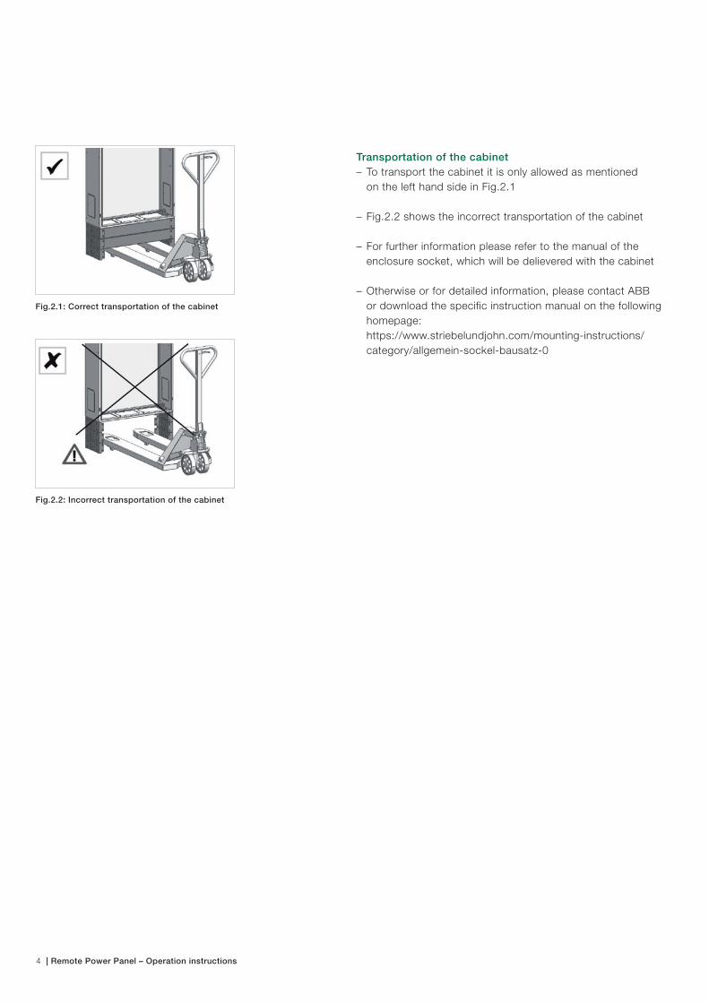
Fig.2.2: Incorrect transportation of the cabinet
Fig.2.1: Correct transportation of the cabinet
Transportation of the cabinet– To transport the cabinet it is only allowed as mentioned on the left hand side in Fig.2.1
– Fig.2.2 shows the incorrect transportation of the cabinet
– For further information please refer to the manual of the enclosure socket, which will be delievered with the cabinet
– Otherwise or for detailed information, please contact ABB or download the specific instruction manual on the following homepage: https://www.striebelundjohn.com/mounting-instructions/ category/allgemein-sockel-bausatz-0

Remote Power Panel – Operation instructions | 5
Fig.3: cabinet key
Fig.3.1:Correct positiont
Fig.3.2: Forbidden position
Opening cabinet– Only authorized/skilled persons people are allowed to open the cabinet
– To open the electrical cabinet it is necessary to use a common cabinet key, displayed in Fig.3
– Each door can be open to an maximum angle of 180°
Checking door hinge– Check that all bolts from the door hinge are positioned as shwon in Fig.3.1
– Fig.3.2 shows the forbidden position
– The bolts are an addiontal protection if the earthing cable e.g. are damaged

6 | Remote Power Panel – Operation instructions
Fig.4: Overview of all screws which shall be checked after transportaion
Checking proper function and screws– Check all screws and nuts in the cabinet after transportation. (Fig.4)
– Retighten all screws and nuts in the cabinet after transpor- tation, if necessary. (Fig.4)
– Especially pay attention to the screws which are in contact with conductive parts 1. All screws for each “XT4N 250A” 2. All screws for the earthing terminal (8 Nm) 3. All screws for the earthing of the cabinet (8 Nm) 4. All screws at the incoming terminal blocks – ZLS224 5. All screws for the earthing of the door (8 Nm) 6. All screws at the devices on the DIN rail 6.1. CMS600/CMS700 6.2. AC500-eco 6.3. 4-pole RCCB/MCB 7. All screws of additional controlling devices which are mounted on the DIN rail 8. All screws of the controlling devices in the front door of the panel
For further Details of the each tightening torque please check the technical specification of each device.
In case of use of terminal blocks for copper conductors, there is no need to check these terminals, due to the innovative “Power cage clamp” technology, provided from WAGO
– All other parts shall be checked
Checking touch proof security IP20B– Ensure that all required items are in the correct position in the cabinet, especially the parts which are responsible for touch proof security
– Parts that shall be in place are – Terminal covers of all ZLS224 – Terminal covers of all XT4 – Protection covers of all unused terminals “Power cage clamp”
– Ensure that the minium cross section of all power cables feeding the SMISSLINE busbar system including neutral are 50 mm²
– Only if these parts are mounted correctly the panel is protected IP20B
– Checking the complete cabinet for touch proof security
– If there is anything not correctly installed, it is not allowed to go further with the installing

Remote Power Panel – Operation instructions | 7
Fig.5: Floor fastener for plinth
Bottom fastening– Up to three sockets may be delivered with the cabinet
– At least one socket shall mounted below the cabinet – Needed for fixation of the cable – Needed for fixation of the cabinet to the ground/floor
– The maximum amount of sockets, mounted simultaneously are three
– To mount the electrical cabinet to the floor, use all four “Floor fastener for plinth” brackets which are delivered with the cabinet (Fig.5)
– For mounting instruction please refer to manual “RZ3P4“ provided from Striebel&John
– For safety reason it is forbidden to install the cabinet without the “Floor fastener for plinth”
– The maximum weight of the cabinet including SMISSLINE is mentioned in the technical data
Cabinet mounting

8 | Remote Power Panel – Operation instructions
Load connections
For detailed information please contact ABB or download the specific instruction manual for SMISSLINE TP on the ABB homepage: http://new.abb.com/low-voltage/products/system-pro-m/smissline-tp
Installation of SMISSLINE TP devices– Ensure that each powerbus does not exceed 250A rated current,referring to the consumption of the servers – Note: For Datacenter applications it might be preferable to feed each MCCB with maximum 125A due to redun- dancy in case of a breakdown/failure of the other MCCB
– Load connection of SMISSLINE TP devices.
– To ensure that the devices are correctly connected, please check the position of the fixing clip of each MCB
– The position shall be in the upper position as in Fig.7
Wiring of SMISSLINE TP devices– Wiring of each SMISSLINE TP device depends on the local regulations and standards
– Only authorized personnel are allowed to wire electrical devices/parts inside the cabinet
– Tightening torque for the screws are 2.8 Nm
For detailed information please contact ABB or download the specific technical instructions manual on the ABB homepage:https://library.e.abb.com/public/3fe78b04ddd7fc08c1257c1 c0027f812/2CCC451059C0202.pdf– Document Number: 2CCC451059C0202
Fig.6: Assembly of an SMISSLINE device
Fig.7: Plug-in position
Remote Power Panel – Operation instructions | 9
Line connection of „XT4N 250A“
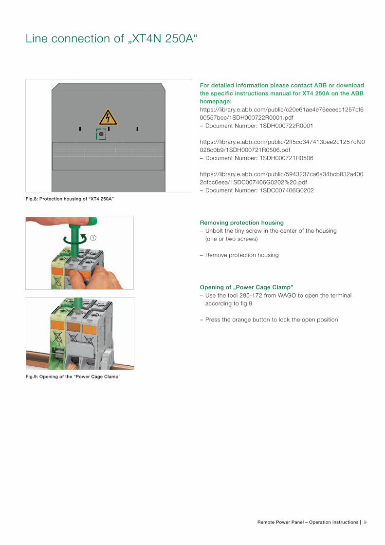
For detailed information please contact ABB or download the specific instructions manual for XT4 250A on the ABB homepage:https://library.e.abb.com/public/c20e61ae4e76eeeec1257cf600557bee/1SDH000722R0001.pdf– Document Number: 1SDH000722R0001
https://library.e.abb.com/public/2ff5cd347413bee2c1257cf90028c0b9/1SDH000721R0506.pdf– Document Number: 1SDH000721R0506
https://library.e.abb.com/public/5943237ca6a34bcb832a4002dfcc6eea/1SDC007406G0202%20.pdf– Document Number: 1SDC007406G0202
Removing protection housing– Unbolt the tiny screw in the center of the housing (one or two screws)
– Remove protection housing
Opening of „Power Cage Clamp”– Use the tool 285-172 from WAGO to open the terminal according to fig.9
– Press the orange button to lock the open position
Fig.8: Protection housing of “XT4 250A”
Fig.9: Opening of the “Power Cage Clamp”

10 | Remote Power Panel – Operation instructions
Connecting main power supply– All electrical connections shall always correspond to the national and local standards
– Connect the Cu cable in the same way as they connected on the load side (N L1 L2 L3) – Each cable cross-section shall be according to current load of XT4N 250A or the terminal blocks for copper “POWER Cage Clamp” – N, L1, L2, L3: min.120mm²; Cu – PE: : min. 70mm²; Cu
– Cable shall be according to IEC 60228 Class 5 or Class 6, 105 °C
– For connection to XT4N 250A use cable lugs according to Fig.11 – Cable lugs shall be suitable for Cu 120 mm² and switch- gear connection (or bigger, depending on the cross section of the line/incoming cable) – We recommend “Tubular cable lugs for switchgear connection – “9SG8C1K” from Klauke®
– To comply with the required minimum force according to IEC 61238 T1 we recommend the crimp-type-method “indent crimping” as illustrated in the Fig.10 and 11 – Example: Minimum 7200N when 120mm² is installed
– Use for each phase a heat shrinking tube to isolate the cable lug
– For more connection options , please refer to the Document: 1SDC007406G0202 provided from ABB
– Connect the cable with “XT4 250A”and fix the screws with a torque of 8 Nm as shown in Fig.12
– For connection to the terminal blocks for copper “POWER Cage Clamp” please refer to instruction manuel , provided from Wago – There is no need for cable lugs
– For detailed information please refer to the assembly instruction of the RPP
Fig.10: indent crimping
Fig.11: indent crimping; practical example
Fig.12: Details on connection of XT4
Remote Power Panel – Operation instructions | 11
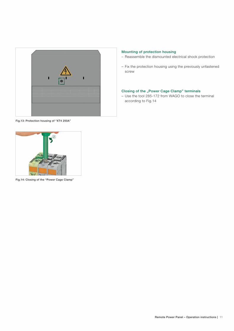
Mounting of protection housing– Reassemble the dismounted electrical shock protection
– Fix the protection housing using the previously unfastened screw
Closing of the „Power Cage Clamp” terminals– Use the tool 285-172 from WAGO to close the terminal according to Fig.14
Fig.13: Protection housing of “XT4 250A”
Fig.14: Closing of the “Power Cage Clamp”

12 | Remote Power Panel – Operation instructions
Operation
Ekip Display for “XT4N 250A”For further information please refer to the user and opera-tor manual. Address of ABB library: https://library.e.abb.com/public/248ef6f757ef2bd6c125799f005ca1dd/1SDH000892R0002.pdf– Document Number: 1SDH000892R0002
Mounting of plug-in SMISSLINE TP devices– Before plug-in the device, it shall be switched off!
– Mount all devices onto the SMISSLINE TP system as pictured in Fig.15
– Ensure that each powerbus does not exceed 250 A – see also technical data – Note: For datacenter applications/crictical power applications it might be preferable to feed each powerbus with maximum 125 A due to redundancy in case of a breakdown/failure of one MCCB
Load connection of SMISSLINE TP devices.– To ensure that the device is correctly connected please check the position of the fixing clip
– The position shall be in the upper position as in Fig.16
Disconnection of a device– Before disconnecting, the device shall be switched off!– To dismount the device open the fixing clip, displayed in Fig.17– Remove or change device
Position plug-in connector– First: Lift contact gate (Fig.18)– Second: Bring plug contacts to required position (L1, L2 or L3) (Fig.18)
Fig.15: Assembly of a SMISSLINE device
Fig.18: Change position of plug contacts
Fig.16: Plug-in position
Fig.17: Disconnecting a device

Remote Power Panel – Operation instructions | 13
Maintenance No maintenance necessary.
Signal contact collective alarm
Rated current Product ID Catalog description
1NO (right side mounting)
2CCS500900R0216 SK40010-R SA
1NO (left side mounting)
2CCS500900R0141 SK40010-L SA
Approved SMISSLINE TP devices
Only the listed devices may be used in combination with the RPP Panel.
MCB 1pole
Rated current Product ID Catalog description
16A 2CCS571001R0164 S401M-C16
16A 2CCS571001R0467 S401M-K16
32A 2CCS571001R0324 S401M-C32
32A 2CCS571001R0537 S401M-K32
MCB 2pole (with protected neutral)
Rated current Product ID Catalog description
16A 2CCS571103R8164 S401M-C16NP
16A 2CCS571103R8467 S401M-K16NP
32A 2CCS571103R8324 S401M-C32NP
32A 2CCS571103R8537 S401M-K32NP
14 | Remote Power Panel – Operation instructions
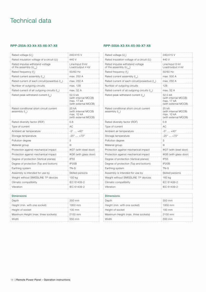
RPP-250A-X3-X4-X5-X6-X7-X8
Rated voltage (Un) 240/415 V
Rated insulation voltage of a circuit (Ui) 440 V
Rated impulse withstand voltage of the assembly (Uimp)
Line/input 8 kVLoad/output 4 kV
Rated frequency (fn) 50/60 Hz
Rated current assembly (InA) max. 250 A
Rated current of each circuit/powerbus (Inc) max. 250 A
Number of outgoing circuits max. 128
Rated current of all outgoing circuits (Inc) max. 32 A
Rated peak withstand current (Ipk) 52.5 kA (with internal MCCB)max. 17 kA (with external MCCB)
Rated conditional short-circuit current assembly (Icc)
25 kA (with internal MCCB)max. 10 kA (with external MCCB)
Rated diversity factor (RDF) 0.8
Type of current AC
Ambient air temperature -5° … +40°
Storage temperature -25° … +70°
Pollution degree 3
Material group III
Protection against mechanical impact IK07 (with steel door)
Protection against mechanical impact IK06 (with glass door)
Degree of protection (Vertical planes) IP55
Degree of protection (Top and bottom) IP20B
Earthing system TN-S
Assembly is intended for use by Skilled persons
Weight without SMISSLINE TP devices 150 kg
Climatic compatibility IEC 61439-2
Vibration IEC 61439-2
Dimensions
Depth 350 mm
Height (min. with one socket) 1950 mm
Height of socket 100 mm
Maximum Height (max. three sockets) 2150 mm
Width 550 mm
RPP-500A-X3-X4-X5-X6-X7-X8
Rated voltage (Un) 240/415 V
Rated insulation voltage of a circuit (Ui) 440 V
Rated impulse withstand voltage of the assembly (Uimp)
Line/input 8 kVLoad/output 4 kV
Rated frequency (fn) 50/60 Hz
Rated current assembly (InA) max. 500 A
Rated current of each circuit/powerbus (Inc) max. 250 A
Number of outgoing circuits 128
Rated current of all outgoing circuits (Inc) max. 32 A
Rated peak withstand current (Ipk) 52.5 kA (with internal MCCB)max. 17 kA (with external MCCB)
Rated conditional short-circuit current assembly (Icc)
25 kA (with internal MCCB)max. 10 kA (with external MCCB)
Rated diversity factor (RDF) 0.8
Type of current AC
Ambient air temperature -5° … +40°
Storage temperature -25° … +70°
Pollution degree 3
Material group III
Protection against mechanical impact IK07 (with steel door)
Protection against mechanical impact IK06 (with glass door)
Degree of protection (Vertical planes) IP55
Degree of protection (Top and bottom) IP20B
Earthing system TN-S
Assembly is intended for use by Skilled persons
Weight without SMISSLINE TP devices 160 kg
Climatic compatibility IEC 61439-2
Vibration IEC 61439-2
Dimensions
Depth 350 mm
Height (min. with one socket) 1950 mm
Height of socket 100 mm
Maximum Height (max. three sockets) 2150 mm
Width 550 mm
Technical data

Remote Power Panel – Operation instructions | 15
RPP-750A-X3-X4-X5-X6-X7-X8
Rated voltage (Un) 240/415 V
Rated insulation voltage of a circuit (Ui) 440 V
Rated impulse withstand voltage of the assembly (Uimp)
Line/input 8 kVLoad/output 4 kV
Rated frequency (fn) 50/60Hz
Rated current assembly (InA) max. 750A
Rated current of each circuit/powerbus (Inc) max. 250A
Number of outgoing circuits max. 192
Rated current of all outgoing circuits (Inc) max. 32 A
Rated peak withstand current (Ipk) 52.5 kA (with internal MCCB)max. 17 kA (with external MCCB)
Rated conditional short-circuit current assembly (Icc)
25 kA (with internal MCCB)max. 10 kA (with external MCCB)
Rated diversity factor (RDF) 0.8
Type of current AC
Ambient air temperature -5° … +40°
Storage temperature -25° … +70°
Pollution degree 3
Material group III
Protection against mechanical impact IK07 (with steel door)
Protection against mechanical impact IK06 (with glass door)
Degree of protection (Vertical planes) IP55
Degree of protection (Top and bottom) IP20B
Earthing system TN-S
Assembly is intended for use by Skilled persons
Weight without SMISSLINE TP devices 175 kg
Climatic compatibility IEC 61439-2
Vibration IEC 61439-2
Dimensions
Depth 350 mm
Height (min. with one socket) 1950 mm
Height of socket 100 mm
Maximum Height (max. three sockets) 2150 mm
Width 800 mm
RPP-1000A-X3-X4-X5-X6-X7-X8
Rated voltage (Un) 240/415 V
Rated insulation voltage of a circuit (Ui) 440 V
Rated impulse withstand voltage of the assembly (Uimp)
Line/input 8 kVLoad/output 4 kV
Rated frequency (fn) 50/60 Hz
Rated current assembly (InA) max. 1000 A
Rated current of each circuit/powerbus (Inc) max. 250 A
Number of outgoing circuits max. 256
Rated current of all outgoing circuits (Inc) max. 32 A
Rated peak withstand current (Ipk) 52.5 kA (with internal MCCB)max. 17 kA (with external MCCB)
Rated conditional short-circuit current assembly (Icc)
25 kA (with internal MCCB)max. 10 kA (with external MCCB)
Rated diversity factor (RDF) 0.8
Type of current AC
Ambient air temperature -5° … +40°
Storage temperature -25° … +70°
Pollution degree 3
Material group III
Protection against mechanical impact IK07 (with steel door)
Protection against mechanical impact IK06 (with glass door)
Degree of protection (Vertical planes) IP55
Degree of protection (Top and bottom) IP20B
Earthing system TN-S
Assembly is intended for use by Skilled persons
Weight without SMISSLINE TP devices 200 kg
Climatic compatibility IEC 61439-2
Vibration IEC 61439-2
Dimensions
Depth 350 mm
Height (min. with one socket) 1950 mm
Height of socket 100 mm
Maximum Height (max. three sockets) 2150 mm
Width 1050 mm

Contact us
ABB Switzerland Ltd.Low Voltage ProductsFulachstrasse 1508201 Schaffhausen, SwitzerlandPhone: +41 58 586 41 11Fax: +41 58 586 42 22Email: [email protected] www.abb.com
For technical questions please refer to:[email protected]
© C
opyr
ight
AB
B 2
CC
C44
4013
M02
01 0
2/16Note:
We reserve the right to undertake technicalchanges as well as changes to the content ofthis document at any time.For purchase orders, agreed conditions apply.ABB does not take responsibility for any mistakesor incompleteness in this document.
ABB reserves all rights to this document and tothe information and topics contained in it. Thisalso applies to any possible claims to copyrightor patents. Forwarding and/or the duplication ofthis document without the express permission ofABB is forbidden.
ABB reserves all rights to this document and tothe information and topics contained in it. Thisalso applies to any possible claims to copyrightor patents. Forwarding and/or the duplication ofthis document without the explicit permission ofABB is forbidden.
This document has been prepared and checkedwith great care. Should it, however, containerrors, the user is asked to report these to ABB.
Copyright© 2016 ABBAll rights reserved


