21
Manufacturers of Fire Detection Equipment www.globalfire.pt Version 0.9 - 11/2011 ORION EX Fire Detection and Extinguishing Control Panel INSTALLATION, OPERATION AND MAINTENANCE MANUAL

Manufacturers of Fire Detection Equipment
www.globalfire.pt
INSTALLATION, OPERATION AND MAINTENANCE MANUAL - V0.9 - 10/2011
ORION EX-L - Conventional Fire Detection & Extinguishing Panel
Version 0.9 - 11/2011
ORION EXFire Detection and Extinguishing Control Panel
INSTALLATION, OPERATION AND MAINTENANCE MANUAL

Key Features
3 Fire Detection Zones. Up to 32 conventional smoke and/or heat detectors per Zone Active End of Line monitoring Programmable Pre-Release and Extinguishing times Remote Manual Activation and Remote Abort Input Electrovalve and Pressure Switch Status Indication One man test Supervised auxiliary 24 volt supply output 2 Supervised/ monitored sounder circuits 2 Remote inputs used for activation of Evacuation and Reset 2 Relay outputs fire and fault with status indication Fully EN 54-2, EN54-4 and EN 12094-1 compliant
ORION EX-L
The ORION EX-L Conventional Fire Detection and Extinguishing Panel offers a creatively designed and aesthetically pleasing solution to satisfy the growing world demand for dependable Fire Suppression Systems.
The ORION EX-L is designed and manufactured to comply with EN 54-2, EN 54-4 and EN 12094-1. The outstanding programmable features included in this panel are best suited to be installed in expensive housing areas and in general in all areas where loss of equipment can partially or totally disrupt the proper functioning of a business.
Operation is extremely intuitive, offering simple control and one-button disablement facilities, as well as the one man test mode which provides simple and efficient testing of the system. range.
Advanced configuration solutions include the following: programmable pre-release and extinguishing times, electrovalve and flow switch status indications, manual and abort remote activation. There are 3 normal fire detection zones. All inputs are fully monitored for both Fire, Activation and Fault Conditions.
Plans are under way to further complement this new range of extinguishing devices. Devices such as repeater panels, addressable system interfaces, I/O expansion boards as well as manual/abort call buttons for remote connection are just some of the additions to this product range.
Manufacturers of Fire Detection Equipment
www.globalfire.pt
INSTALLATION, OPERATION AND MAINTENANCE MANUAL - V0.9 - 10/2011
ORION EX - Conventional Fire Detection & Extinguishing Panel
106 mm
33 70 3
273 mm
403 m
m
VIEW FROM SIDE
VIEW FROM TOP
INSIDE VIEW VIEW FROM REAR
Important Safety Notes
This equipment must only be installed and maintained by a suitably qualified and technically competent person. This equipment must have an Earth Connection.A basic knowledge and training in the installation of Fire Detection systems is assumed.The Fire Detection system should be designed by a suitably qualified person with reference to the Local Regulations and Guidance from the fire Officer where applicable.
Mounting the Panel
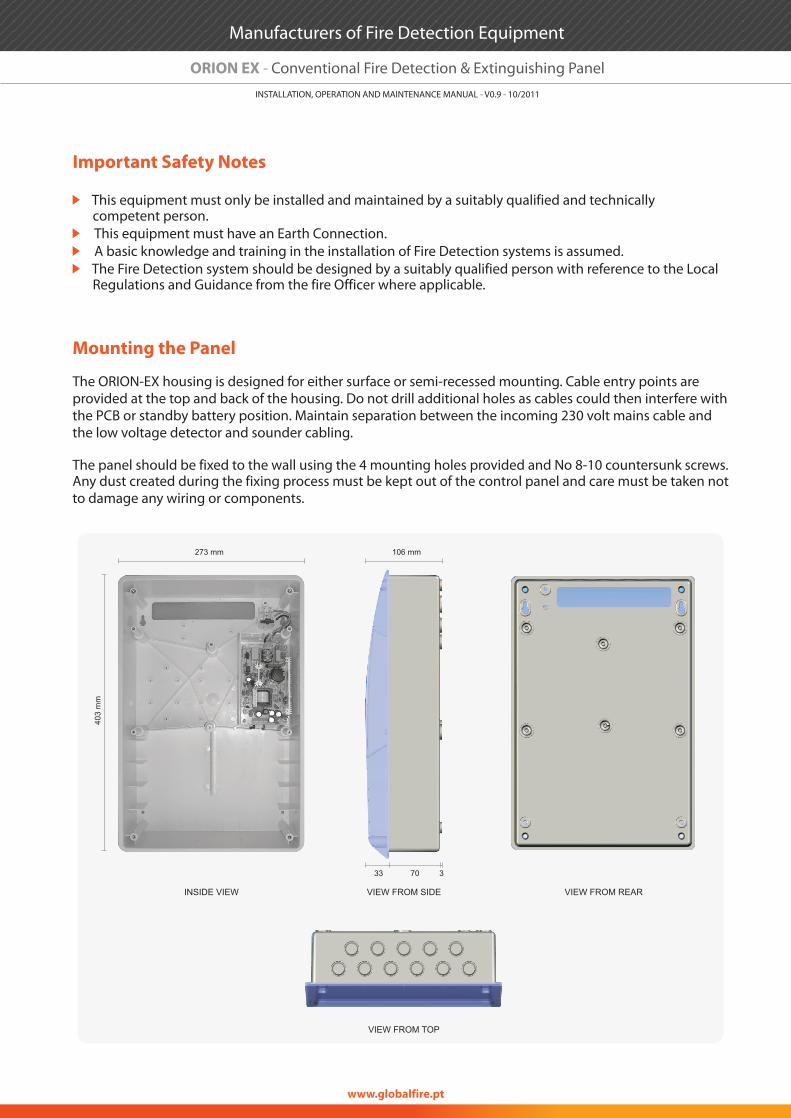
The ORION-EX housing is designed for either surface or semi-recessed mounting. Cable entry points are provided at the top and back of the housing. Do not drill additional holes as cables could then interfere with the PCB or standby battery position. Maintain separation between the incoming 230 volt mains cable and the low voltage detector and sounder cabling.
The panel should be fixed to the wall using the 4 mounting holes provided and No 8-10 countersunk screws.Any dust created during the fixing process must be kept out of the control panel and care must be taken not to damage any wiring or components.
Manufacturers of Fire Detection Equipment
www.globalfire.pt
INSTALLATION, OPERATION AND MAINTENANCE MANUAL - V0.9 - 10/2011
ORION EX - Conventional Fire Detection & Extinguishing Panel

Connecting the Panel
Before connecting zone or sounder cables, power up the control panel with the Active EOL connected to the zone inputs and the EOL resistors for the sounder lines connected. Connect mains and battery power; there should be no fault indications.
The mains supply should be routed away from the other cables and enter the control panel adjacent to the mains terminal block.
Wiring to the Mains supply should only be undertaken by a suitably qualified and competent person.
Depending on panel load and standby requirements, two 12 volt valve regulated lead acid batteries of capacity up to 7Ah may be fitted in the housing. The batteries should be wired in series (24 V) using the supplied link. Take care not to short circuit the battery terminals.
Check zone, remote input and sounder wiring for continuity. Short or open circuit indications must be rectified before connecting to the control panel. All cable testing must be carried out with a Multi meter….NEVER use a Megger when devices are connected.
Induced voltage higher than 1 Volt indicates possible cable problems or bad earth connection and must be rectified before connection.
Transfer Active EOL modules and EOL resistors to the last device on Detection and sounder circuits and connect the cables to their respective terminals in the control panel. See Diagram below.
A B
Manufacturers of Fire Detection Equipment
www.globalfire.pt
INSTALLATION, OPERATION AND MAINTENANCE MANUAL - V0.9 - 10/2011
ORION EX - Conventional Fire Detection & Extinguishing Panel
A Zones
Auxiliary Supply Outputs - 28V DC @ 300 mAK
B Monitored Inputs
C Remote Input - Instant Activate Extinguishing
D Remote Input - Instant Abort Extinguishing
E Sounder Circuits
F Auxiliary Relay - Fire
G Auxiliary Relay - Fault
H Remote Inputs - not monitored
I Remote Reset
Monitored Open Collector OutputJ
C D E F G H I J K
Cable Types
Detection Zone Wiring
System wiring should be installed in accordance with National Standards and wiring regulations.
To protect against electrical interference we recommend the use of screened cables throughout the system. Separate cables should be used for sounder and detection circuits, the use of multi-core cables to carry sounder circuits and detector circuits is not recommended. The cable screens should be terminated and connected to Earth at the panel only. Maximum cross section of cables to use is 2.5mm² to avoid damaging the terminals in the control panel.
Mains wiring should be 3 core 1mm² to 2.5mm² fed from an isolating fused spur, fused at 3A. This should be secure from unauthorized operation and be marked “Fire Alarm Do Not Switch Off” The mains supply must be exclusive to the fire panel.
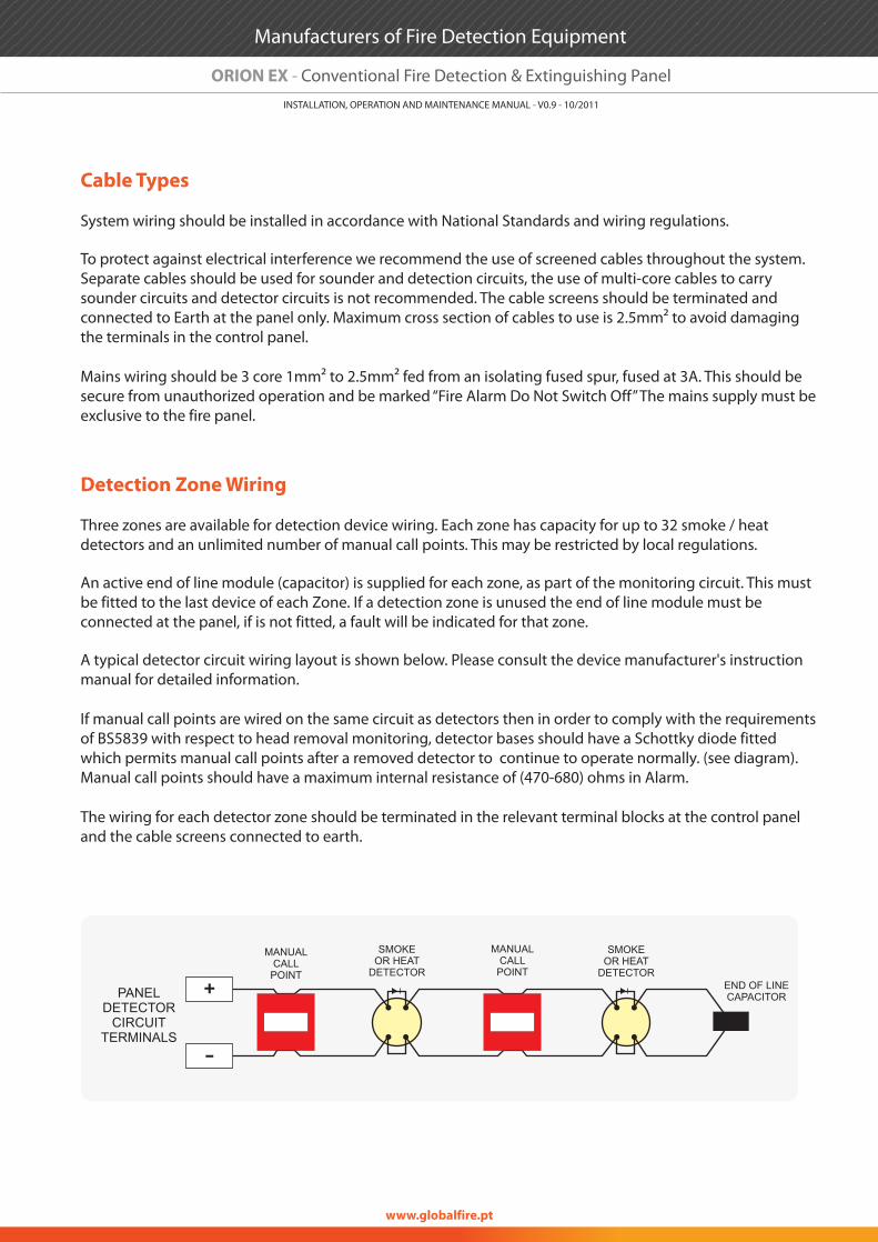
Three zones are available for detection device wiring. Each zone has capacity for up to 32 smoke / heat detectors and an unlimited number of manual call points. This may be restricted by local regulations.
An active end of line module (capacitor) is supplied for each zone, as part of the monitoring circuit. This must be fitted to the last device of each Zone. If a detection zone is unused the end of line module must be connected at the panel, if is not fitted, a fault will be indicated for that zone.
A typical detector circuit wiring layout is shown below. Please consult the device manufacturer's instruction manual for detailed information.
If manual call points are wired on the same circuit as detectors then in order to comply with the requirements of BS5839 with respect to head removal monitoring, detector bases should have a Schottky diode fitted which permits manual call points after a removed detector to continue to operate normally. (see diagram). Manual call points should have a maximum internal resistance of (470-680) ohms in Alarm.
The wiring for each detector zone should be terminated in the relevant terminal blocks at the control panel and the cable screens connected to earth.
MANUALCALLPOINT
SMOKEOR HEAT
DETECTOR
SMOKEOR HEAT
DETECTOR
MANUALCALLPOINT
END OF LINECAPACITORPANEL
DETECTORCIRCUIT
TERMINALS
Manufacturers of Fire Detection Equipment
www.globalfire.pt
INSTALLATION, OPERATION AND MAINTENANCE MANUAL - V0.9 - 10/2011
ORION EX - Conventional Fire Detection & Extinguishing Panel

Sounder Circuit Wiring
Auxiliary Input Wiring - Not Monitored
There are two conventional sounder circuits available on the ORION-EX. The maximum current available for sounders is (500 mA) per circuit. All sounders must be polarized, non-polarized sounders will indicate a fault on the sounder circuit.
An end of line resistor (10 K Ohm) which is supplied with the panel, must be inserted in the last sounder for cable monitoring. If a sounder circuit is not used, the EOL resistor should be fitted in the control panel sounder output.
The sounder circuits are protected against short circuits, the electronic fuse will reset when the short circuit is removed and the control panel is reset.
The wiring for each sounder circuit should be terminated in their respective terminals and the cable screens connected to earth.
Typical sounder circuit wiring diagram:
There are on the Orion-EX-L remote activation inputs. All remote inputs are activated using a voltage free dry contact like a relay or manual ON-OFF switch.
Reset The closure of a contact at this input will cause the panel to reset. In order to reapply a reset to the panel, contact has to be released and reapplied. Pulse action.
Evacuate Activates sounders immediately when 0V is applied via a voltage free contact. Sounders active LED is illuminated, Sounders continue to operate until the input is removed. Pressing the Silence button will stop the sounders.
The wiring for each auxiliary input should be terminated in their respective terminals and the cable screens connected to earth.
DE Not used. Reserved for future functionalities.
POLARIZEDSOUNDER
END OF LINERESISTOR10K Ohm
POLARIZEDSOUNDER
POLARIZEDSOUNDER
SOUNDERCIRCUIT
TERMINALS
Manufacturers of Fire Detection Equipment
www.globalfire.pt
INSTALLATION, OPERATION AND MAINTENANCE MANUAL - V0.9 - 10/2011
ORION EX - Conventional Fire Detection & Extinguishing Panel

Auxilliary Monitored Inputs
Ouputs
EV This input is used to monitor and signal the panel the status of the electrovalve associated with the extinguishing system. Faults are signaled via the associated yellow LED. An active EOL is used to monitor the status of the lines. Activation of this input is accomplished using a normally open (NO) voltage free contact in series with a resistor with a value in the range 470 to 1000 Ohms. The red LED will be activated when the contact is closed.
PSTextinguishing system. Faults are signaled via the associated yellow LED. An active EOL is used to monitor the status of the lines. Activation of this input is accomplished using a normally open (NO) voltage free contact in series with a resistor with a value in the range 470 to 1000 Ohms. The red LED will be activated when the contact is closed.
NOTE: The following inputs are disabled. Te EOL capacitor provided should be fitted to each input.
Auxiliary Power 28V DC max 300 mA, short circuit protected, supervised. The output is protected
against short circuit by an electronic fuse which resets when the fault is cleared and the panel is reset.
Relay Contact Fire Provide Fire signal to external devices. Relay contact changeover 30V /1A max resistive. Active until Reset.
Relay Contact Fault Provide Fault signal to external devices.
Relay contact NC 30V / 1A max resistive.Also Active for microprocessor fault.Active until Reset and all faults are cleared.Relay contact will open when any fault is present on the system.
The wiring for each output should be terminated in their respective terminals and the cable screens connected to earth.
Repeater Output Multiplexed Fire and Fault indication per zone. Remote system command.Interface cards available for RS-485, Fibre Optics and TCP/IP (LAN) connection.
RM Open collector output. Active during the extinguishing cycle.
This input is used to monitor and signal the panel the status of the pressostat associated with the
INST To be used to active the extinguishing cycle. Close switch to activate.
ABORT To be used to active the extinguishing cycle. Close switch to activate.
Z8 Do not use. To be used in future versions of the ORION-EX panel. Fit the EOL capacitor to the terminals of this input.
Manufacturers of Fire Detection Equipment
www.globalfire.pt
INSTALLATION, OPERATION AND MAINTENANCE MANUAL - V0.9 - 10/2011
ORION EX - Conventional Fire Detection & Extinguishing Panel
Commissioning
The ORION-EX is supplied ready to operate as a standard conventional Fire Alarm control panel. Optional functions and their programming are described in the next section. If required they may be programmed before continuing with the commissioning.
The default settings for the ORION -EX-L are as follows:
All zones LatchingNo timers are programmedAuthorized User Access Code (Level 2) : 2244Alternatively access to Level 2 can be entered using the provided.Programming Access Code (Level 3) : 4321
Preparation
1º Check detector cables and ensure all field connections are made, ensure that all EOL devices are fitted to the last detector, call point or sounder of each circuit. EOL Capacitors should be fitted to zones or remote monitored inputs. EOL Resistors should be applied to sounder circuits.
2º Connect detector and sounder lines or terminate with EOL.
3º Remove the mains fuse.
4º Connect mains supply according to local mains voltage. Ensure good earth connection
5º Fit batteries (do not connect)
6º Insert mains fuse
7º Connect batteries - observe correct polarity
Commissioning
1º If all is normal only the Green “supply” LED should be illuminated.
2º If any Faults are indicated they should be corrected before proceeding
3º Initiate lamp test and check all LEDs operate and internal buzzer sounds
4º Test each key for correct functioning
5º Test all detectors, manual call points, sounders, relays etc. for proper operation
Access Key
Manufacturers of Fire Detection Equipment
www.globalfire.pt
INSTALLATION, OPERATION AND MAINTENANCE MANUAL - V0.9 - 10/2011
ORION EX - Conventional Fire Detection & Extinguishing Panel

Testing Field Equipment
Testing Smoke Detectors
1º Set zones to Test mode2º Introduce test smoke into the detector3º Wait until response indicator on detector indicates Red4º Automatic reset after (10 sec) / when smoke has cleared
Testing Heat Detectors
1º Set zones to Test mode2º Place test unit on head and turn on heat3º Wait until response indicator on detector indicates Red4º Automatic reset after (10 sec)
Testing Manual Call Points
1º Set zones to Test mode2º Activate Call point using the manufacturers instructions3º Wait until response indicator on call point indicates Red4º Reset the call point5º Automatic reset after (10 sec)
After testing is completed be sure to return control panel to normal operating mode.
Pressing RESET button will EXIT TEST mode
Testing Sounder Circuits
1º Initiate sounder test by entering Access Level 2 and pressing Sounders Activate/ Silence2º Press again to stop
Testing Relay Outputs
With the system in normal operating mode activate the Alarm and confirm operation of relays and external devices at the end of any programmed delay.
Manufacturers of Fire Detection Equipment
www.globalfire.pt
INSTALLATION, OPERATION AND MAINTENANCE MANUAL - V0.9 - 10/2011
ORION EX - Conventional Fire Detection & Extinguishing Panel

Operating & Programming The Panel
General user controls
The ORION-EX has a number of programmable options to help the engineer customize the system to meet the customer's requirements. To access these options it is necessary to enter access level three.
There are three levels of Access on the ORION-EX:
Level 1:
-Perform a lamp test-Silence Internal buzzer-Put the panel into Access Level 2 or 3 if in possession of the required access code.
-------
1º Outputs2º Zones and Monitored Inputs3º Activate Extinguishing Cycle4º Abort Extinguishing Cycle
When any zone or function is disabled the Disabled LED on the STATUS area of the Control Panel display, will be lit, together with the corresponding function or zone disablement LED. Disabled zones will have their corresponding FAULT/ DISABLED LED illuminated.
Level 2 Access is gained by entering the code 2244 using the numbered buttons. When in panel is in Level 2 the green LED will flash with a frequency of 1 Hz.
Each successful button press is indicated by the illumination in succession of the Fault LEDs for zones 3,4,5 and 6. If the code is not completed within 20 seconds of the last key press, the system reverts to level 1.
NOTE: If any Fire or Fault events have occurred these must be acknowledged by pressing the Buzzer Silence button to acknowledge each Fault or Fire event before code entry will be accepted.
Level 2:
This higher level allows the user to:
Silence and resound the soundersReset after an Alarm or FaultManually activate the sounders (Evacuate function)Silence Internal BuzzerTest the indicator lightsDisable or Enable any or all of the detection zonesDisable/ Enable the following:
Level 3:
It is accessed from Level 1 and allows:
- System Test- Extinguishing Timers Configuration
Authorised user controls (User 2244) or ACCESS KEY
Engineer controls for use by trained and competent personnel only .Access Code 4321
Manufacturers of Fire Detection Equipment
www.globalfire.pt
INSTALLATION, OPERATION AND MAINTENANCE MANUAL - V0.9 - 10/2011
ORION EX - Conventional Fire Detection & Extinguishing Panel

NOTES
Changes made at this level affect the factory default settings and the operation of the system. They should only be made by qualified personnel who are fully aware of their effects.If any Fire or Fault events have occurred, these must be acknowledged by pressing the Buzzer Silence button to acknowledge each fault and Fire event before code entry will be accepted.When in Access Level 3, the occurrence of any Fire or Fault condition the system will automatically exit from Level 3 and revert to Level 2.
To enter Engineering Mode (Access Level 3) enter the factory programmed code, using the numbered keys (from 1 to 4), which are available on the top right hand side of the control panel display.Each successful button press is indicated by the illumination in succession of the Fault LEDs for zones 3,4,5 and 6. If the code is not completed within 20 seconds of the last key press, the system reverts to Level 1.
Once this mode is entered the GREEN LED (SUPPLY) will flash once every 0,5 seconds.
To exit this mode at any time, press the RESET button. The panel will revert to Access Level 1.
Total removal of power during the programming phase may lose the changes entered.
consecutively until the time required has its FAULT LED lit up. Confirmation of this selection is achieved by pressing GREEN (1) key. Upon confirmation the RED (FIRE) LED will be turned ON.
1º
2º
3º
Programmable Options
Pre-Extinguishing Timer
After accessing Level 3, press ZONES switch. The associated LED will be activated. Select the required time delay by pressing the RED switch (4)
Remove selection by pressing the GREEN key againa. The corresponding LED will be switched OFF. To exit the function press ZONES switch. The programmed delay time is calculated multiplying by 10, the binary digit represented by the total number of RED LEDs lit. Each count represents 10 seconds .
Example
In order to create a delay of 10 seconds only the FIRE LED for zone 1 should be lit. On the other hand a time delay of 30 seconds will be represented by FIRE ZONE LEDs 1 and 2 being lit. When all FIRE-ZONE LEDs are lit, a delay of 255 x 10 seconds is programmed. This corresponds to approximately 42.5 minutes.
Manufacturers of Fire Detection Equipment
www.globalfire.pt
INSTALLATION, OPERATION AND MAINTENANCE MANUAL - V0.9 - 10/2011
ORION EX - Conventional Fire Detection & Extinguishing Panel

Extinguishing TimerAfter accessing Level 3, press ACTIVATE EXTINGUISHING switch. The associated LED will be activated. Select the required time delay by pressing the RED switch (4) consecutively until the time required has its FAULT LED lit up. Confirmation of this selection is achieved by pressing GREEN (1) key. Upon confirmation the RED (FIRE) LED will be turned ON. Remove selection by pressing the GREEN key again. The corresponding LED will be switched OFF. To exit the function press ZONES switch. The programmed delay time is calculated multiplying by 10, the binary digit represented by the total number of RED LEDs lit. Each count represents 10 seconds .
Example
In order to create a time of 10 seconds only the FIRE LED for zone 1 should be lit. On the other hand a timer with a duration of 30 seconds will be represented by FIRE ZONE LEDs 1 and 2 being lit. When all FIRE-ZONE LEDs are lit, a delay of 255 x 10 seconds is programmed. This corresponds to approximately 42.5 minutes.
One man Test
After entering Engineering Mode (Access Level 3) press the LAMP TEST button. Release button and the TEST LED will be on along with the fault LED for all zones that are available for testing indicating that the panel is in TEST mode. Zones that are in Fault or are Disabled will not have their LED illuminated.
Test zones as required. At each zone activation, the corresponding zone FIRE LED will light up for 5 seconds. Zones will automatically reset after 10 seconds. Internal Buzzer and SOUNDERS will operate for 1 second.
To end TEST mode press LAMP TEST button.
To exit Engineering Mode (Access Level 3), press the RESET button.
Manufacturers of Fire Detection Equipment
www.globalfire.pt
INSTALLATION, OPERATION AND MAINTENANCE MANUAL - V0.9 - 10/2011
ORION EX - Conventional Fire Detection & Extinguishing Panel

FIRE
FAULT
SUPPLY
BATTERY
SOUNDERS
EARTH
BUZZERSILENCE
RESET
LAMP TEST
SOUNDERSACTIVATE/
SILENCE
OUTPUTS
ZONES
ACTIVATE
ABORT
STATUS
FAULTS DISABLEMENTS
CONTROLS
DISABLED
TEST
SUPPLY
SYSTEMFAULT
ACCESS
MANUFACTURED IN THE E. TO THEREQUIREMENTS OF EN 54-2, EN 54-4 & EN 12094-1
U.
1
2
3
EV
PS
REL
EXT
REM
VALVE
PRESSURE SWITCH
AUXILIARY RELAYS
EXTINGUISHING
REMOTE O/P
EXTINGUISHING
2
1
3
4
1 2 3
ZONES EXTINGUISHING STATUS
ON
OFF
EV PS REL EXT REM
The Panel Buttons
STATUS
FIRE LED used to indicate any FIRE ALARM condition present on panel.
FAULT LED used to indicate any FAULT condition present on panel.
DISABLED Disabled Status LED used to indicate that the panel has features that have been disabled in either Access Level 2 or 3 modes.
TEST This LED is active whenever panel is in TEST MODE. Only LIT when in Engineering Mode and TEST mode has been selected.
SUPPLY Multi function indicator used to indicate the presence of supply. When in Access Level 1 this LED is permanently lit. If in Access Level 2 (enter this mode using USER CODE) this LED will flash at a rate of once per second. And finally if in Access Level 3 mode (enter using ENGINEERING CODE) this LED will flash faster at a rate of once every 0,5 seconds.
SYSTEM FAULT This LED will be lit whenever there is a processor failure or corruption of the panel firmware.
FAULTS
SUPPLY FAULT This LED will be ON whenever the Main Supply has been removed or has dropped below 20 Volts.
BATTERY FAULT Indicates that there is low voltage level on the batteries or the battery charger circuit has failed.
Manufacturers of Fire Detection Equipment
www.globalfire.pt
INSTALLATION, OPERATION AND MAINTENANCE MANUAL - V0.9 - 10/2011
ORION EX - Conventional Fire Detection & Extinguishing Panel

SOUNDER FAULT If there is a conventional sounder circuit fault, the General Fault LED will be lit and the Disable Sounders LED in the disablements section will also be lit and flashing.
EARTH FAULT When this indicator is ON there is leakage current flowing from the earth connection/ wiring and any conductor in coming into the panel.
Individual zone and monitored input indicators are provided for both FIRE/ALARM and FAULT conditions. If any of these inputs is disabled then its FAULT LED will also be used to indicate the disablement of that particular zone/ input. The Zone/ Input Disabled LED will be ON along with the associated Disabled status LED. Flashing Fault LED along with General fault LED indicates fault on that zone.
CONTROLS
These four keys can have more than one function.
They are numbered to indicate that they are used to enter digits from 1 to 4 for code entry.
BUZZER SILENCE ( 1 ) At Access Level 1 this button is used to silence the panel's internal buzzer. Access level 3 used to confirm/accept changes in programming.
RESET ( 2 ) Press this button to reset the panel at access level 2 or 3.
LAMP TEST ( 3 ) Press this button at access level 1 or 2 to test all LED indicators and the panel's internal buzzer. Release when test is finished.
SOUNDERS ( 4 ) Press once to activate/silence sounders. If sounders are active, for example, during a FIRE condition or in the event of an Evacuation action, pressing this button will stop the sounders. Auxiliary Relays are not affected by this action. Used in Access level 3 programming to select Zones
ZONE & INPUT INDICATORS
DISABLEMENTSThese switches will only be active in Access Level 2.
OUTPUTS Press this button to enable/ disable a particular output. LED will also be lit. Select the required output by pressing consecutively the RED BUTTON (4) until the FAULT LED for the required output is lit. Confirm selection by pressing the GREEN BUTTON (1). The corresponding RED LED will be lit. Remove selection by pressing again the GREEN BUTTON (1). The associated RED LED will be OFF. To exit function repeat OUTPUTS switch press.
When switch is pressed associated
Manufacturers of Fire Detection Equipment
www.globalfire.pt
INSTALLATION, OPERATION AND MAINTENANCE MANUAL - V0.9 - 10/2011
ORION EX - Conventional Fire Detection & Extinguishing Panel

Zones
Use this button to disable zones 1, 2 and 3. When switch is pressed associated LED will also be lit. Select the required ZONE by pressing consecutively the RED BUTTON (4) until the FAULT LED for the required ZONE is lit. Confirm selection by pressing the GREEN BUTTON (1). The corresponding RED LED will be lit. Remove selection by pressing again the GREEN BUTTON (1). The associated RED LED will be OFF. To exit function repeat ZONES switch press.
1
3
2
Disable Zones
ON
OFF
ZONE 1
NOT USED
ZONE 2
ZONE 3
NOT USED
Outputs
The RED LED when lit indicates which output is disabled.
The yellow LED is used which output is presently selected to ENABLE/ DISABLE.
When there are any outputs disabled, the yellow LED associated with the outputs button will be lit.
NOT USED
1
3
2
Disable Outputs
ON
OFF
FIRE RELAY
SOUNDERS
SIRENES 2 + REM
NOT USED
NOT USED
NOT USED
NOT USED
NOT USED
NOT USED
NOT USED
Manufacturers of Fire Detection Equipment
www.globalfire.pt
INSTALLATION, OPERATION AND MAINTENANCE MANUAL - V0.9 - 10/2011
ORION EX - Conventional Fire Detection & Extinguishing Panel

Extinguishing Cycle
The extinguishing cycle can be initiated using two different approaches:
a) Coincidence of Zone 1 and 2
When both zones 1 and 2 are in Fire condition, the pre-extinguishing delay is initiated, if previously programmed. Sounder Circuit 1 is activated inmediately with each zone activation. Sounder Circuit 2 and output RM will be active for the duration of the programmed extinguishing time but only after the pre-extinguishing time has elapsed. Sounder Circuit 1 is silenced using Sound/ Resound Alarms button.
If no extinguishing delay has been programmed, both sounder circuits and output RM will activated inmediately for the duration of the programmed extinguishing cycle. When this timer elapses both Sounder Circuit 2 and output RM will be de-activated.
FIRE LEDs for zone 1 and 2 will be active. With each fire activation the SOUNDERS RED LED will be activated. When the extinguishing is active both EXTINGUISHING and REMOTE O/P RED LEDs will be lit .
b) Manually
The extinguishing process can be controlled manually using the buttons available on the panel’s front display.
The extinguishing cycle can be initiated manually executing the following steps:
a) In level 1, silence the internal buzzer using the INTERNAL BUZZER SILENCE button if there are any Fire or Fault conditions which have not been acknowledged.
b) If panel is in access level 1, access level 2 by using either the access key provided or by entering the user code 2244.
c) In order to activate the extinguishing press the ACTIVATE EXTINGUISHING button for aproximately 5 seconds. Activation is confirmed after the internal buzzer sounds for 1 second. Extinguishing outputs will activated inmediately for the duration of the previously programmed extinguihing time. Sounder Circuit 1 will also be activated. When the extinguishing cycle is initiated manually, the pre-extinguishing delay is not obeyed.
The extinguishing cycle can be stopped once initiated bypressing the ABORT EXTINGUISHING button.
Sounder Circuit 1 is silenced using Sound/ Resound Alarms button upon entering access level 2. The LED associated with this button will be OFF.
ACTIVATE
ABORT
EXTINGUISHING
Manufacturers of Fire Detection Equipment
www.globalfire.pt
INSTALLATION, OPERATION AND MAINTENANCE MANUAL - V0.9 - 10/2011
ORION EX - Conventional Fire Detection & Extinguishing Panel

Troubleshooting - Fault Indications
General Fault The General fault LED is illuminated whenever there is a fault on the system. It is always lit along with at least one other fault indicator which gives more detail relating to the fault.
Zone Fault This type of fault will indicate that there is either a short or open circuit condition on zone circuit. Revise wiring.
Power Supply Faults
Supply Fault Associated with a low voltage (below 20 V) present at the input of the power supply or the removal of the main power supply. Measure voltage levels and verify electrical mains fuse.
Battery Fault This fault is present when there is a low voltage below 20 V DC at the battery terminals or if there is a battery charger problem. Charger problems can be caused by panel's hardware failure or batteries that have not been connected in the specified manner as indicated in this manual, on the installation section. Verify if batteries are properly connected. Measure the voltage at the battery terminals. If it is below 21V DC replace batteries. Remember to verify also the main electrical fuse.
Earth Fault This FAULT will indicate that there is some level of current leakage between any of the wire conductors and the EARTH connections. VERIFY WIRING.
System Fault This FAULT indicates that there is a fault at the main processor level. In this particular fault, the panel's main board needs to be replaced or repaired.
Troubleshooting work of any fault on the panel should only be carried out by qualified technicians.
DON'T EVER SHORT CIRCUIT BATTERY TERMINALS IN ORDER TO VERIFY BATTERY CHARGEONLY USE BATTERIES WHICH ARE LEAD ACID VRLA TYPE 12 V DC.
Manufacturers of Fire Detection Equipment
www.globalfire.pt
INSTALLATION, OPERATION AND MAINTENANCE MANUAL - V0.9 - 10/2011
ORION EX - Conventional Fire Detection & Extinguishing Panel
Standby Battery Calculation
Min battery capacity 2 x 2 Ah 12 V DC
Max Battery capacity 2 x 7 Ah 12 V DC
Always use Lead- acid VRLA Batteries
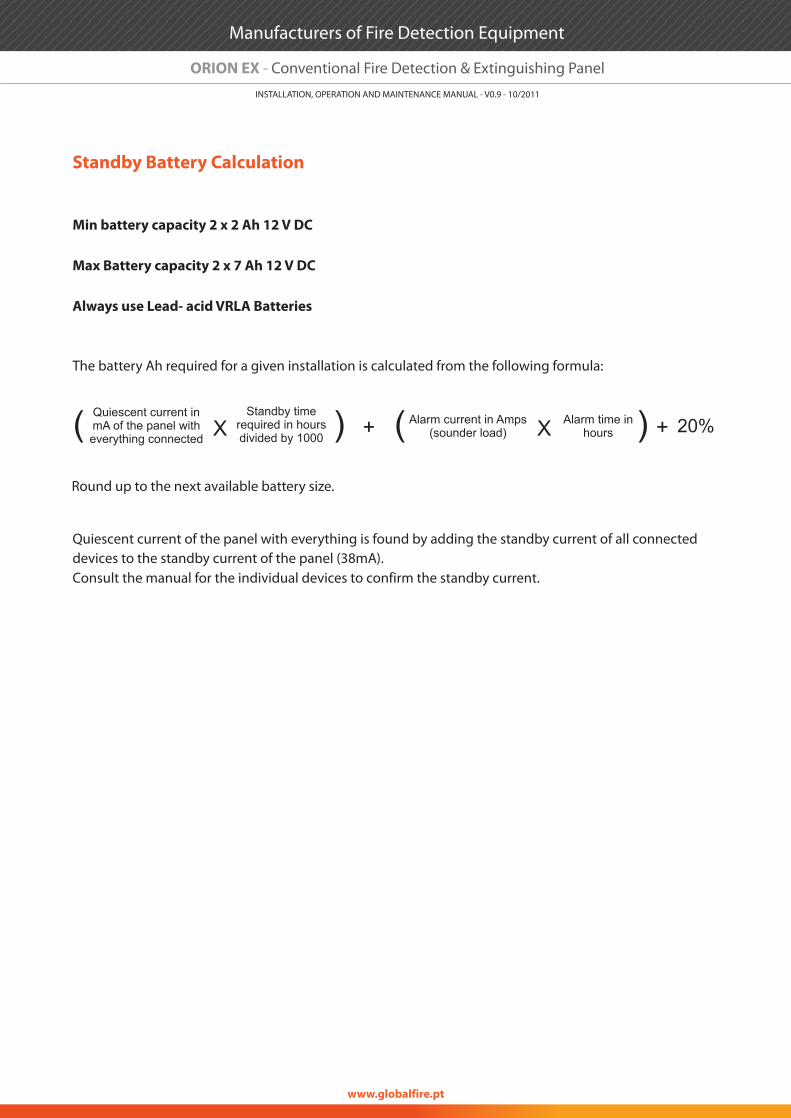
The battery Ah required for a given installation is calculated from the following formula:
Quiescent current of the panel with everything is found by adding the standby current of all connected devices to the standby current of the panel (38mA).Consult the manual for the individual devices to confirm the standby current.
Quiescent current in mA of the panel with everything connected
Alarm current in Amps (sounder load)
Standby time required in hours divided by 1000
Alarm time in hoursXX( () )+ + 20%
Round up to the next available battery size.
Manufacturers of Fire Detection Equipment
www.globalfire.pt
INSTALLATION, OPERATION AND MAINTENANCE MANUAL - V0.9 - 10/2011
ORION EX - Conventional Fire Detection & Extinguishing Panel
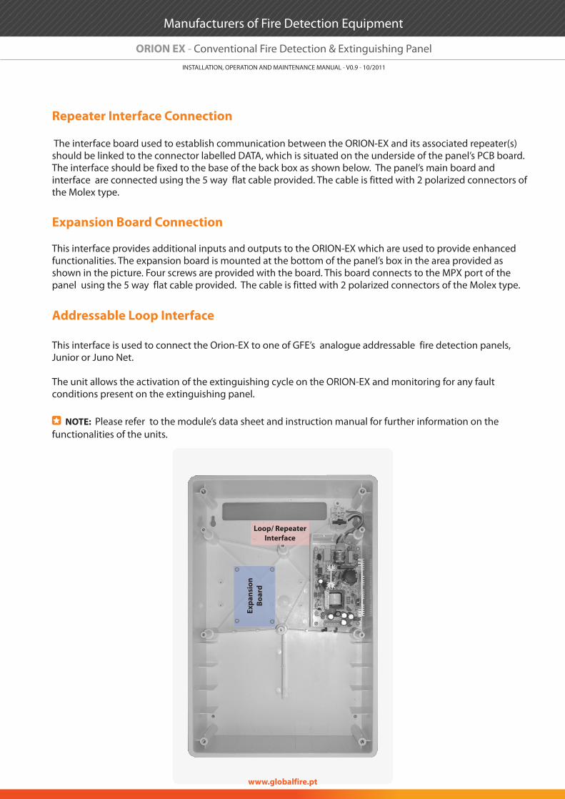
Repeater Interface Connection
Expansion Board Connection
Addressable Loop Interface
The interface board used to establish communication between the ORION-EX and its associated repeater(s) should be linked to the connector labelled DATA, which is situated on the underside of the panel’s PCB board. The interface should be fixed to the base of the back box as shown below. The panel’s main board and interface are connected using the 5 way flat cable provided. The cable is fitted with 2 polarized connectors of the Molex type.
This interface provides additional inputs and outputs to the ORION-EX which are used to provide enhanced functionalities. The expansion board is mounted at the bottom of the panel’s box in the area provided as shown in the picture. Four screws are provided with the board. This board connects to the MPX port of the panel using the 5 way flat cable provided. The cable is fitted with 2 polarized connectors of the Molex type.
This interface is used to connect the Orion-EX to one of GFE’s analogue addressable fire detection panels, Junior or Juno Net.
The unit allows the activation of the extinguishing cycle on the ORION-EX and monitoring for any fault conditions present on the extinguishing panel.
NOTE: Please refer to the module’s data sheet and instruction manual for further information on the functionalities of the units.
Expa
nsio
nBo
ard
Loop/ RepeaterInterface
Manufacturers of Fire Detection Equipment
www.globalfire.pt
INSTALLATION, OPERATION AND MAINTENANCE MANUAL - V0.9 - 10/2011
ORION EX - Conventional Fire Detection & Extinguishing Panel
ORDER CODE DESCRIPTION
TECHNICAL SPECIFICATIONS ORION EX
PRIMARY SUPPLY VOLTAGE- INSUPPLY SPECIFICATION
PRIMARY SUPPLY CURRENT-OUTSECONDARY SUPPLY VOLTAGE
SECONDARY SUPPLY CURRENT OUTPUTINTERNAL BATTERY CAPACITY - MAXIMUM
MAINS FUSEBATTERY FUSE
FIRE DETECTION CIRCUIT SPECIFICATIONNUMBER OF FIRE CIRCUITS
ZONE CURRENT - QUIESCENT/ ALARM
AUXILIARY RELAY OUTPUT
MAX. HUMIDITY
MECHANICAL & OPERATING SPEC.
OPERATING TEMPERATUREWEIGHT
DIMENSIONS
EVACUATION and RESET
FULLY MONITORED INPUTSREMOTE INPUT SPECIFICATION
RELAY CONTACT RATING
AUXILIARY OUTPUTS SPECIFICATION
BS5839 DETECTOR REMOVAL COMPLIANT
MAX. CABLE RESISTANCE / CAPACITANCEEND OF LINE MONITORING
DEVICES PER ZONE
ALARM RESISTANCE VALUESOUNDER CIRCUIT SPECIFICATION
END OF LINE RESISTOR
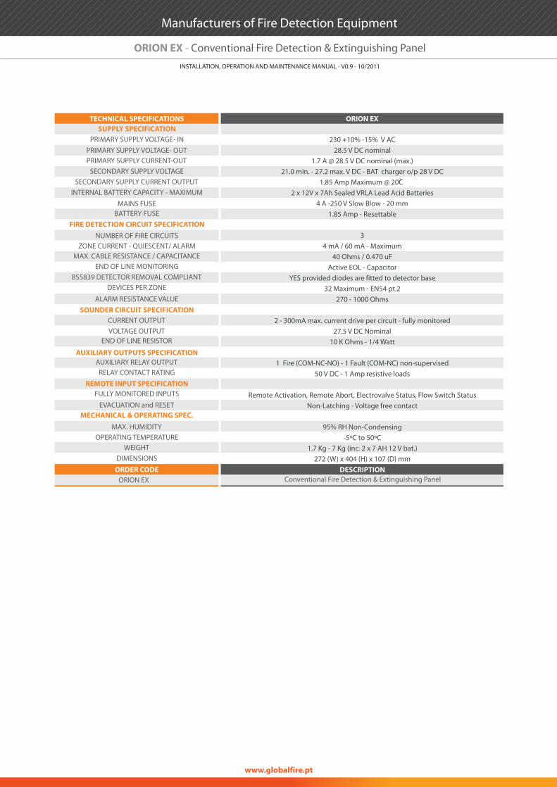
Conventional Fire Detection & Extinguishing PanelORION EX
PRIMARY SUPPLY VOLTAGE- OUT230 +10% -15% V AC
28.5 V DC nominal 1.7 A @ 28.5 V DC nominal (max.)
21.0 min. - 27.2 max. V DC - BAT charger o/p 28 V DC01.85 Amp Maximum @ 20C
2 x 12V x 7Ah Sealed VRLA Lead Acid Batteries4 A -250 V Slow Blow - 20 mm
1.85 Amp - Resettable
34 mA / 60 mA - Maximum
40 Ohms / 0.470 uFActive EOL - Capacitor
YES provided diodes are fitted to detector base32 Maximum - EN54 pt.2
270 - 1000 Ohms
2 - 300mA max. current drive per circuit - fully monitored27.5 V DC Nominal
10 K Ohms - 1/4 Watt
1 Fire (COM-NC-NO) - 1 Fault (COM-NC) non-supervised50 V DC - 1 Amp resistive loads
Remote Activation, Remote Abort, Electrovalve Status, Flow Switch StatusNon-Latching - Voltage free contact
95% RH Non-Condensing-5ºC to 50ºC
1.7 Kg - 7 Kg (inc. 2 x 7 AH 12 V bat.)272 (W) x 404 (H) x 107 (D) mm
CURRENT OUTPUTVOLTAGE OUTPUT
Manufacturers of Fire Detection Equipment
www.globalfire.pt
INSTALLATION, OPERATION AND MAINTENANCE MANUAL - V0.9 - 10/2011
ORION EX - Conventional Fire Detection & Extinguishing Panel


