42
Orion nCompass LC i4.3 Controller Configuration Manual RevE January 2014 (V1.9.4) Supersedes: Rev D (April 2013) Orion nCompass LC i4.3 Single/Dual Loop Controller Configuration Manual

Orion nCompass LC i4.3 Controller Configuration Manual RevE January 2014 (V1.9.4) Supersedes: Rev D (April 2013)
Orion nCompass LC i4.3 Single/Dual Loop Controller
Configuration Manual

nCompass i4.3
FDC nCompass Preface
Safety Information in this Manual Notes, cautions and warnings appear throughout this book to draw your attention to important operational and safety information. A “NOTE” marks a short message to alert you to an important detail. A “CAUTION” safety alert appears with information that is important for protecting your equipment and performance. A “WARNING” safety alert appears with information that is important for protecting you, others and equipment from damage. Pay very close attention to all warnings that apply to your application.
This symbol (an exclamation point in a triangle) precedes a general CAUTION or WARNING statement.
This symbol (a lightning bolt in a lightning bolt in a triangle) precedes an electric shock hazard CAUTION or WARNING safety statement.
Technical Assistance If you encounter a problem with your Orion nCompass controller, review all of your configuration information to verify that your selections are consistent with your application: inputs; outputs; alarms; limits; etc. If the problem persists after checking the above, you can get technical assistance by dialing +1 (866) 342-5332 or by faxing your request to +1 (866) 332-8014, Monday thru Friday, 8:00 a.m. to 5:00 p.m. Eastern Standard Time. You can also email your request to [email protected]. An applications engineer will discuss your application with you. Please have the following information available: • Complete Model #’s and/or Serial #’s for Component(s) in Question • Complete Software Version #’s • All Configuration Information • All User Manuals Warranty and return information is on the back cover of this manual.
Your Comments Your comments or suggestions on this manual are welcome. Please send them to: Future Design Controls, P.O. Box 1196, Bridgeview, Illinois, 60455 Telephone: +1 (888) 751-5444; fax: +1 (888) 307-8014 [email protected] The Orion nCompass LC i4.3 Single/Dual Controller Configuration Manual is copyrighted by Future Design Controls, Inc., © 2012, all rights reserved (http://www.futuredesigncontrols.com/nCompass.htm). .

nCompass i4.3
Table of Contents FDC nCompass i
1 What is nCompass?.............................................................................................................1.1 1.1 Features............................................................................................................................................... 1.1
2 Configurator Overview.........................................................................................................2.1 2.1 Configurator Menu............................................................................................................................... 2.2
3 Configuring nCompass........................................................................................................3.1 3.1 Loop Setup .......................................................................................................................................... 3.1 3.2 Loop Address Utility............................................................................................................................. 3.2 3.3 User Communications ......................................................................................................................... 3.3 3.4 Loop Configuration .............................................................................................................................. 3.4
3.4.1 Input Sensor Selection.................................................................................................................. 3.4 3.4.2 Input Unit Selection....................................................................................................................... 3.5 3.4.3 Decimal Point ................................................................................................................................ 3.5 3.4.4 Input Low/High Scale .................................................................................................................... 3.5 3.4.5 Input Filter ..................................................................................................................................... 3.6 3.4.6 Event Input Function ..................................................................................................................... 3.6 3.4.7 Low/High Setpoint Limits .............................................................................................................. 3.7 3.4.8 Output 1 Function.......................................................................................................................... 3.7 3.4.9 Output 1 Failure Transfer.............................................................................................................. 3.8 3.4.10 Output 1 ON-OFF Control Hysteresis ........................................................................................... 3.9 3.4.11 Output 1 Cycle Time ..................................................................................................................... 3.9 3.4.12 Output 1 Low/High Limit Values.................................................................................................... 3.9 3.4.13 Output 2 Function.......................................................................................................................... 3.9 3.4.14 Output 2 Failure Transfer............................................................................................................ 3.10 3.4.15 Output 2 Low/High Limit Values.................................................................................................. 3.10 3.4.16 Output 3 Function........................................................................................................................ 3.11 3.4.17 Output 3 Failure Transfer............................................................................................................ 3.11 3.4.18 Output 4 Function........................................................................................................................ 3.11 3.4.19 Output 4 Failure Transfer............................................................................................................ 3.12 3.4.20 Output 4 Low/High Limit Values.................................................................................................. 3.12 3.4.21 Output 4 Retransmit Low/High Scale.......................................................................................... 3.12 3.4.22 Alarm (1-3) Function ................................................................................................................... 3.13 3.4.23 Alarm (1-3) Mode ........................................................................................................................ 3.14 3.4.24 Alarm (1-3) Indication.................................................................................................................. 3.15 3.4.25 Alarm (1-3) Setpoint .................................................................................................................... 3.15 3.4.26 Alarm (1-3) Hysteresis ................................................................................................................ 3.15 3.4.27 Setpoint at Start of Automatic Program ...................................................................................... 3.16 3.4.28 Setpoint at End of Automatic Program ....................................................................................... 3.16 3.4.29 Power Fail Recovery ................................................................................................................... 3.17
3.4.29.1 Enabling Holdback................................................................................................................ 3.18 3.4.30 Loop Communication Mode ........................................................................................................ 3.20
3.5 Calibration.......................................................................................................................................... 3.21 3.6 Functions ........................................................................................................................................... 3.22 3.7 Startup View ...................................................................................................................................... 3.25 3.8 Alarm/Event Tagnames ..................................................................................................................... 3.26
3.8.1 Alarm Names .............................................................................................................................. 3.26 3.8.2 Event Names............................................................................................................................... 3.26
3.9 Custom Name\Address ..................................................................................................................... 3.27
Appendix Order Matrix Software License Software Usage Note Warranty
Returns


nCompass i4.3
What is nCompass? FDC nCompass 1.1
1 What is nCompass?
The nCompass system combines all of the features of a loop controller, video/chart recorder and data logging system into a single/intuitive device. Email, SMS (text messaging), FTP (file transfer protocol for automated data backup) and remote view/control (Web server/VNC server) are standard with nCompass and can be accessed via LAN/WAN using a PC, tablet or smart phone device. Future Designs “nCompass” provides a 4.3”color touch screen interface with standard “Smart Device” user interface features for single and dual loop OEM control applications. All loop configuration and runtime user access is configurable at the device with no PC software required. OEM’s have the ability to configure runtime features (screen availability, menus, language, etc...) to easily customize the system for their requirements. These configurations can be imported/exported to any other nCompass single/dual loop device for setup (from scratch) within minutes. Individual high performance board level PID loop control boards (one for each loop) offer up to four control outputs each, powerful profiling capabilities with up to three events and full auto tune functionality with high resolution process inputs. 1.1 Features
Each of the nCompass loop control boards provide a single digital input that can be programmed as a automatic program control input for run, hold or abort, a manual mode or failure transfer control input or a program advance to next segment control input. Each of the loop control boards also provide up to four control outputs which can be used as PID control outputs for heat/cool, direct outputs for controlling external equipment related to the application through software switches called events, or be programmed to act as system alarm outputs. nCompass can be operated in single set point or automatic program control mode. Program entry is made easy through the use of copy, paste and delete menu selections. Programs can be copied to the external USB memory stick and then imported to another nCompass controller which eliminates the need to enter duplicate programs into multiple systems. Data file analysis tools make looking at historical data a simple task. Any control variable saved to the data file can be plotted on the historical data chart for any time frame within the data file’s total time range. The built in Ethernet functionality includes a ‘Web Server’ to provide access to all nCompass data (view only), a VNC interface for remote control and monitoring and an NTS clock, all available via a local Intranet connection (wired or wireless), or the World Wide Web using standard software like Microsoft’s Internet Explorer. nCompass provides a rich set of tools for control interaction and process monitoring. Views include single and dual loop views, charts, alarm, automated program status as well as historical data, alarm log and audit trail views. The menu driven interface eliminates screen “clutter” by providing an easy to use “Smart Device” interface for interaction between the user and nCompass. nCompass can store more than one year of data on its SD memory card. Data logging can be enabled manually or automatically during program operation. Data backup is provided with a USB memory stick for plug and play transfer of files to any PC running Microsoft Windows XP operating systems and via the FTP back-up utility. nCompass protects system access with 4 level security (user rights based), audit trails that document all user activity and ensures data integrity by digitally signing all data files and audit trails to meet regulatory requirements.

nCompass i4.3
1.2 FDC nCompass What is nCompass?
The nCompass controller includes the following features:
• Single/Dual loop controller models (automatic program operation included). • Touch screen, “Smart Device” user interface (UI). • Video recorder mode for view only applications. • Email, SMS, FTP, VNC and Web functionality standard. • Remote View/Control using PC, Tablet or Smartphone. • Detailed maintenance, alarm monitoring and alarm history. • User configurable data logging and historical data viewer. • 4 level security with digitally signed audit trails and data files. • National time server connectivity with daylight savings. • Multi-lingual user interface supports over 25 languages. • 30,000 hour LED display

nCompass i4.3
Configurator Overview FDC nCompass 2.1
2 Configurator Overview
The nCompass configurator is a powerful tool that allows full customization of nCompass. It is a program that allows the OEM or user to set up control system options for the nCompass runtime application. The configurator program will not run at the same time as the main runtime software. The configurator can be run when the runtime software is exited and the “Exit and run configurator on next power-up” option is selected. The next time the unit is re-powered the configurator will run. Control functions of each loop control board can be changed while the OEM or operator is editing the configuration of nCompass through the configurator program, so any equipment being controlled by the outputs should be placed in an “off” state so that any changes will not cause an unsafe condition or damage to equipment. NOTE: Each time the nCompass configurator software is exited; the controller runtime software will run
after the unit is re-powered. The nCompass configurator provides the following functionality:
• Set the number of control loops that nCompass will use (single/dual). • Provide control loop configuration settings for input type, output function, set point range, etc. • Select the type of user communications for Modbus Slave interface. • ‘Splash Screen’ name editing for custom OEM or user requirements. • Enable/disable options for runtime menu and screen availability. • Text editing for all system event and alarm output names.

nCompass i4.3
2.2 FDC nCompass Configurator Overview
2.1 Configurator Menu
The configurator menu is accessed by pressing the “Monitor” icon at the top left of the screen.
The File menu provides the exit function for the configurator. After selecting this menu item and exiting the configurator, the controller runtime software will run after the unit is re-powered. The Setup menu provides access to the primary controller setup options. These options include the controller type (single/dual loop), the loop control board settings, user communications selection and the loop address utility that can be used to automatically assign the proper communications address to an attached loop control board. The Calibration menu provides access to the input offset calibration settings for the loop control boards. The Startup menu provides access to enable and disable nCompass runtime screens/menus and the desired startup view selection. The Tagnames menu provides access to the text editing functions of the configurator which allow the event and alarm names to be changed to match their use in the system. The menu also provides access to edit the splash screen information that is shown when the runtime application starts.

nCompass i4.3
Configuring nCompass FDC nCompass 3.1
3 Configuring nCompass
IMPORTANT: Once all configuration settings are made, you must select “Exit” from the File menu to exit the configurator prior to cycling power to nCompass. All configuration files are written upon exiting the configurator. Do not cycle power prior to exiting the configurator or settings will be lost and nCompass will not operate properly when entering the runtime application.
3.1 Loop Setup
The “Loop Setup” screen is accessed from the Setup menu. It provides the control type selection and entries for setting the loop names and display units.
The Control Type selection sets the number of loop control boards that will be attached to nCompass, one (single loop) or two (dual loop). When the nCompass runtime application is started, nCompass will automatically configure all loop view displays, charts and available data log point selections based on the control type selection and individual loop setup. The Loop Name fields are used to enter a specific name for each control loop, up to 11 characters in length. This name will be used throughout the nCompass runtime application and can be used to provide a more detailed description as to the function of the loop in the application. Default tag names are LOOP 1 and LOOP 2. The Units fields are used to enter the engineering units for the loop with up to four characters maximum. This value is shown on the single and dual view loop screens in the nCompass runtime application. When the loop input type selection is set for temperature, the field will be fixed at either “C” or “F” based on the units selection for the loop under loop setup. If the loop input type is set for a linear input type (0-10V or 4-20mA for example), the engineering units can be edited and changed to the required units for the measured process value.

nCompass i4.3
3.2 FDC nCompass Configuring nCompass
3.2 Loop Address Utility
In order for nCompass to properly communicate with each of the loop control boards, they must be configured for the proper communications address. The factory default communication settings of the loop control boards are set for a communications address of one, which correspond to the proper settings for loop 1. For a single loop nCompass control system, no further settings are required. Simply connect the communications wiring between the control board and the nCompass interface, and the system is ready to go. For a dual loop nCompass control system, one of the control boards must be set for address two which corresponds with loop 2 of nCompass. If a display module is not available to connect to the loop control board in order to set its address, the Loop Address Utility can be used. It is accessed from the Setup menu.
In order to use the utility, only one loop control board can be connected to nCompass at a time. Since the default address of all control boards are 1, if more than one was connected, they would both respond to the same command which would cause them both to be set to a different address. If both loop control boards are connected, disconnect the communications wiring from the loop control board that you DO NOT want to set the address on. An alternative is to remove power from the loop control board rather than disconnecting the communications wiring. With only one loop control board powered on or connected to nCompass via the communications link, press the “Assign to Loop” button for the loop that you want to assign the control board to. The utility will begin scanning for the loop control board and set its address to the proper address once found. If the utility fails to set the address, check the wiring to insure it is properly connected. If the loop control board has been previously used for another application, it may be possible that the address or other communications settings have been changed, which prevent the utility from working. In this case, a display module must be connected to the loop control board to set the proper communications settings: Address: 1 or 2 (for loop 1 or loop 2)
Baud rate: 9600 Parity: Even
IMPORTANT: The loop input number corresponds to the communications address that must be set in the
loop control board for nCompass to access it properly. If the communications address is not set properly in the loop control, nCompass will not be able to communicate with it, or may communicate with the wrong loop control and assign the incorrect set points and control parameters to it.

nCompass i4.3
Configuring nCompass FDC nCompass 3.3
3.3 User Communications
The Modbus slave interface of nCompass can be set to operate in one of two modes. The default setting is to provide the standard LC user interface for use with FDC’s Envision software. This selection assigns values to the Modbus slave register table in the proper positions to allow communications between EnVision and nCompass.
The second selection configures the Modbus slave interface to simulate the communications interface for a “Watlow F4S/D” controller. This selection assigns nCompass control values to the corresponding register addresses of a Watlow F4S/D controller allowing limited compatibility with Watlow’s WatView software. This provides current users of the F4 controller and WatView software a control option for the replacement for aging F4 controllers while keeping the common software interface without the need for training on the use of different software. IMPORTANT: The Watlow F4S/D interface is limited to basic set point adjustment, event output control,
profile operation and single profile download using WatView’s profile editor. Attempting unsupported functions may cause errors in the operation of WatView software and require it to be restarted.
See the nCompass LC i4.3 User Communications Reference Manual for details on the use of the Modbus slave interface including communications settings, register addresses and their associated values as well as the functionality of the selected interface type.
The F4S/D controller and WatView are registered trademarks of the Watlow Electric Manufacturing Company.

nCompass i4.3
3.4 FDC nCompass Configuring nCompass
3.4 Loop Configuration
The Loop 1 and Loop 2 Configuration screens are accessed from the Setup menu. The screens provide all settings related to the setup of the loop control boards. The up and down scroll (arrow) buttons allow the user to scroll through the list of configuration items for the loop. The list also supports touch-flow, so the user can simply touch the list and drag their finger up or down to scroll through the list items.
To change the setting for an item, select it from the list by touching it, and press the “Edit” button. If the entry is a simple numeric value, the number entry pad will be shown to allow the user to enter a new value. If the item has multiple selections available, a list of individual selections for the item will be shown that the user can then select from. 3.4.1 Input Sensor Selection
The Input Sensor Selection is used to select the type of sensor that will be connected to the loop control board. The input type can be a temperature input (thermocouple or RTD) or a linear input type (Vdc or mA). NOTE: The loop control board is ordered with either a standard input for thermocouples and RTD’s, a
voltage input or a milliamp input. The selected input type must be set to match the type of input supplied on the loop control board or the unit will not operate correctly.

nCompass i4.3
Configuring nCompass FDC nCompass 3.5
The input type selections are mutually exclusive, i.e., selecting one input will turn all other selections off. Once the desired input type has been selected, press the “Done” button to set the input type for the loop control board and return to the main Loop Setup screen. 3.4.2 Input Unit Selection
The Input Unit Selection is used to select the temperature units for temperature input types (thermocouple or RTD). If the selected input type is a linear input (Vdc or mA), the unit selection will default to process allowing user entry for engineering units for the loop on the Loop Setup screen.
The input unit selections are mutually exclusive, i.e., selecting one will turn off the other. Once the desired temperature units have been selected, press the “Done” button to set the input units for the loop control board and return to the main Loop Setup screen. 3.4.3 Decimal Point
The decimal point entry allows the input precision to be adjusted between 0 and 1 decimal digits for temperature input types, between 0 and 2 for a 0-60mV input and from 0 to 3 for Vdc and mA input types. IMPORTANT: Once the loop control board has been configured with a specific decimal point, changing the
decimal point will require the loop control board to be reconfigured in order to maintain previous control settings. Automatic programs, alarm set points, set point limits, input low/high scale, etc., DO NOT automatically scale. An entry of 100.0 becomes 1000 when changing the decimal point to zero (not 100), and must be re-entered to set the proper value.
3.4.4 Input Low/High Scale
The input low and high scale values are used to set the input range for linear input types (Vdc or mA). The entries are not available for temperature input types since they utilize a fixed range based on the sensor type. The input low scale value can be set from -32768 up to the high scale value minus 50. The high scale value can be set from the low scale value plus 50 up to 32767. NOTE: The minimum and maximum scale values are limited by the decimal point selection. For a decimal
of 0, the values are -32768 and 32767 respectively. For one decimal point, the values are -3276.8 and 3276.7. For two decimal digits, the values are -327.68 and 327.67 and for three decimal digits the values are -32.768 and 37.767.

nCompass i4.3
3.6 FDC nCompass Configuring nCompass
3.4.5 Input Filter
The Input Filter Selection is used to select the time constant to be used for filtering the process input.
The time constant selections are mutually exclusive, i.e., selecting one will turn off the others. Once the desired filter constant has been selected, press the “Done” button to set the input filter for the loop control board and return to the main Loop Setup screen. 3.4.6 Event Input Function
The Event Input Function is used to select the desired mode of operation for the digital input of the loop control board. The event input selections are mutually exclusive, i.e., selecting one will turn off the others. Once the desired function has been selected, press the “Done” button to set the event input function for the loop control board and return to the main Loop Setup screen. IMPORTANT: If nCompass is set for dual loop operation, both loop control boards must be set to the same
function and both inputs must be wired to the same control switch if automatic ramp/soak programs are to be used. If the input operation for both loop control boards is not identical, program operation of one loop may continue while the other may be terminated due to the input function selected. If program operation is not desired and will be disabled, then the event input functions do not have to match.

nCompass i4.3
Configuring nCompass FDC nCompass 3.7
The Automatic program run function is a single-shot action that will start the currently loaded program when the event input is activated. The Automatic program hold function will put the currently running program into hold when the event input is activated. The program will resume operation and return to the run mode when the input is deactivated. The Automatic program abort function is a single-shot action that will abort the currently running program. Note that the abort function does not work if the program is in hold. The program must be running in order for the abort function to work. The Manual mode function puts the loop control board into manual output mode when the input is activated. This stops all PID control action allowing the user to manually enter a fixed percentage of output. The loop control will return to normal PID control action when the input is deactivated. The Failure transfer function puts the loop control outputs into failure transfer mode when the input is activated. The output will then go to the percent output value set for failure transfer. The loop control outputs will return to normal PID control when the input is deactivated. The Automatic program advance next segment function is a single-shot action that will advance the currently running program by one step each time the event input is activated.
The Automatic program run/hold function is a combination of the automatic program run and program hold functions. Upon first activation of the input, the currently loaded program will be started if not already running. Deactivating the input will then cause the program to go into hold. The input must then be reactivated in order for the program to resume operation. NOTE: nCompass does not support the P41/B42 event input functions of “Off Mode” and “PID2 Select”.
These selections are not available through the nCompass configuration. 3.4.7 Low/High Setpoint Limits
The low and high set point limits are used to set the OEM minimum and maximum allowed set points that can be entered for the loop control. The minimum and maximum set point range is equal to the input range for the configured input type. NOTE: The runtime application provides additional user low and high set point limits. These can be
adjusted to further limit the allowable set point range within the band set by the OEM low and high set point limits.
3.4.8 Output 1 Function
The Output 1 Function is used to set the mode of operation for the primary control output of the loop control board. The output can be set for heating or cooling on/off control, time proportioning or linear control. The output selections are mutually exclusive, i.e., selecting one will turn off the others. Once the desired function has been selected, press the “Done” button to set the output function for the loop control board and return to the main Loop Setup screen. NOTE: The output function must be set to match the type of output ordered on the loop control board.
Relay, triac and SSR output types are used for on/off and time proportioning control. The isolated Vdc and mA output types are used for linear control.

nCompass i4.3
3.8 FDC nCompass Configuring nCompass
The Heating on-off control function will turn on the output when the process value is below set point. When the process value rises above the set point plus the on-off control hysteresis, the output will turn off. The Heating time proportioning function uses the PID settings to cycle the output on and off according to the percentage of heating required using the cycle time configured for output 1. For example, if the percentage of output is 50% and the cycle time is 18 seconds, the output will repeat on/off cycles of 9 seconds each. If the output was only 25%, the output would be on for 4.5 seconds and off for 13.5 seconds of the 18 second cycle time. The Heating linear control function uses the PID settings to vary the Vdc or mA output from the minimum to the maximum range of the output as a direct percentage of the heating output. The Cooling on-off control function will turn on the output when the process value is above set point. When the process value falls below the set point minus the on-off control hysteresis, the output will turn off. The Cooling time proportioning function uses the PID settings to cycle the output on and off according to the percentage of cooling required using the cycle time configured for output 1. For example, if the percentage of output is 50% and the cycle time is 6 seconds, the output will repeat on/off cycles of 3 seconds each. If the output was only 25%, the output would be on for 0.75 seconds and off for 5.25 seconds of the 6 second cycle time. The Cooling linear control function uses the PID settings to vary the Vdc or mA output from the minimum to the maximum range of the output as a direct percentage of the cooling output. 3.4.9 Output 1 Failure Transfer
The output 1 failure transfer setting is used to set the value the output should go to if there is an input failure, i.e., sensor break. The output can be set for bumpless (-1) operation or a fixed percentage of output (from 0 to 100%) if proportioning or linear control is selected fro the output function. When failure transfer is set to bumpless, the output will remain at its previous percentage of output until the input condition is corrected. Note that this should not be used for extended periods of time as a runaway condition could occur if separate limit devices are not installed to insure safe limits of operation by turning off the system should a limit be exceeded. If the output function is set for on-off control, the failure transfer can be set to have the output turn on (1) or turn off (0) when a sensor break occurs.

nCompass i4.3
Configuring nCompass FDC nCompass 3.9
3.4.10 Output 1 ON-OFF Control Hysteresis
The output 1 on-off control hysteresis can be set when the output 1 function is set for heating or cooling on-off control. It is used to eliminate rapid cycling of the control output by applying a safe-sided dead band to the control output. When the control set point is exceeded, the output will turn on. The output will not turn off until the process rises above (for heating) or falls below (for cooling) the set point by the hysteresis value. The hysteresis can be set from a minimum of 0.1 to a maximum of 50.0 for units of degrees Centigrade and to a maximum of 90.0 for units of degrees Fahrenheit and process units. 3.4.11 Output 1 Cycle Time
The output 1 cycle time can be set when the output 1 function is set for heating or cooling proportioning control. The cycle time can be adjusted from 0.1 to 90.0 seconds. For cycle times less than 18 seconds, it is highly recommended that the loop control board be ordered with the triac or SSR drive output for output 1 to extend the life of the control output. 3.4.12 Output 1 Low/High Limit Values
The output low and high limit values can be set when the output 1 function is set for heating or cooling time proportioning or linear control. They are used to set the minimum and maximum percentage of output that the output will control to with a default of 0% for the low and 100% for the high. By raising the low limit or reducing the high limit, the output will not exceed the output value regardless of the percent output required by the PID values. For example, raising the low limit to 5% with the output set for heating proportioning control, even if the process value is over set point and the PID values are calling for a 0% output, the output will continue to cycle on and off at 5% heating. 3.4.13 Output 2 Function
The Output 2 Function is used to set the mode of operation for the secondary control output of the loop control board. NOTE: The output function must be set to match the type of output ordered on the loop control board.
Relay, triac and SSR output types are used for proportioning control, alarm or event outputs. The isolated Vdc and mA output types are used for linear control.

nCompass i4.3
3.10 FDC nCompass Configuring nCompass
The output can be set for cooling time proportioning or linear control, as an alarm or an event. The output selections are mutually exclusive, i.e., selecting one will turn off the others. Once the desired function has been selected, press the “Done” button to set the output function for the loop control board and return to the main Loop Setup screen. The Cooling time proportioning function uses the PID settings to cycle the output on and off according to the percentage of cooling required using the cycle time configured for output 1. For example, if the percentage of output is 50% and the cycle time is 6 seconds, the output will repeat on/off cycles of 3 seconds each. If the output was only 25%, the output would be on for 0.75 seconds and off for 5.25 seconds of the 6 second cycle time. The Cooling linear control function uses the PID settings to vary the Vdc or mA output from the minimum to the maximum range of the output as a direct percentage of the cooling output. The Alarm output function activates the Alarm 1 configuration settings for assigning the type of alarm logic to apply to output 2. When the alarm condition is active, the output will turn on. The Reverse alarm output function activates the Alarm 1 configuration settings for assigning the type of alarm logic to apply to output 2. The output will be normally “on” when this function is selected. When the alarm condition is active, the output will turn off. The Event output function allows the output to be turned on and off via an automatic program or manually through the nCompass interface to act as a “soft” switch to turn system components on and off. The DC power supply output function must be selected when the output type ordered for the loop control board output 2 is a transmitter power supply. 3.4.14 Output 2 Failure Transfer
The output 2 failure transfer setting is used to set the value the output should go to if there is an input failure, i.e., sensor break. The output can be set for bumpless (-1) operation or a fixed percentage of output (from 0 to 100%) if proportioning or linear control is selected for the output function. When failure transfer is set to bumpless, the output will remain at its previous percentage of output until the input condition is corrected. Note that this should not be used for extended periods of time as a runaway condition could occur if separate limit devices are not installed to insure safe limits of operation by turning off the system should a limit be exceeded. If the output function is set as an alarm or event output, the failure transfer can be set to have the output turn on (1) or turn off (0) when a sensor break occurs. 3.4.15 Output 2 Low/High Limit Values
The output low and high limit values can be set when the output 2 function is set for cooling time proportioning or linear control. They are used to set the minimum and maximum percentage of output that the output will control to with a default of 0% for the low and 100% for the high. By raising the low limit or reducing the high limit, the output will not exceed the output value regardless of the percent output required by the PID values. For example, by reducing the high limit to 80%, even if the process value is over set point and the PID values are calling for 100% cooling, the output will only produce an 80% cooling output.

nCompass i4.3
Configuring nCompass FDC nCompass 3.11
3.4.16 Output 3 Function
The Output 3 Function selection allows the OEM to configure the loop control board output as an alarm or an event. The output selections are mutually exclusive, i.e., selecting one will turn off the others. Once the desired function has been selected, press the “Done” button to set the output function and return to the main Loop Setup screen.
The Alarm output function activates the Alarm 2 configuration settings for assigning the type of alarm logic to apply to output 3. When the alarm condition is active, the output will turn on. The Reverse alarm output function activates the Alarm 2 configuration settings for assigning the type of alarm logic to apply to output 3. The output will be normally “on” when this function is selected. When the alarm condition is active, the output will turn off. The Event output function allows the output to be turned on and off via an automatic program or manually through the nCompass interface to act as a “soft” switch to turn system components on and off. The DC power supply output function must be selected when the output type ordered for the loop control board output 3 is a transmitter power supply. 3.4.17 Output 3 Failure Transfer
The output 3 failure transfer setting is used to set whether the output should be on (1) or off (0) when there is an input failure, i.e., sensor break. 3.4.18 Output 4 Function
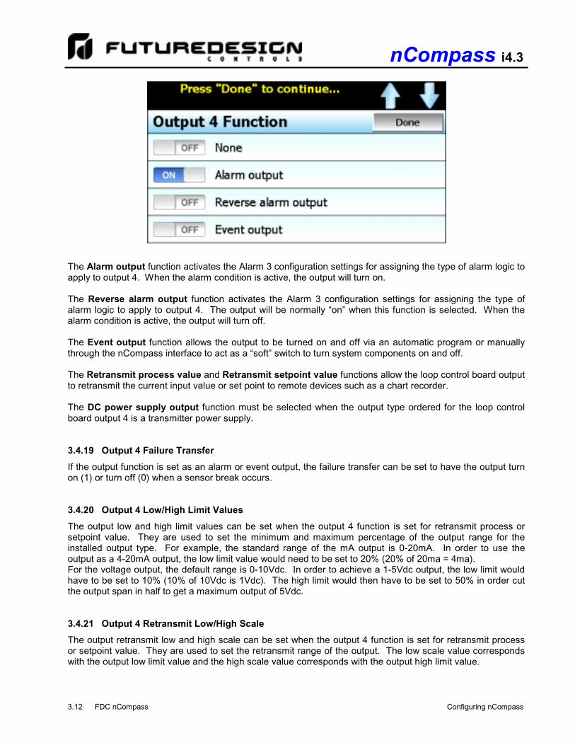
The Output 4 Function selection allows the OEM to configure the loop control board output as an alarm, event or retransmit output. The output selections are mutually exclusive, i.e., selecting one will turn off the others. Once the desired function has been selected, press the “Done” button to set the output function and return to the main Loop Setup screen. NOTE: The output function must be set to match the type of output ordered on the loop control board.
Relay, triac and SSR output types are used for alarm or event outputs. The retransmission Vdc and mA output types are used for process value or set point retransmit.
nCompass i4.3
3.12 FDC nCompass Configuring nCompass
The Alarm output function activates the Alarm 3 configuration settings for assigning the type of alarm logic to apply to output 4. When the alarm condition is active, the output will turn on. The Reverse alarm output function activates the Alarm 3 configuration settings for assigning the type of alarm logic to apply to output 4. The output will be normally “on” when this function is selected. When the alarm condition is active, the output will turn off. The Event output function allows the output to be turned on and off via an automatic program or manually through the nCompass interface to act as a “soft” switch to turn system components on and off. The Retransmit process value and Retransmit setpoint value functions allow the loop control board output to retransmit the current input value or set point to remote devices such as a chart recorder. The DC power supply output function must be selected when the output type ordered for the loop control board output 4 is a transmitter power supply. 3.4.19 Output 4 Failure Transfer
If the output function is set as an alarm or event output, the failure transfer can be set to have the output turn on (1) or turn off (0) when a sensor break occurs. 3.4.20 Output 4 Low/High Limit Values
The output low and high limit values can be set when the output 4 function is set for retransmit process or setpoint value. They are used to set the minimum and maximum percentage of the output range for the installed output type. For example, the standard range of the mA output is 0-20mA. In order to use the output as a 4-20mA output, the low limit value would need to be set to 20% (20% of 20ma = 4ma). For the voltage output, the default range is 0-10Vdc. In order to achieve a 1-5Vdc output, the low limit would have to be set to 10% (10% of 10Vdc is 1Vdc). The high limit would then have to be set to 50% in order cut the output span in half to get a maximum output of 5Vdc. 3.4.21 Output 4 Retransmit Low/High Scale
The output retransmit low and high scale can be set when the output 4 function is set for retransmit process or setpoint value. They are used to set the retransmit range of the output. The low scale value corresponds with the output low limit value and the high scale value corresponds with the output high limit value.

nCompass i4.3
Configuring nCompass FDC nCompass 3.13
3.4.22 Alarm (1-3) Function
The Alarm 1, 2 and 3 Functions are used to select the alarm type for outputs 2, 3 and 4 respectively if the output is configured as an alarm or reverse alarm. The alarm selections are mutually exclusive, i.e., selecting one will turn off the others. Once the desired alarm type has been selected, press the “Done” button to set the alarm function for the loop control board output and return to the main Loop Setup screen.
NOTE: For the following alarm descriptions, SV = the control set point value, ASP is the alarm set point and
AHY is the alarm hysteresis. A Process high alarm is independent of set point. When the process value is higher than the alarm set point, a process high alarm occurs. When the process value is lower than the alarm set point minus the alarm hysteresis, the alarm is off. A Process low alarm is independent of set point. When the process value is lower than the alarm set point, a process low alarm occurs. When the process value is above the alarm set point plus the alarm hysteresis, the alarm is off. A Deviation high alarm is dependant upon the control set point and alerts the operator when the process value deviates too high over the set point value. When the process is higher than SV+ASP (note that the alarm set point is entered as a positive value), a deviation high alarm occurs. When the process falls below SV+ASP-AHY, the alarm is off. A Deviation low alarm is dependant upon the control set point and alerts the operator when the process deviates too far below the set point value. When the process is lower than SV+ASP (note that the alarm set point is entered as a negative value), a deviation low alarm occurs. When the process is higher than SV+ASP+AHY, the alarm is off. A Deviation band high/low alarm sets two trigger levels relative to the control set point value. The two trigger levels are SV+ASP and SV-ASP for the high and low alarm values. When the process value is higher than SV+ASP or lower than SV-ASP, a deviation band alarm occurs. When the process value is within the trigger levels, SV+ASP-AHY and SV-ASP+AHY, the deviation band alarm is off. An End of automated program alarm is not associated with the process value or set point. The alarm is turned on upon completion of an automatic ramp/soak program. The alarm will turn off when another program is started, when power is cycled to the loop control board or when the “Reset” button is pressed on the Alarm screen of the runtime application.

nCompass i4.3
3.14 FDC nCompass Configuring nCompass
The Hold mode alarm is not associated with the process value or set point. The alarm is turned on when the running program is in hold. The alarm will turn off when the program is placed back into run or the program is stopped. Note that this “alarm” is not indicated on the nCompass interface. The Static mode alarm is not associated with the process value or set point. The alarm is turned on when the loop control is in the single set point (static) mode of operation. The alarm will turn off when the loop control is running an automatic program. Note that this “alarm” is not indicated on the nCompass interface. The Holdback mode alarm is not associated with the process value or set point. The alarm is turned on when the running program is in holdback. The alarm will turn off when the holdback condition has been met or the program is stopped. Note that this “alarm” is not indicated on the nCompass interface. 3.4.23 Alarm (1-3) Mode
The Alarm 1, 2 and 3 Modes are used to select the mode of operation for outputs 2, 3 and 4 respectively if the output is configured as an alarm or reverse alarm. The mode selections are mutually exclusive, i.e., selecting one will turn off the others. Once the desired alarm mode has been selected, press the “Done” button to set the alarm operation for the loop control board output and return to the main Loop Setup screen.
Normal alarm action has the alarm output off in the non-alarm condition and on in the alarm condition. The output state is inverted for a reverse alarm output. Latching alarm action will keep the alarm output on even if the alarm condition has cleared until the alarm is reset by the user. The output state is inverted for a reverse alarm output. Hold alarm action prevents the alarm from activating on power up even when an alarm condition is present. The alarm will be blocked until the alarm condition clears. Once cleared, the alarm will then operate normally and activate when an alarm condition occurs. The Latching and hold alarm action combines both the latching and hold alarm actions listed above.

nCompass i4.3
Configuring nCompass FDC nCompass 3.15
3.4.24 Alarm (1-3) Indication
The Alarm 1, 2 and 3 Indication settings are used to select whether the alarm will be shown in the nCompass runtime application or be hidden from the user. This allows the OEM to configure an alarm to perform a specific control function while preventing the user from adjusting the set point or seeing the activation state of the alarm.
When the alarm indication is set for Hide alarm status/settings, the alarm will be removed from the nCompass runtime application. The user will not be able to edit the alarm message or adjust the alarm set point. When the alarm activates, there will be no indication or message on the alarm screen and the audible alarm will not sound. The alarm operates as a “silent” alarm with no indication to the user. When the alarm indication is set for Show alarm status/settings, the user will be able to access and change the alarm set point and alarm message under the device settings. When the alarm occurs, the alarm message will be displayed on the Alarm screen and the audible alarm will sound. The indication selections are mutually exclusive, i.e., selecting one will turn off the other. Once the desired alarm indication has been selected, press the “Done” button to set the alarm operation and return to the main Loop Setup screen. 3.4.25 Alarm (1-3) Setpoint
The alarm set points can be set when the alarm function is set for a process or deviation type of alarm. If the alarm indication is set to “show” the alarm status and settings, the set point will also be available in the nCompass runtime under device settings for user edit. If the alarm indication is set for “hide” alarm status and settings, the alarm set point will not be available in the nCompass runtime and can only be changed via the loop setup in the Configurator. 3.4.26 Alarm (1-3) Hysteresis
The alarm hysteresis can be set when the alarm function is set for a process or deviation type of alarm. It is used to eliminate rapid on/off cycling of the alarm output by applying a safe-sided dead band to the alarm. When the alarm set point is exceeded, the alarm will activate. The alarm will not deactivate until the process rises above (for low alarm) or falls below (for high alarm) the alarm set point by the hysteresis value. The hysteresis can be set from a minimum of 0.1 to a maximum of 50.0 for units of degrees Centigrade and to a maximum of 90.0 for units of degrees Fahrenheit and process units.

nCompass i4.3
3.16 FDC nCompass Configuring nCompass
3.4.27 Setpoint at Start of Automatic Program
The Setpoint at Start of Automatic Program selection is used to select the set point that will be used by the loop control at the start of a program. The start set point selections are mutually exclusive, i.e., selecting one will turn off the others. Once the desired starting set point has been selected, press the “Done” button to return to the main Loop Setup screen. NOTE: If nCompass is set for dual loop operation, it is recommended that both loop control boards be set
to the same selection so that both loop controls start an automatic ramp/soak program in the same manner to avoid operator confusion.
The Current process value selection will use the current process value as the control set point when a program is started. The Current control setpoint selection will use the current (static) set point as the control set point when the program is started. Note that the P-Series control provides a selection for using the start set point value of a program. This selection is not supported by nCompass and can not be configured or entered for an automatic program in the nCompass runtime application. Only the current PV or control SP selections are supported. The normal method is to start from the process value, because this will produce a smooth and bumpless start to the process. However, if the time period of the first step must be defined, using the current control set point for the starting point will insure that the first step time duration is maintained. 3.4.28 Setpoint at End of Automatic Program
The Setpoint at End of Automatic Program selection is used to select the set point that will be used by the loop control at the end of a program. The end set point selections are mutually exclusive, i.e., selecting one will turn off the others. Once the desired end set point has been selected, press the “Done” button to return to the main Loop Setup screen. NOTE: If nCompass is set for dual loop operation, both loop control boards must be set to the same
selection so that both loop controls end the program in the same manner or a program run error will occur. When the final set point is used, the program remains in operation on the end step with the final set point value while the program ends when the current control set point is used. If one loop ends while the other remains running in the end step, the automated program run error will occur.

nCompass i4.3
Configuring nCompass FDC nCompass 3.17
The Final setpoint of automatic program selection will use the final set point value programmed on the end step of the program as the control set point when the program reaches the end step. When this mode is selected, the program will remain active once the “End” step is reached in order to hold the loop set point at the set point entered on the end step. However, any outputs programmed as events will turn off and remain off until the user selects program “Halt” in order to turn off the program and return to static (single set point) operation. The event outputs will then be operational again. If event outputs are required to be on in order for the system to operate, the “Current control setpoint” selection should be used. The Current control setpoint selection will use the current (static) set point (prior to the program being started) as the control set point when the program ends. When this mode is selected, the set point entry for the “End” step of the program entry will be hidden as it is not used. Any outputs configured as events will then return to their static setting (on/off state prior to the program being started). NOTE: nCompass does not support the P41/B42 “all outputs off” end of program function”. This selection
is not available through the nCompass configuration. 3.4.29 Power Fail Recovery
The Power Fail Recovery is used to select the desired mode of operation of the loop control board when power is restored if an automated program was running at the time power was lost. The recovery selections are mutually exclusive, i.e., selecting one will turn off the others. Once the desired recovery mode has been selected, press the “Done” button to set the power recovery mode for the loop control board and return to the main Loop Setup screen. IMPORTANT: If nCompass is set for dual loop operation, both loop control boards must be set to the same
recovery setting. If the recovery mode for both loop control boards is not identical, program operation of one loop may continue while the other is terminated which will cause a program run error alarm to occur as well as result in incorrect operation of the program.

nCompass i4.3
3.18 FDC nCompass Configuring nCompass
The Continue automated program from last SP selection will resume the program from where it left off with the last set point set by the program at the time of power failure. The Continue automated program from PV selection will resume the program using the current process value at the time power is restored as the set point. The Static mode selection will terminate the automated program and return the loop control to the single set point mode of operation using the previous set point value prior to starting the automated program. In addition, any outputs configured as events will also be returned to their previous on/off state that they were previously set to prior to starting the program. NOTE: nCompass does not support the P41/B42 “Of Mode” recovery option. This selection is not available
through the nCompass configuration. 3.4.29.1 Enabling Holdback For single loop systems, holdback is enabled under program entry of the nCompass runtime application. The user is then able to select the desired hold type for each program step. For dual loop systems, holdback operation is conditional based on the configuration of the loop controls. Since each loop control is running an instance of the program, they must be interlocked so that if one loop goes into hold, the other loop is placed in hold also so that they do not get out of sync with each other. Each loop of a dual loop system can have holdback enabled independently of the other loop. To enable holdback for a control loop, one of the outputs of the control loop (relay output type only) must be configured as an alarm output programmed as a “holdback mode alarm output”. The other loop control must then have its event input function programmed for “hold mode”. The output of the holdback loop must then be wired to the event input of the other loop. If the control loop enters holdback during program operation, its holdback mode alarm output will activate and turn on the event input of the other loop placing it in hold. This will keep the program of each control loop synchronized.

nCompass i4.3
Configuring nCompass FDC nCompass 3.19
In order to enable holdback for both control loops of a dual loop system, each loop must have one output programmed as a holdback mode alarm (relay output type only) and its event input function set for hold mode. External DPDT (double-pole, double-throw) relays are required to properly wire the alarm outputs to event inputs as shown below.
The relays are required to insure that the loops properly enter hold mode if the other loop is in the holdback condition since it is possible for both loops to be in holdback at the same time. Holdback takes precedence over the normal hold mode. If one loop were to come out of holdback while the other is still in holdback, it would not enter hold mode because the hold input had already been triggered. By using the external relay, when the loop exits its holdback condition, its hold input will be triggered if the other loop is still in holdback, thus allowing it to enter the hold condition and continue waiting for the other loop to have its holdback condition satisfied.

nCompass i4.3
3.20 FDC nCompass Configuring nCompass
3.4.30 Loop Communication Mode
The loop Communication Mode selection is available for loop control versions V.28 and later. The loop control boards are set to the normal communication mode by default. The mode selections are mutually exclusive, i.e., selecting one will turn off the other. Once the desired communication mode has been selected, press the “Done” button to set the communication mode of operation for the loop control board and return to the main Loop Setup screen.
The Normal communication mode selection allows the control board to operate independently of the nCompass HMI. This means that if the HMI to control board communications fail (broken wire or become disconnected), the loop control board will continue to operate under its last given set point or continue running its automatic program until completion. The HMI to control board communications can then be restored without interrupting the process. The Safety communication mode selection enables a watchdog in the loop control board which checks to insure that communications are active with the nCompass HMI. If communications fail (broken wire or become disconnected), the loop control board will turn off its outputs until communications are restored. This affects operation in two ways. First, upon power up, the loop control outputs will remain off until the nCompass HMI boots up and enters the runtime application. Once the HMI begins operation and starts communicating with the loop control boards, their outputs will be enabled. This prevents the loop control boards from affecting the process until the user has the ability to enter set points, turn events on/off, etc. Second, if a communications failure does occur, the loop control boards will turn their outputs off after a one minute delay, in affect stopping the process, until communications are restored. Since the operator has no way of turning off events or changing set points without a functioning user interface, this provides a way of automatically turning off the process. . NOTE: When the safety communication mode is used, all loop control board outputs are disabled when
communications are missing regardless of the configured mode of operation for the output. This includes, control, alarm, event, etc.

nCompass i4.3
Configuring nCompass FDC nCompass 3.21
3.5 Calibration
Each nCompass loop control is calibrated at the factory before shipment; however, they can be recalibrated in the field with the use of proper calibration equipment. While the basic calibration of the unit is highly stable and set for life, the Loop 1 and Loop 2 Input offset calibration provides the means to offset the permanent factory calibration. Typically reasons for applying this offset may include the need to match a particular reference standard, to match the calibration to a particular transducer or sensor or to remove long term drift in the factory set calibration. The input offset calibration provides a two point offset; a low point offset and a high point offset. The two point offset constructs a straight line (linear calibration) between the two points. To insure greatest accuracy, it is best to calibrate with the two points at the minimum and maximum operating ranges of the system.
To begin calibration, send the low signal input to the loop input. If the process value does not match the reference signal, adjust the low point offset so that the process value matches the reference input signal. Press the button to switch to the high point offset and then apply the high signal input to the loop control. Adjust the high point offset if necessary in order to make the process value match the reference signal. IMPORTANT: After a user calibration has been performed, a calibration error may occur if the input type of
the loop control is later changed to a different type. Should this occur, a user calibration must be performed for the newly selected input type.

nCompass i4.3
3.22 FDC nCompass Configuring nCompass
3.6 Functions
The nCompass functions are accessed from the “Startup” menu and allow the OEM to select which screens/menu items will be enabled (shown) in the nCompass runtime application. These functions can be used to customize the system to meet specific requirements.
When functions are disabled at the configurator level from the Functions list, it will be disabled in the runtime software by removing the menu item or disabling the field so the operator can not select the function or edit any corresponding settings related to the function. The following list shows the available nCompass functions, where to find the menu item(s) applicable to the function and a description of what it applies to. IMPORTANT: Disabling nCompass functions that are not required for the application results in a system
that is clean and easy to use for the operator; however, be careful when disabling certain items. Without access to them, there will be no way of determining if the system is operating as required.
Orion Function Runtime Menu Location Description
Single View View\Single View loop PV, %Out, set loop auto tune, manual output mode and loop set point NOTE: Without access to the single loop view screen, the user will be unable to initiate auto tune or set loop in manual mode and adjust its output.
Dual View View\Dual view loop PV, %Out, set loop set point NOTE: Without access to at least one loop view screen, the user will be unable to manually adjust loop set points.
Chart View View\Chart view and set up real time trends for loops and monitors
Event Control View\Event view and enable or disable manual events NOTE: Without event screen access, user will be unable to manually turn events on/off which could prevent them from operating equipment if events are used to do so.

nCompass i4.3
Configuring nCompass FDC nCompass 3.23
Orion Function Runtime Menu Location Description
Alarm View View\Alarm Notifications
view and reset current alarms current alarm status NOTE: With the function disabled, the user will only be able to access the alarm screen to reset an alarm when the alarm occurs by pressing the flashing alarm icon. If the alarm is latching and does not reset, the user will be unable to return to the screen to try and clear the alarm unless another alarm occurs to again display the flashing alarm icon.
Alarm Log View\Alarm Log view and email alarm history files
Security Settings Security Notifications
view/set security rights, view audit trails, user log on view security and audit status NOTE: If security is enabled, but system security is then disabled through this item, the user will be unable to log on. Default security (operator level) access will be used. This allows audit trails to be active while hiding all user security features. With security menu disabled, audit trail files are accessible via Log/USB File Utilities or temporarily re-enable security menu to gain access to the audit files.
Automatic Program Control/Recovery
Program Device\Settings\Offline\Set\Recovery Notifications
view, create, edit and run automatic ramp/soak programs set power recovery mode view program status NOTE: When disabled, all program items and menus will be removed from the runtime application. The user will be unable to access or start programs via the interface.
Automatic Program Holdback Entry
Program\Entry access to enter holdback setpoint and program holdback type for a step
Automatic Program Jump Entry
Program\Entry\Step Data access to program jump step type in an automatic program
Data Logging Data\Data Notifications
enable/disable data logging, select points for logging, access to historical viewer, FTP and USB File utilities view data log status, length and interval NOTE: If data logging is set to log on program operation or when nCompass starts and this menu is then disabled, data logging will be disabled. This menu item must remain visible in order for the built in data logging of nCompass to function. The USB File utilities will not be accessible to copy or delete data, alarm, audit or program files. Alarm, audit and data files may be transferred via FTP if unit is so configured.
Data Log Viewer Data\Chart access to view historical data log files
Annotations Data\View\Annotation access to add and view operator annotations to data files
nCompass i4.3
3.24 FDC nCompass Configuring nCompass
Orion Function Runtime Menu Location Description
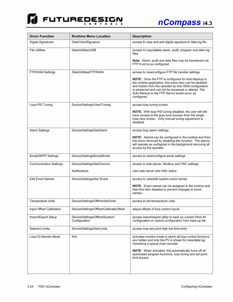
Digital Signatures Data\View\Signature access to view and add digital signature to data log file
File Utilities Data\Utilities\USB access to copy/delete alarm, audit, program and data log files Note: Alarm, audit and data files may be transferred via FTP if unit is so configured.
FTP/WAN Settings Data\Utilities\FTP/WAN access to view/configure FTP file transfer settings NOTE: Once the FTP is configured for Auto Backup in the runtime application, this menu item can be disabled and hidden from the operator so that OEM configuration is preserved and can not be accessed or altered. The Auto Backup to the FTP Server would occur as configured.
Loop PID Tuning Device\Settings\View\Tuning access loop tuning screen NOTE: With loop PID tuning disabled, the user will still have access to the auto tune function from the single loop view screen. Only manual tuning adjustment is disabled.
Alarm Settings Device\Settings\Set\Alarm access loop alarm settings NOTE: Alarms can be configured in the runtime and then the menu removed by disabling this function. The alarms will operate as configured in the background removing all access by the operator.
Email/SMTP Settings Device\Settings\Email\Email access to view/configure email settings
Communication Settings Device\Settings\Set\Comms Notifications
access to web server, Modbus and VNC settings view web server and VNC status
Edit Event Names Device\Settings\Set \Event access to view/edit system event names NOTE: Event names can be assigned in the runtime and then this item disabled to prevent changes to event names.
Temperature Units Device\Settings\Offline\Set\Units access to set temperature units
Input Offset Calibration Device\Settings\Offline\Calibrate\Offset adjust offsets of loop control inputs
Import/Export Setup Device\Settings\Offline\System\ Configuration
access import/export utility to back up current Orion-M configuration or restore configuration from back-up file
Setpoint Limits
Device\Settings\Set\Limits
access loop set point high low limit entry
Loop1/2 Monitor Mode
N/A activates monitor mode in which all loop control functions are hidden and only the PV is shown for view/data log mimicking a typical chart recorder NOTE: When activated, this automatically turns off all automated program functions, loop tuning and set point limit access.

nCompass i4.3
Configuring nCompass FDC nCompass 3.25
Orion Function Runtime Menu Location Description
Loop2 Only Monitor Mode
N/A activates monitor mode for loop 2 only in which all loop 2 control functions are hidden and only the PV is shown for view/data log. Loop 2 is also removed from automatic program functions.
Language
Device\Settings\Offline\Set\Language
access to set the nCompass display language selections for menus and online help
Timer
View\Single activates the event 1 timer function NOTE: This function requires V.28 and later loop control boards. The communication safety mode of operation is required to enable this feature.
3.7 Startup View
The “Startup View” screen is accessed from the “Startup” menu and allows the OEM to define which of the main view screens the runtime application will show when it first starts and when the “Home” icon is pressed.
The available selections are Single loop View, Dual loop View, Chart View, Event Control, Alarm View and Alarm Log. NOTE: If the selected screen to view on startup is disabled in the nCompass functions list, the screen will
only be available when the “Home” icon is pressed.

nCompass i4.3
3.26 FDC nCompass Configuring nCompass
3.8 Alarm/Event Tagnames
To edit the alarm or event names, there must be at least one loop control board output configured as an alarm or as an event for the corresponding name screen to be accessible. The alarms and events are assigned in sequential order starting with the loop 1 outputs and then the loop 2 outputs. 3.8.1 Alarm Names
The Alarm Names screen is accessed from the Tagnames menu and allows the OEM to edit the names of all configured alarm outputs. These names will be displayed in the runtime application as the alarm description on the Alarm Monitor screen. To change the name of an alarm, select the alarm from the list and press the “Edit” button to enter the desired text up to 25 characters.
3.8.2 Event Names
The Event Names screen accessed from the Tagnames menu and allows the OEM to edit the names of all configured event outputs. These names will be displayed in the runtime application under the Event control and program step Event screens. This allows each event to be identified by the function it performs for the end user. To change the name of an event, select the event from the list and press the “Edit” button to enter the desired text up to 9 characters.

nCompass i4.3
Configuring nCompass FDC nCompass 3.27
3.9 Custom Name\Address
The ‘Custom Name\Address’ screen is accessed from the ‘Tagnames’ menu and allows the OEM to configure the main splash screen when the nCompass runtime application starts. This is used so the OEM name and contact information is shown each time the nCompass controller is powered up. It also allows the OEM to change the name of the controller to adapt it to a specific product or market.
To edit the company, address, phone number or controller (product) name, press the field and enter the desired text. Each field can be entered with a maximum of 24 characters that will be displayed on the splash screen when nCompass starts.


nCompass i4.3
APPENDIX FDC nCompass A.1
Appendix

nCompass i4.3
A.2 FDC nCompass APPENDIX
How to Order nCompass LC is ordered as 3 or 4 components dependant upon the number of control loops, one or two.
(1) Power Input 1: 11 to 36 VDC
(2) Sound Output 0: None
(3) SD Card Slot 1: Yes
(4) Ethernet 1: Yes
(5) Network 0: None
Cable: Display to B42 Control Board CA2011-8D: Cable (10ft) from Display to B42 controller.
Note: Consult factory for other lengths & options
Display Power Supply (input 100-240VAC / Output 24VDC) DIN Rail Mount: PS5R-SB24: 15W power supply (0.6A) Open Frame: PS3X-B24AFC: 15W power supply (0.6A)
Note: Either of the above will power the FDC-0450 touch screen display
USB Memory Stick UDF115-2GB: (2GB High Capacity USB Memory Stick (3VDC))
System Reset Timer GE1A-C10MA110/SR2P-06: Reset Timer and socket (DIN Rail)
Note: Timer is recommended for proper system restart due to momentary power interruptions (<500ms) which can erroneous operation.
(6) Software 0: None
(7) Enclosure 0: Standard
(8) Overlay Color B: Black Overlay
(9) Special Code N: Neutral Overlay (no name/logo)
B42 Programming Display Board B42 Display Board 300 mm cable: 3020B42-00300A-00/300 B42 Display Board 1000mm cable: 3020B42-00300A-00/1K
Printed Operators Manual Part Number (Orion-nCompass_LC_i4.3_User_Manual.pdf) FDC-Orion nCompass LC i4.3 User Manual
Printed Configuration Manual Part Number (Orion-nCompass_LC_i4.3_Config_Manual.pdf) FDC-Orion nCompass LC i4.3 Configuration Manual
Printed Communication Reference Manual Part Number (Orion-nCompass_LC_i4.3_Comm Reference.pdf) FDC-Orion nCompass LC i4.3 Communication Reference Manual
USB Cables & Accessories IStick-Panel USB Panel Mount Adapter IStick-4X-CVR USB Panel Mount Adapter-Nema4x
nCompass LC Sample Part Numbers (minimum of 3 component part numbers is required; (1) display, (2) firmware, (3) loop #1 with (4) loop #2 if required.)
(dual loop shown)
Item # Product Sample Part Number Description 1 Display FDC-0450-1011-000BN 4.3” display, LC software, 11-36 VDC power input, SD slot, Ethernet,
standard enclosure
2 LC Firmware SD-LC LC Loop Control Firmware (inserted into display SD slot)
3 Loop #1 B42-4166-11D0 90-250VAC power input, T/C or RTD input, output #1 1A Triac, output #2 1A Triac, output #3 relay, output #4 relay, comms, no display
4 Loop #2 B42-4366-11D0 90-250VAC power input, mA input, output #1 1A Triac, output #2 1A Triac, output #3 relay, output #4 relay, comms, no display
Options Power Supply PS5R-SD24 85-264VAC power input, Output 24VDC 15W (0.6A)
Cable CA2011-3D Cable from display to B42 (DB25 connector (display), twisted pair leads (B42), shielded (10ft)
Item #1 Model FDC - 0450 4.3” Color Touch Screen
FDC - 0450 -
Order Matrix # 1 2 3 4 5 6 7 8 9
1 0 1 1 0 0 0 B N
Control System Options (ordered separately as appropriate)
Item #2: Loop Control Firmware
Order Matrix # -
(Fixed characters SD-LC: SD card with LC (Loop Control) Display Configuration and SD plugged into display)
SD LC

nCompass i4.3
APPENDIX FDC nCompass A.3
(1) Power Input 4: 90-250 VAC, 47-63 HZ 5: 11-26 VAC or VDC (consult factory for availability)
(2) Signal Input (18-bit A/D) 1: Standard Input Thermocouple: J, K, T, E, B, R, S, N, L, C, P RTD: PT100 DI, PT100 JIS Voltage: 0-60mV 5: 0-10V, 0-1V, 0-5V, 1-5V 6: 0-20/4-20mA 9: Special Order
(3) Output 1 0: None 1: Relay rated 2A/240VAC (SPST) 2: SSR Driver 5 VDC @ 30 Ma 3: 4-20mA / 0-20mA Isolated 4: 1-5V / 0-5V/0 - 10V Isolated 6: Triac output 1A / 240VAC,SSR C: SSR Driver 14 VDC @ 40 Ma
(4) Output 2 0: None 1: Relay rated 2A/240VAC (SPST) 2: SSR Driver 5 VDC @ 30 Ma 3: 4-20mA / 0-20mA Isolated 4: 1-5V / 0-5V/0-10V Isolated 6: Triac output 1A / 240VAC,SSR 7: Transmitter power supply 20 VDC/25 ma Isolated 8: Transmitter power supply 12 VDC/40 ma Isolated A: Transmitter power supply 5 VDC/80 ma Isolated C: SSR Driver 14 VDC @ 40 Ma
(5) Output 3 0: None 1: Relay rated 2A/240VAC (SPST) 2: SSR Driver 5 VDC @ 30 Ma 6: Triac output 1A / 240VAC,SSR 7: Transmitter power supply 20 VDC/25 ma Isolated 8: Transmitter power supply 12VDC/40 ma Isolated A: Transmitter power supply 5VDC/80 ma Isolated C: SSR Driver 14 VDC @ 40 Ma
(6) Output 4 0: None 1: Relay rated 2A/240VAC (SPST) 2: SSR Driver 5 VDC @ 30 Ma 3. Retransmission 4-20 / 0-20mA, isolated 4. Retransmission 1-5 / 0-5 / 0-10VDC, isolated 6: Triac output 1A / 240VAC,SSR 7: Transmitter power supply 20 VDC/25 ma Isolated 8: Transmitter power supply 12VDC/40 ma Isolated A: Transmitter power supply 5VDC/80 ma Isolated C: SSR Driver 14 VDC @ 40 Ma
(7) Output 5 D: RS-485 Modbus RTU interface Isolated
(8) Display Board and cable 0: None 3: Display Board with 300mm connection cable 4: Display Board with 1000mm connection cable
(9) Modbus Addressing: (if blank factory default is Modbus address #1) CA: Modbus Comm Address #1 CB: Modbus Comm Address #2 CC: Modbus Comm Address #3
Note that field configuration of Comm address requires the optional display.
Item #3: B42 Loop Control Board - Loop 1
B42 -
Order Matrix # 1 2 3 4 5 6 7 8 9
D
Item #4: B42 Loop Control Board - Loop 2
B42 -
Order Matrix # 1 2 3 4 5 6 7 8 9
D

nCompass i4.3
A.4 FDC nCompass APPENDIX
FDC-nCompass Series Graphic User Interface (GUI) touch screen provides a full SCADA feature set providing ease of use with either an icon menu system with finger navigation or traditional Menu bar, data acquisition, alarm manager, operator audit trail, multi-level security with user rights, LAN connections and more. The GUI provides ease of configuration, use & support. - System Configuration for loop, alarm, input & outputs assignment,
Help language selection and more, all without an external device or PC.
- Loop Views: view 1 or 2 controls in single or dual view as well as in a Trend format (trend up to loop controls PV, SP & Percent Out).
- Profile: Virtually unlimited number of profiles with each profile having up to 64 steps with up to 6 events (3 per loop). - File Management: View, print, copy/move Profile, Alarm, Historical Data (data log files) and operator audit trial files.
File transfer via LAN features or USB flash memory. - LAN: Remote Access & touch screen operation (VNC), email/SMS
on alarm, email historical, alarm & audit trail files on-demand, Web Page (view only) and FTP of alarm, audit and historical data files automatically or on-demand.
Data Acquisition: - Data log PV, SP and PID Percent output for 1 or 2 loop controls. - Log interval: configurable 6 seconds to 31 minutes with configurable
number of days to auto start & name next file (1 to 31 days). - File Start/Stop: Configurable; operator on-demand, on system boot,
profile ramp-soak start/end or digital inputs - File Interval: Once started a data log file is configurable to auto end
and start new file with the same name as previous file with an appended time/date name. Configurable time interval is from 1 to 31 days.
- File name: Operator entered file name, batch & lot number or if running a profile, file name same as profile name. (all file names appended with date-time to file name)
- Operator Comments/Events: Unlimited operator comments/events linked to each file entered manually or via Bar Code Scanner.
- Digital Signatures: full support for user based digital signatures for each data file (data encryption).
- Historical Data File: View & print the data directly from the display (auto scale on X & Y axis with each channel selectable for right or left axis values), from a PC after data is copied/moved via LAN (FTP or email) or USB Flash Memory card provided.
B42 Loop Control: http://www.futuredesigncontrols.com/B42.HTM - Analog Input: 200ms scan rate with 18-bit A/D resolution providing high
accuracy and PID control performance - Outputs: Maximum of 4 control or auxiliary outputs - PID Control Outputs: up to 2 with Auto Tune capability (heat-cool)
Relay, SSR driver 5V, SSR driver 14V, 1A SSR, mA* or VDC* - Alarm or Event: up to 3 outputs (outputs #2, #3 & #4)
Relay, SSR driver 5V, SSR driver 14V or 1A SSR - Auxiliary Outputs: up to 2 outputs, one or two Transmitter power
supplies and/or one Retransmission* output *Note: Analog mA and VDC PID and retransmit outputs are 15-bit, contributing to high performance PID control and highly accurate retransmitted PV or SP values.
- Alarm Types: Process, Deviation and Deviation Band, all High or Low - PID Parameters: Two sets of PID values may be configured and
selected by Profile Step and/or by digital event input. (see next) - Event Inputs: Configurable for one of the following functions.
- Profile Run (momentary) - Profile Hold (closed profile hold, open profile run) - Profile Run/Hold (closed profile run, open profile hold) - Profile Abort (momentary) - Segment Advance (momentary) - PID: change from PID#1 to PID#2 (open PID#1, closed PID#2) - Manual Mode (closed manual mode, open normal control) - Failure Transfer: (closed failure transfer, open normal control)
(transfer active %Out is a pre-configured value for each output)
Profile Ramp/Soak: - Profiles: Virtually an unlimited number of profiles in system memory - Profile Type: System configurable for separate profiles per loop or
common profile time base for two loop controls. - Profile Start: via touch screen or via Event input (see above). - Profile Name: Free form 16 character (max) naming convention with
auto append time/date stamp. - Global Profile Configuration
- Profile Time Base: Time Ramp (hh:mm or mm:ss) Ramp Rate (degrees/minute or hour)
- Starting and Ending SP values (may be individually active or not). - Guaranteed Soak & Ramp (GS): - Range 1 to 999F (555C), configurable per step as low, high, band or inactive (disable). - Dual Loop: For both loops to enter GS hold as a result of one entering an active GS band, one or both loops must configure an output as “Holdback Mode Alarm” which will activate when the initiating loop enters GS as configured. This output must be wired to the other loop’s DI w/the target DI configured as profile hold.
- Power Fail / Recovery when Profile is active: - Continue from last SP value. - Continue from last PV value. - Static mode (abort profile) with last static SP entered.
- Profile Segments: (maximum of 64) - Jump To Segment: configurable by segment (also nested looping) - Events: up to 3 events* per segment. - Guaranteed Soak & Ramp: Configurable active or not by segment.
* Note: The number of events available is predicated on the control board hardware, number of control boards and configuration.
- Event Input: (profile specific; refer to B42 Control Board for all options)
- Configurable functions below (mutually exclusive to each other) - Profile Run (momentary) - Profile Hold (closed profile hold, open profile run) - Profile Run/Hold (closed profile run, open profile hold) - Step Advance (momentary) - Profile Abort (momentary) - PID Selection: select PID #1 or PID#2
Although the Event Input provides a manner to control Profile functions remotely, typically Profile actions would have the Operator using the intuitive easy to use 4.3” color touch screen (operator interface). Power Capacity Required (Watts) - A base system requires ~10 watts of 24Vdc power for the nCompass user interface. The 15W power supplies offered are sufficient to power display only. Note: The power supply should be used to power nCompass components only and not OEM or other end user components or devices. RoHS Compliant
NOTES: SCADA (Supervisory Control & Data Acquisition)
NOTES: B42 Control Board (1 or 2 may be used) NOTES: Power Supply – Optional
NOTES: Profile Ramp / Soak Specifications
P.O. Box 1196 Bridgeview, IL 60455 888.751.5444 Sales 888.307.8014 Fax
Technical Support: 866.342.5332 http://www.futuredesigncontrols.com

nCompass i4.3
APPENDIX FDC nCompass A.5
FUTURE DESIGN SOFTWARE LICENSE - For FDC nCompass Controller Future Design Controls Windows CE based nCompass display and Control Module (Idec PLC) software (listed as “SOFTWARE” in this document) is protected by copyright laws and international copyright treaties, as well as other intellectual property laws and treaties. The SOFTWARE is licensed at no charge to the end user when all components, including but not limited to the Control Module (Idec PLC components) and CE Color Touch Screen display are purchased from Future Design Controls. All ownership and rights remain with Future Design Controls. I. LICENSE GRANT. This LICENSE grants you the following rights: A. You may use Future Design’s SOFTWARE with Future Design Controls products or products marketed by Future Design Controls only. Products are considered Future Design Controls products (and products marketed by Future Design Controls) when the sale or shipment originates from our main headquarters in Bridgeview, IL or one of our authorized office locations. Products purchased from Future Design Controls distributors or OEM's with brand labels other than Future Design controls are not considered Future Design Controls products and cannot be used with Future Designs SOFTWARE. Using Future Design's SOFTWARE with any other manufacturer (or distributor) of hardware is a violation of this license and applicable copyright laws. The SOFTWARE is considered in "use" when it is installed into permanent or temporary memory (e.g. CE display unit/PLC, or other storage device) B. Solely with respect to electronic documents included with the SOFTWARE, you may make a copy (either in hardcopy or electronic form), provided that the software is not resold without the knowledge and acceptance of terms by Future Design Controls. II. TITLE; COPYRIGHT. All title and copyrights in and to the SOFTWARE (including but not limited to any images, photographs, animation, video, audio, music, text and "applets" incorporated into the SOFTWARE), the accompanying printed materials, and any copies of the SOFTWARE are owned by Future Design Controls or its suppliers. The SOFTWARE is protected by copyright laws and international treaty provisions. Therefore, you must treat the SOFTWARE like any other copyrighted material, except that you may either (A) make one copy of the SOFTWARE solely for backup or archival purposes or (B) install the SOFTWARE on each system purchased from Future Design Controls (CE display/PLC) provided you keep the original solely for backup or archival purposes. You may not copy the printed materials accompanying the SOFTWARE. III. ADDITIONAL RIGHTS AND LIMITATIONS. A. Reverse Engineering, De-compilation, and Disassembly: You may not reverse engineer, decompile, disassemble or modify the SOFTWARE (CE display software and/or Control Module (PLC) code). B. No Separation of Components. The SOFTWARE is licensed as a single product and the software programs comprising the SOFTWARE may not be separated for use on any hardware not supplied by Future Design Controls. C. Rental. You may not rent or lease the SOFTWARE. D. Software Transfer. You may NOT transfer any of your rights under this LICENSE. E. Termination. Without prejudice to any other rights, Future Design Controls may terminate this LICENSE if you fail to comply with the terms and conditions of this LICENSE. In such event, you must destroy all copies of the SOFTWARE and agree not to modify/distribute the software or download to any hardware not purchased from Future Design Controls. F. The selection, application and use of Future Design products and/or software is the sole responsibility of the purchaser or end user. No claims will be allowed for any damages or losses, whether direct, indirect, incidental, special or consequential. In addition, Future Design reserves the right to make changes without notification to purchaser or user to materials or processing that do not affect compliance with any applicable specification. Future Design Controls makes no warranties when using Future Design Controls SOFTWARE system.

nCompass i4.3
A.6 FDC nCompass APPENDIX
Software Usage Note: The selection, application and use of Future Design Control products or software is the sole responsibility of the purchaser or end user. No claims will be allowed for any damages or losses, whether direct, indirect, incidental, special or consequential. In addition, Future Design reserves the right to make changes without notification to purchaser or user to materials or processing that do not affect compliance with any applicable specification. Future Design makes no warranties when using the nCompass system. Warranty: Future Design Controls products described in this book are warranted to be free from functional defects in material and workmanship at the time the products shipped from Future Design Controls facilities and to conform at that time to the specifications set forth in the relevant Future Design Controls manual, sheet or sheets for a period of one year after delivery to the first purchaser. Future Design Controls FDC-0450 products are warranted to be free from functional defects in materials and workmanship at the time the products shipped from Future Design Controls facilities and to conform at that time to the specifications set forth in the relevant Future Design Controls manual, sheet or sheets for a period of one year after delivery to the first purchaser for use. There are no expressed or implied Warranties extending beyond the Warranties herein and above set forth. Limitations: Future Design Controls provides no warranty or representations of any sort regarding the fitness of use or application of its products by the purchaser. Users are responsible for the selection, suitability of the products for their application or use of Future Design Controls products. Future Design Controls shall not be liable for any damages or losses, whether direct, indirect, incidental, special, consequential or any other damages, costs or expenses excepting only the cost or expense of repair or replacement of Future Design Control products as described below. Future Design Controls sole responsibility under the warranty, at Future Design Controls option, is limited to replacement or repair, free of charge, or refund of purchase price within the warranty period specified. This warranty does not apply to damage resulting from transportation, alteration, misuse or abuse. Future Design Controls reserves the right to make changes without notification to purchaser to materials or processing that do not affect compliance with any applicable specifications. Return Material Authorization: Contact Future Design Controls for Return Material Authorization Number prior to returning any product to our facility:
7524 West 98th Place – Bridgeview, IL 60455 – Phone 888.751.5444 – Fax 888.307.8014
http://www.futuredesigncontrols.com


