électronique 1- Description CONTENTS ORION Series Typical applications: 1 2 3 5 6 8 Description .......................... 1 & 2 Product dimensions ................ 10 Receiver technical characteristics .................... 6 & 7 Connection diagrams ............... 9 Transmitter and receiver associations ............................... 3 E780 E - 0607 Para. Page 4 Transmitter technical characteristics .................... 4 & 5 7 Selection guides ............. 11 & 12 Accessories ............................... 8 A radio remote control provides significant advantages: Large freedom of movement Easy to use Precise, quality manoeuvres Visibility Productivity Jay Electronique's new ORION ORION ORION ORION ORION radio remote control line is designed to satisfy the needs of a wide range of standard and industrial applications, including simple and multifunction applications. The ORION ORION ORION ORION ORION line comprises a broad range of transmitters and receivers, providing different types and numbers of functions, satisfying a variety of requirements. This product line also incorporates numerous features and significant technological breakthroughs: European frequency band of 433-434 MHz with 18 possible frequencies FM radio link Simultaneous commands Programming of different functions by jumpers in receiver, or using buttons on transmitter, thus enabling numerous possibilities: - programming of identity code, - association of transmitter(s) / receiver(s), - association of transmitter button(s) / receiver(s) relays, - programming of operating mode, - programming of command interlocking functions, - programming of radiofrequency channel (on certain models), - programming of "dead man function" time (on certain models). compact, light-weight, watertight and sturdy transmitters and receivers. mechanical protection for buttons "on/off" button (on some models) Compliance with European directives: - Machinery - Hertzian equipment and telecommunication terminals (low voltage, EM compatibility, radiofrequency spectrum) ART conformity certificate Industrial equipment Cardboard box folding and gluing machines Packaging machines Wrapping machines Dynamic storage Conveyors Ovens Book stitching machines Machine control in stepped mode Industrial lifting Small lifting equipment (hoists, winches) Lift tables Industrial vehicles Milk transport Recovery vehicles Impoundment vehicles Clean-up vehicles Vehicle carriers Tailgates Skips Winches Farm equipment Wine making pumps Liquid manure tanks Fruit grading machines Sprinkling systems Debarking machines Logging equipment Mangers and livestock feeding equipment Building industry equipment Freight elevators Concrete mats Concrete plants Hoppers Quarry conveyors Asphalt spreader Infrastructure equipment Automatic industrial doors Industrial gates Industrial drop gates Staging equipment Signalling Industrial lighting Industrial production operator calls Traffic lights on industrial site Sluice gates Industrial pressure cleaners revision04-B
A radio remote control provides significant advantages:Large freedom of movementEasy to usePrecise, quality manoeuvresVisibilityProductivity
Jay Electronique's new ORIONORIONORIONORIONORION radio remote control line is designed to satisfythe needs of a wide range of standard and industrial applications, includingsimple and multifunction applications.
The ORIONORIONORIONORIONORION line comprises a broad range of transmitters and receivers,providing different types and numbers of functions, satisfying a variety ofrequirements.
This product line also incorporates numerous features and significanttechnological breakthroughs:
European frequency band of 433-434 MHz with 18 possible frequenciesFM radio linkSimultaneous commandsProgramming of different functions by jumpers in receiver, or using buttonson transmitter, thus enabling numerous possibilities:
- programming of identity code,- association of transmitter(s) / receiver(s),- association of transmitter button(s) / receiver(s) relays,- programming of operating mode,- programming of command interlocking functions,- programming of radiofrequency channel (on certain models),- programming of "dead man function" time (on certain models).
compact, light-weight, watertight and sturdy transmitters and receivers.mechanical protection for buttons"on/off" button (on some models)
Compliance with Europeandirectives:- Machinery- Hertzian equipment and telecommunication
terminals (low voltage, EM compatibility,radiofrequency spectrum)
ART conformity certificate
Industrial equipmentCardboard box folding and gluing machinesPackaging machinesWrapping machinesDynamic storageConveyorsOvensBook stitching machinesMachine control in stepped mode
A response time compatible with most of the equipmentcontrolled.
Possibility for electrical interlocking of conflictingcommands (for example: up/down) by setting receiveroutputs to "break" state (programmable by user).
Hamming distance (minimum number of bits that differbetween 2 messages that are different) of 4.
An «On/Off» function (category B stop per EN954-1)available with transmitters equipped with «On/Off» buttonand receivers equipped with «On» relay.
A receiver passive stop function in the event of radiojamming (for a duration of around 1 second) when a buttonon the transmitter is pressed and held.
Operating reliabiltyORIONORIONORIONORIONORION Series features designed to ensure operatingreliability :
Operating modesThere are three operating modes (programmable by user):
«Continuous make contact» mode:The receiver relay remains closed so long as thecorresponding control button on the transmitter remainspressed.
«Continuous break contact» mode:The receiver relay remains open so long as thecorresponding control button on the transmitter remainspressed
«Bistable» mode:The receiver relay is closed the first time thecorresponding control button on the transmitter ispressed, and opens on the second time the control buttonis pressed.
If a system is used in continuous mode with the controlbuttons maintained pressed and the operator moving about,transmission interruptions can occur due to the dispersionand propagation of radiowaves which must be taken intoaccount in accordance with the application.
Installation of other radio systemsTo avoid any risk of extended radio jamming, be sure not toinstall or use, in the vicinity and at the same time, anyother radio system with continuous transmissions in afrequency range representing +/- 100 kHz with respect tothe product's operating frequency.
The distance between the interfering transmitter and theproduct will also impact the possibility of interferenceoccurring. Be sure to keep the interfering transmitter as faraway as possible from the product.
List of available radio channels :
The transmitters and receivers are supplied programmed in their standard configuration on channel No. 17 (434.700 MHz).
The radio channel can only be modified with transmitters equipped with an «On/Off» button.
Special features of transmittersequipped with «On/Off» button- The «On/Off button» is used to switch on and off the
transmitter, thus avoiding any unintentional actions onthe function buttons.
- This button also controls the receiver «on» relay (dependingon model), thus doubling the command interruptionfeature.
- Transmitters equipped with this button have two functionswhich can be configured by the user:
- «Dead Man» time delay function (time programmable for4, 15 or 60 minutes, or deactivation of function): if none ofthe buttons are pressed while the transmitter is on, itautomatically shuts down at the end of the programmedtime delay period. This causes the receiver relay to go tothe «relaxed» state.
- Modification of radio working frequency: The user canchoose and program a frequency among 18 radiochannels. Once the frequency has been selected, thetransmitter automatically sends a frequency changecommand to the receiver.
3ORION Series / E780 E - 0607 revision04-B
Industrial Multifunction DIN Rail Industrialsmall model
Industriallarge model
1 + "on/off"
2 + "on/off"
3 + "on/off"
4 + "on/off"
5 + "on/off"
6 +"on/off"
7 +"on/off"
8 + "on/off"
9 + "on/off"
10 + "on/off"
11 + "on/off"
12 + "on/off"
13 + "on/off"
14 + "on/off"
15 + "on/off"
16 +"on/off"
Number of functions required
ReceiverTransmitter
Standard Industrial Multifunction DIN Rail Industrialsmall model
Industriallarge model
123456789
10111213141516
Transmitter ReceiverNumber of functions required
2- Transmitter(s) and receiver(s) associations
électr oni que
électr oni que
él ectr onique
+-
él ectr oni que
+-
él ectr oni que électr onique
2.2- Association of 1 transmitter to 1 receiver,with «on/off» function:
All transmitter(s)/receiver(s) associations are possible by the user.
2.1- Association of 1 transmitter to 1 receiver,without «on/off» function: T R
2.3- Association of N transmitter(s) to M receivers:Any number of transmitters ORE can be associated to any number of receivers ORR depending on the needs of theapplication.Each relay in the ORR receivers can be associated independently to any button of a transmitter by a simple «learning»procedure.
TT....
RR....
= Optimum association of number of buttons on transmitter and number of relays available in receiver.
électr onique
T R
= Possible association
= Optimum association of number of buttons on transmitter and number of relays available in receiver. = Possible association
Charging time(supplied with accumulators)Charging temperature range (supplied with accumulators)
Sofety
Mechanical protection Built-in protected foam
Storage
1 "on/of" button (depending on model)
Supplied with batteries:same time standards or industrials transmittersSupplied with accumulators:42h for 50 % use time
< 3 h
0°C to +40°C
Case, reference : OWE13(optional accessory)
Case, reference : UBWE34(optional accessory)
1 year(for a typical use of 50 times per day
with impulses of 2 seconds)
multifunction(OREL)
ABS
yellow
IP65
160 g
4, 6, 8, 12 or 16
3 x 1,5V batteries (type AAA) or 3 x accumulators (type AAA) (4)
Operating mode Simultaneous commandsTransmission module(1) 18 frequencies per deviceTransmission frequency (1) UHF 433,100 MHz to 434,740 MHzTransmission power (1) < 1 mW (license not required) built-in antenna
Average range (2) 150 m in unobstructed area50 m in typical industrial environment
Modulation FMRadio link Momentary (when command button pressed)Identity code 256 codes programmable by microswitches on transmitter
Operating temperature range -20° C to + 50° C
Storage temperature range -30° C to + 70° C
Battery or accumulator charge level indication
2 indication levels by a red indicator light:Red ind. light off = batteries or accumulators charge is > 10%Red ind. light flashes fast = batteries must be replaced or accumulators must be recharged.
Other indication
Model without "on/off" button:a green indicator light comes on and flashes while the function button is pressed.Model with "on/off" button:A green indicator light comes on and flashes when the transmitter keypad is active.
Fastening • Carrying clip (optional accessory, see chapter 8)• Fixation support (optional accessory, see chapter 8)
3- Transmitter technical characteristics
é lec tr oniq ue
é lec tr oniq ue
+-
3.1 Characteristics common to 3 transmitter versions(standard, industrial et multifunction)
3.2 Characteristics specific to each version
(1) = Supplied programmed on channel No. 17 in standard configuration.REMINDER: The transmitters radio channel can only be changed on the ORE transmitters equipped with an «on/off» button.
(2) = The range varies according to environment conditions, the reception antenna and its position (the range is decreased in case of metal obstacles such as: metalframeworks, walls etc.)
élec tron ique
(3) = Supplied with 2 AAA batteries.(4) = Supplied with 3 AAA batteries; can be used with 3 AAA accumulators.
These transmitters, when equipped with AAA accumulators, can be recharged directly on an ORCL• charger support. The chargersupport must be ordered separately.
(ORRA)Housing material PC-GFHousing color Grey Yellow GreyDegree of protection IP 20Number of command outputs 3 or 2+1 (2) 2 or 4+1 (2) 8+1 (2) or 16+1 (2)
Maximum weight 220 g 350 g 1200 gMaximum number of transmitter function buttons (3) being able to be learned by a function relay
4
Number of relay outputs simultaneously controllable
Antenna VUB084 or antenna VUB086 (possible use of extension with support VUB105/VUB125/VUB131)
1 red indicator light
Antenna VUB084 + extension with support VUB105/VUB125/VUB131 or antenna VUB086 + extension with support VUB105/VUB125/VUB131
Operating temperature range -20°C to +50°CStorage temperature range -30°C to +70°CTuner (1) UHF 433,100 MHZ to 434,740 MHzSensitivity < 2µVIdentity code By a "learning" procedure, the receiver relays can memorize the identity codes of the associated transmitters
Protection of power supply • Against overcurrents : 1 fuse on phase (ORRS and ORRA). • Against polarity inversions in the case of 12VDC power supply.
Outputs Type of command by relay with 1 NO contact (1 NC or bistable contact possible by programming)min. / max. current 10 mA / 8A (50mA recommended)
max. voltage 250 VACresponse time 50 ms
Switching category DC13 at 0,5 A / 24 VDC - AC15 at 3 A / 250VACOperating mode Continuous or bistable (by programming jumper or microswitch)Interlocking Programmable by jumper or microswitch
Additional function 1 "on" relay (controlled by transmitter "on/off" button - depending on transmitter model),B category according to EN 954-1.
4- Receiver technical charateristics
él ect ronique
4.1 Characteristics common to 3 receiver versions(DIN rail, small and large industrial model)
4.2 Characteristics specific to each version
(1) = Supplied programmed on channel No. 17 in standard configuration.REMINDER: The transmitters radio channel can only be changed on the ORE transmitters equipped with an «on/off» button.
(2) = «On» relay (relay activated by transmitter models having a «on/off»button)(3) = Different transmitter button numbers and/or different transmitter identity codes(4) = Plug-in feature possible by BNC plug on industrial receivers, with kit OWR01(5) = Antenna integration possible in industrial receiver housings, with kit OWR02 (delivered with the receivers). Beware, the range is divided by 2 in this case.
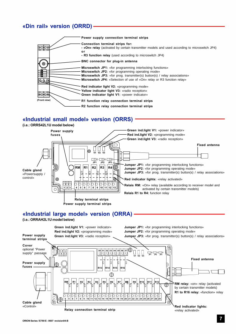
Connection terminal strips for:- «On» relay (activated by certain transmitter models and used according to microswitch JP4)or- R3 function relay (used according to microswitch JP4)
Red indicator light V2: «programming mode»
R2 function relay connection terminal strips
«Industrial small model» version (ORRS)(i.e.: ORRS42L1U model below)
«Industrial large model» version (ORRA)(i.e.: ORRAH2L1U model below)
R1 function relay connection terminal strips(Front view)
Microswitch JP4: «Selection of use of «On» relay or R3 function relay»
8 ORION Series / E780 E - 0607 revision04-B
+
ACQ ACQ ACQ ACQZ1 Z2 Z3 Z4
2 2 2 2
A B DE F G H
C
KN O
LM P1 2 45 6 7 8
3
9 10 11
14 15
12
13 16
Power supply 12/24 VDC or 230 VACDegree of protection IP 20Weight 400 g max.
Output VoltageMax. current
9 VDC300 mA
Storage temperature range -30°C to +70°CCharging temperature range 0°C to +40°C
1,70mLength of adapter cable / connector for multifunction transmitter
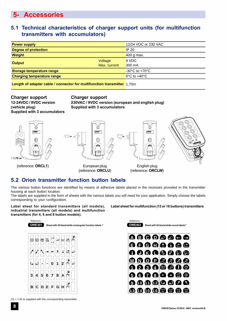
5- Accessories
électronique électronique électronique
5.1 Technical characteristics of charger support units (for multifunctiontransmitters with accumulators)
Charger support230VAC / 9VDC version (european and english plug)Supplied with 3 accumulators
Charger support12-24VDC / 9VDC version(vehicle plug)Supplied with 3 accumulators
English plug(reference: ORCLW)
European plug(reference: ORCLU)
(reference: ORCL1)
~ 1,70 m
+
+
+
+
+
+
+
+
+
5.2 Orion transmitter function button labelsThe various button functions are identified by means of adhesive labels placed in the recesses provided in the transmitterhousing at each button location.The labels are supplied in the form of sheets with the various labels you will need for your application. Simply choose the labelscorresponding to your configuration.
OWE301Reference :
Sheet with 45 black/white rectangular function labels (1) OWE403Reference :
Sheet with 64 black/white round labels(1)
Label sheet for standard transmitters (all models),industrial transmitters (all models) and multifunctiontransmitters (for 4, 6 and 8 button models).
Label sheet for multifunction (12 or 16 buttons) transmitters
+ 1 20
4 53 7 86 A
B C D E F G H
(1) = 1 kit is supplied with the corresponding transmitter
9ORION Series / E780 E - 0607 revision04-B
24 VAC
12 VDC
48 VAC
-+
1 2 3
1 2 3
1 2 3
1 2 3
ORRA•2L1A ORRA•2L1B
230 VAC
115 VAC
1 2 3
1 2 3
ORRA•2L14
24 VDC (2)
JP1
JP2
JP3
123
30313233
353637
34
V1V2V3
RM
R1
R2
R3
R4
R5
R6
R7
R8
R9
R10
R11
R12
R13
R14
R15
R16
456789
1011121314151617181920212223242526272829
F1F2
JP1
JP2
JP3
123
V1V2V3
RM
R1
R2
R3
R4
R5
R6
R7
R8
456789
1011121314151617181920212223242526272829
F1F2
R1
R2
R3
RM
R4
123
456789
10111213
V1V2V3
JP1JP2
JP3
F1F2
R1
R2
123
6789
V1V2V3
JP1JP2
JP3
F1F2
24 VDC (2)
24 VAC
12 VDC
48 VAC
-+
115 VAC
230 VAC
1 2 3
1 2 3
1 2 3
1 2 3
1 2 3
1 2 3
ORRS••L1F ORRS••L1T
ORRS••L1U
6- Connection diagrams
5
7
6
8
1
3
2
4
JP2JP3JP4
JP1OFF ON
V1 V3 V2
6.1 Connection diagram for DINrail receiver model - ORRDORRDORRDORRDORRD
6.2 Connection diagram for Industrialreceiver, small model - ORRSORRSORRSORRSORRS
6.3 Connection diagram for Industrial receiver, large model - ORRAORRAORRAORRAORRA
1-2 terminals =Power supply: see connections below
5-6 terminals = R1 function relay
7-8 terminals = R2 function relay
3-4 terminals =RM «On» relay or R3 function relay(1)
(1) = The relay function can be selected by microswitch(2) = No polarity to be respected
Power supply:see connectionsper models below
1 212/24 VDC (2) - 24 VAC
ORRS21L1• ORRS42L1•
Power supply:see connections per models below
ORRA82L1• ORRAH2L1•
10 ORION Series / E780 E - 0607 revision04-B
170
229
90
66
120
47
35
4827
100
30
4xØ4
électronique
240
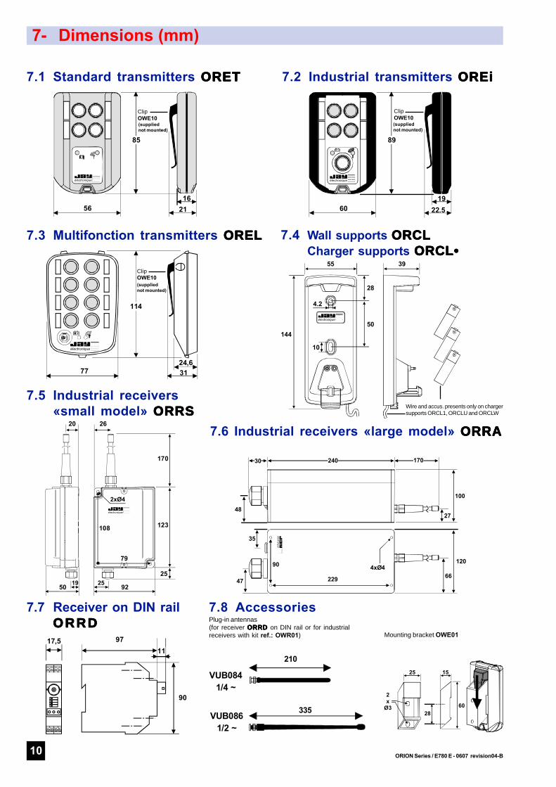
7- Dimensions (mm)
144
28
50
4.2
10
55 39
électronique
+
+
+
9711
90
17,5
19
électronique
2550
123
170
92
79
108
2xØ4
2620
25
3124,6
114
77
électronique
22.519
électronique
+ -
89
602116
électronique
85
56
7.1 Standard transmitters ORETORETORETORETORET 7.2 Industrial transmitters OREiOREiOREiOREiOREi
Wire and accus. presents only on chargersupports ORCL1, ORCLU and ORCLW
(suppliednot mounted)
210
VUB0841/4 ~
335VUB0861/2 ~
2860
1525
2x
Ø3
(suppliednot mounted)
(suppliednot mounted)
11ORION Series / E780 E - 0607 revision04-B
Reference DesignationOWE10 Carrying clip (on support ref.: OWE01, belt, pocket ...) (5)
OWE20 Neck strapOWE13 Case for standard (ORET) or industrial (OREi) transmitterUBWE34 Case for multifunction (OREL) transmitter
Reference DesignationOWE301 45 black/white rectangular function labels for standard, industrial and multifunction transmitters (4, 6 or 8 buttons) (4)
OWE403 64 black/white round labels for multifunction transmitters (12 or 16 buttons)(4)
Reference DesignationOWE01 Mounting support for standard and industrial transmitter with carrying clipORCL Mounting support for multifunction transmitter
ORCL1 12-24 VDC (vehicle connector) / 9 VDC charger support unit + 3 accumulators AAA type, for multifunction transmitters (OREL) with accumulators
ORCLU 230 VAC (european plug) / 9 VDC charger support unit + 3 accumulators AAA type, for multifunction transmitters (OREL) with accumulators
ORCLW 230 VAC (english plug) / 9 VDC charger support unit + 3 accumulators AAA type, for multifunction transmitters (OREL) with accumulators
(1) = Supplied programmed on channel No. 17 in standard configuration.REMINDER : The transmitters radio channel can only be changed on the ORE transmitters equipped with an «on/off» button.
(2) = Supplied with 2 AAA batteries.(3) = Supplied with 3 AAA batteries; can be used with 3 AAA accumulators.
These transmitters, when equipped with AAA accumulators, can be recharged directly on an ORCL• charger support. The charger supportmust be ordered separately.
électr onique
électr onique
électr onique
électr onique électr onique
+ -
électr onique
+ -
élect roniqu e
élect roniqu e
élect roniqu e
élect roniqu e
élect roniqu e
(4) = 1 kit is supplied with the corresponding transmitter.
(5) = 1 clip (not mounted) is supplied with transmitters.
VUB060 90° BNC elbow for antenna VUB084 or BNC antenna extension (3) (6)
VUB170 0,5 m extension for BNC antenna (5)
VUB105 2 m extension for BNC antenna + non insulated bracket (5)
VUB125 5 m extension for BNC antenna + non insulated bracket (5)
VUB131 10 m extension for BNC antenna + non insulated bracket (5)
électronique
8- Selection guide, references for ordering (cont.)
18.0
7.07
- re
visi
on04
-B -
E.D
echa
me
The products presented in this document are subject to change. Product descriptions and characteristics are not contractually binding.Please go to our internet site www.jay-electronique.fr to download the most recent updates to our documentation. E780 E - 0607
8.2 ORION receivers (1)
Accessories for ORION receivers:
(1) = Supplied programmed on channel No. 17 in standard configuration.REMINDER : The transmitters radio channel can only be changed on the ORE transmitters equipped with an «on/off» button.
(2) = «On» relay
(3) = BNC antenna and BNC extension to be ordered separately.(4) = 1 kit is supplied with industrial receivers.(5) = Except for the DIN rail model which comes with a BNC antenna connector as a standard feature, the other receiver models require the
plug-in antenna kit Ref.: OWR01 for use of an antenna or a plug-in antenna extension.(6) = Not suitable for direct connection to antenna Ref.: VUB086; in this case, use an intermediate extension type VUB1••
élec tron ique
élec tron ique
élec tron ique
ZAC la Bâtie, rue ChamprondF38334 SAINT ISMIER cedex +33 (0)4 76 41 44 00 - +33 (0)4 76 41 44 44
www.jay-electronique.fr
ELEKTRO-TRADING sp. z o.oTel. +48 (0-32) 734-55-72