14
Orthorectification Orthorectification using using ERDAS IMAGINE ERDAS IMAGINE
| Date post: | 30-Dec-2015 |
| Category: |
Documents |
| Upload: | albert-fowler |
| View: | 231 times |
| Download: | 0 times |

Orthorectification usingOrthorectification usingERDAS IMAGINEERDAS IMAGINE

Geometric distortions are present in satellite images caused by satellite
platform and its elliptic movement around the earth, due to the imaging
sensor (parameters like focal length, instantaneous field of view, panoramic
view, and the oblique viewing system in some cases), and due to the earth
rotation, curvature, and topographic relief etc. Therefore, it is essential to
remove all types of geometric distortions in RS imagery before using it for
feature/ information extraction.
Orthorectification – Basic Concepts Orthorectification – Basic Concepts

Orthorectification – DefinitionOrthorectification – Definition
Orthorectification is the geometric transformation of an image in which
image displacements due to sensor orientation and terrain are corrected to
the projection of a map coordinate system. The accuracy of an orthorectified
image and its assigned georeferencing information is dependent on DEM
and the quality of the sensor model. Orthorectification is the process of
reducing geometric errors inherent within photography and imagery. The
variables contributing to geometric errors include, but are not limited to:
• camera and sensor orientation• systematic error associated with the camera or sensor• topographic relief displacement• Earth curvature

It is a form of rectification that corrects for terrain displacement and can be used if there is a DEM of the study area. It is based on collinearity equations, which can be derived by using 3D GCPs.
Relief displacement is corrected by taking each pixel of a DEM and finding the equivalent position in the satellite or aerial image. A brightness value is determined for this location based on resampling of the surrounding pixels. The brightness value, elevation, and exterior orientation information are used to calculate the equivalent location in the ortho image file.
Continue…Continue…
Note: In relatively flat areas, orthorectification is not necessary, but in mountainous areas (or on aerial photographs of buildings), where a high degree of accuracy is required, orthorectification is recommended
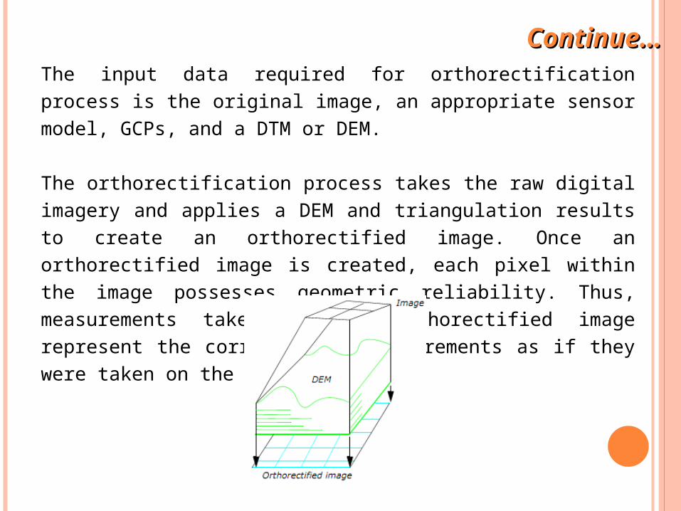
The input data required for orthorectification process is the original image, an appropriate sensor model, GCPs, and a DTM or DEM.
The orthorectification process takes the raw digital imagery and applies a DEM and triangulation results to create an orthorectified image. Once an orthorectified image is created, each pixel within the image possesses geometric reliability. Thus, measurements taken off an orthorectified image represent the corresponding measurements as if they were taken on the Earth’s surface.
Continue…Continue…

Imagery
DEM
Orthorectified Imagery
Continue…Continue…
In contrast to conventional rectification techniques, orthorectification relies on the digital elevation data, unless the terrain is flat. Various sources of elevation data exist, such as the USGS DEM and a DEM automatically created from stereo image pairs.
For different image data, different accuracy levels of DEMs are required to limit the uncertainty-related errors within a controlled limit. While the near-vertical viewing SPOT scene can use very coarse DEMs, images with large incidence angles need better elevation data such as USGS level-1 DEMs. For aerial photographs with a scale larger than 1:60000, elevation data accurate to 1 meter is recommended. The 1-meter accuracy reflects the accuracy of the Z coordinates in the DEM, not the DEM resolution or posting.
Continue…Continue…

The DEM should be large enough that the entire area to be orthorectified is covered by the extent of the DEM (excluding background). This eliminates possible conflicts between zero background value and zero data value. If the DEM is too small to completely cover the orthorectification area and has zero background values and zero data values, neither of the methods above is completely satisfactory. One way to approach the problem would be to locate and change zero data values to a very small number (0.001 for Float or Double type data, or 1 for 8-bit or16-bit data) and then recompute statistics ignoring zeros. This eliminates the effects of the background while having minimal effect on sea-level elevations.
Guidelines for DEM Selection for Ortho ResamplingGuidelines for DEM Selection for Ortho Resampling

Resampling methods used are nearest neighbor, bilinear interpolation, and cubic convolution. Generally, when the cell sizes of ortho image pixels are selected, they should be similar or larger than the cell sizes of the original image. For example, if the image was scanned 9K × 9K, one pixel would represent 0.025 mm on the image. Assuming that the SI of this photo is 1:40000, then the cell size on the ground is about 1 m. For the orthoimage, it is appropriate to choose a pixel spacing of 1 m or larger. Choosing a smaller pixel size oversamples the original image.
For SPOT Pan images, a cell size of 10 meters is appropriate. Any further enlargement from the original scene to the ortho photo does not improve the image detail. For IRS-1C images, a cell size of 6 meters is appropriate.
Continue…Continue…

In ERDAS IMAGINE, orthorectification can be done by two methods;
1. through “Image Geometric Correction” module in “Data Preparation” tool
2. through “LPS” tool
Note: We will use the first method in our exercise.

Bilinear Interpolation:
Use Bilinear interpolation when;
Selecting the correct Resampling MethodSelecting the correct Resampling Method
• the DEM covers less than the output area of the orthorectified image • the DEM cell size is approximately the same as the image cell size (for
example, a 30-meter DEM with 10-meter Spot)
Nearest Neighbor:
Use Nearest Neighbor when;
• the DEM cell size is much greater than the image cell size (for example, a 30-meter DEM with 1-meter air photo)
• the DEM covers the entire output area of the orthorectified image

Cubic Convolution:
Use Cubic Convolution when;
• the DEM cell size is much greater than the image cell size (cubic convolution is very similar to bilinear interpolation)
• the DEM covers the entire output area of the orthorectified image
• the DEM cell size is much greater than the image cell size -at least 5x5
• the DEM covers the entire output area of the orthorectified image
Bicubic Spline Interpolation:
Use Bicubic Spline Interpolation when;
Continue…Continue…

Further Reading Further Reading
• ERDAS. (2009) "ERDAS Field Guide", ERDAS, Inc., USA
• Willneff, J. and Poon, J. (2006) "Georeferencing from Orthorectified
and Non-Orthorectified High-Resolution Satellite Imagery". The 13th
Australasian Remote Sensing and Photogrammetry Conference, 20 –
24 November, National Convention Centre, Canberra, Australia
• Parcharidis, I., Foumelis, M., Papageorgiou, E., Segou, M. and Sakkas,
V. (2005) "Ortho-rectification and Assessment of QuickBird Imagery
using D-GPS Measurements over Paros Urban Area". International
Archives of Photogrammetry, Remote Sensing and Spatial Information
Sciences, Vol. XXXVI, PART 8/W27

Proceed to Lab Exercise…..Proceed to Lab Exercise…..


