Brazilian Journal of Physics, vol. 22, no. 4, December, 1992 Oscilkitory Interlayer Coupling and Magnetoresistance in Magnet ic Metallic Multilayers M. N. Baibich Instituto de Física, Universidade Federal do Rio Grande do Sul, 91500, Porto Alegre, RS, Brasil and R. B. Muniz Instituto de Física, Universidade Federal Fluminense, ,?4O2O, Niterói, RJ, Brasil Received October 20, 1992 l'he oscillations of the interlayer exchange coupling and tlie giant magnetoresistance ef - fixt in magnetic metallic multilayers have been intensively investigated both experimentally and theoretically. The current status of the theory and some specific experimental results concerning these systerns are briefly reviewed. I. Introduc tion Different metals can be deposited in consecutive lay- ers to form what are generally called metallic multi- layers. Thesc?systems rnay exhibit physical properties wliicli are very different from those of their constituent materials. M'ith the development of new experimental techniques a.ld refined control in materials science, it is now possikle to monitor the growth and characterize these structures within an atomic scale l . Careful con- trol of growth can produce systems with new period- icities, effectively of low dimensionality, and rnay place elements in stable structural phases in which they are not usually fclund in nature. Such new boundary condi- tions rnay greatly alter the underlying electronic struc- ture, and hence the properties of tliese materials 2 . The design of new materials requires a constant interplay between tlieory and experiment. The magnetic properties of metallic multilayers composed by rnagnetic and non-magnetic metals rnay be used to produce devices of great interest for the mag- netic industrj. For example, the magnetic anisotropy at the interface between metals like Co/Pt and Ni/Pt 3 can favor perpendicular magnetization, which is useful for producing high-density storage medium. An applied magnetic fieltl can cause big changes in the resistance of certain magnetic metallic multilayers, and this ef - fect rnay be exploited to construct magnetic sensors. Early magneloresistive sensors were based on materi- als which shon approximately 2% change in resistance, but in some metallic rnultilayers the change can be as high as 100%. This unexpectedly high effect has been called giant rnagnetoresistance and was first observed in Fe/Cr mu1,ilayers by Baibich et ai4. It lias also been 0bserved~9~ that the coupling be- tween the magnetic layers of metallic rnultilayers rnay be either ferr omagnetic or antiferrornagnetic depend- ing on the thicknesses of the spacer layers. The period, phase and magnitude of the oscillations of the interlayer coupling, as well as the magnetoresistance, depend on the rnultilayer constituent materials, and interface qual- ity rnay also play a very imp~rt~ant role. IIere, we shall concentrate on magnetic metallic multilayers composed by ferromagnetic transition met- als separated by non-magnetic transition or noble met- al~. Our attention is devoted te two magnetic proper- ties observed in these multilayers, namely the oscilla- tions in the interlayer coupling and the giant magne- toresistance effect. 11. Samples and Experimental Methods Careful control of multilayer growth requires a great deal of science and not less of art. Most of the evapo- ration methods traditionally used to prepare thin films rnay also be employed to produce multilayers. The es- sentia1 problem in growing these structures is to have a good control of the thicknesses, interface roughness and chernical purity of the layers. Initially, fairly sophisticated methods like the Molecular Beam Epitaxy (MBE) were used to prepare good quality samples. Later, it was found that some of the properties originally attributed to the single crys- tal structures obtained by MBE were also present in policrystalline samples. More recently, it has been shown that even the epitaxy of certain metallic mul- tilayers can be obtained with standard electron beam physical deposition machines 7 . These much simpler, faster and economical methods of sample preparation increase the potential technological application of these systerns in the magnetic industry. Multilayers with translational syrnmetry in the di- rection perpendicular to the layers are called superlat- tices. Policrystalline multilayered samples retain the
Transcript
Brazilian Journal of Physics, vol. 22, no. 4, December, 1992
Oscilkitory Interlayer Coupling and Magnetoresistance in Magnet ic Metallic Multilayers
M. N. Baibich Instituto de Física, Universidade Federal do Rio Grande do Sul, 91500, Porto Alegre, RS, Brasil
and R. B . Muniz
Instituto de Física, Universidade Federal Fluminense, ,?4O2O, Niterói, RJ, Brasil
Received October 20, 1992
l'he oscillations of the interlayer exchange coupling and tlie giant magnetoresistance ef- fixt in magnetic metallic multilayers have been intensively investigated both experimentally and theoretically. The current status of the theory and some specific experimental results concerning these systerns are briefly reviewed.
I. In t roduc tion
Different metals can be deposited in consecutive lay- ers to form what are generally called metallic multi- layers. Thesc? systems rnay exhibit physical properties wliicli are very different from those of their constituent materials. M'ith the development of new experimental techniques a.ld refined control in materials science, it is now possikle to monitor the growth and characterize these structures within an atomic scalel. Careful con- trol of growth can produce systems with new period- icities, effectively of low dimensionality, and rnay place elements in stable structural phases in which they are not usually fclund in nature. Such new boundary condi- tions rnay greatly alter the underlying electronic struc- ture, and hence the properties of tliese materials2. The design of new materials requires a constant interplay between tlieory and experiment.
The magnetic properties of metallic multilayers composed by rnagnetic and non-magnetic metals rnay be used to produce devices of great interest for the mag- netic industrj. For example, the magnetic anisotropy at the interface between metals like Co/Pt and Ni/Pt3
can favor perpendicular magnetization, which is useful for producing high-density storage medium. An applied magnetic fieltl can cause big changes in the resistance of certain magnetic metallic multilayers, and this ef- fect rnay be exploited to construct magnetic sensors. Early magneloresistive sensors were based on materi- als which shon approximately 2% change in resistance, but in some metallic rnultilayers the change can be as high as 100%. This unexpectedly high effect has been called giant rnagnetoresistance and was first observed in Fe/Cr mu1,ilayers by Baibich et ai4.
It lias also been 0bserved~9~ that the coupling be- tween the magnetic layers of metallic rnultilayers rnay be either ferr omagnetic or antiferrornagnetic depend-
ing on the thicknesses of the spacer layers. The period, phase and magnitude of the oscillations of the interlayer coupling, as well as the magnetoresistance, depend on the rnultilayer constituent materials, and interface qual- ity rnay also play a very imp~r t~an t role.
IIere, we shall concentrate on magnetic metallic multilayers composed by ferromagnetic transition met- als separated by non-magnetic transition or noble met- a l ~ . Our attention is devoted t e two magnetic proper- ties observed in these multilayers, namely the oscilla- tions in the interlayer coupling and the giant magne- toresistance effect.
11. Samples and Exper imenta l Me thods
Careful control of multilayer growth requires a great deal of science and not less of art. Most of the evapo- ration methods traditionally used to prepare thin films rnay also be employed to produce multilayers. The es- sentia1 problem in growing these structures is to have a good control of the thicknesses, interface roughness and chernical purity of the layers.
Initially, fairly sophisticated methods like the Molecular Beam Epitaxy (MBE) were used to prepare good quality samples. Later, it was found that some of the properties originally attributed to the single crys- tal structures obtained by MBE were also present in policrystalline samples. More recently, it has been shown that even the epitaxy of certain metallic mul- tilayers can be obtained with standard electron beam physical deposition machines7. These much simpler, faster and economical methods of sample preparation increase the potential technological application of these systerns in the magnetic industry.
Multilayers with translational syrnmetry in the di- rection perpendicular to the layers are called superlat- tices. Policrystalline multilayered samples retain the
Figure 3.: (a) Magnetization (300K) vs. in-plane field for Co(18 A)/:3u(tR,) superlattices for some values of tcr as indicated in the figures; (b) Saturation field (4.2 I<) vs. Cr layei thickness for Fe(20 A ) / c ~ superlattices. Taken from ref. 161.
ness. In fact, Parkin et al.6 discovered that the inter- layer coupling xxillates with an overall decreasing am- plitude, as the spacer layer thickness increases (Fig. 3). The period of txcillations in sputtering grown samples can be rather large, e.g. 2 20 A in Fe/Cr 6 , and 2 12.5 A in Co/Cu or Fe/Cu. This behavior has been confirmed by light scattering measurements14.
More recenily, the Julich group devised a very in- genious sample in whicli a Cr wedge is deposited over an iron single crystal whisker and subsequently cov- ered by an Fe overlayer. In this way, the Cr thickness is almost continuously varied, and Fe interlayer cou- plings through different Cr thicknesses are realized in a single sample. Both Purcell et al.15 and Demokritov et a1.16 have ol>served, by magneto-optical Kerr effect (MOKE) measurements in this kind of a sample, a pe- riod of about two monolayers apparently superimposed on a long peri1,d comparable to that previously seen
by Parkin et a16. In a beautiful experiment Unguris et al.17 uscd scanniog electron microscopy with polariza- tion analysis (SEMPA) to demonstrate tliat tlie inter- face quality plays a dccisive role as far as the period of oscillation in this systeni is concerned. They obtain both short and long period oscillations in the coupling by varying tlie quality of tlie wedge structure, as shown in Fig. 4. Poorer quality interfaces apparently intro- duce irregular local variations in spacer thickness wliich wash out short period oscillations. With flat interfaces otlier superlattices present short period oscillations su- pcrimposcd to long ones18.
L 1 2 3 4 l . I . I . t I Monolayers
Figure 4.: (a) SEMPA images of the magnetic coupling of the Fe layers in two Fe/Cr/Fe wedge samples with different crystalline qualities. The image in tlie upper panel refers to the wcll ordered Cr layer spacer and shows short period oscillations in the coupling. The lower panel image refers to tlie poor quality sample and shows the same period as that obtained with sputering grown samples6,14. (b) Magnetization and RIIEED oscillations corresponding to the good quality sample of part (a). The oscillations in My line up with the RIIEED. Taken from Unguris et al. (ref. í171).
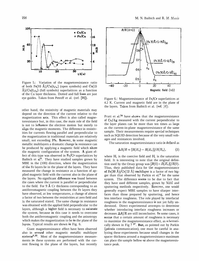
Tlie period, phase, and amplitude of the oscillations depend on the multilayer constitueiit materials and also on the crystal direction of growthl"lg. Phase and pe- riod changes occur between the (111) and (100) direc- tions in Co/Cu, and (100) Fe/Cu s ~ ~ e r l a t t i c e s ~ ~ , as shown in Fig. 5.
IV. Electronic Transport Proper t ies
Measurements of electronic transport properties in mètallic multilayers often require the same precautions as in metallic thin films. The electrical currents must be small to avoid layer damages and the experimental geometries used must take into account the fact that total thickness of these multilayer samples are usually small.
A classical theory for the conduction in thin filrns and wires in the absence of a ma,gnetic field was devel- oped by Fuchs and SondheimerZ1, and later adapted to superlattices by Carcia and SunaZ2. The presence of an applied magnetic field alter the electron motion caus- ing the conventional magnetoresistance effect. On the
M. N. Baibich and R. M . Muniz
Figure 5.: Variation of the magnetoresistance ratio of both Fe(15 A)/cu(tc,) (open symbols) and Co(15 K ) / ~ u ( t ~ , ) (full symbols) superlattices as a function of the Cu layer thickness. Dotted and full lines are just eye guides. Taken from Petroff et al. (ref. [20]).
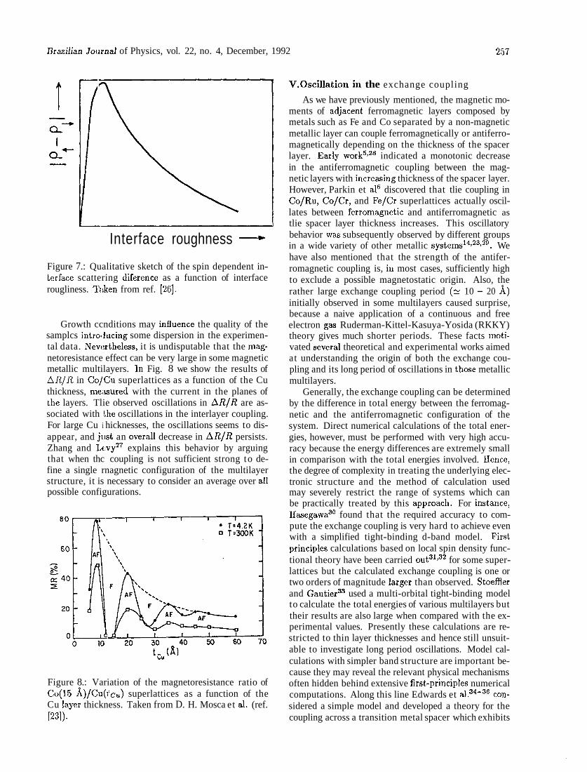
otlier hand, the resistivity of magnetic materials may depend on the direction of the current relative to the magnetization axis. This effect is also called magne- toresistance but, in this case, the main role of tlie field is not to influence the electron motion but merely to align the magnetic moments. The difference in resistiv- ities for currents flowing parallel and perpendicular to the magnetization in traditional rnaterials are relatively small, not exceeding 3%. Ilowever, in some magnetic metallic multilayers a dramatic change iii resistance can be produced by applying a magnetic field which alters tlie magnetic configuration of the system. A giant ef- fect of this type was observed in Fe/Cr superlattices by Baibich et a14. They have studied samples grown by MBE in the (100) direction, where the magnetization of the Fe layers lie in the plane of the layers. They have measured the change in resistance as a function of ap- plied magnetic field with the current also in the plane of the layers. No significant diflerence was found between tlie cases where the current is parallel or perpendicular to the field. For 9 A Cr thickness corresponding to an antiferromagnetic coupling between the Fe layers they have observed, at low temperatures, a change of almost a factor of two between the resistivities a t zero field and in the saturated stated. The same change in resistance was obtained with the applied field perpendicular to the layers, although a higher field is necessary to saturate the system, because in this case it needs to overcome both the antiferromagnetic coupling and the anisotropy which makes the magnetization to be in the plane of the layers. Typical results are shown in Fig. 6.
Giant magnetoresistance effect have been observed also in severa1 other magnetic metallic multilayer ~ ~ s t e r n s ~ ~ ~ ~ . Most of the magnetoresistance measure- ments in these systems are performed with the cur- rent flowing in the plane of the layers, but recently
-40 -20 O 20 40 Magnetic field (kG)
Figure 6.: Magnetoresistance of Fe/Cr superlattices at 4.2 K. Current and magnetic field are in the plane of the layers. Taken from Baibicli et al. (ref. [4]).
Pratt et a1.24 have shown that the magnetoresistance of Co/Ag measured with the current perpendicular to the layer planes can be more than ten times as large as the current-in-plane magnetoresistance of the same sample. Their measurements require special techniques such as SQUID detection because of tlie very small volt- ages and resistances involved.
The saturation magnetoresistance ratio is defined as
where H, is the coercive field and H, is the saturation field. It is interesting to note tliat the original defini- tion used by the Orsay group was [R(O) - R(H,)]/R(O). Tlius, their published data for the magnetoresistance of Fe(20 A ) / ~ r ( 1 2 A) multilayer is a factor of two big- ger than tliat observed by Parkin et a1.6 for the same system. The difference seems to be due to fact that they have used different samples, grown by hfBE and sputtering metliods respectively. IIowever, one would generally expect MBE samples to have sliarper inter- faces than tliose prepared by sputtering, and hence less interface roughness. The role played by interfacial roughness in the magnetoresistance is not yet fully un- derstood. Direct experimental attempts to determine whether introducing interface roughness increases or decreases ARIR are still inconclusive. In some cases, it seenls that a certain amount of roughness is necessary to maximize the magnetoresistance effect, as scliemati- cally shown in Fig 7 '?. But, as pointed out by Parkin (private communication), one must be careful in ana- lyzing these experiments because small changes in the spacer thickness around a magnetoresistance maximum can place tlie sample bellow or above the magnetoresis- tance peak.
Brazilian Journal of Physics, vol. 22, no. 4, December, 1992
J
Interface roughness -+
Figure 7.: Qualitative sketch of the spin dependent in- terface scattering diference as a function of interface rougliness. Tr~ken from ref. [26].
Growth ccnditions may influente the quality of the samplcs introducing some dispersion in the experimen- tal data. Nevmtheless, it is undisputable that the mag- netoresistance effect can be very large in some magnetic metallic multilayers. In Fig. 8 we show the results of AR/R in Co/Cu superlattices as a function of the Cu thickness, meaured with the current in the planes of the layers. Tlie observed oscillations in AR/R are as- sociated with Lhe oscillations in the interlayer coupling. For large Cu i hicknesses, the oscillations seems to dis- appear, and jiist an overall decrease in ARIR persists. Zhang and ~ c v y ' ~ explains this behavior by arguing that when thc coupling is not sufficient strong to de- fine a single rnagnetic configuration of the multilayer structure, it is necessary to consider an average over a11 possible configurations.
LU
Figure 8.: Variation of the magnetoresistance ratio of Co(15 A) /CU(I~~, ) superlattices as a function of the Cu lrtyer thickness. Taken from D. H. Mosca et al. (ref. i231
V.Oscillation in the exchange coupling
As we have previously mentioned, the magnetic mo- ments of adjacent ferromagnetic layers composed by metals such as Fe and Co separated by a non-magnetic metallic layer can couple ferromagnetically or antiferro- magnetically depending on the thickness of the spacer layer. Early work5p2" indicated a monotonic decrease in the antiferromagnetic coupling between the mag- netic layers with increasing thickness of the spacer layer. However, Parkin et a16 discovered that tlie coupling in Co/Ru, Co/Cr, and Fe/Cr superlattices actually oscil- lates between ferromagnetic and antiferromagnetic as tlie spacer layer thickness increases. This oscillatory behavior was subsequently observed by different groups in a wide variety of other metallic s y ~ t e m s ~ ~ 1 ' ~ ) ~ ~ . We have also mentioned that the strength of the antifer- romagnetic coupling is, i11 most cases, sufficiently high to exclude a possible magnetostatic origin. Also, the rather large exchange coupling period (z 10 - 20 A) initially observed in some multilayers caused surprise, because a naive application of a continuous and free electron gas Ruderman-Kittel-Kasuya-Yosida (RKKY) theory gives much shorter periods. These facts moti- vated severa1 theoretical and experimental works aimed at understanding the origin of both the exchange cou- pling and its long period of oscillations in those metallic multilayers.
Generally, the exchange coupling can be determined by the difference in total energy between the ferromag- netic and the antiferromagnetic configuration of the system. Direct numerical calculations of the total ener- gies, however, must be performed with very high accu- racy because the energy differences are extremely small in comparison with the total energies involved. IIence, the degree of complexity in treating the underlying elec- tronic structure and the method of calculation used may severely restrict the range of systems which can be practically treated by this approacli. For instance, l1asegawa3' found that the required accuracy to com- pute the exchange coupling is very hard to achieve even with a simplified tight-binding d-band model. First principles calculations based on local spin density func- tional theory have been carried out3lJ2 for some super- lattices but the calculated exchange coupling is one or two orders of magnitude larger than observed. StoefHer and G a ~ t i e r ~ ~ used a multi-orbital tight-binding model to calculate the total energies of various multilayers but their results are also large when compared with the ex- perimental values. Presently these calculations are re- stricted to thin layer thicknesses and hence still unsuit- able to investigate long period oscillations. Model cal- culations with simpler band structure are important be- cause they may reveal the relevant physical mechanisms often hidden behind extensive first-principies numerical computations. Along this line Edwards et a1.34-36 con- sidered a simple model and developed a theory for the coupling across a transition metal spacer which exhibits
258 AI. Ar. 13aibicli and R. AI. Muniz
many of the observed features of tlie oscillatory intcr- laycr coupling.
IIere, for preseiitation purposes, we distinguish be- tween noble aiid transitioii metal spacers and divide esistiiig tlieoretical works into two different (but in our vicw complemeiitary ratlicr tlian competing) types of approach. Tlieories of tlie excliange coupliiig bascd on total energy calculations like tlie ones we liave briefly nientioiied, aiid RKKY-type of theories in wliicli the escliange iiiteraction between localized momeiits medi- ated by coiiduction electrons are calculated by pertur- bation theory37-42.
For noble metal spacers, with tlie d bands well bcl- low tlie h r m i leve1 aiid a broad nearly-free-electron sp conduction band, it is diflicult to conceive any- tliiiig niuch different froin a RKKY-like coupliiig. As a sccond order perturbation tlieory, RKKY is not ex- pected to provide a good dcscription of tlie coupling for tliin spacer layer tliicknesses. IIowever, in tliis case, first-priiiciples total energy calculations lias a cliaiice of yielding accurate rcsults for the coupling. Ori tlie other haiid, in tlie opposite limit (i.e. for very large spacer layer tliickiiesses) total energy calculations are very Iiard to deal witli inmcrically, but RKKY may provide a inucli siinpler approacli. Nevertheless, it is difIicult to calculate tlie strengtli of the coupling wit,liin RKKY, wliere usually tlie value of tlie coupling ulti- mately dcpeiids on a ratlier arbitrary choice of values for tlie parameters involved.
Asymptotic beliavior conceriiing tlie period of oscil- lation, rate of decay and tcmperature dependente ob- tained from RKKY~' agree with tlie niodel calculatioiis of Edwards et a134135. 111 botli tlieories tlie occurrence of long pcriod oscillations in tlie cxchange coupliiig is iii- tiinately associated to thc discrete nature of tlie spaccr Iaycr. For a ooe-band tiglit-binding rnodel witli nearcst plane liopping, and layer orientation correspondiiig to a plane of reflectioii syinmetry iii tlie spacer, Edwards et a135 slioived tliat tlie period of oscillation is deter- mined by caliper nieasuremci~ts of tlie spacer Fcriiii sur- face normal to tlie layer planes, and long-periods arise wlieii tlie Fermi surface is dose to tlie zone boundary. C o e l i o o r ~ i ~ ~ (see also Cliappert arid R e ~ i a r d ~ ~ ) drew similar conclusions by analyzing in real space tlie ra- tio between tlie period of the spin density oscillatioiis induced in the conduction clectroiis and tlie discrete spacer layer thickness.
Tlie RKKY range function iii a planar geometry may be ~ a l c u l a t e d ~ ~ by taking the one dimeiisional Fourier transform of the wavevector-dependeiit suscep- tibility ~ ( q = O, qt ), wliere q and q, are tlie components of tlie wave vector parallel and perpendicular to tlie lay- ers respectively. Asymptotically, significant coiitribu- tions to the range function mainly comes frorn wave vec- tors which maximize x, lierice long period oscillations iii tlie interlayer coupliiig are associated with singularities in ~ ( q ~ ) . Bruno and ChapPert4' have analyzed buIk
Fermi surfaces of Cu, Ag and Au in ali extended zoiie sclieine to identify tlie extrema in x aiid determiiied tlie relevant wave vectors for the iiiterlayer coupling peri- ods of oscillations in different crystalline orientations. For (111) Cu spacer layer they predictcd a uiiique pe- riod of r 9.4 A in very good agreemciit witli tlie value observed iii Co/Cu sainples predoniiiiantly tcstured in the (1 11) directionZ3.
For traiisition iiietal spacers witli partially filled (1- barids tliere is no rcason to expect a simple nearly-frec- electron like polarization of tlie type usually considcred by RKKY. A complcte treatinent of tlie polarization involving tlie d-bands would be mucli more iiivolved. \lTang et a139 used a tlieory4' originally developed for rare earth cornpouiids to study the interlayer coupling in I+/&. In tlieir calculations tliey liave used full band structiire of bulk paramagnetic Cr but tlie f and 1 spins k d-bands were substituted by atomic levels locatcd below aiid well above tlie Fermi encrgy rcspectivcly. Tlic magnitude of the coupliiig was fouiid to be strongly dependent on tlie estiinated values of Lhe position o[ tlie f spin Fe d-leve1 relative to the Fermi cnergy, and a second paraincter was used to set tlie final coupliiig en- ergy scale. Ferromagnetic transition mctals separatcd by transitioii metal spacers should liave tlieir d-bands treatcd on eqiial footing, aiicl preferahly witliin an itin- erant picture because tliey are not localized. Conse- qiiently, i11 tliis case, a more careful treatinciit of tlie elec tron spin iii teractions is required.
We now briefly describe tlie tlieory of Edwards et ai3' for tlie iiiterlayer coupling across a transition metal spaccr. For tliis purpose, it is suficiciit to consider two semi-iiifinite traiisition nletal fcrromagnets sepa- rated by a traiisition mctal spacer contaiiiing N atomic planes. The exchaiige coupling J (AT) is givcn by tlie diffcrence in energy, per unit area of tlie layers, be- tweeii tlie fcrromagnetic and antifcrroinagnetic config- uratioiis of tlie saiidwich. For simplicity it is assuiiied tliat d-bands contributioiis to tlie energies are doininaiit aiid hence tlie s p conduction band is omitted; total cn- ergics of tlie two coiifigurations are approxiinated by one-electroii energy sums. Tlie Fermi levcl is fised by tlie bulk fcrromagnets aiid tlie spaccr aligned accord- ingly. Cliangcs in tlie d-levcls in eacli atomic plane witli rcspcct to tlieir appropriate bulk values are ncglectcd, tliereby avoiding a self-consistency wliich would sliglitly cliangc tliese lcvcls near tlie interfaccs. To make tlie calculations evcn simpler we furtlier assume tlie same d-band widtli for botli inagiietic and noii-niagnetic niet- als, and tliat tlie iiuniber of 1 spins electrons per atom in tlie magnctic inctal is cqual to tlie nuinber of electrons pcr atom of cither spins i11 tlie non-magnetic mctal. To einpliasizc tlie basic physical mcchanism we initially consider tlie case in wliich tlie f spin electron d band of tlie ferroinagiict is full. In sucli a case, when tlie sandwicli is in tlie fcrroinagiietic configuration, thc f spin Iioles experiente a constant potential tlirougIiout
tlie structurr, whereas 1 spin holes feel a potential well in tlie spacer layer. The well is caused by the excliange field wliicli increases Lhe nuniber of f spin electrons in tlie ferroina,;nets in both sides of tlie sandwich in tlie parallel con'iguration, lience reducing the 1 spin lioles occupation n these regions. Tlie presence of the well confine the , spin lioles essentially in the non-magnetic spaccr metal, and introduces size quantization effects wliicli clear!y depend on tlie spacer layer thickness. \\:licn tlie s: ndwich is in the antiparallel configuration, f spin lioles expericnce a potential step when crossiiig tlie second nterface, and 1 spin lioles feels a similar stcp when crossing the first interface. It follows tliat, in tliis configuration, 1 spins holes are confined in tlie lialf space tc tlie left of tlie second interface, and 1 spin liolcs iii tlie half to tlie riglit of the first interface. The situation is 5 chematically shown in Fig. 9 for botli con- figurations and spin directions. The well depth, and liciglits of the two steps, depend on the excliange split- tiiig of tlie fc rromagnets and control the effectiveiiess of tlie coiifinenicnts. A very simple model is to consider tlie 011-site interaction U = oo in tlie magnetic layers aiid U = O in tlie spacer layer. In tliis case, 1 spins d lioles are r:ompletely confined in the spacer layer in tlie fcrromag;netic configuration, and tlie cost in energy to produce :ucli a confinement clcarly depends on tlie spacer tliick iess. On tlie other liand, in tlie antiferro- magnetic co lfiguration, tlie lialf space confinement of eacli spin d holes is caused by a single surface t e m , and lience tlie associated cost in energy is independent of tlie spacer tliickness. Therefore, qualitatively, it is tlicn conceivable that the energy cost to obtain a ferro- magnetic coiifiguration may be sometimcs higher some- tiines lower ,han tlie antiferromagnetic one, depending on tlie spacer layer thickness.
Tlie interlayer coupling is proportional to tlie encrgy diflcrence between the parallell and antiparallel config- urations of tlie sandwich, witli constant liole number, aiid is given by
wliere R(N) is the free energy which at zero tempera- ture reduces to
IIere, E(N) s the total energy of the 1 spins holes con- fincd in a s p x e r with N atomic planes, measured rcla- tive to a refei-ence state with N bulk planes; n(N) is tlie corresponding number of lioles; EF is the Fermi energy, S2(co) is the constant ( N iiidependeiit) surface term preseiit in th r antiferromagnetic configuration, and A is tlie area of the layers. At zero temperature R(N) inay be calculatetl by
Figure 9.: Schematic representation of tlie densities of states for eacli spin N l (E ) and NI(E) in eacli region of a sandwich for (a) ferromagnetic aiid (b) antiferro- magnetic alignments of the magnetic layers; the vertical axis is drawn at the Fermi level EF. Inset: Schematic plots of tlie potentials experienced by tlie lioles of dif- ferent spins in eacli case (dashed line for 1 spin Iioles, solid line for spin liolcs).
where Ap is tlie change in tlie density of states of tlie confined holes relative to bulk referente system.
Tlie confinement quantizes tlie 1 spin hole states in tlie direction perpendicular to the layers and this shows up as steps in tlie corresponding density of states. The number, heiglits and position of tliese steps de- pend on the widtli of tlie well, as in the case of a film where the'y depend on the film thickness. As the spacer layer thickness changes, these steps move and may cross tlie Ferrni level, leading to oscillations in the exchange coupling. The situation is similar to the de IIaas-van Alplien (dHvA) effect in which oscillations are asso- ciated with the quantization produced by an applied magnetic field. IIere, ihe quantization is imposed by the excliange field and tlie variation of the spacer thick- ness causes tlie quantized states to pass tlirough EF. Exploiting this analogy witli the dIIvA, and consider- ing a simple one-band tight-binding model with nearest plane hopping, and layer orientation corresponding to a plane of reflection symmetry in the spacer, Edwards et al. derived tlie following asymptotic formula for the interlayer coupling
M. N. Baibich and R. M. Muniz
exp[2is Nak," (p)]
T-l sinh [ 2 n s N a ~ % ]
both 2nd derivatives > O a = [ i , both derivatives < O
( 1, one derivative > 0, the otlier < 0. (7)
The formula is valid for finite temperature T as well a s T = 0, and it is exact for this particular rnodel, where U = oo in tlie magnetic metals and equal to zero in the spacer layer. IIere, kt(p) is an extremal radius of the Fermi surface in the direction perpendicular to the layers (half the caliper measurement) and a11 the derivatives in Eq. 7 are taken at the stationary point k," r k:(p, kg(p), k:@)); a is the lattice parameter and p the chernical potential fixed by the ferromagnets (at T = O p = EF). The consequences of this asymptotic formula for J ( N ) are:
(i) The period of oscillations in the exchange cou- pling is determined by the factor exp[2iNab,"(p)]. Clearly, owing to the discrete thickness Na of tlie spacer layer, k,"(p) may be replaced by k ; ( p ) - n/a. Therefore, long periods are obtained either when the radius k,0(j~) is small or when the Fermi surface approaches the zone boundary a t ?r/a so that k;(p) - ?r/a is small.
(ii) The amplitude contains a factor of the Ferrni surface a t its extrema1 points.
(iii) The temperature dependente of the oscillations is governed by the velocity of carriers a t the extremal points.
(iv) The asymptotic decay a t T = O is proportional to 1/N2 but becomes exponential a t finite T.
Numerical calculations for specific cases of a one- band model and simple cubic (100) orientation of the layers at T = O show that the asymptotic formula given by Eq. 7 is rather accurate for N > 5. In this case, long period oscillations are obtained for EF 2 -1, which corresponds to a situation where the Fèrrni surface is close to the zone boundary. For EF = -1.05 the sign of J for N r= 5 is antiferromagnetic, and the period is E 10 interatomic distances, which is close to what was observed in structures like Co/Ru3. Also, the mag- nitude of J, calculated with this value of EF and for a spacer thickness of a few atomic planes, is S 1 erg ~ m - ~ , which is of the order of magnitude of the Co/Ru measured value.
For EF = -0.95 the period is again long, but there is a phase shift in the oscillations compared with EF = -1.05. For EF > -1, the Fermi surface develops four necks in the plane parallel to the layers (equivalent to two saddle points) and the diameter of the necks is small for EF = -0.95. These necks are the extrema that determine the oscillations in the exchange coupliiig for -1 < EF < 0, and the phase shift is obtained because
tlie factor a in Eq. 7 takes a value a = 1 for a saddle point.
Short period oscillations can be obtained for exam- ple with EF = -2.5. In this case the amplitude of oscillations is bigger than those with EF S -1 because of the greater curvature of the Fermi surface at tlie extremum. In practice, roughness of the surfaces may lead to a variable effective spacer thickness which would tend to suppress sliort-period oscilIations, sucli as those with EF = -2.5, due to an averaging effect.
The theory described so far was developed assuming a complete confinement of holes. Tliis is a very strin- gent assumption wliich clearly should be relaxed for a weak ferromagnet like Fe which has cl-lioles in both mi- nority and majority spin bands. In this case, lioles are not totally confined inside the spacer layer, neitlier in half spaces. To investigate the effect of partia1 hole ~ o n f i n e m e n t ~ ~ , we need to consider a finite excliange splitting V in the magnetic layers. For simplicity, we avoid a full self-consistent treatment of tlie problem and assume a simple picture in which the effective on-site energies are taken to be zero inside the spacer layer, and eitlier V or O inside tlie magnetic metals, depeiiding on the configuration and spin directions of the lioles. Thus, the steps at the interfaces have lieight V, and basically two situations may occur. The first, wliich is pictured in Fig. 9, is when EF < V as in Co. 111 this case, for finite V, J. spin holes can penetrate a few layers across the interfaces inside the magnetic met- als in the ferromagnetic configuration; the confinement will not be precisely restricted to thc spacer layer, but still will be essentially within a finite region. Similar penetrations will also happen in tlie antiferromagnetic arrangement through the corresponding finite potential step experienced by holes of either spins. The other sit- uation is when EF > V. In this case, there are hoies of both spins in tlie magnetic metals (as in Fe), and they are only partially reflected by the potential steps at the interfaces. In the ferromagnetic configuration reso- nances may occur in the 1 spin holes for a fixed value of V as the spacer thickness vary.
To calculate tlie interlayer coupiing at T = O, we can still use Eqs. 4-6, but a Green function method is required to calculate Ap 36, which is then given by
where AGnn(E, k) is tlie difference between the diag- onal element of the Green function in atomic plane n and the appropriate reference bulk Green function, and k is a two-dimensional wave vector parallel to the lay- ers. For the fcrromagnetic configuration where tlie J. spin lioles move in a potential well of depth V we may rewrite
262 M . N. Baibich and R. 111. Muniz
local mean free paths) are different for electrons with for f spins, and dillèrent spins and depend on wliether the multilayer is on a ferromagnetic or antiferromagnetic configura- ( ~ t i t ~ + N~J')/(A.I + N), (12) tion. In Fig. 11 the distribution of local re~ist~ivities in tlie magnetic superlattice ceIl is sllown schematica]ly for 1 spins, u.here A l and N are tlie tl~icknesses of tlie for each spin channel and for the ferromagnetic and an- nlagnetic and non-magiietic layers respectively. 1t is
tiferromagnetic configurations of tlie multilayer. clear from tliese equations (or Fig. 11) that tlie lowest average resistivity occur for the f spin electrons in tlie
FERROMAGNETK: C ~ F ~ R , Q - I O N A N T I F E ~ ~ N U C C C I ( F ~ R A T ~ ferromagnetic configuration. Ttiis channel then acts as
M N M N M N M N a sliunt, making RTt smaller than Rtl . Also, froni tliese straightforward averages, it follows tliat AR/R is given
1 i!, 1 m'in
q h by
AR/R = ( a - PI2 I 4(ru + N/M)(B + N/M) ' (13)
where cw = t,/Cmin and /3 = CS/Cmaj. Tliis very sim- ple analytic formula, althougli valid only in tlie litnit of very long mean free paths, helps to understand severa1
Figure 11.: Schematic representation of tlie distribution of local mean free paths P1 in tlie magnetic unit cell for tlie ferrornagnetic and antiferromagnetic configurations of the magnetic layers. Both the resistivities in the spin r and spin 1 cliannels are sliown. h l and N denote, respectively, the magnetic and nonmagnetic layers.
When the current flows parallel to the layers it is instructive to consider two extreme limits: First, when tlie longest mean free path is mudi sliorter than any of tlie layer thicknesses. In this case, electrons of a given spin will liardly sample different layers, which means tliat the layers will behave essentially as resistors in parallel. It is then clear that, in this case, there will be no magnetoresistance effect, i.e. AR/R = O, be- cause the amount of high and low resistivities cliannels to be added in parallel wilI be exactly the same for both configurations of the multilayer. The second, and opposite limit, is when the mean free paths are mucli longer than tlie layer thicknesses. In this case, elec- trons of a given spin will sample many layers and will experience an average resistivity. One way of generally working out this average for superlattices is by numer- ically solving the Boltzmann equation with continuity and periodic boundary conditions imposed on tlie dis- tribution f ~ n c t i o n ~ ~ ~ ~ ~ . However, in tlie very Iong mean free path limit, a conduction electron with spin u shall equally sample a11 the layers and will experience a very simple average resistivity. More specifically, in such an extreme limit, the average resistivity for each spin in tlie antiferromagnetic configuration will be proportional to
whereas in the ferromagnetic configuration the corre- sponding average resistivities will be proportional to
of the magnetoresistance features observed in metallic multilayers. It is clear tliat for fixed a , P and MARlR decreases as a function of N. Actually, we can see i11 Fig. 12 tliat Eq. 13 provides a good iit to the experi- mental data for reasonable values of tlie parameters a and p.
It is also clear tliat to obtain a large AR/R we necd N/M as small as possible, C, as large as possible, and principally either a/P or @/a as large as possible. Tliis explains wliy CoCu with both large ratio cr/P and e, is sucli good a combination to produce large niagne- toresistance effect. If Co is substituted by Fe, i.e. if a FeCu superlattice is considered, tlie situation is sliglitly different. The Fermi level in Fe lies in a dip of the minority spin density of states and tEaj < E%,, lience ( , f3 /c~)~~ > 1. I-Iowcvcr, the important thing is tliat tlie ratio (P/(Y)~, (roughly estimated from bulk density of states calculations5" is srnaller than the corresponding ratio (CY/P)~, , causing the magnetoresistance of Fe/Cu to be sinaller than tliat of Co/Cu as observed".
When irnpurities are added to the spacer metal turiiing it into an alloy, for a fixed A l and N tlie ra- tio (cw/P) associated to the bulk ferromagnetic metal is kept essentially constant but t, clianges. In tlie low impurity concentration limit tlie decrease i11 e, is proportional both to tlie impurity concentration x and to the strength of the impurity scattering po- tential. Therefore, AR/R decreases with increasing x, and the decrease is more pronounced for impuri- ties with larger ~ A z J , where IA21 is tlie difference be- tween the atornic numbers of tlie two alloy components. Tliis was observed5' in Fe/(XxCrl-,) superlattices for X = Ti, V, Mn (among others elements), and analyzed along these lines by Edwards et aI6'. The situation when impurities are added to the ferromagnetic metal is more subtle. It is well known that impurities in ferromagnetic transition metals can produce significant clianges to their electronic structure and these changes may be very different for the two spins directions. Vir- tual bound states may pass tlirough the Ferrni level,
split ofl froin the bands; screening effectiveness is usu- ally spin de ~endent and may vary, among other tliings according to the impirrity type, and as to wliether tlie rnatrix is a strong or a weak f e r r o n ~ a ~ n e t ~ ~ > ~ ' - ~ ~ . As conscquencc, alloying tlie ferromagnet generally affect diflcrently t'ie density of states for electrons with differ- ent spins, a l d in many cases drastically changes both tlie inagnetic and the transport properties of the ferro- magnct. Fel t and Campbel164 liave made an exteiisive and detailed investigation of tlie effect of diluted impu- ritics in the transport properties of bulk ferromagnetic transition metals. Tliey have sliown that emaj and emin (hcnce tlie r stio a/P) may vary considerably according to Lhe combination of tlie alloy components. The extent to wliich tlie clianges in tlie magnetoresistance correlate to tlie chaiil:es in the alloy density of states as differ- ent alloy coiistituents are cliosen for tlie ferromagnetic layers would be a good test to verify the importance of tlie present nechanism.
The simple formula on whicli we are basing our dis- cussion obviwsly lias limitations. It is valid when a11 tlie mean frre paths are longer than the superlattice cell but this is not true in many cases. For example, Eq. 13 indicates that ARlR increases with increasing h1 (saturatiiig at a value ( a - P)2/4aP when A4 -+ oo), but it clearl'l stops being valid wlien h4 is longer than tlie shortest mean free path. In this case, as previously mentioned, we have to solve the Boltzmann equation to work out properly the average resistivities sampled by tlie cond lction electrons with different spins. The sliorter tlie nean free paths, relative to the layer tliick- nesses, the narrower will be tlie region effectively sam- pled, which rauses the magnetoresistance to decrease. Tlierefore, t i e magnetoresistance may initially increase with increasing M but it should reach a maximum and tlicn dccreases as M gets longer and we deviate further from tlie uniform sampling and approach its opposite limit where the magnetoresistance is zero. A simple calculation shows that large deviations from tlie uni- form samplirig limit occur for mean free paths shorter than approximately 1 1 4 ~ ~ of the superlattice ~ e l l ~ ~ . In a Co/Cu su~erlattice for example, a more refined tlie- oretical a n a l y ~ i s ~ ~ of the data based on the solution of the Boltzmarin equation gives tmin 12 A, emaj E 130 A and e, E 260 A. The full solution shows that in Co(M)Cu(9 L) superlattices ARIR passes through a maximum at M E emin, whereas the forrn of A R l R as a function of N does not depend much on &,in for M < &,. 'l'he maximum at h4 E 12 A in C o ~ C u g superlattices indicates that for M > 12 A significant deviations from the uniform sampling becomes impor- tant, which ic. consistent witli !,i, being less than 1 /4th of the magnc tic superlattice cell. It is therefore clear that for a larger Cu spacer as in CoMCuzo superlat- tices the maximum, if it occurs, would certainly be at a vaiue of M. < 12 A (possibly at M < 4A) as the experimental data of ~ o s c a ~ ~ suggests.
O 10 20 30 40 50
Cr thickness (A)
Cu thickness (A)
Figure 12.: (a) Dependence of ARIR on Cr tliickness for Fe(20 A)/cr(tc,) superlattices. The full line is cal- culated by Eq. 13 with a = .4 and /3 = 2, and the experimental data is taken from ref. [G]. (b) Depen- dente of ARIR on Cu thickness for Co(l0 A) /~u ( t c , ) superlattices. The full line is calculated by Eq. 13 with a = 10 and p = 1.3, and the experimental data is taken from from Parkin et alZ3.
Let us now briefly discuss the role played by inter- facial scattering in the magnetoresistance effect. Gen- erally there will be a mismatch on tlie bottoms of the conduction bands of the two metals separated by an interface. In this situation, the conduction electrons would experience a potential step when crossing the in- terfaces. However, for interfaces between two transition mctals or between transition and a noble metals these steps are small compared to the Ferrni energy hence, as a reasonable approximation, they may be neglected. Nevertheless, wlien the interface is not sharp the two metals mix and in thc most simple picture will form an alloy. As we previously mentioned, alloying a fer- romagnet may significantly alter tmin and lmaj hence the asyrnrnetry ratio a//3. Other effects due to lattice spacing mismatcli between the two metals, existente of terraces, structural defects etc ... may also contribute
A r . N. Baibich and R. 31. Muniz
to make the asymmetry in scattering at the interfaces be very different from its corresponding bulk value. A transport theory including a detailed description of tlie possible inliomogeneities at tlie interfaces would ccr- tainly be too laborious. A very simple approacli is to treat the interface as a third material in whicli the as- sociated mean free paths tmin and tmaj are considered as arbitrary parameters. Sucli treatinent ignores vari- ations in tlie composition witliin tlie interface widtli, wliich is reasonable when both mcan free paths are long on the scale whcre sucli variations occur. In tliis case, tlie Boltzmann equation nceds to be solved for a eight- componcnt system instead of four when interface scat- tering is neglected. \Vitliin tliis straightforward gencr- alization, tlie two additional parameters ti,, aiid tiaj associated witli tlie interfaces may also be determiricd so as to fit experimental data, and, in this way, tlie rel- ative iinportance betwcen bulk and interface scattering could be estimated for a particular systern. 1% should bear in mind tliat tlie magnctoresistance effect depends on tlie widtli of tlie region effectively sanipled by tlie conduction electrons. To obtain tlie effcct it is esseii- tia1 tliat at least two magnctic layers are samplcd (from rig. 11 we can clearly see tliat if pairs of inagnetic/non- inagnetic layers are trcated as resistors in parallcl tlicre will be no magnctorcsistance effcct). Tlierefore, thc rcl- ative importance between bulk and interfacial scattcr- i i ~ g iii AR/R may also depend or, tlie rclation bctwccn tlie mean free patlis and the layer tliicknesses, because in some cases it may Iiappen that only a fraction of tlie inagnetic layers are effectivcly sampled. Clearly, bettcr experimental charac terizatioii and control of i11 ter face quality will be decisive on establisliing wlietlicr bulk or iritcrface scattcriiig dominates in eacli case. Rcliable tlieoretical calculations of tlie clectroriic structures are also very important to understaiid tlie clianges wliicli occur at tlie interfaces and liow tliey correlate to tlie assymmetry i11 tlie scattering of clectrons witli diffcrcnt spiiis.
Most of tlie theoretical ideas and calculations pre- sented here by one of us (RBM) are the product of an eiijoyable collaboration with D. M. Edwards and J . Mathon. IIe would like to thank tliem for their con- staiit teachings and for making his learning of tliis sub- ject so pleasurable. Very useful discussions witli Dr. J . d'Albuquerque e Castro, Dr. AIurielle Villaret Prof. A. A. Gomes and Prof. A. Fert are also greatfully acknod- edged by the authors. We acknowledge partia1 financia1 support provided by CNPq and FINEP.
1. P. J. Flanders, J . Appl. Phys. 63, 3940 (1988).
2. L. M. Falicov, D. T . Pierce, S. D. Bader, R. Gron- sky, K. B. EIatliaway, 11. J . Hopster, D. N. Lain- beth, S. S. P. Parkin, G. Pririz, hI. Saloinon, I. I(. Schuller, aiid R. H. Victora, J . RIatcr. Rcs. 5 , 1299 (1990).
3. R. Kr ishan , H. Lassri, RI. Porte, RI. Tessier, aiid P. Rcnaudin, Appl. Pliys. Lett. 59, 3649 (1901); R. Krislinan, M. Porte, and RI. Tessier, IEEE Traiis. Rlagn. 26, 2727 (1989).
4. M. N. Baibich, J . RI. Broto, A. Fcrt, F. Ngnycn Van Dau, F. Petroff, P. Etieiinc, G. Creuzet, A. Friedericli and J. Chazelas, Pliys. Rev. Lett G1, 2472 (1988).
5. P. Gruiibcrg, R. Sclireiber, Y. Paiig, RI. N. Brod- sky and 11. Sowers, Phys. Rev. Lctt. 571, 2412 (1086).
6. S. S. P. Parkin, N. Rfore and I<. P. Roclie, Pliys. %v. Lett. 641, 2304 (1990).
7. J. F. RI. Borgcs, G. Tosin, L. F. Sclielp, N. hIatoso, S. R. Teixeira, D. 11. RIosca, \IT. 11. Sclirciner (to be publislicd).
9. F. J . A. dcn Brocder, 11. J . G. Draaisina, 11. C. Doiikcrsloot, and \IT. J . RI. de Jonge, J . App1. Pliys. 61, 4317 (1987).
10. U. Cradnmn and S. F. Alvarado, SiirJuce C r y ~ t d - lography, (Springcr Verlag, Berlirn, 1079).
11. A. Bartliélcnly, A. Fert, RI. N. Baibicli, S. IIad- joudj, F. Pctroff, P. Etienne, R. Cabaiicl, S. Lcquicn, F. Nguyen Van Dau, and G. Creuzet, J. Appl. Phys. 67, 5908 (1990).
12. C. Liu, E. R. Rloog, and S. R. Bacler, Pliys. Rcv. Lctt. 60, 2422 (1988); T . Katayama, Y. Suzul<i, 11. Awand, Y. Nishirara, and N. Kosliizuka, Pliys. Rev. Lett. 60, 1426 (1988).
13. F. Nguycn Vali Dau, A. Fert, P. Etienne, RI. N. Baibicli, J . Af. Broto, G. Creuzct, A. Friedericli, S. IIadjoudj, 11. IIiirclcquint, and J. AIassics, J. P1iys. (Paris) Colloq. 40 C8, 1633 (1988).
14. P. Grünbcrg, S. Demokritov, A. Fuss, h l . \'olil, aiid J. A. \ITolf, J. Appl. Pliys. 60, 4780 (1991).
15. S. T. Purccll, \V. Folkerts, RI. S. Jolinson, N. VCT. E. RIcGec, 11;. Jager, J . aan de Steggc, \V. B. Zeper, and \.V. IIoving, Pliys. Rcv. Lctt. 67, 903 (1991).
16. S. Dcniokritov, J. A. \TTolf, and P. Grünberg, Eu- ropliys. Lctt. 15 , 881 (1991); P. Grünberg, J. AIagn. AIagn. RIatcr. 104-107, 1734 (1992).
17. J . Uilguris, R. J . Cellota, aiid D. T . Picrce, Pliys. Rev. Lett. 67, 140 (1991)
18. AI. T. Johnson, S. T . Purcell, N. TV. E. RIcGcc, R. Coehoorn, J. aan de Stegge, and W. IIoving, Phys. Rev. Lett. 68, 2688 (1902); and rcferenccs Ilierein.
19. 1'1'. E'. Egelhoff Jr., and AI. T . IGef, Phys. Rev. I1 45, 7795 (1992); see also ref. 56.
Drazilian Journal of Physics, vol. 22, no. 4, December, 1992
20. F. Petioff, A. Barthélemy, D. 11. hlosca, D. 'K. Lottis, A. Fert, P. A. Sclioeder, 1V. P. Pratt Jr., R. Lalcee, and S. Leqiiien, Pliys Rev. B 44, 5355 (1991).
21. I<. Fucis, Proc. Caiiib. Pliil. Soc. 34, 2000 (1938); E. 11. Sondlieinier, Adv. Pliys. 1, 1 (1952).
22. P. F. C'arcia and A. Suna, J . Appl. Phys. 54, 2000 (1183).
23. D. 11. hcosca, F. Petroff, A. Fert, P. A. Schroeder, \V. P. I'ratt Jr. and R. Laloee, J . RIagn. Rlagn. Ríat. 94, L1 (1991); S. S. P. Parkin, R. Bhadra aiid I<. P. Roclie, Pliys. Rev. Lett. 66, 2152 (1991); A. Fert, A. Bartlieléniy, P. Etienne, S. Lequicn, R. Laloee, D. I<. Lottis, D. 11. hIosca, I?. Petroff, W. P. Pratt, and P. A. Schroeder, J . Aíagn. Irfagn. Mater. 104-107, 1712 (1992).
24. 11'. P. I'ratt Jr., S. F. Lee, J. RI. Slaughter, R. Loloee, P. A. Schroeder, and J . Bass, Pliys. Rev. Lett. 66, 3060 (1991).
25. P. RI. Levy, S. Zhang, and A. Fert, Phys. Rev. Lett. 65, 1643 (1990).
2G. TV. Folkerts, JY. Hoving, and W. Coene, J . Appl. Pliys. 7 L , 362 (1991).
27. S. Zliani;, and P. hl. Levy (preprint). 25. C. Carbone and S. F. Alvarado, Phys. Rev. B 36,
2433 (1987). 29. B. IIeiniich, Z. Celinski, J . F. Cochran, W. B.
Aluir, J . Rudd, Q. hI. Zhong, A. S. Arrot, K. Myr- tle and 7. Kisliner, Phys. Rev. Lett. 64, 673 (1990); 'V. R. Bennet, \V. Schwarzacher and W. F. EgellidT Jr., Phys. Rev. Lett. 65, 3169 (1990).
31. P. RI. L e ~ y , K. Ounadjela, S. Zliang, Y. Wang, C. 13. Somrrers and A. Fert, J . Appl. Pliys. 67, 5914 (1990).
32. F , IIerman, J . Sticlit and AI. Van Schilfgaarde, J . Appl. Pliys. 60, 4783 (1991). Magnelic Thin Fzlms Multilayers and Surfaces, ed by S. S. P. Parkin et al, AIRS Symposium Proceedings 1992, Vol. 231 (to be published).
33. D. StoefRer and F. Gautier, Progr. Theor. Phys. Suppl. 1131, 139 (1990); J . of Magn. and Magn. hlater. 104-107, 1819 (1992).
34. D. M, EdT~ards, J . Mathon, R. B. Muniz and M. S. Phan, J. Phys.: Condens. Matter 3, 3941 (1991).
35. D. M. Edwards, J . Mathon, R. B. Muniz and M. S. Phan, Phys. Rev. Lett. 67, 493 (1991); 67, 1476(E) (1991).
36. D. M. Edwards, J . Mathon and R. B. Mu- nia, Physica Scripta 1992 (to be published); J. hlathon, Murielle Villeret, D. M. Edwards, and R. B. Muliz, J . of Magn. and Magn. hlater. (to Ee publislied); J. Mathon, Alurielle Villeret, and D. M. Edwards, J. Phys.: Condens. Matter (to be published 1.
37. S. J . Frisl.en and D. J . hililler, Phys. Rev. Lett.
57, 2971 (1986). 38. W. Baltensberger and J . S. Helman, Appl. Pllys.
Lett. 57, 2954 (1990). 39. Y. Wang, P. M. Levy and J. L. Fry, Phys. Rev.
Lett. 65, 2732 (1990). 40. P. Bruno and C. Cliappert, Phys. Rev. Lett. G7,
1602 (1991). 41. C. Lacroix and J. P. Gavigan, J . Rlagn. Magn.
IiIater. 93, 413 (1991). 42. L. hl. Roth, 11. J . Zeiger and S. A. Kaplan, Phys.
Rev. 149, 519 (1966); F. IIerman aiid R. Sclirief- fer (preprint).
43. R. Coehoorn, Phys. Rev. B 44, 9331 (1991). 44. C. Chappert and J . P. Renard, Europhys. Lett.
15, 553 (1991). 45. Y. Yafet, J . Appl. Phys. 61, 4058 (1987). 46. C. E. T. Gonçalves da Silva and L. hf . Falicov, J .
Phys. C: Sol. Stat. Phys. 5, 63 (1972). 47. P. Bruno (preprint). 48. N. F. Mott, Adv. Pliys. 13, 325 (1964). 49. J . RI. Ziman, Electrons and Phonons - The Inter-
national Series of Rlonographs on Pliysics, ed. by N. F. Mott, E. C. Bullard and D. TVilkinson (Ox- ford University Press, Oxford, 1960).
50. R. E. Camley and J . Barnás, Phys. Rev. Lett. 63, 664 (1989).
51. J. Barnás, A. Fuss, R. E. Camley, P. Grunberg and W. Zinn, Phys. Rev. B 42, 8110 (1990).
52. D. M. Edwards, R. B. Muniz and J . Mathon, IEEE Transactions on hlagnetics 27, 3548 (1991).
53. D. hf. Edwards, J . Mathon, R. B. RIuniz and S. S. P. Parkin, J . Magn. Ivlagn. Mat., 1992 (to be published).
51. B. Dieny, V. S. Speriosu, S. Metin, S. S. P. Parkin, B. A. Gurney, P. Baumgart and D. R. Wilhoit, J. Appl. Phys. 69, 4774 (1991).
55. E. E. Fullerton, D. M. Kelly, J . Guimpel, I. K. Scliuller and Y. Bruynseraede, Phys. Rev. Lett. 68, 859 (1992).
56. D. Greig, M. J . IIall, C. IIammond, B. J . IIickey, H. P. 110, M. A. IIowson, M. J . \TTalker, N. Wiser and D. G. Wright, J. Magn. Magn. Mat. 1992 (to be published).
57. S. S. P. Parkin Appl. Phys. Lett. 61, 1358 (1992). 58. V. L. Moruzzi, J. F. Janak and A. R. Williams,
Calculated Electronic Properlies of Metals (Perg- amon, New York, 1978).
59. K. Takanashi, Y. Obi, N. Tsuda and H. Fujirnori (preprint).
60. D. M. Edwards, J . hlathon, and R. B. Muniz (to be published).
61. J. Friedel, Nuovo Cim. Suppt. 8, 287 (1958). 62. W. Marshall, J . Phys. C. 1, 88 (1968). 63. D. M. Edwards, Electrons in Disordered Me-lals
and Meiallic Surfaces, Ed. P. Phariseau et al., NATO AS1 Series B: Physics, vol. 42 , ( Plenum, New York, 1979) Vol. 42.
266 hl. N. Baibich and E. 14. Muniz
64. A. Fert and I. Campbell, J . Phys. F: Metal 65 . D. 11. Mosca, PhD Tliesis, Universidade Federal Physics 6, 849 (1976); I. CampbeI1 and A. Fert, do Rio Grande do Sul, Brazil (1992). Ferromagnetic Maten'als, ed. E. P. Woliifartli, (North IIolland, Amsterdan, 1984) Vol. 3.