45
OSE 3D Printer Workbench Release 0.1.0 G Roques Aug 09, 2020

OSE 3D Printer WorkbenchRelease 0.1.0
G Roques
Aug 09, 2020


MAIN TOOLBAR
1 Add Frame 3
2 Add Axis 5
3 Add Heated Bed 7
4 Add Extruder 9
5 Generate Cut List 11
6 Make Angle Frame Connector 13
7 Including Move and Rotate Tools 15
8 ose3dprinter 19
9 freecad.ose3dprinter 29
10 Indices and tables 35
Python Module Index 37
Index 39
i

ii

OSE 3D Printer Workbench, Release 0.1.0
A FreeCAD workbench for designing 3D printers by Open Source Ecology for Distributive Enterprise.
For more information on codebase conventions and patterns, see the OSE Workbench Platform.
MAIN TOOLBAR 1

OSE 3D Printer Workbench, Release 0.1.0
2 MAIN TOOLBAR

CHAPTER
ONE
ADD FRAME
The Add Frame tool adds a Frame to the active document.
You can use this to begin designing a D3D Pro printer of any size or axis configuration.
1.1 Custom Properties
Name Type Default Value DescriptionHas Corners Bool False Whether the frame has 3d printed corners or not.Size Length 304.8 mm Size or dimension of cubic frame.Thickness Length 3.175 mm Thickness of frame.Width Length 38.1 mm Width of frame.
1.2 Attaching Axes to the Frame
See Add Axis for details on how to attach axes to the frame.
Warning: In order to attach axes to the frame, the frame must not be rotated.
1.3 See Also
• D3D Frame
3

OSE 3D Printer Workbench, Release 0.1.0
4 Chapter 1. Add Frame
CHAPTER
TWO
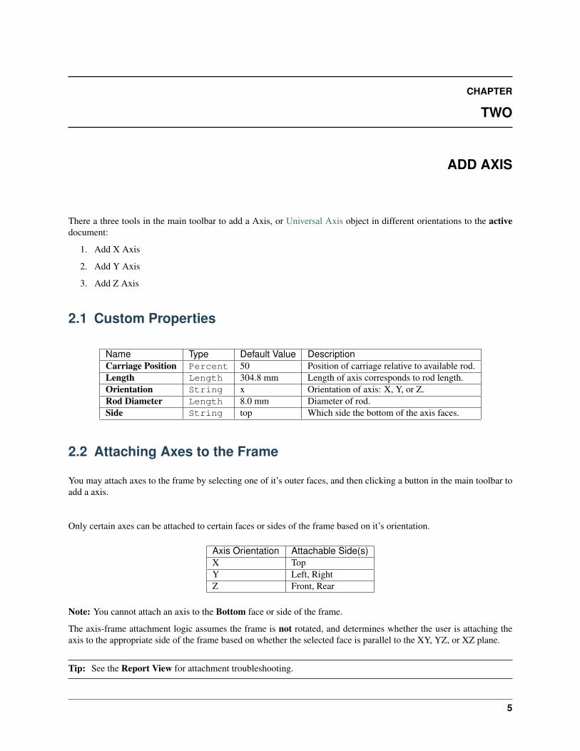
ADD AXIS
There a three tools in the main toolbar to add a Axis, or Universal Axis object in different orientations to the activedocument:
1. Add X Axis
2. Add Y Axis
3. Add Z Axis
2.1 Custom Properties
Name Type Default Value DescriptionCarriage Position Percent 50 Position of carriage relative to available rod.Length Length 304.8 mm Length of axis corresponds to rod length.Orientation String x Orientation of axis: X, Y, or Z.Rod Diameter Length 8.0 mm Diameter of rod.Side String top Which side the bottom of the axis faces.
2.2 Attaching Axes to the Frame
You may attach axes to the frame by selecting one of it’s outer faces, and then clicking a button in the main toolbar toadd a axis.
Only certain axes can be attached to certain faces or sides of the frame based on it’s orientation.
Axis Orientation Attachable Side(s)X TopY Left, RightZ Front, Rear
Note: You cannot attach an axis to the Bottom face or side of the frame.
The axis-frame attachment logic assumes the frame is not rotated, and determines whether the user is attaching theaxis to the appropriate side of the frame based on whether the selected face is parallel to the XY, YZ, or XZ plane.
Tip: See the Report View for attachment troubleshooting.
5

OSE 3D Printer Workbench, Release 0.1.0
6 Chapter 2. Add Axis

CHAPTER
THREE
ADD HEATED BED
The Add Heated Bed tool adds a heated bed to the active document.
3.1 Custom Properties
Name Type Default Value DescriptionSize Length 203.2 mm Size or dimension of heated bed.
3.2 Centering Heated Bed to Frame & Elevating to Z Axes
1. Hold-down Ctrl key for selecting multiple objects
2. Select one Z axis
3. Select the Frame
4. Click the Add Heated Bed button on the main toolbar
3.3 See Also
• D3D Heated Bed
• Heated Bed
7

OSE 3D Printer Workbench, Release 0.1.0
8 Chapter 3. Add Heated Bed

CHAPTER
FOUR
ADD EXTRUDER
The Add Extruder tool adds an extruder to the active document.
4.1 Attaching Extruder to X Axis Carriage
An extruder can be attached to the carriage of the top X axis by selecting the top face of the carriage, and then clickingthe Add Extruder button in the main toolbar.
4.2 See Also
• D3D Extruder
• File:Simpleextruderassy.fcstd
• File:Finalextruder.png
9

OSE 3D Printer Workbench, Release 0.1.0
10 Chapter 4. Add Extruder

CHAPTER
FIVE
GENERATE CUT LIST
There are two options in the main menu to generate a cut list:
1. Copy Cut List to Clipboard
2. Save Cut List as CSV
Both options generate a cut list with the following:
• Rods for axes, heated bed, and spool holder
• Angled bars to construct a frame with 3d printable corners
5.1 How it Works
Each option queries the active document for Axis objects and the Frame object in order to determine the rods andangled bars for the cut list.
5.1.1 Determining Rod Quantity
• 2 X Axis Rods are added for every X Axis object
• 2 Y Axis Rods are added or every Y Axis object
• 2 Z Axis Rods are added for every Z Axis object
• 3 Spool Holder Rods are added based on the existence of a Frame object
• 2 Heated Bed Rods are added for every pair of Z Axis objects
5.1.2 Determining Rod Length
• X Axis Rod Length is adjusted by adding 4 inches
• Y Axis Rod Length corresponds with Length of the axis in the document
• Z Axis Rod Length is adjusted by subtracting 1 inch
• Length of Heated Bed Rods and 1 Spool Holder Rod are equal to the length of the Frame
• Length of 2 Spool Holder Rods are equal to the length of the Frame minus 1 inch (similar to Z axis rods)
11

OSE 3D Printer Workbench, Release 0.1.0
5.1.3 Determining Angled Bar Quantity
• 12 Angled Bars are added based on the existence of a Frame object
5.1.4 Determining Angled Bar Length
Angled bar length is calculated from the following formula:
Frame.Size - ((Frame.Width + (Frame.Thickness * 2)) * 2)
For example, a 12 in frame with a 1.5 in Width and 0.125 in Thickness could have 8.5 in angled bars.
12 in - ((1.5 in + (0.125 in * 2)) * 2) = 8.5 in
12 Chapter 5. Generate Cut List

CHAPTER
SIX
MAKE ANGLE FRAME CONNECTOR
The Make Angle Frame Connector tool makes a 3D-printable Angle Frame Connector with the specified parametersentered from the Task Panel.
6.1 Parameters
Slot Width Width of three inner slots.
Slot Thickness Thickness of three inner slots.
Orientation One of eight possible corners of the frame.
Add Set Screw Whether to add a set screw mechanism.
Useful for larger frames when worried about slips or frame mis-alignment.
13

OSE 3D Printer Workbench, Release 0.1.0
Attention: Assumes M6 set-screw and nut.
Add Filleting Whether to round edges of three inner slots.
Tip: Makes inserting angled bars later a little easier.
6.2 See Also
• FreeCAD Wiki - Export to STL or OBJ
14 Chapter 6. Make Angle Frame Connector

CHAPTER
SEVEN
INCLUDING MOVE AND ROTATE TOOLS
This document covers how to include the Move and Rotate functions of the Draft Workbench.
1. Load the Draft Workbench by selecting it from the workbench dropdown.
2. Select Tools, and then Customize from the Main menu.
3. Next, select the Toolbars tab.
15

OSE 3D Printer Workbench, Release 0.1.0
4. Select OSE 3D Printer from the dropdown in the right pane.
5. Click the New. . . button.
6. Name the toolbar Move + Rotate, and click OK.
7. Select the Draft workbench from the dropdown in the left pane.
8. Find the Move and Rotate tools and use the Move right button, or right arrow to add them to the Move +Rotate toolbar.
16 Chapter 7. Including Move and Rotate Tools

OSE 3D Printer Workbench, Release 0.1.0
9. You should now have the Move and Rotate tools alongside the OSE 3D Printer tools.
See Also
Customize Toolbars on the FreeCAD Wiki.
17

OSE 3D Printer Workbench, Release 0.1.0
18 Chapter 7. Including Move and Rotate Tools

CHAPTER
EIGHT
OSE3DPRINTER
ose3dprinter library package containing code related to the geometry parts.
The ose3dprinter package is:
• Independent of the freecad.ose3dprinter package
• Must not know about the FreeCAD GUI (i.e. FreeCADGui or Gui)
• Executable from a server and command-line context
8.1 ose3dprinter.attachment
Attachment functions to make 3D Printer parts appear attached to each other.
Name Descriptionget_axis_frame_attachment_kwargs Get a dictionary describing how to attach an axis to a frame.get_default_axis_creation_kwargs Get default kwargs to create an axis with when not attaching
to a frame.get_extruder_axis_attachment_kwargs Get a dictionary describing how to attach an extruder to an
axis.get_heated_bed_frame_axis_attachment_kwargsGet a dictionary describing how to attach a heated bed to a
frame and axis.
get_axis_frame_attachment_kwargs(frame, selected_frame_face, axis_orientation)Get a dictionary describing how to attach an axis to a frame.
Keys include length, placement, and origin translation offset for making an axis object appear attached to aselected frame face.
Parameters
• frame – Frame object to attach axis to.
• selected_frame_face (Part.Face) – Selected face of frame to attach axis to.
• axis_orientation (str) – Orientation of axis.
Returns Dictionary describing how to attach an axis to a frame.
Return type dict
get_default_axis_creation_kwargs(axis_orientation)Get default kwargs to create an axis with when not attaching to a frame.
19

OSE 3D Printer Workbench, Release 0.1.0
Parameters axis_orientation (str) – Orientation of axis.
Returns Default kwargs to create an axis with when not attaching to a frame.
Return type dict
get_extruder_axis_attachment_kwargs(axis, selected_axis_face)Get a dictionary describing how to attach an extruder to an axis.
Parameters
• axis – Axis object to attach extruder to.
• selected_axis_face (Part.Face) – Selected face of axis to attach extruder to.
Returns Dictionary describing how to attach an extruder to an axis.
Return type dict
get_heated_bed_frame_axis_attachment_kwargs(frame, axis)Get a dictionary describing how to attach a heated bed to a frame and axis.
Parameters
• frame – Frame object to attach heated bed to.
• axis – Axis object to attach heated bed to.
Returns Dictionary describing how to attach a heated bed to a frame and axis.
Return type dict
8.2 ose3dprinter.model
Models for 3D Printer parts.
Name DescriptionAxisModel Encapsulates the data (i.e. topography and shape) for a Axis,ExtruderModel Encapsulates the data (i.e. topography and shape) for a Extruder,FrameModel Encapsulates the data (i.e. topography and shape) for a Frame,HeatedBedModel Encapsulates the data (i.e. topography and shape) for a Heated Bed,
class AxisModel(obj, length=304.8, carriage_position=50, orientation='x', side='top',placement=Placement [Pos=(0,0,0), Yaw-Pitch-Roll=(0,0,0)], ori-gin_translation_offset=Vector (0.0, 0.0, 0.0))
Bases: osecore.app.model.Model
Encapsulates the data (i.e. topography and shape) for a Axis, and is separate from the “view” or GUI represen-tation.
Name Type Default Value DescriptionCarriage Position Percent 50 Position of carriage relative to available rod.Length Length 304.8 mm Length of axis corresponds to rod length.Orientation String x Orientation of axis: X, Y, or Z.Rod Diameter Length 8.0 mm Diameter of rod.Side String top Which side the bottom of the axis faces.
20 Chapter 8. ose3dprinter

OSE 3D Printer Workbench, Release 0.1.0
Type = 'OSEAxis'
calculate_carriage_box_x()
calculate_top_of_carriage_box_for_z_axis()
execute(obj)Execute on document recompute.
is_x()Return whether or not this axis is a X axis.
This assumes the axis is parallel to the XY, YZ, or XZ planes, and not rotated in a weird diagonal orskewed way.
Returns Whether this axis is a X axis.
Return type bool
is_y()Return whether or not this axis is a Y axis.
This assumes the axis is parallel to the XY, YZ, or XZ planes, and not rotated in a weird diagonal orskewed way.
Returns Whether this axis is a Y axis.
Return type bool
is_z()Return whether or not this axis is a Z axis.
This assumes the axis is parallel to the XY, YZ, or XZ planes, and not rotated in a weird diagonal orskewed way.
Returns Whether this axis is a Z axis.
Return type bool
class ExtruderModel(obj, placement=Placement [Pos=(0,0,0), Yaw-Pitch-Roll=(0,0,0)], ori-gin_translation_offset=Vector (0.0, 0.0, 0.0))
Bases: osecore.app.model.Model
Encapsulates the data (i.e. topography and shape) for a Extruder, and is separate from the “view” or GUIrepresentation.
Based on: https://wiki.opensourceecology.org/wiki/File:Simpleextruderassy.fcstd
See: https://wiki.opensourceecology.org/wiki/File:Finalextruder.png
Name Type Default Value Description
Type = 'OSEExtruder'
execute(obj)Execute on document recompute.
class FrameModel(obj, size=304.8, width=38.1, thickness=3.175, has_corners=False,placement=Placement [Pos=(0,0,0), Yaw-Pitch-Roll=(0,0,0)], ori-gin_translation_offset=Vector (0.0, 0.0, 0.0))
Bases: osecore.app.model.Model
Encapsulates the data (i.e. topography and shape) for a Frame, and is separate from the “view” or GUI repre-sentation.
8.2. ose3dprinter.model 21
OSE 3D Printer Workbench, Release 0.1.0
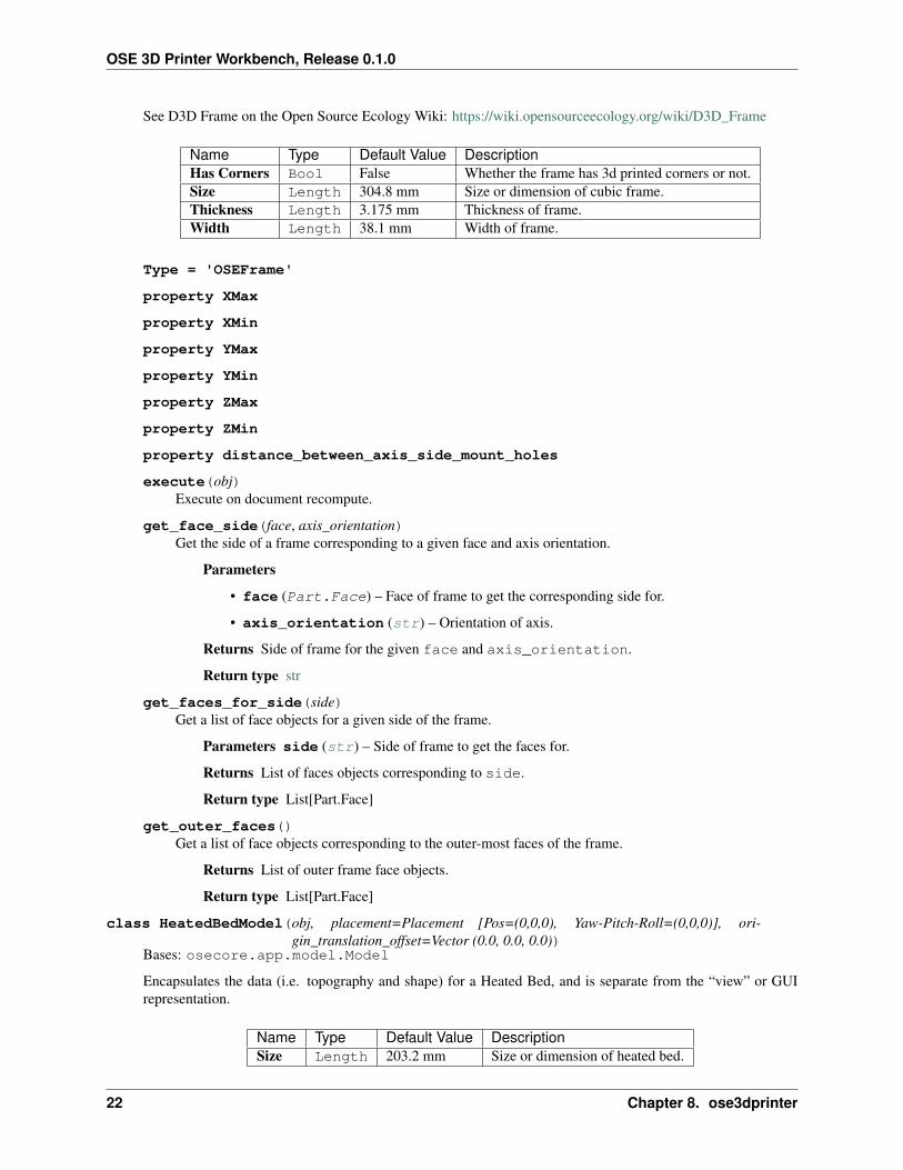
See D3D Frame on the Open Source Ecology Wiki: https://wiki.opensourceecology.org/wiki/D3D_Frame
Name Type Default Value DescriptionHas Corners Bool False Whether the frame has 3d printed corners or not.Size Length 304.8 mm Size or dimension of cubic frame.Thickness Length 3.175 mm Thickness of frame.Width Length 38.1 mm Width of frame.
Type = 'OSEFrame'
property XMax
property XMin
property YMax
property YMin
property ZMax
property ZMin
property distance_between_axis_side_mount_holes
execute(obj)Execute on document recompute.
get_face_side(face, axis_orientation)Get the side of a frame corresponding to a given face and axis orientation.
Parameters
• face (Part.Face) – Face of frame to get the corresponding side for.
• axis_orientation (str) – Orientation of axis.
Returns Side of frame for the given face and axis_orientation.
Return type str
get_faces_for_side(side)Get a list of face objects for a given side of the frame.
Parameters side (str) – Side of frame to get the faces for.
Returns List of faces objects corresponding to side.
Return type List[Part.Face]
get_outer_faces()Get a list of face objects corresponding to the outer-most faces of the frame.
Returns List of outer frame face objects.
Return type List[Part.Face]
class HeatedBedModel(obj, placement=Placement [Pos=(0,0,0), Yaw-Pitch-Roll=(0,0,0)], ori-gin_translation_offset=Vector (0.0, 0.0, 0.0))
Bases: osecore.app.model.Model
Encapsulates the data (i.e. topography and shape) for a Heated Bed, and is separate from the “view” or GUIrepresentation.
Name Type Default Value DescriptionSize Length 203.2 mm Size or dimension of heated bed.
22 Chapter 8. ose3dprinter

OSE 3D Printer Workbench, Release 0.1.0
Type = 'OSEHeatedBed'
execute(obj)Execute on document recompute.
8.3 ose3dprinter.part
Parts for 3D Printer.
Name DescriptionAngleFrameConnector Connects angled bars together in a cubic frame.AngledBarFrame Frame made from 12 angled bars connected by angle frame connectors.Axis Modular and scalable CNC axis for creating cartesian CNC machines.CNCCutFrame Frame made from flat sheets cut by a CNC machine.Extruder Extruder for extruding heated-plastic.HeatedBed Heated bed to help prevent warping of prints.
class AngleFrameConnectorBases: object
Connects angled bars together in a cubic frame.
An angle frame connector is made up of three brackets.
axis_side_mount_length = 27.75
axis_side_mount_width = 5
classmethod calculate_bracket_length(width, thickness)Calculate the length of the bracket.
Parameters
• width (float) – Width of the angled frame.
• thickness (float) – Thickness of the angled frame.
Returns Length of one of the three brackets that make up an angle frame connector.
Return type float
classmethod calculate_y_axis_overhang_distance()Calculate distance of y axis over-hang.
Returns Distance of y axis over-hang.
Return type float
8.3. ose3dprinter.part 23

OSE 3D Printer Workbench, Release 0.1.0
classmethod distance_between_axis_side_mount_holes_and_frame()Calculate distance between the axis side mount holes and frame.
Returns Distance between the axis side mount holes and frame.
Return type float
classmethod make(width=38.1, thickness=3.175, corner='bottom_left_front',with_set_screw=False, with_filleting=False)
Make an angle frame connector.
Parameters
• width (float) – Width of the angled frame.
• thickness (float) – Thickness of the angled frame.
• corner (str) – Which corner to orient the angle frame connector to. Defaults to bottomleft front corner.
• with_set_screw (bool) – Whether to include set screw mechanism.
• with_filleting (bool) – Whether to include filleting.
Returns Angle frame connector object.
Return type Part.Solid
class AngledBarFrameBases: object
Frame made from 12 angled bars connected by angle frame connectors.
static make(side=304.8, width=38.1, thickness=3.175)Make a frame from from 12 angled bars connected by angle frame connectors.
No welding or epoxy required, and the frame can be disassembled.
Parameters
• side (float) – Side or dimension of frame from one corner to the opposite corner.
• width (float) – Width of angled bar.
• thickness (float) – Thickness of each angled bar.
Returns A frame made up of angled bars, connected by angle frame connectors.
Return type Part.Shape
class AxisBases: object
Modular and scalable CNC axis for creating cartesian CNC machines.
24 Chapter 8. ose3dprinter

OSE 3D Printer Workbench, Release 0.1.0
classmethod calculate_carriage_box_x(rod_length, carriage_position)Calculate x position of carriage box.
Below is an ASCII depiction of a top-side view of an axis.
x position of carriage box
<-------------------->
+---------+ +------+ +---+| | | | | || O O +--------+ +--------+ O || | | | | || O O +--------+ +--------+ O || | | | | |+---------+ +------+ +---+
motor-side carriage box idler
Parameters
• rod_length (float) – Length of axis rods.
• carriage_position (int) – Position of carriage (0 - 100).
Returns X position of carriage box.
Return type float
carriage_box_width = 52
distance_between_hole_and_inner_motor_side = 12.59
distance_between_holes = 22.44
classmethod distance_between_idler_side_holes_and_outer_edge()Calculate distance between idler side holes and outer edge.
Below is an ASCII depiction of a top-side view of the idler-side of an axis.
| || |
+--+---+--+| | ^| O O | || | | distance+---------+ |outer edge v
Returns Distance between idler side holes and outer edge.
8.3. ose3dprinter.part 25

OSE 3D Printer Workbench, Release 0.1.0
Return type float
classmethod distance_between_inner_motor_side_holes_and_outer_edge()Calculate distance between inner motor side holes and outer edge.
Below is an ASCII depiction of a top-side view of the motor-side of an axis.
outer edge ^+---------+ || | || O O | | distance| | |
inner | O O | |holes | | v
+--+---+--+| || |
Returns Distance between inner motor side holes and outer edge.
Return type float
hole_radius = 3.39
idler_box_length = 66
idler_box_width = 26
classmethod make(rod_length=304.8, rod_radius=4.0, carriage_position=50, orienta-tion='x', side='top', initial_placement=Placement [Pos=(0,0,0), Yaw-Pitch-Roll=(0,0,0)], origin_translation_offset=Vector (0.0, 0.0, 0.0))
Make a universal CNC axis.
Parameters
• rod_length (float) – Length of rods.
• rod_radius (float) – Radius of rods.
• carriage_position (int) – Position of carriage as percentage (0 - 100).
• orientation (str) – Default orientation of axis (x, y, or z).
• side (str) – Default side axis faces.
• initial_placement (Base.Placement) – Initial placement for part.
• origin_translation_offset (Base.Vector) – Offset part from origin.
Returns Axis object.
Return type Part.Compound
motor_box_width = 59.5
x_distance_between_holes = 23.36
class CNCCutFrameBases: object
Frame made from flat sheets cut by a CNC machine.
26 Chapter 8. ose3dprinter

OSE 3D Printer Workbench, Release 0.1.0
static make(side=304.8, width=38.1, sheet_thickness=3.175)Make a frame from flat sheets cut by a CNC machine.
These flat sheets are then welded or epoxied together.
This approach works best with welding.
See Also: https://wiki.opensourceecology.org/wiki/D3D_Frame
Parameters
• side (float) – Dimension of one side of a cubic sheet.
• width (float) – Width of outer sheet, after an inner sheet is cut out of the center.
• sheet_thickness (float) – Thickness of each sheet.
Returns A frame “welded” together from eight CNC cut sheets.
Return type Part.Shape
class ExtruderBases: object
Extruder for extruding heated-plastic.
static make(initial_placement=Placement [Pos=(0,0,0), Yaw-Pitch-Roll=(0,0,0)], ori-gin_translation_offset=Vector (0.0, 0.0, 0.0))
Make an extruder.
Parameters
• initial_placement (Base.Placement) – Initial placement for part.
• origin_translation_offset (Base.Vector) – Offset part from origin.
Returns Extruder object.
class HeatedBedBases: object
Heated bed to help prevent warping of prints.
8.3. ose3dprinter.part 27

OSE 3D Printer Workbench, Release 0.1.0
See Also:
• https://wiki.opensourceecology.org/wiki/Heated_Bed
• https://reprap.org/wiki/Heated_Bed
static make(size=203.2, initial_placement=Placement [Pos=(0,0,0), Yaw-Pitch-Roll=(0,0,0)], ori-gin_translation_offset=Vector (0.0, 0.0, 0.0))
Make heated bed.
Parameters
• size (float) – [description]
• initial_placement (Base.Placement) – Initial placement for part.
• origin_translation_offset (Base.Vector) – Offset part from origin.
Returns Heated bed object.
Return type Part.Compound
28 Chapter 8. ose3dprinter

CHAPTER
NINE
FREECAD.OSE3DPRINTER
9.1 freecad.ose3dprinter.command
Commands users can perform in FreeCAD’s GUI.
Name DescriptionAddExtruderCommand Command to add extruder object.AddFrameCommand Command to add Frame object.AddHeatedBedCommand Command to add Heated Bed object.AddXAxisCommand Command to add X Axis object.AddYAxisCommand Command to add Y Axis object.AddZAxisCommand Command to add Z Axis object.CopyCutListToClipboardCommand Command to copy cut-list to clipboard.MakeAngleFrameConnectorCommand Command to make an Angle Frame Connector.SaveCutListAsCsvCommand Command to save cut-list as a CSV file.
class AddExtruderCommandBases: object
Command to add extruder object.
Activated()
GetResources()
IsActive()
NAME = 'AddExtruder'
class AddFrameCommandBases: object
Command to add Frame object.
Activated()
GetResources()
IsActive()
NAME = 'AddFrame'
class AddHeatedBedCommandBases: object
Command to add Heated Bed object.
29

OSE 3D Printer Workbench, Release 0.1.0
Activated()
GetResources()
IsActive()
NAME = 'AddHeatedBed'
class AddXAxisCommandBases: object
Command to add X Axis object.
Activated()
GetResources()
IsActive()
NAME = 'AddXAxis'
class AddYAxisCommandBases: object
Command to add Y Axis object.
Activated()
GetResources()
IsActive()
NAME = 'AddYAxis'
class AddZAxisCommandBases: object
Command to add Z Axis object.
Activated()
GetResources()
IsActive()
NAME = 'AddZAxis'
class CopyCutListToClipboardCommandBases: object
Command to copy cut-list to clipboard.
Activated()
GetResources()
IsActive()
NAME = 'CopyCutListToClipboard'
class MakeAngleFrameConnectorCommandBases: object
Command to make an Angle Frame Connector.
Activated()
GetResources()
IsActive()
30 Chapter 9. freecad.ose3dprinter

OSE 3D Printer Workbench, Release 0.1.0
NAME = 'MakeAngleFrameConnector'
class SaveCutListAsCsvCommandBases: object
Command to save cut-list as a CSV file.
Activated()
GetResources()
IsActive()
NAME = 'SaveCutListAsCsv'
9.2 freecad.ose3dprinter.icon
Package containing icons.
Name Descriptionget_icon_path Get the path to a given icon.
9.2.1 Icons
Icon FilenameExtruder.svgFrame.svgHeatedBed.svgStd_CoordinateSystem.svgXAxis.svgYAxis.svgZAxis.svgdocument-save-as.svgedit-copy.svg
get_icon_path(icon_filename)Get the path to a given icon.
Parameters icon_filename (str) – icon filename (e.g. Box.svg)
Returns Path to icon file.
Return type str
9.2. freecad.ose3dprinter.icon 31

OSE 3D Printer Workbench, Release 0.1.0
9.3 freecad.ose3dprinter.part_feature
Exposes functions to create Part::FeaturePython objects.
Minimally, these objects are custom, parameteric, and have a Shape for viewing in three dimensions.
See Also: https://wiki.freecadweb.org/FeaturePython_Objects https://wiki.freecadweb.org/Creating_a_FeaturePython_Box,_Part_II https://wiki.freecadweb.org/Scripted_objects
Additionally, they may have a ViewProvider class for providing additional customization to their 3d representation,and how they respond to certain graphical interactions such as selection.
See Also: https://wiki.freecadweb.org/Viewprovider
Name Descriptioncreate_axis Creates a axis object with the given name,create_extruder Creates a extruder object with the given name,create_frame Creates a frame object with the given name,create_heated_bed Creates a heated bed object with the given name,
create_axis(document, name, length=304.8, carriage_position=50, orientation='x', side='top', place-ment=Placement [Pos=(0,0,0), Yaw-Pitch-Roll=(0,0,0)], origin_translation_offset=Vector(0.0, 0.0, 0.0))
Creates a axis object with the given name, and adds it to the document.
create_extruder(document, name, placement=Placement [Pos=(0,0,0), Yaw-Pitch-Roll=(0,0,0)], ori-gin_translation_offset=Vector (0.0, 0.0, 0.0))
Creates a extruder object with the given name, and adds it to the document.
create_frame(document, name)Creates a frame object with the given name, and adds it to the document.
create_heated_bed(document, name, placement=Placement [Pos=(0,0,0), Yaw-Pitch-Roll=(0,0,0)], ori-gin_translation_offset=Vector (0.0, 0.0, 0.0))
Creates a heated bed object with the given name, and adds it to the document.
9.4 OSE_3D_Printer
Command Registry Module
Name Descriptionregister_commands Register all workbench commands,
register_commands()Register all workbench commands, and associate them to toolbars, menus, sub-menus, and context menu.
32 Chapter 9. freecad.ose3dprinter

OSE 3D Printer Workbench, Release 0.1.0
9.5 init_gui
Imported when FreeCAD starts up to add workbench to GUI.
9.5. init_gui 33

OSE 3D Printer Workbench, Release 0.1.0
34 Chapter 9. freecad.ose3dprinter

CHAPTER
TEN
INDICES AND TABLES
• genindex
• modindex
• search
35

OSE 3D Printer Workbench, Release 0.1.0
36 Chapter 10. Indices and tables

PYTHON MODULE INDEX
ffreecad.ose3dprinter, 29freecad.ose3dprinter.command, 29freecad.ose3dprinter.icon, 31freecad.ose3dprinter.init_gui, 33freecad.ose3dprinter.OSE_3D_Printer, 32freecad.ose3dprinter.part_feature, 32
oose3dprinter, 19ose3dprinter.attachment, 19ose3dprinter.model, 20ose3dprinter.part, 23
37

OSE 3D Printer Workbench, Release 0.1.0
38 Python Module Index
INDEX
AActivated() (AddExtruderCommand method), 29Activated() (AddFrameCommand method), 29Activated() (AddHeatedBedCommand method), 29Activated() (AddXAxisCommand method), 30Activated() (AddYAxisCommand method), 30Activated() (AddZAxisCommand method), 30Activated() (CopyCutListToClipboardCommand
method), 30Activated() (MakeAngleFrameConnectorCommand
method), 30Activated() (SaveCutListAsCsvCommand method),
31AddExtruderCommand (class in
freecad.ose3dprinter.command), 29AddFrameCommand (class in
freecad.ose3dprinter.command), 29AddHeatedBedCommand (class in
freecad.ose3dprinter.command), 29AddXAxisCommand (class in
freecad.ose3dprinter.command), 30AddYAxisCommand (class in
freecad.ose3dprinter.command), 30AddZAxisCommand (class in
freecad.ose3dprinter.command), 30AngledBarFrame (class in ose3dprinter.part), 24AngleFrameConnector (class in ose3dprinter.part),
23Axis (class in ose3dprinter.part), 24axis_side_mount_length (AngleFrameConnector
attribute), 23axis_side_mount_width (AngleFrameConnector
attribute), 23AxisModel (class in ose3dprinter.model), 20
Ccalculate_bracket_length() (AngleFrame-
Connector class method), 23calculate_carriage_box_x() (Axis class
method), 25calculate_carriage_box_x() (AxisModel
method), 21
calculate_top_of_carriage_box_for_z_axis()(AxisModel method), 21
calculate_y_axis_overhang_distance()(AngleFrameConnector class method), 23
carriage_box_width (Axis attribute), 25CNCCutFrame (class in ose3dprinter.part), 26CopyCutListToClipboardCommand (class in
freecad.ose3dprinter.command), 30create_axis() (in module
freecad.ose3dprinter.part_feature), 32create_extruder() (in module
freecad.ose3dprinter.part_feature), 32create_frame() (in module
freecad.ose3dprinter.part_feature), 32create_heated_bed() (in module
freecad.ose3dprinter.part_feature), 32
Ddistance_between_axis_side_mount_holes()
(FrameModel property), 22distance_between_axis_side_mount_holes_and_frame()
(AngleFrameConnector class method), 23distance_between_hole_and_inner_motor_side
(Axis attribute), 25distance_between_holes (Axis attribute), 25distance_between_idler_side_holes_and_outer_edge()
(Axis class method), 25distance_between_inner_motor_side_holes_and_outer_edge()
(Axis class method), 26
Eexecute() (AxisModel method), 21execute() (ExtruderModel method), 21execute() (FrameModel method), 22execute() (HeatedBedModel method), 23Extruder (class in ose3dprinter.part), 27ExtruderModel (class in ose3dprinter.model), 21
FFrameModel (class in ose3dprinter.model), 21freecad.ose3dprinter
module, 29
39

OSE 3D Printer Workbench, Release 0.1.0
freecad.ose3dprinter.commandmodule, 29
freecad.ose3dprinter.iconmodule, 31
freecad.ose3dprinter.init_guimodule, 33
freecad.ose3dprinter.OSE_3D_Printermodule, 32
freecad.ose3dprinter.part_featuremodule, 32
Gget_axis_frame_attachment_kwargs() (in
module ose3dprinter.attachment), 19get_default_axis_creation_kwargs() (in
module ose3dprinter.attachment), 19get_extruder_axis_attachment_kwargs()
(in module ose3dprinter.attachment), 20get_face_side() (FrameModel method), 22get_faces_for_side() (FrameModel method), 22get_heated_bed_frame_axis_attachment_kwargs()
(in module ose3dprinter.attachment), 20get_icon_path() (in module
freecad.ose3dprinter.icon), 31get_outer_faces() (FrameModel method), 22GetResources() (AddExtruderCommand method),
29GetResources() (AddFrameCommand method), 29GetResources() (AddHeatedBedCommand method),
30GetResources() (AddXAxisCommand method), 30GetResources() (AddYAxisCommand method), 30GetResources() (AddZAxisCommand method), 30GetResources() (CopyCutListToClipboardCom-
mand method), 30GetResources() (MakeAngleFrameConnectorCom-
mand method), 30GetResources() (SaveCutListAsCsvCommand
method), 31
HHeatedBed (class in ose3dprinter.part), 27HeatedBedModel (class in ose3dprinter.model), 22hole_radius (Axis attribute), 26
Iidler_box_length (Axis attribute), 26idler_box_width (Axis attribute), 26is_x() (AxisModel method), 21is_y() (AxisModel method), 21is_z() (AxisModel method), 21IsActive() (AddExtruderCommand method), 29IsActive() (AddFrameCommand method), 29IsActive() (AddHeatedBedCommand method), 30
IsActive() (AddXAxisCommand method), 30IsActive() (AddYAxisCommand method), 30IsActive() (AddZAxisCommand method), 30IsActive() (CopyCutListToClipboardCommand
method), 30IsActive() (MakeAngleFrameConnectorCommand
method), 30IsActive() (SaveCutListAsCsvCommand method), 31
Mmake() (AngledBarFrame static method), 24make() (AngleFrameConnector class method), 24make() (Axis class method), 26make() (CNCCutFrame static method), 27make() (Extruder static method), 27make() (HeatedBed static method), 28MakeAngleFrameConnectorCommand (class in
freecad.ose3dprinter.command), 30module
freecad.ose3dprinter, 29freecad.ose3dprinter.command, 29freecad.ose3dprinter.icon, 31freecad.ose3dprinter.init_gui, 33freecad.ose3dprinter.OSE_3D_Printer,
32freecad.ose3dprinter.part_feature,
32ose3dprinter, 19ose3dprinter.attachment, 19ose3dprinter.model, 20ose3dprinter.part, 23
motor_box_width (Axis attribute), 26
NNAME (AddExtruderCommand attribute), 29NAME (AddFrameCommand attribute), 29NAME (AddHeatedBedCommand attribute), 30NAME (AddXAxisCommand attribute), 30NAME (AddYAxisCommand attribute), 30NAME (AddZAxisCommand attribute), 30NAME (CopyCutListToClipboardCommand attribute), 30NAME (MakeAngleFrameConnectorCommand attribute),
30NAME (SaveCutListAsCsvCommand attribute), 31
Oose3dprinter
module, 19ose3dprinter.attachment
module, 19ose3dprinter.model
module, 20ose3dprinter.part
module, 23
40 Index

OSE 3D Printer Workbench, Release 0.1.0
Rregister_commands() (in module
freecad.ose3dprinter.OSE_3D_Printer), 32
SSaveCutListAsCsvCommand (class in
freecad.ose3dprinter.command), 31
TType (AxisModel attribute), 20Type (ExtruderModel attribute), 21Type (FrameModel attribute), 22Type (HeatedBedModel attribute), 23
Xx_distance_between_holes (Axis attribute), 26XMax() (FrameModel property), 22XMin() (FrameModel property), 22
YYMax() (FrameModel property), 22YMin() (FrameModel property), 22
ZZMax() (FrameModel property), 22ZMin() (FrameModel property), 22
Index 41


