Date post: | 10-Apr-2018 |
Category: |
Documents |
Upload: | bob-andrepont |
View: | 218 times |
Download: | 0 times |
8/8/2019 OSO-I Press Kit
http://slidepdf.com/reader/full/oso-i-press-kit 1/27
.- - s/o
1.N"
National Aeronautics andSpace Administration
Washington. D.C. 20546AC-202 755-8370
For Release:
IMMEDTATE
PRESS KIT PROJECT: OSO-I
RELEASE NO: 75-158 Contents
GENERAL RELEASE .................. * * ... * .. . 1-7
OSO PROGRAM RESULTS ............** * *** ......... g 8
ORBITING SOLAR OBSERVATORY-I...........R......... 9-11
OSO-I SAIL EXPERIMENTS ............. i.......**.2-13
OSO-I WHEEL EXPERIMENTS ...................... ... 14-17
DELTA LAUNCH VEHICLE......H. . . . .. ... .. ... . ..... 18
STRAIGHT-EIGHT DELTA FACTS AND FIGURES........... 19
MAJOR DELTA/OSO-I FLIGHT EVENTS.................. 20
TRACKING AND DATA ACQUISITION.................... 21
PROGRAM OFFICIALS ................. oo. .o.o. .o. . 22-23
CONTRACTORS .................... 23
8/8/2019 OSO-I Press Kit
http://slidepdf.com/reader/full/oso-i-press-kit 2/27
7-. so - - - i- .
National Aeronautics andSpace Administration
Washington. D.C. 20546AC 202 755-8370
James Kukowski 2TEHeadquarters, Washington, D.C.(Phone: 202/755-8347)
Joe McRobertsGoddard Space Flight Center, Greenbelt, Md.(Phone: 301/982-4955)
RELEASE NO: 75-158
SOPHISTICATED ORBITING SOLAR OBSERVATORY TO BE.LAUNCHED
A better understanding of energy transfer in the Sun's
hot, gaseous atmosphere and a continuing study of the Sun's
11-year sunspot cycle will be the objectives of NASA's newest
Orbiting Solar Observatory, OSO-I, scheduled to be launched
from Cape Canaveral, Fla., about Junc 19.
Eighth in the series of OSOs, the sophisticated space-
craft will be launched by a Delia rocket into a 553-kilometer
(343-mile) circular orbit.
-more-
June 2, 1975
8/8/2019 OSO-I Press Kit
http://slidepdf.com/reader/full/oso-i-press-kit 3/27
.- - - -
-'n~f m5:EP-- -
L v .1 ;PIN
22
American and French ultraviolet telescopes will be
trained on the Sun to investigate the methods by which
solar energy is transferred between layers of the Sun's
atmosphere. The observation is a follow-up on clues re-
vealed by astronaut-operated solar observation equipment on
Skylab.
In addition, the satellite studies, to be made in the
present minimum phase of the Sun's li-year sunspot cycle, will
determine basic conditions for comparison with intense acti-
vity that astronomers expect to occur on the Sun during 1980-
82, when the sunspot cycle reaches its next predicted peak.
4o
Robert H. Pickard, OSO Project Manage- at Goddard :.:pdce
Flight Center, Greenbelt, Md., which manages the project, stys:
"Although answers to such questions as 'what causes a solar
flare?' or 'what causes the solar cycle?' have not been pro-
vided, we are getting a much better understanding of our
nearest star from the OSO spacecraft."
A sophisticated device called the Atored command pro-
cessor, as well as a small experiment computer, makes OSO
extremely flexible for the user scientist.
- more -
8/8/2019 OSO-I Press Kit
http://slidepdf.com/reader/full/oso-i-press-kit 4/27
i lo,. -*z---- ll
-3-
The stored command processor's flexibility is such,
according to Project Scientist, Dr. Stephen P. Maran, that
"astronomers on the ground can formulate complex observing
instructions in response to changing conditions on the Sun.
The new electronic apparatus on the satellite will execute
these orders at predetermined times."
OSO-I (Eye) is larger and more sophisticated than pre-
vious OSO spacecraft which have observed the Sun over an en-
tire solar cycle since the launch of OSO-1 in March 1962.
OSO-I weighs 1064 kilograms (2346 pounds), compared to OSO-1
which weighed 200 kg (440 lbs.).
In general, our knowledge of solar physics today is
based to a significant degree on discoveries made by the
earlier OSO satellites and by the Apollo Telescope Mount
on Skylab. Space observations allow us to receive, measure
and analyze the Sun's ultraviolet and x-rays, which cannot
penetrate to the surface of Earth due to the screening ef-
fect of our atmosphere.
-more
f
8/8/2019 OSO-I Press Kit
http://slidepdf.com/reader/full/oso-i-press-kit 5/27
g;,7,6.. -,, -
-4-
OSO-I will carry a total of eight experiments includin',
the two principal ultraviolet instruments from the University
of Colorado, and the French Laboratory for Stellar and
Planetary Physics, near Paris. The French instrument is
being provided under a cooperative agreement between NASA
and the Centre Nationals d'Etudes Spatiales (CNES) in which
there is no exchange of funds. The other experiments were
supplied by scientists of Goddard Space Flight Center (two
experiments), Columbia University, in New York; University
of Wisconsin, U.S. Naval Research, Washington, D.C.; and
Lockheed Missiles and Space Company, Palo Alto, Calif.
The spacecraft was built by the Hughes Aircraft Company,
El Segundo, Calif.
A secondary objective of OSO-I is to investigate celes-
tial sources of x-rays in the Milky Way galaxy and beyond.
The most elaborate selection of cosmic x-ray telescopes yet
launched will be .ised to investigate the mysterious x-ray
background radiation that appears to be arriving at the
Earth from all directions in space. Scientists will attempt
to determine conclusively whether the radiation comes from
the nearby surroundings of our Milky Way galaxy or from the
distant reaches of space.
- more -
8/8/2019 OSO-I Press Kit
http://slidepdf.com/reader/full/oso-i-press-kit 6/27
In addition, the x-ray telescopes will be aimed at
more than 102 pre-selected objects of special interest to
astronomers. They will observe supernova remnants (the hot
expanding clouds of cosmic debris that result from the explo-
sive disruption of dying stars) to determine their physical
and chemical composition as well as search for pulsars within
the clouds.
OSO-I will also observe "X-ray binaries" that seem to
consist of a visible star and a small invisible companion,
which may be a highly condensed "neutron star" or possibly a
"black hole". (A black hole is believed to form when a shrink-
ing star's gravitational field intensifies to the point that
no light or matter can ever escape from the object.)
Past experience with the Uhuiu and OSO*-7 satellites
suggests that the more sensitive equipment on OSO-I will
discover new x-ray sources in space, which may prove to be
of even greater interest than those which are already under
study.
-more-
8/8/2019 OSO-I Press Kit
http://slidepdf.com/reader/full/oso-i-press-kit 7/27
-6-
Understanding the Sun is important not only because it
is the ultimate source of energy that supports all life on
Earth, but also because it is the closest nearby star for
astronomers and physicists to study in detail. The Sun is
a laboratory where temperatures, pressures and magnetic field
intensities can be studied at magnitudes impossible to achieve
on Earth. In addition, there is abundant evidence that the
SuIl affects Earth's weather and climate, but the precise mecha-
nism is not clearly understood.
The spacecraft structure consists of a rotating or
spinning base section, called the "wheel" and the upper por-
tion, or "sail". The wheel carries experiments such as the
cosmic x-ray telescopes and associated spacecraft subsystems
not requiring sustained solar pointing. The sail carries
those experiments such as the spectrometers and associated
subsystems that must point continuously at the Sun.
- more -
8/8/2019 OSO-I Press Kit
http://slidepdf.com/reader/full/oso-i-press-kit 8/27
-6A -
The central control room for OSO-I is located at Goddard
Space Flight Center. It is linked electronically to a special
Solar Observing Center at the University of Colorado in Boulder.
There, American and French solar scientists will use computers
and data-display consoles to examine the satellite measure-
ments, monitor ground-based solar observations, ani plan
daily satellite observations.
Principal investigators for the two primary instruments
on OSO-I are Dr. Elmo C. Bruner, University of Colorado, and
Dr. Roger M. Bonnet, Director of the Laboratory for Stellar
and Planetary Physics, a French government organization loca-
ted near Paris. In addition, each is assisted by several co-
investigators and by scientists from about 30 institutions
in the U.S. and abroad (including several from the Soviet
Union) who have been appointed as guest investigators to
share in the analysis of the satellite measurements. In
this way, according to Dr. Adrienne F. Timothy, OSO Program
Scientist at NASA Headquarters, "the widest and promptest
possible use of the solar measurements will be made by quali-
fied scientists."
The OSO-I program is under the overall management of
NASA's Office of Space Science, NASA Headquarters. Project
management for OSO as well as the Delta launch vehicle is
the responsibility of the Goddard Space Flight Center. God-
dard is also responsible for tracking and data acquisition.
- more -
- - * --. dI
8/8/2019 OSO-I Press Kit
http://slidepdf.com/reader/full/oso-i-press-kit 9/27
-7-
Prime contractor for the spacecraft is Hughes Air-
craft Co. McDonnell Douglas, Huntington Beach, Calif.,
builds the Delta.
(END OF PRESS RELEASE/BACKGROUND INFORMATION FOLLOWS)
8/8/2019 OSO-I Press Kit
http://slidepdf.com/reader/full/oso-i-press-kit 10/27
*W7A-
s s| I |
:s
Be
-s-- . a- ^ * as
-- -
-*- HIS, , 0
t 3t Up-
'z
I' an FAct- v\ vA =- Z U tHe-N ---
E-- --
- --
-
-more-ORIGINAL PAGE 1SOF POOR QUAIZA
-
8/8/2019 OSO-I Press Kit
http://slidepdf.com/reader/full/oso-i-press-kit 11/27
-8-
OSO PROGRAM RESULTS
Since OSO-l was placed into Earth orbit on March 7, 1962,significant scientific information has been gathered by thesQlar observatories. Among the discoveries made by scien-tists from studying OSO data are:
* An increase in soft x-ray emissions often precedesan impending solar flare by up to several minutes. (It takes3 1/2 minutes for solar radiation to travel from the Sun toEarth.)
* Solar flares, the sudden release of tremendous energy
and material from the Sun, have temperatures above 30 milliondegrees. (A flare may last minutes or hours and may releaseas much energy as the whole world uses in 100,000 years.)
* Solar polar caps: The poles have temperatures of about1 million degrees Celsius (l.P million degrees F.), comparedto other parts of the solar corona which register about 2 rmil-lion degrees C. (3.6 million F.).
* Coronal holes, where temperatures are much lower thdnaverage coronal temperatures. These holes seem to be distinctfrom the solar polar caps, although they do have many similarcharacteristics. The polar caps and holes may provide new
clues to the Sun's interior.
* Enormous eruptions of material from the Sun's outercorona, events that had not been recognized throughout some100 years of scientific eclipse observations. Similar erup-tions that reshaped solar magnetic fields and coronal struc-ture were observed by SkylaD in 1973 to confirm this discovery.
* The measurement of highly accurate positions forseveral x-ray sources which later permitted them to be iden-tified visually. Such measurements may provide new clues asto whether or not black holes exist.
e High energy gamma rals are coming from a source inthe middle of our galaxy.
- more -
8/8/2019 OSO-I Press Kit
http://slidepdf.com/reader/full/oso-i-press-kit 12/27
-9-
ORBITING SOLAROBSERVATORY-I
OSO-I will be launched into a 553 km (343 mi.) orbit,
inclined 330 to the equator. It will investigate the Sun's
lower corona, the chromosphere, and their interface in the
X-ray and ultraviolet spectral regions to obtain a better
understanding of the transport of energy from the photosphere
into the corona. it will also study Sun/Earth relationships
and background cosmic x-rays.
Spacecraft
The OSO is a spin stabilized spacecraft having a despun
platform to accommodate experiments which point at the Sun or
other celestial source of electromagnetic radiations. Experi-
ments which do not require sustained solar referenced pointing
or which scan the celestial sphere, are accommodated in the
rotating portion. The observatory weighs 1,06A kq (2,346 lbs.)
and has a design lifetime of 12 months.
Structure
The bottom section called the wheel is a cylinder 152.4 cm
(6 0 in.) in diameter by 71.6 cm (28.2 in.) high. The rotating
wheel section accounts for 70 percent of the total spacecraftweight including 252 kg (555 lbs.) for the 6 experiments loca-
ted there.
The upper section of the spacecraft is called the sail.
The nonspinning sail provides power for the spacecraft by means
Of solar cells, and provides a platform that always looks
at the Sun for the two pointed experiments. The sail is 234.7
cm (92.4 in.) high and 209.6 cm (82.5 in.) wide. The two
pointed experiments together, comprise a package approxi-
mately 38 cm (15 in.) square with a length of 145 cm (57 in.)
and a weight of 122 kg (268 lbs.). It is known as the pointed
instrument assembly (PIA).
-more-
-.W
-Imago
8/8/2019 OSO-I Press Kit
http://slidepdf.com/reader/full/oso-i-press-kit 13/27
-9A-
Solar Array
Centre National de la
Recherche Scientifique
(CNRS) Spectrometer
\ I S> , High Resolution
Ultraviolet Spectrometer
>< r (UnivA, of Colorado)
| \ -\ XTHF Antennas
Nitrogen Gas Tanks 1lMappirng X-ray
Heliometer (Lockheed)
-more-
8/8/2019 OSO-I Press Kit
http://slidepdf.com/reader/full/oso-i-press-kit 14/27
- 10
Power and Electrical Subsystem
The power subsystem consists of a solar array, nickel-cadmium storage batteries, and regulation and control cir-cuits to power the experiment instruments and the spacecraftsubsystems. Approximately 110 watts are provided for obser-vatory day operation of experiments and approximately 81 wattsare provided for experiment night operation (60 minutes day and36 minutes night).
The N on P solar cell array powers the observatory duringthe orbit day and charges the batteries for night operation.
The nickel-cadmium batteries power the observatoryduring normal night operation, during peak day loads, andduring launch operations.
Control Subsystem
The Control Subsystem provides for initial acquisitionand stabilization during the orbit day and night operation.A nutation damper is employed to insure proper control andstability.
The wheel spin rate is 6 rpm and is automatically con-trolled by a pneumatic system to +1.0 rpm. The pitch and
roll control of the observatory ARC maintained by independentpneumatic and magnetic torque systems. The spacecraft spinaxis is maintained by command within the limits of 0+40 ofperpendicular to the position of the Sun, using gas Jets andmagnetic torque coils.
The pointing control orients the sail and controls thePIA instruments by independent azimuth and elevation systems.The control system points the PIA in azimuth and elevation toany point on "Che solar disk or will raster over the entire solardisk or any desired portion.
Command Subsystem
The command subsystem is designed to receive on VHFuplink, decode the pulse-code modulated (PCM) message, andexecute commands which control the observatory and experi-ment instruments. The subsystem incorporates a stored commandprocessor (SCP) operating in conjunction with redundant commandmemories which are capable of storing up to 1,360 commandsCommands are stored while the spacecraft Is in view of a groundcommand station, and executed at any desired time in orbit.To verify correctness of commands stored in the memory; the
stored command file is available as a memory dump at 6,400 bitsper second (bps) on the VHF downlink, or at 128 kilobits persecond (kbps) on the S-band downlink.
- more -
';, :t 3 31: fiff~t - c
8/8/2019 OSO-I Press Kit
http://slidepdf.com/reader/full/oso-i-press-kit 15/27
I . I !4
- 11-
Data Handling and Telemetry Subsystem
Two tape recorders, each of two-orbit capacitt, provide
the data storage medium.
Realtime telemetry and command memory data aro available
on the VHF downlink. VHF transmission is via an o i-coverage
eight-element whip antenna array which is shared wit h the
command subsystem. Realtime data at 6.4 kbps and nape recorder
playback data at 128 kbps are available via the S-B nd downlink.S-Band transmission is via an omni-coverage annular ring slot
array located on the periphery of the wheel.
Housekeeping status of the observatory subsyst ms ismonitored by transducers which convert temperature, pressure,current, and other parameters into scaled voltages uitable for
telemetry inputs.
- more -
8/8/2019 OSO-I Press Kit
http://slidepdf.com/reader/full/oso-i-press-kit 16/27
-12-
OSO-I SAIL EXPERIMENTS
High Resolution Ultraviolet Spectrometer
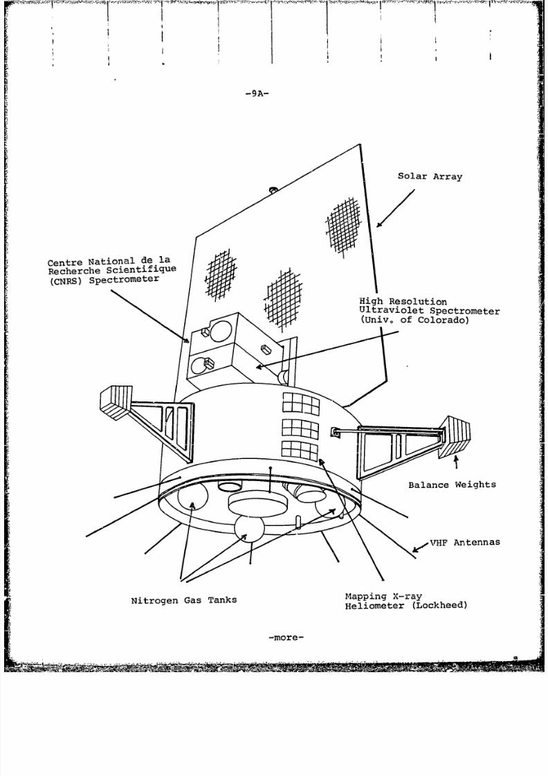
Principal Investigator-Dr. Elmo C. Bruner, Jr.,University of Colorado.
The objectives of this experiment are to measure solarultraviolet line profiles, in the range 1050 to 2300 A, andtheir variation with time and position on the solar disk.Also spectroheliograms*at selected wavelencths will be per-formed which reveal the physical differences between the quietSun and active features such as plages and flares.
The instrument, which is mounted in the OSO sail, consistsof a 1.8 meter (6 feet) extended focal length Cassegrainiantelescope. The spectral resolution of the spectrometer is 0.01 A
The sensors for the spectrometer are two photomultipliertubes, one for the spectral range from 1400 A to 2300 A andanother for wavelengths shorter than 1400 A.
The experiment operational ictodes are controlled by asmall computer within the instrument. This permits flexibilityof observing programs through automated, data dependent, obser-ving sequences.
Chromosphere Fine Structure
Principal Investigator - Dr. R. M. Bonnet, Centre Nationalde la Recherche Scieni:ifique (CNRS), Paris, France.
The objective of this experiment is to observe the solarchromospheric stracture simultaneously in six lines front 1000to 4000 A that originate from different levels in theatmosphere of the Sun. The lines are: H and K of calcium II:H and K of Magnesium II; Lyman Alpha and Lyman Beta of hvdroqen.
The instrument which is mounted on the OSO sail, is com-
posed of a spectrometer and a Cassegrain telescope with a finepointing system. Sunlight enters the Cassegrainian telescopewhich images the solar disk on the entrance slit of tne spec-trometer. Light passes through the slit, is reflected from acollimating mirror onto a plane grating. The diffracted lightfrom the grating is reflected from mirrors into the .ixit slitsof the spectrometer. A total of four photomultiplier tubes andone channeltron are used as sensors behind the exit slits.
*A map of the Sun at a single wavelength.
8/8/2019 OSO-I Press Kit
http://slidepdf.com/reader/full/oso-i-press-kit 17/27
I I I I '-13-
The telescope has an equivalent focal length of three m(10 ft.).The instrument is capable of achieving angular reso-
lutions from lxl arc sec to lx40 arc sec as a function ofentrance slit position. A spectral resolution of 0.02 A isachieved for all wavelengths except Lyman Beta (0.06 A).
Instrument sequencing is controlled by ground command.The sequencer operates in the given mode until new instructionsare issued by ground command or by the stored command processor
on the satellite.
-more-
4>f4; -V>>; /tS4 r w > * ~ s v n s ;m - w ;g w¢eM,;7.
9 y .>,§/',<S4.i o~ e~~ -~'
8/8/2019 OSO-I Press Kit
http://slidepdf.com/reader/full/oso-i-press-kit 18/27
- 14 -
OSO-I WHEEL EXPERIMENTS
High Sensitivity Crystal Spectrometer and Polarimeter.
Pri.ncipal Investigator - Prof. R. Novick, Columbia
University
Objectives of the experiment are to provide a continuous
monitor of the Sun's emission in the 2-8 kev range; to obtain
a complete spectrum of the Sun every 10 seconds during flares;
and to obtain high resolution spectra of many celestial x-ray
sources. In addition, a graphite-crystal focusing x-ray polari-
meter will be used to measure the polarization of x-ray emission
from stellar sources.
The spectrometer makes use of the wheel rotation to scan
through the solar x-ray spectrum. Two large area crystal panels
of graphite are used for reflection. The arrangement chosen
gives the maximum sensitivity to the expected emission lines
of silicon, sulfur, and iron.
Mapping X-ray Heliometer
Principal Investigator - Dr. L. Acton, Lockheed Missiles
and Space Company.
Objectives of this experiment are to obtain measurements
of the location,spectrum, and intensity of intermediate energy
x-rays (in the 2-30 kev energy range) from individual solar
active regions (flaring as well as quiescent active regions
will be studied) and to acquire significant data about extra-
solar x-ray sources.
The instrument consists of three x-ray collimation and
detection systems, a power supply/distribution system and a
data accumulation/readout system. The three x-ray collimators
are identicai in physical size, but have differently oriented
fields of view.
All x-ray detectors in the instrument are sealed propor-
tional counters. The three detector types are of varied sen-
sitivities in order to enable the instrument to respond to awide range of solar conditions.
Data from the three fan beam scans will be combined to
construct a map that gives the location and angular extent (to
the limit permitted by count statistics and the 2 arc minute
resolution) of observed x-ray sources.
- more -
8/8/2019 OSO-I Press Kit
http://slidepdf.com/reader/full/oso-i-press-kit 19/27
I II
-15-
Investigation of Soft X-ray Background Radiation
Principal Investiqator - Prof. W. L. Kraushaar, University of
Wisconsin.
The objective of this experiment is to study the galac-
tic latitude dependence of the x-ray background radiation using
proportional counters with as narrow collimation as practicalin the region of 0.150 to 45 kev. This has important bearings
on the nature of the radiation, including possible cosmologi-
cal implications. Energy resolution will rely largely on selec-
tive window transmission rather than pulse height measurement.
Rather than aiming towards scattered and short exposures for all
parts of the sky, viewing is parallel and antiparallel to the
wheel spin direction so that two single paths across the sky,
galactic pole to galactic plane, are carefully surveyed with
high statistical accuracy in about six months.
Cosmic X-ray Spectroscopy
Principal Investigator - Dr. P. J. Serlemitsos, Goddard Space
Flight Center.
The scientific objectives are to determine the spectra of
sources and the diffuse cosmic x-ray background in the energy
range of 2 to 60 kev, and to determine the intensity variations
and identify possible emission lines of discrete x-ray sources.
An advanced form of proportional counter is employed as
a detector.
One detector complement looks forward along the spin
a-is (and is periodically occulted by the sail and pointed
instrument assembly), and a second detector complement looks
aft, angled slightly outward from the spin axis. Datais
accumulated in a buffer memory over 1-minute periods, sec-
tored in azimuth for the angled detector.
A spin axis pointing program will permit the detectors
to observe both the diffuse background and selected x-ray
sources during the course of the mission.
- more-
. , . s A ge 2 ' " 'v . v i m __ __
8/8/2019 OSO-I Press Kit
http://slidepdf.com/reader/full/oso-i-press-kit 20/27
-16-
High Energy Celestial X-Ray Experiment
Principal Investigator - K. J. Frost, Goddard Space FlightI'ICenter
The primary objectives of the High Energy Celestial
X-Ray Experiment are to measure the spectrum of all point
x-ray sources observable in the energy range 8.01 to 1 mev
and to search for temporal variations in the intensity and
spectrum of the point sources detected.
Secondary objectives are to measure the diffuse component
of celestial x-rays~ over the strip of sky scanned and to set
limits on the intensity and isotropy of the positron annihila-
tion radiation at 0.511 mev.
X-rays are detected photon~ by photon in two scintillation
crystals surrounded by a thick anticoincidence shield. Parallel
holes drilled thirough the shield to one of the central crystals
allow x-rays to be detected from one direction only. The
other central crystal monitors the detector background counting
rate.
The axis of the detector is pointed five degrees off the
spin axis in the aft direction so that as the wheel rotates
it traces out a small circle on the celestial sphere. A point
source of cosmic x-rays will register in the detector over a
fraction of each wheel rotat±.on if it lies within about 10
degrees of the spin axis. orienting the spin axis will permitobservation of selected point sources and of the diffuse corn-
ponent of the cosmic x-rayv- uring the course of the mission.
Extreme Ultraviolet Radiations from Earth an~d Space Experiment
Principal Investigator - Dr. C. S. Weller, U. S. Naval
Research Laboratory
The scientific objective of the XUV Radiation from Earth
and Space Experiment is to determine the behavior of species
such as hydrogen, and neutral and ionized helium in the Earth's
atmosphere by measuring the intensity and distribution of
solar radiation resonantly scattered by those atoms. Afurther objective is to observe extraterrestrial resonance
radiation and to reach conclusions about interplanetary and
galactic densities.
EDmore Ore
A:A
8/8/2019 OSO-I Press Kit
http://slidepdf.com/reader/full/oso-i-press-kit 21/27
A .. .- . .- . , ,
-17-
The experiment consists of three photometers designedto measure XUV radiation over
the wavelength range 170 to1500 A. Each photometer consists of a continuous channelelectron multiplier, sensitive to wavelengths less than1500 A, together with a thin metallic or crystalline windowserving as a bandpass filter.
Ground Based Observations
Ground based observations to obtain data for correlationswith OSO measurements will be obtained by both radio andoptical astronomy techniques. The ground based data willenhance and facilitate the most effective utilization of theOSO measurements.
-more-
;-6.G -- b< H
8/8/2019 OSO-I Press Kit
http://slidepdf.com/reader/full/oso-i-press-kit 22/27
DELTA LAUNCH VEHICLE
The OSO spacecraft will be launched by a two-stage Deltalaunch vehicle, which has an overall length of approximately 35.4meters (116 feet) and a maximum body diameter of 2.4 m (8 ft.).Th:- nominal launch weight is 133,180 kilograms (293,000 pounds).A brief descrirtion of the vehicle's major characteristics follows.
The first stage is a McDonnell Douglas AstronauticsCompany (MDAC) modified Thor booster incorporating strap-on Thiokol solid fuel rocket motors. The booster is poweredby a Rocketdyne engine using liquid oxygen (LOX) and liquidhydrocarbon propellants. The main engine is gimbal-mountedto provide pitch and yaw control from liftoff to main enginecut off (MECO). Two liquid propellant vernier enginesprovide roll control throughout first stage operation and
pitch and yaw control from MECO to first stage separation.
The second stage is powered by a TRW liquid fuel,
pressure fed engine which is also gimbal-mounted to providepitch and yaw control through second stage burn. A nitrogengas system using eight fixed nozzles provides roll controlduring powered and coast flight as well as pitch and yawcontrol after second stage cutoff (SECO). Two fixed nozzles,fed by the propellant tank helium pressurization system,provide retrothrust after spacecraft separation.
An all-inertial guidance system consisting of an inertialsensor package and digital inertial guidance computer controlsthe vehicle and sequence of operations from liftoff to space-craft separation. The sensor package provides vehicleattitude and acceleration information to the guidance com-puter. The guidance computer generates vehicle steeringcommands to each stage to correct trajectory deviations bycomparing computed position and velocity against p>:estoredvalues.
In addition, the guidance computations perform thefunctions of timing and staging as well as issuing pre-programmed command attitude rates during the open loop and
coast guidance phases.
-more-
8/8/2019 OSO-I Press Kit
http://slidepdf.com/reader/full/oso-i-press-kit 23/27
-19-
STRAIGHT-EIGHT DELTA FACTS AND FIGURES
The Delta has the following general characteristics:
Height: 35.4 m (116 ft.) including shroud
Maximum diameter: 2.4 m (8 ft.) without attached solidsLiftoff weight: 133,180 kg (293,000 lbs.)
Liftoff thrust: 1,741,475 Newtons (391,343 lbs.)
including strap-on solids
First Stage -- (Liquid only) consists of an extended longtank Thor, produced by McDonnell Douglas. The RS-27 engines
are produced by the Rocketdyne Division of Rockwell International.
The stage has the following characteristics:
Diameter: 2.4 m (8 ft.)
Height: 21.3 m (70 ft.)
Propellants: RJ-1 kerosene as the fuel and liquid oxygen
(LOX) as the oxidizer
Thrust: 912,000 N (205,000 lbs.)
Burning time: about 3.48 minutes
Weight: about 84,600 kg (186,000 lbs.) excluding strap-on
solids
Strap-on solids consist of nine solid propellant rockets
produced by the Thiokol Chemical Corp., with the following
features:
Diameter: 0.8 m (31 in.)
Height: 7 m (23.6 ft.)
Total weight: 40,300 kg (88,650 lbs.) for nine
4,475 kg (9,850 lbs.) each
Thrust: 2,083,000 N (468,000 lbs.) for nine
231,400 N (52,000 lbs.) eachBurning time: 38 seconds
Second Stage -- Produced by McDonnell Dcuglas Astronautics
Co., utilizing a TRW-201 rocket engine; major contractors
for the vehicle inertial guidance system located on the secondstage are Hamilton Standard and Teledyne.
Propellants: Liquid, consists of Aerozene 50 for the fueland Nitrogen Tetroxide (N604) for the oxidizer.
Diameter: 1.5 m (5 ft.) plus 2.4 m (8 ft.) attached ringHeight: 6.4 m (21 ft.)
Weight: 6,180 kg (13,596 lbs.)
Thrust: about 42,923 N (9,650 lbs.)
Total burning time: 335 seconds
-more-
8/8/2019 OSO-I Press Kit
http://slidepdf.com/reader/full/oso-i-press-kit 24/27
-20-
0c kW N N '.D 0 'IO C IV LA t0 W
uv 1' co w 'I No 0c cao a 0 Ln N N N
%% o a~ on o Ns sr mr o '.o co co cc cc4N ' ' '0 0 0 L co OD 00
Mn n %D %o %.D %o L v 'I I- v
H
00
En IV n M IV 0c N cn T O o NEN CN
)o o n o% H O oa N v (A co co cc cciL LA a% aN 0 0 0 0 - LA LA LA LO
(ULA LA lq Ln N- c- r- N- N- r4-
cn r- co N *4v c o H r-(U o . . . . . . . . c o 0 H H H
H N N 0 N 0 N H N N 0 0 0 0 0
00HN N c c N cn cn M M cn
E-4 ~I4Ez D1U
0)H( CA ' LA 0 q; r:WE-4 0 * * . . J 0 H N CA nA v
4 o 0 H N rn r co cc c c coE-4 .H H N H H H H 'wr
H
H * * *.
. . * * * * 0 O O 0 °
O (U (U (U (U (U (U (U U) U) O) O0 U) U) U) U) U) U) U1
"I 11 UJ U) 0 cn N N- CN
V V V N N c '0 H 0 0 v LA N N LA
E- 0 0 _ H N N cn v L
0 0 0. .
FW O e @ * * * * <
Hr- *r- *e- *e--*l *l *H*1 *1 *r0 cc LA LA
P H En U) w H -4 r - 1 4 E rz 2; r
O w a% U) In r r
t- cn n r m v 0) N CN cn n M
fiH -~- I O H
0 4J 0 0 U U 0*, 1 0 U Di U Y I
4-' 4-' 0 U) EAU0- -H QA -4 (U
0 O $4 4J) (U fi
(n U 0 4.4 O 4-4 uEn
o 0 $4 O t *400 0 4h rd -1 44) 44 V h O
44) O00 r d h4 a) ( O4 O 0 ty% H- U 1 j U) v (d
0 ,,(U 4J (U (U (U co k)$Ov 4J ) 4 oj 4i v otn
Zi-4 4 ) 4a) 4 Q U 44414 *4 0n 0 0>
0 0 V3 M (U U ( ( .(4- U) U) ) ( a) (U(U
( 4o W 4-4 a- rd a) Ud.)
4 ) ( o4 rv 0 *4 0 0 0 $4 > 004.4 X " $4 O 0 0Ir ) O O O h 00 (O(O
.1-I *1- ,C .0 *rl (U *a ( U ( (U ( (U 3ii c E-F E- Z 5 cc P cc cc c H -4 U
-more-
8/8/2019 OSO-I Press Kit
http://slidepdf.com/reader/full/oso-i-press-kit 25/27
-21-
TRACKIN' AND DATA ACQUISITION
Trackina
OSO spacecraft are tracked by the Spacecraft Tracking
and Data Network (STDN) stations located at Santiago, Chile;
Quito, Ecuador; Merritt Island, Florida; Johannesburg, South
Africa; Orroral, Australia; and Tananarive, Malagasy Republic.
Data Acquisition
Data will be acquired by the following stations: Rosman,
North Carolina; Johannesburg, South Africa; Quito, Ecuador;
Santiago, Chile; Orroral, Australia; Hawaii; Ascension Island;Merritt Island, Florida; and Tananarive, Malagasy Republic.
The Rosman, North Carolina station is the prime station for
receiving OSO data.
Real-time and tape recorded data will be transmit.ed from
the ground stations to Goddard's OSO control center at least
once per spacecraft orbit.
- more -
8/8/2019 OSO-I Press Kit
http://slidepdf.com/reader/full/oso-i-press-kit 26/27
-22-
PROGRAM OFFICIALS
NASA Headquarters
Dr. Noel W. Hinners Associate Administrator for
Space Science
Dr. Alois W. Schardt Director of Physics andAstronomy Programs
Michael E. McDonald Program Manager, Astronomya d Solar Observatories
Dr. Adrienne F. Timothy Chief of Solar Physics and
OSO Program Scientist
Joseph B. Mahon Director of Launch Vehicle and
Propulsion Program
I. T. Gillam IV Manager of Small Launch Vehicles
and International Programs
Peter Eaton Delta Program Manager
Gerald M. Truszynski Associate Administrator forTracking and Data Acquisition
Arnold W. Frutkin Assistant Administrator,International Affairs
Goddard Space Flight Center
Dr. John F. Clark Director
Robert N. Lindley Director, Projects Directorate
Robert H. Pickard Project Manager
Dr. Stephen P. Maran Project Scientist
Eric E. Metzger Deputy Project Manager,Technical
Charles L. Dunfee Deputy Project Manager,Resources
Donald R. Burrowbridge Spacecraft Manager
John L. Donley Experiment Manager
L-Jr. Roger T.Thomas Assistant Project Scientist
William D. Worrall Mission Operations Manager
-more-
8/8/2019 OSO-I Press Kit
http://slidepdf.com/reader/full/oso-i-press-kit 27/27
-23-
Robert C. Baumann Associate Director of
Projects for Delta
; Tecwyn Roberts Director, Networks Directorate
Kennedy Space Center
Lee R. Scherer Center Director
John Neilon Director, Unmanned Launch
Operations
Hugh A. Weston Manager, Delta Operations
Wayne McCall Chief Engineer, Delta
Operations
William Fletcher Spacecraft Coordinator
CONTRACTORS
Hughes Aircraft Co. Spacecraft
Culver City, Calif.
McDonnell Douglas Astronautics Delta
Company
Huntington Beach, Calif.
-- - - - -- - - - - -- - - - - - - - - - - - .-I.*