OTC 6314 The Concepts of Added Mass and Inertia Forces and Their Use in Structural Dynamics v. Jacobsen and E.A. Hansen, Danish Hydraulic Inst. Copyright 1990, Offshore Technology Conference This paper was presented at the 22nd Annual OTC in Houston, Texas, May 7-10, 1990. This paper was selected for presentation by the OTC Program Committee following review of information contained in an abstract submitted by the author(s). Contents of the paper, as presented, have not been reviewed by the Offshore Technology Conference and are subject to correction by the author(s). The material, as presented, does not necessaril.y reflect any position of the Offshore Technology Conference or its officers. Permission to copy is restricted to an abstract of not more than 300 words. Illustrations may not be copied. The abstract should contain conspicuous acknowledgment of where and by whom the paper is presented. ABSTRACT A discussion on the concepts of added mass and inertia forces is provided combined with illustrative examples. The paper relates to submerged circular cylinders - single or in groups - only, and from an assessment of meas- ured forces and analytical developments it is advocated that the added mass values determined from potential flow theory are adequate also for real flows. A procedure for determining the added mass coefficients for single cylinders and groups of cylinders has been developed, and results are given for 4 different configura- tions. INTRODUCTION Researchers and engineers specializing in hydrodynamics may be exposed to extensive treatments of the subjects on added mass and inertia forces, and they have the opportunity of familiarizing themselves with the underlying physics. This detailed insight and comprehen- sion is not easily transferred to the majority of application oriented engineers, and one is often from basic courses left with the impres- sion that the added mass and inertia forces are phenomena that basically are related to two coefficients that are interrelated by the simple expression C = C +' 1, and that the only problem is to a set of appli- cable values for one of these coefficients, e.g. from laboratory experiments. This paper attempts to bridge part of the gap between the two groups of professionals by addressing briefly the fundamentals on this References and illustrations at end of paper. 419 subject and by reviewing well known experimen- tal results from a perspective with emphasis on general physics. Results of recent analytical/ numerical developments are also presented and it is shown that the above simple relation does in fact not apply universally, as it is influ- enced by the geometric boundary conditions. It is argued that the experimentally derived C M -values presented in the literature do not pro- vide the basis for an accurate assessment of the added mass applied in determining natural frequencies for the onset of structural vibra- tions. SOME FUNDAMENTALS OF ADDED MASS AND INERTIA FORCES By using the integrated load concept and the added mass or inertia coefficients the ac- tual physics can be easily overlooked: In rea- lity the added mass term reflects the inte- grated effect of the hydrodynamic pressures which are exerted on a body accelerating in a fluid, whereas the inertia force is the inte- grated pressures acting on a body exposed to an accelerating fluid. And these two forces are not identical. In fact the latter force is two times larger than the former for the free cyl- inder case. This difference in forces is due to the pressure gradient which is applied to accel- erate the fluid. The presence of this pressure gradient means that even a body of water accel- erating with the fluid is exposed to a force, namely the pressure field integrated over the "surface" of this body. As the equation of mo- tion reads: p • a z -ap/ax ........ • ................ (1)
Transcript
OTC 6314
The Concepts of Added Mass and Inertia Forces and Their Usein Structural Dynamicsv. Jacobsen and E.A. Hansen, Danish Hydraulic Inst.
Copyright 1990, Offshore Technology Conference
This paper was presented at the 22nd Annual OTC in Houston, Texas, May 7-10, 1990.
This paper was selected for presentation by the OTC Program Committee following review of information contained in an abstract submitted by the author(s). Contents of the paper,as presented, have not been reviewed by the Offshore Technology Conference and are subject to correction by the author(s). The material, as presented, does not necessaril.y reflectany position of the Offshore Technology Conference or its officers. Permission to copy is restricted to an abstract of not more than 300 words. Illustrations may not be copied. Theabstract should contain conspicuous acknowledgment of where and by whom the paper is presented.
ABSTRACT
A discussion on the concepts of added massand inertia forces is provided combined withillustrative examples. The paper relates tosubmerged circular cylinders - single or ingroups - only, and from an assessment of measured forces and analytical developments it isadvocated that the added mass values determinedfrom potential flow theory are adequate alsofor real flows. A procedure for determining theadded mass coefficients for single cylindersand groups of cylinders has been developed, andresults are given for 4 different configurations.
INTRODUCTION
Researchers and engineers specializing inhydrodynamics may be exposed to extensivetreatments of the subjects on added mass andinertia forces, and they have the opportunityof familiarizing themselves with the underlyingphysics. This detailed insight and comprehension is not easily transferred to the majorityof application oriented engineers, and one isoften from basic courses left with the impression that the added mass and inertia forces arephenomena that basically are related to twocoefficients that are interrelated by thesimple expression C = C +' 1, and that theonly problem is to ~stabfish a set of applicable values for one of these coefficients,e.g. from laboratory experiments.
This paper attempts to bridge part of thegap between the two groups of professionals byaddressing briefly the fundamentals on this
References and illustrations at end of paper.
419
subject and by reviewing well known experimental results from a perspective with emphasis ongeneral physics. Results of recent analytical/numerical developments are also presented andit is shown that the above simple relation doesin fact not apply universally, as it is influenced by the geometric boundary conditions. Itis argued that the experimentally derived C
M-values presented in the literature do not provide the basis for an accurate assessment ofthe added mass applied in determining naturalfrequencies for the onset of structural vibrations.
SOME FUNDAMENTALS OF ADDED MASS ANDINERTIA FORCES
By using the integrated load concept andthe added mass or inertia coefficients the actual physics can be easily overlooked: In reality the added mass term reflects the integrated effect of the hydrodynamic pressureswhich are exerted on a body accelerating in afluid, whereas the inertia force is the integrated pressures acting on a body exposed to anaccelerating fluid. And these two forces arenot identical. In fact the latter force is twotimes larger than the former for the free cylinder case.
This difference in forces is due to thepressure gradient which is applied to accelerate the fluid. The presence of this pressuregradient means that even a body of water accelerating with the fluid is exposed to a force,namely the pressure field integrated over the"surface" of this body. As the equation of motion reads:
p • a z -ap/ax ........•................ (1)
ADDED MASS AND INERTIA FORCES
CM
'" 1 + Ca
••••••••••••••••••••••••••••• (7)
OTC 6314
A similar increase in CM-values has beenfound for riser bundles, see e. g • Sarpkaya,
Multipipe Riser
Free Cylinder
INERTIA COEFFICIENTS FROM EXPERIMENTS
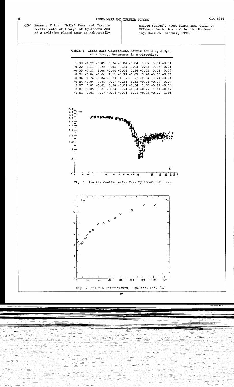
The extensive and well documented experiments by Sarpkaya, Refs. /1/ and /2/ are thebest known for cylinders exposed to oscillatoryflow. The resulting variation of the inertiacoefficients as function of KC-number (Ref./2/) are reproduced in Fig. 1. The decrease ininertia coefficient with increasing KC-numberis evident, with a pronounced local minimum forKC-numbers close to 10. For typical design waveconditions and for tubulars of jacket typestructures KC-values in the range from 30 andupwards are likely and C
M-values close to 1.4
are found to apply. Hereby an apparent addedmass coefficient of 0.4 appears, i.e. a reduction of 60 per cent compared to the theoreticalvalue of 1. It should be noted that it is notunusual to see these lower values of C and Cbeing used within the offshore induJ'b.y fo~load and response analyses.
superimposed on the wave flow. It is then evident that the direct use of the relation in Eq.(7) will lead to different values of the addedmass for different flow conditions, when theexperimentally determined cM-values are introduced. For the free cylinder the dynamic masswill then be smaller for large KC-numbers leading to apparently higher natural frequencies.
A critical review of some of the experimentally derived values is given next, including adiscussion of typical time traces of hydrodynamic loads for three cases.
On-bottom Pipeline
Tests and results are discussed for a freecylinder, a pipeline, and a group of risers.
In general, the focus has been on the derived values of the inertia coefficient and itsvariation with certain parameters, e.g. Keulegan-Carpenter number, wave to current ratio,pipe roughness, etc., and less interest hasbeen devoted to the reasons for these variations, and to the question when to apply thesevalues.
For pipelines on the seabed Sarpkaya andRajabi, Ref. /3/, Verley et al., Ref. /4/ andBryndum et al., Ref. /5/ have presented datafrom different test programmes. The agreementbetween the resulting force coefficients isgood, cf. Ref. /5/. Fig. 2 shows the resultsfrom Ref. /5/. Here the C -value for large KC-numbers is close to or ev~n exceeding 5, thusindicating a C -value of 4 or even higher, i.e.an increase o~almost 100 per cent compared tothe theoretical value of 2.29 (C
M- 3.29).
420
11 2Ca'4PD a .••••••••••••••••••••••••••• (3)
11 2 11 2'4PD a + Ca 4PD (a - x) ••••••••••••• (5)'r
Fa
For convenience Eq. (5) is quite often rewritten as:
FT ~ CM ~PD2a - Ca ~PD2 it •••••••••••••••• (6)
and the second term is treated like a physicalmass being added to the structural mass in dynamic analyses.
A major concern arises here, because extensive and well documented experiments and fieldtests have resulted in inertia coefficientsthat vary with the flow conditions, e.g. withthe Keulegan-Carpenter number. For single cylinders the C -values are found to decrease fromthe value 0~2 when the Keulegan-Carpenter number increases and also when a steady current is
since the Froude-Krylov term is unchanged andthe added mass force depends on the relativeacceleration.
From Eq. (4) the following relation appears:
11 24PD a •••.•••••••••••••••••••••••••• (2)
Due to its simplicity this relation is wellknown and often applied within the engineeringcommunity. Also for the assessment of the natural frequencies of dynamic susceptible cylindrical structures. The added mass can for certain structures constitute a significant partof the total mass, and accurate assessment ofthis part then becomes important.
When the virtual water body is replaced bya rigid walled cylinder in the acceleratingwater an additional force is created due to thelocal influence of the cylinder on the flow:this is the so-called added mass term, which isalso created by a cylinder accelerating in astill fluid. This force is expressed as:
The inertia load on a fixed cylinder isthus made up of two contributions, one from theoverall pressure variation in the fluid, theFroude-Krylov term, and one arising from thelocal effects the cylinder (rigid body) imposeson the accelerating fluid:
FT ~ ~D2a + Ca~PD2a ~ C
M~PD2a •••.•••• (4)
If the cylinder is itself moving (accelerating) in the accelerating water, the totalforce becomes:
This force is often referred to as theFroude-Krylov force.
this force ~quals the mass of the water bodytimes the acceleration, a, for a constantgradient. For a circular cylindrical body wethus have:
2
arc 6314 V. JACOBSEN, E.A. HANSEN 3
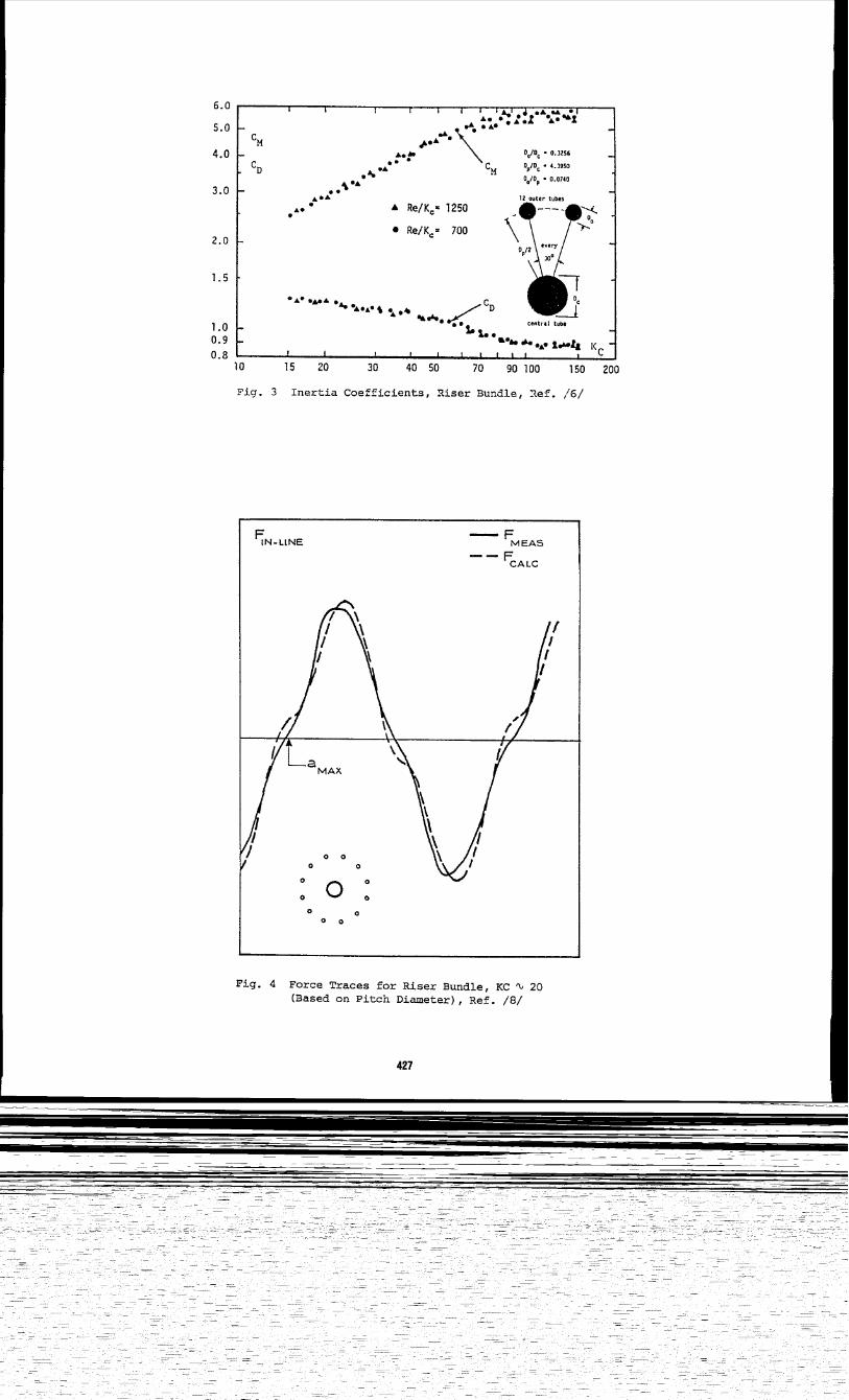
Ref. /6/, and Ottesen Hansen et al., Ref. /7/.For a configuration of pipes as shown in Fig. 3the inertia coefficient attains values between4 and 6 for KC-numbers exceeding 50. As thesevalues are based on the volume displaced by thepipes, a substantial increase in the added massis implied, an increase that will be associatedwith a significant decrease in the natural frequencies, thus making the riser bundle morevulnerable to dynamic excitation.
Discussion of cM-values from Exper~ments
Why do these variations in the values ofthe inertia coefficients appear? Why are theynot a complete and true reflection of the acceleration dependent inertia force, and whyshould they not be used in connection with Eq.(7) to provide estimates of the added mass fordynamic calculations? These questions will beaddressed next.
From an extensive joint industry project,Ref. /8/ , the recorded force on a multipiperiser having a geometry similar to the one ofFig. 3, is reproduced in Fig. 4. Also the forcecalculated based on the C and C -values derived from the traditionaf analysrs is shown.It is evident that the calculated force exceedsthe measured one when the acceleration is closeto its maximum. The use of a C -value of 3.5,as found from the analysis, do~s not give anaccurate estimate of the recorded load in theinertia dominated part of the force trace,where a cM-value close to 2 would give a betterfit.
The data reduction analysis used for theriser bundle is identical to the analysis mostcommonly applied for cylinders: achievement ofthe best overall fit of the Morison force expression to the measured force trace by adjustment of the two force coefficients, C and C •This approach is based on undistur~ed fr~estream kinematics. The attempt of correlatingthese to the forces created by the highly complex local flow field at the l3-pipe riserleads to the rather inappropriate C -values.Inappropriate in the sense that the~ neitherprovide adequate estimates of the inertia forcenor of the added mass coefficients when foundfrom Eq. (7).
The extensive research into pipeline stability carried out in the eighties demonstratedthat the traditional Morison based force calculation methods were inadequate in providingaccurate predictions of the temporal forcevariations. Descriptions of the pipeline-waterinteraction are provided by Jacobsen et al.,Ref. /9/, Verley et al., Ref. /4/, and Lambrakos et al., Ref. /10/. For details the reader
421
is referred to these papers, only a brief summary will be given here for illustrat:i;'I7.e purposes.
In one half wave period the flow aro1 'nd thepipeline creates a wake. Due to the .',c.versepressure gradient in the fluid this wake isbeing swept over the pipe prior to reversal ofthe free stream flow field in the subsequenthalf wave. The wake reversal is associated withlarge velocities in the vicinity of the pipeline, and these large velocities lead to largepressures, which integrate into large forces.This wake reversal effect has been most evidently observed in the lift force variation:Large peak forces appearing ahead of the maximum free stream velocity; but it also affectsthe horizontal or in-line force: A local peakappears in the recorded force time series, cf.Fig. Sa. This increase in hydrodynamic force isthus related to a near pipe velocity, and itshould consequently be treated like a dragterm. Traditional analyses cannot do this, asit is based on the Morison formula using theundisturbed free stream kinematics: At thetime of wake reversal and associated loadpeaks, the free stream velocity is very small,whereas the acceleration is close to its maximum. A true drag force contribution is therefore through the analysis procedure being related to the acceleration, and as a result ofthis it appears as an increased inertia coefficient. In reality there is nothing in thephysics that dictates a change in the inertiacoefficient from the theoretical value. Fromthe force time series in Fig. Sa it is in factseen that the large value of CM (4.3) overestimates the measured force right at the maximumacceleration.
An alternative analysis of the recordedforces has been made using the velocity recorded just above the pipeline instead of thefree stream velocity, cf. Ref. /9/. The velocity at the top of the pipe gives a reasonablereflection of the near pipe velocity field including the wake reversal, as demonstrated bythe detailed velocity measurements reported inRef. /4/. The result of the alternative analysis was a significantly increased accuracy inforce prediction, see Fig. 5b. The force coefficients also changed in values with inertiacoefficients being less than 3.29 in contrastto the results of the traditional analysis. Itis noteworthy that the use of cM-values smallerthan 3.29 yields calculated forces that aresmaller than those recorded at maximum acceleration. In combination with the opposite finding from using large cM-values it would indicate that the theoretical value of 3.29 wouldbe the better choice, and this has in fact provided very good estimates of the recorded forcetraces.
Free Cylinder
For the free cylinder case, the flow fieldnear the cylinder is more complex due to theinteraction of the shear layers and vortices
4 ADDED MASS AND INERTIA FORCES OTC 6314-. —.
generated from the two opposite sides. The vor- As proposed by Lundgren et al. it will bekites may be fully or partly shed during onehalf wave period and reversed during the next.
more feasible and correct to analyse hydrodyna-
For relatively low KC-numbers very strong vor-mic forces based on a theoretical value of theinertia (added mass) coefficient, and then fo-
tices are generated and only partly shed. Atthe phase angles with zero free stream velo-
cus on an improved description of the flow inproximity of the cylindrical structures. Lam-
cities and maximum accelerations these strong brakes et al., Ref. /12/, very recently advo-attached vortices will affect the local press- cated for the improved near field flow approachure field due to their large (rotational) velo-cities. These effects are integrated into the
with specific reference to shielding/bLockageeffects in large conductor arrays.
total load and related to the acceleration,hence they appear as inertia coefficient valuesdifferent from the theoretical one of 2. The THEORETICAL DEVELOPMENTSextremely small C -values reported in the lit-
%erature is associa ed with a complicated trans- T’heexamples discussed in the previous sec-verse vortex street and thus reflect the re- tion all pointed towards the general use ofsuits of a highly complicated velocity field at theoretically determined values of CM and Ca.the cylinder rather than actual changes in in-ertia/added mass force. The dramatic drop in For more than a century, analytical meansC -values disappears if the transverse vortexv
for obtaining the added mass for an accelerat-s reet is not formed. ing cylinder have been available: Extensive
treatments of the problem and its solution canGeneration of vortices, formation of wakes be found in numerous textbooks on hydrodyna-
and their reversal, and the inability of stand- mics, e.g. Lamb, Ref. /13/. Efficient numericalard procedures to properly account the associ- methods have also been presented, e.g. by vonated local flow field lead to small inertia Miiller,Ref. /14/ and Asp Hansenr Ref. /15/.coefficients at larger KC-numbers.
The traditional numerical methods are basedFig. 6 shows the measured and calculated on the inviscid flow theory, i.e. separation
force on a free cylinder (based on Ref. /1/). does not occur. By combining the flow fieldIt is seen that the low value of 1.3 for CM equations for a vorticity flow (Navier-Stokes)actually leads to a significant underprediction and for the flow associated with an impulsivelyof the measured force at the phase angles close acceleration of a cylinder, Asp Hansen, Ref.to maximum acceleration. Using a CM-value of /15/, very recently showed that the added mass2.0 would give a better and quite accurate es- of a cylinder accelerating under separated flowtimate of the recorded force here. Of course conditions is also determined by the potentialthe fit to the measured force would then be flow theory. This finding supports the conclu-less accurate at later phase angles, but this sion arrived at above based on experiments,change would hardly be noticeable, and the max- and, more importantly, this finding providesimum force would only be insignificantly af-fected.
the basis for obtaining accurate estimates ofthe added mass for any cylinder configurationfor use in the assessment of natural frequen-
From the three examples it would thus ap- cies.pear that the variations in inertia coeffici-ents as reported in the literature are in rea- In Ref. /15/ Asp Hansen also presented ality reflections of the inability of state-of numerical method for calculating the added mass-practice engineering methods (i.e. the Morison and inertia force coefficients for cylinders:equation and undisturbed free stream kinema- single - near a seabed -tics) in describing accurately and correctly
or in bundleslarrays.In this model the Laplace equation is solved
the hydrodynamic forces arising as a conse- based on the summation of a uniform flow field,quence of the extremely complex pressures in- dipoles and pairs of dipoles. These key ele-duced by the combination of global and local ments are introduced because: 1) The flowflow fields as affected by vortices and wakes. around an accelerating cylinder can be de-The resulting values of CM (and CD) may well be scribed by placing a dipole in the centre ofused to obtain reasonable estimates of hydrody- the cylinder, 2) The accelerating water flownamic loads but they do not have any merits around a fixed cylinder can be described bywith respect to estimating added mass and asso- superimposing the dipole and uniform flowciated dynamics. For such purposes the theore- field, and 3) Corrections due to disturbancestical values of Ca should be applied. of dipoles placed outside a cylinder can be
counteracted by placing a dipole inside theTo substantiate this conclusion reference cylinder, thus iteratively fulfilling the
is given to Lundgren et al., Ref. /11/, who stream line requirement on the cylinder sur-reported the results of the following tests face.with a circular cylinder: constant, unidirec-tional acceleration, small amplitude oscilla- T.he analytical/numerical developments havetions, and small amplitude oscillations super- been used to determine added mass coefficientsimposed on a large scale sinusoidal motion. In for a number of configurations.the latter case the small amplitude oscilla-tions were imposed at various phase angles of Four illustrative examples are discussed inthe main sinusoidal flow. All of these experi- the following:ment.sresulted in identical values of the addedmass coefficient, i.e. Ca = 1.
—.
a pipeline near a seabed (CM # 1 + Ca!) induced on cylinder No. 2. Note that this forceis in the opposite direction of the force on
added mass of two independent, closely cylinder No. 1 (hence the negative value in thespaced cylinders matrix) .
added mass and natural frequencies of cyl- When both cylinders are accelerated syn-inders in a 3 by 3 array chronously in the x-direction the total force
on each corresponds to an added mass coeffi-added mass for a riser bundle with 12 pe- cient of 1.03 + 0.23 = 1.26. And for motion inripheral pipes the y-direction the value becomes 1.03 - 0.23 =
0.8.Example 1 - Pipeline at a Seabed--------------------------------
The natural frequencies for synchronousFig. 7 shows the pipeline and the asymme- vibrations in the two directions are thus quite
tric seabed (e.g. caused by scouring process). different because the added mass values areThe potential flow theory model yields the fol- different, the value in the x-direction beinglowing results: more than 50 per cent larger than the value in
the y-direction.Accelerating water (x-direction):
c = 2.56 CMx My
= -0.03 Finally, it is noted that the inertia forcecoefficient for fluid acceleration in the x-di-
Accelerating cylinder (x-direction): rection equals 2.26 and in the y-direction 1.8c = 1.06 C = 0.001 for each cylinder.ax ay
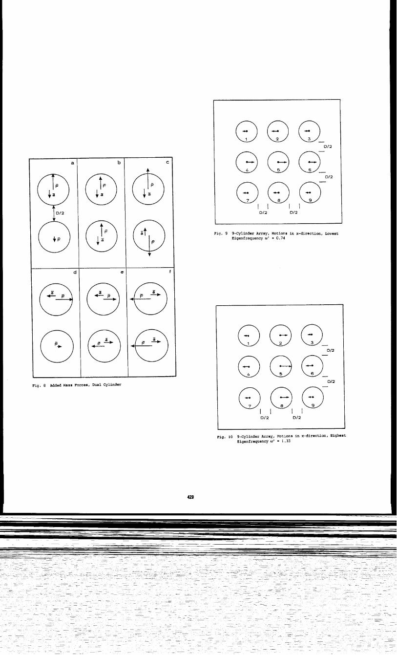
Accelerating cylinder (y-direction): Fig. 8 shows relative force magnitudes forc = 0.52 C = 1.05ax
various combinations of cylinder accelerations.ay
The directions of accelerations and associ-ated forces are shown in Fig. 7.
Example 3 -A3by3Arra~This thus illustrates that the relation
---- --------------------
cJI
=C + 1 is not generally correct since= ~.06 # C - 1 = 1.56. It also illus-
As demonstrated by Example No. 2 the vibra-
9
tion of one cylinder creates a pressure fieldt%tes that acce eration in one direction may that induces forces on neighboring cylinders.produce a force perpendicular to this direc- In order to determine the individual added masstion: The inertia or added mass coefficient is coefficients and natural frequencies of a sys-a vector (or matrix) rather than a scalar, and tern consisting of several cylinders, like theit is influenced by geometric boundary condi- array shown in Figs. 9 and 10, the eigenvalues
tions. of a matrix system need to be determined. Forthe present system the theory described in Ref.
Exam~le 2 - Two Closely Spaced Cylinders /15/ has been used to determine the added mass---- ----------------- --.---— --------
coefficients for movements restricted to theFor the configuration shown in Fig. 8 with x-direction. The result is given in the 9 by 9
two cylinders having a gap of half a diameter, matrix in Table 1.the added mass coefficient is a 4 by 4 matrixwith the following values: As for the dual cylinder case the values in
this matrix indicate the following: C . . is1.03 0.23 0.00 0.00 the equivalent added mass coefficient (~o%~ in0.23 1.03 0.00 0.00 x-direction) for cylinder j when cylinder i0.00 0.00 1.03 -0.23 accelerates in the x-direction. C is thus0.00 0.00 -0.23 1.03 the added mass coefficient for cyl%&;r 1 when
it accelerates alone (= 1.08) and Cal is theThis is to be interpreted as follows: If f“force equivalent for cylinder 4 when C$ lnder 1
cylinder 1 accelerates in the x-direction the accelerates (= 0.024). As can be seen the ef-added mass coefficient for cylinder 1 is C feet decreases for the cylinders further away
= 1.03 and the pressure field set up in atfiz from the one being accelerated.
fluid exerts a force on cylinder No. 2, corre-sponding to a C -value of 0.23, =i.e. * magni- Assuming identical structural stiffnesses
tude of this porce is 0.23 ● ~pD ● al . for the nine cylinders and assuming that their
This force acts in the same direction as f~e structural mass is zero, the relative naturalforce on cylinder No. 1, i.e. in the opposite frequencies for the nine eigenmodes have been
direction of the acceleration of cylinder No. determined from the equation of motion to be:
1. In other words, an acceleration of cylinder1 in the positive x-direction creates a total (0.74, 0.79, 0.86, 0.97, 0.98, 0.99, 1.12,
for~e on the dual pipe system equal to 1.26 ● ~ 1.22, 1.33)
PD ● a in the negative x-direction.as compared to the value of 1 for a single free
When cylinder 1 is accelerated in the y-di- cylinder. The natural frequencies thus vary
rection a force corresponding to a C -value of with i’30 per cent around the single cylinder
1.03 is exerted on this cylinder, awhereas aforce corresponding to a Ca-value of 0.23 is
---
6 ADDED MASS ANO INERTIA FORCES oTC 6314
value depending on the eigenmode being excited. example of a single cylinder: if the hydrody-(For realistic values of the Sf21VXlXW?tl mass, namic load from water inside the cylinder isthe range of natural frequencies decreases to included, the same result is obtained here.typically * 10 per cent around the value forthe single cylinder, a variation that may still Note, however, that the concept of addedbe significant for dynamic response evalua- mass may be misleading if it is considered ations). physical mass of water instead of the inte-
Figs. 9 and 10 show the eigenmodes corre-gratea effect of a pressure field set up by theaccelerating bodly: If a cylinder, say of dia-
sponclingto the lowest and highest natural fre- meter 0.5 D is placed in the centre of thequency, respectively. The vectors indicate the ring formeapby the 12 outer cylinders, thedirection anclrelative motion amplitude of each force on these remains equal to 2.45 “ 12 “ pAacylinder. The lowest eigenmode has the central when the system is accelerated, although therow moving in opposite direction of the upper volume of entrapped water has been reduced fromand lower rows. For the highest eigenmode the 0.67 A to 0.42 A . The force on the outer ringcentral. vertical row of cylinders moves away of 12 ‘cylinders ~s caused by the pressures infrom the front row and against the rear row. the water inside [and outside) the ring antiisIf all 9 cylinders are bound to vibrate syn- not related to a physical water mass.chronously the adcledmass coefficient is foundfrom the numerical calculations to equal 1.008,or for all practical purposes 1. IWACT ON NATURAL FREQUENCIES OF OFFSHORE
Certain structural elements like risers andThis example is included to illustrate the conductors and also some deepwater platforms
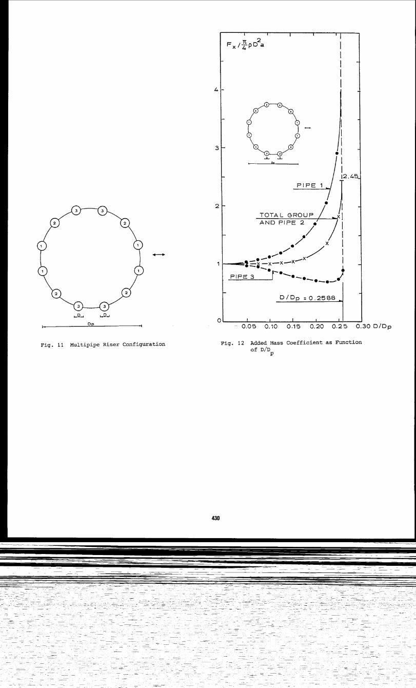
effect of increasing the closeness of several are prone to respond dynamically to time vary-cylinders on the total added mass force. The ing loads, e.g. from waves and vortex shedding.12-pipe configuration shown in Fig. 11 is con- When interference effects are small or negli-sidered for different diameters of the cyl- gible, i.e. when spacings between cylinders areinders. large, the added mass coefficient value should
be taken equal to 1 for all cylinders. DesignFor small values of the cylinder, diameter
D,procedures using CM-values of the order of 1.4
compared to the pitch diameter, D , the to procluceC -values of 0.4 will lead to esti-added mass is 1.0 for all peripheral pi~es, as mated highe~ natural frequencies, with in-they act as individual cylinders. Nhen increas- creases in the order of 5-10 per cent dependinging D the interference effect increases and on how large a fraction the addecimass is ofdifferent C -values appear for the cylintiers the total dynamic mass. For structures where(only 3 dif~exent values for symmetry reasons). buoyancy tanks form a substantial part of theThis is shown in Fig. 12, where also the value structure, this difference in frequency esti.-for the total bundle is given. The C -value for mates may increase significantly because thecylinder No. 2 is equal to the Ca-va~ue for the aclcledmass is large compared to the structuraltotal bundle. mass for such elements. The dynamic mass of a
neutrally buoyant tank will be 40 per centAs D/D approaches 0.26, where contact be- larger when C = 1 is usea insteaclof C = 0.4.
tween all fwelve cylinders is established, the For closely aspaced structural eleme%s thetotal C -value approaches 2.45, corresponding added mass (and thereby the natural frequen-to a fo$ce of 2.45 - 12 ● pAa or 1.97 PA a,
Yties) depends on the actual geometry and on the
where A is the cross-sectional area of one c 1- vibration moties,e.g. whether elements act in-inder, anc7A is the cross-sectional area for a dividually or in unison. The numerical model,cylinder wit% diameter D . Ref. /15/, can for these cases be applied to
P obtain the values of the Ca-matrix.The entrapped mass of water is 0.67 PA . Of
the added mass force 0.67 PA a can be sa~d tobe used to accelerate the ‘entrapped water, SUNNARY AND CONCLUSIONleaving 1.3 PA a. Based on the total cross-sec-tional area (~1.47 A ) the added mass coeffi- Data for a variety of structures have beencient then equals 0.8Lf’,i.e. close to 1. reviewed. Supported by basic hydrodynamic con-
sitierations ancl the results of analytical/nu-For a similar case with a large number of merical developments it has been concluded that
very small diameter cylinders forming a closed acldedmass coefficients can be accurately ae-circle, the aaded mass coefficient basea on the termined basea on potential flow theory. Cpitch diameter becomes equal to 2. Of this -values so determined are generally applicabl$value half is due to the pressure outside the also in separated flows. For single cylinders“large cylinder” (the sane as for a single cyl- C thus equals 1 (Cinder with diameter D ). The second half is due aaflat seabed Ca= P.;92;c;:3Y9):ipe1 ines ‘nto the pressure in de water entrappea insidethe ring formed by the small cylinders. Note For multipipe configurations calculationthat for this system the inertia coefficient examples have been given based on a numericalalso equals 2. model of general valitiity for 2-dimensional
flows.This apparently surprising result that C =
CM, is not in contradiction with the classigal
.—
“.- .J. .-X V . iJ.+iLUDD13N, b .A. HANW3!X 7
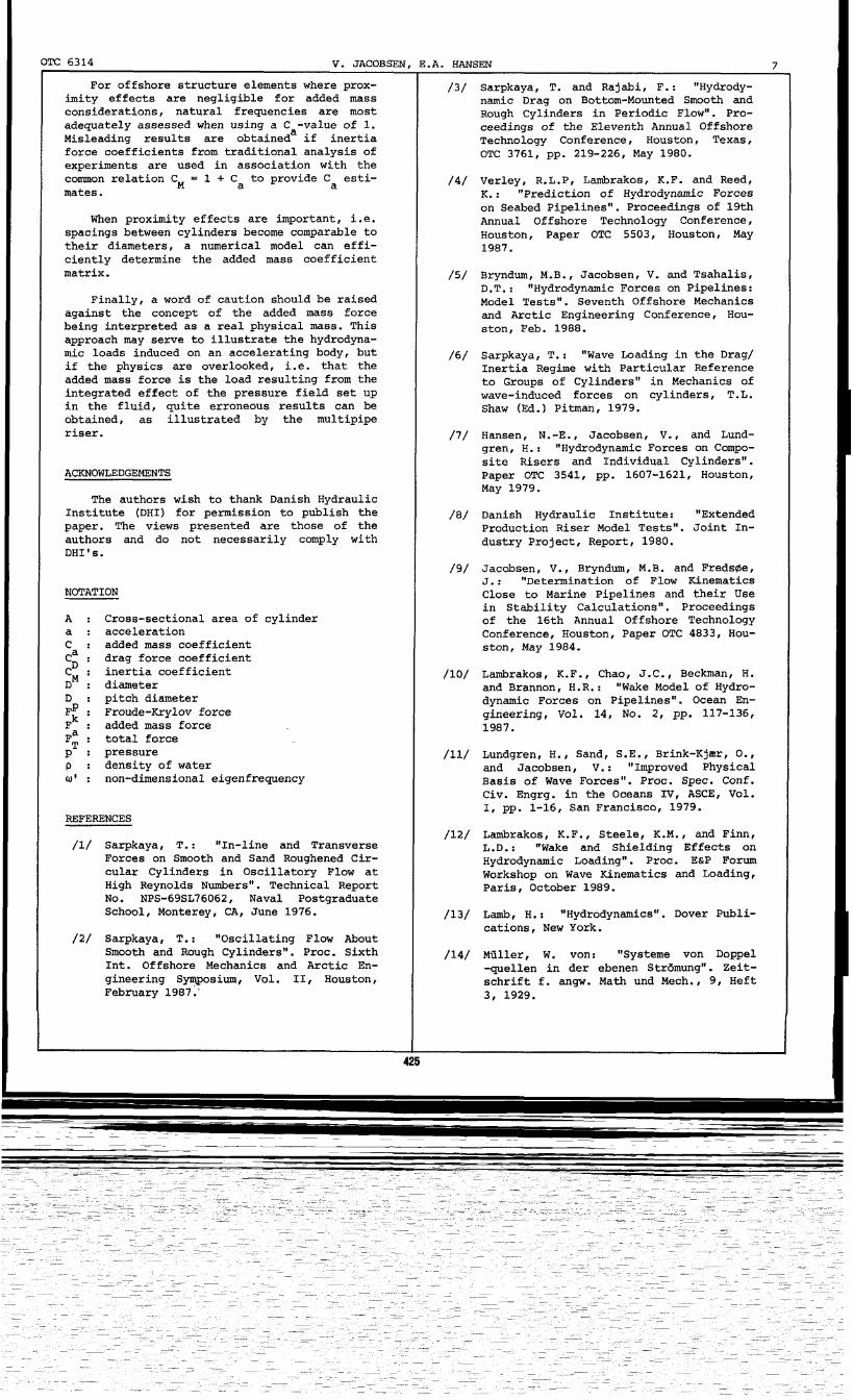
For offshore structure elements where prox- /3/ Sarpkaya, T. and Rajabi, F.: “Hydrody-imity effects are negligible for added mass namic Drag on Bottom-Mounted Smooth andconsiderations, natural frequencies are most Rough Cylinders in Periodic Flow”. Pro-adequately assessed when using a C -value of 1.Misleading results are obtaineda if inertia
ceedings of the Eleventh Annual OffshoreTechnology Conference, Houston, Texas,
force coefficients from traditional analysis of OTC 3761, pp. 219-226, May 1980.experiments are used in association with thecommon relation C = 1 + Ca to provide C esti-
M a /4/ Verley, R.L.P, Lambrakos, K.F. and Reed,mates. K .: “Prediction of Hydrodynamic Forces
When proximity effects are important, i.e.on Seabed Pipelines”. Proceedings of 19thAnnual Offshore Technology Conference,
spacings between cylinders become comparable to Houston, Paper OTC 5503, Houston, Maytheir diameters, a numerical model can effi- 1987.ciently determine the added mass coefficientmatrix. /5/ Bryndum, M.B., Jacobsen, V. and Tsahalis,
D.T. : ftHydrodynaic Forces on Pipelines:Finally, a word of caution should be raised Model Tests”. Seventh Offshore Mechanics
against the concept of the added mass force and Arctic Engineering Conference, Hou-being interpreted as a real physical mass. ‘This ston, Feb. 1988.approach may serve to illustrate the hydrodyna-mic loads induced on an accelerating body, but /6/ Sarpkaya, 1’.: “Wave Loading in the Drag/if the physics are overlooked, i.e. that the Inertia Regime with Particular Referenceadded mass force is the load resulting from the to Groups of Cylinders” in Mechanics ofintegrated effect of the pressure field set up wave-induced forces on cylinders, T.L.in the fluid, quite erroneous results can beobtained, as illustrated by the multipipe
Shaw (Ed.) Pitman, 1979.
riser. /7/ Hansen, N.-E., Jacobsen, V., and Lund-grent H.: “Hydrodynamic Forces on Compo-site Risers and Individual Cylinders”.
ACKNOWLEDGEMENTS Paper OTC 3541, pp. 1607-1621, Houston,May 1979.
The authors wish to thank Danish HydraulicInstitute (DHI) for permission to publish the /8/ Danish Hydraulic Institute:paper.
“ExtendedThe views presented are those of the Production Riser Model Tests”. Joint In-
authors and do not necessarily comply with dustry Project, Report, 1980.DHI’s.
/9/ Jacobsen, V., 13ryndum,M.B. and Fredstie,J.: “Determination of ‘Flow Kinematics
NOTATION Close to Marine Pipelines and their Usein Stability Calculations”. Proceedings
A : Cross-sectional area of cylindera: acceleration
of the 16th Annual Offshore Technology
c:Conference, Houston, Paper OTC 4833, Hou-
added mass coefficientCa : drag force coefficient
ston, May 1984.
CD ;~M
inertia coefficient /10/ bmbrakos, K.F., Chao, J.C., Beckman, H.: diameter and Brannon, H.R. x *,W&e Model of Hydro-
D : pitch diameter@ : Froude-Krylov force
dynanic Forces on Pipelines”. OCean En-
~k : gineering, Vol. 14, No. 2, pp. 1~7-136,added mass force 1987.
F; : total force
P : pressure /11/ Lundgren, H., Sand, S.E., Brink-Kjax, O.,P : density of water and Jacobsen, V.: “Improved PhysicalU* : non-dimensional eigenfrequency Basis of Wave Forces”. Proc. Spec. Conf.
Civ. Engrg. in the Oceans IV, ASCE, Vol.1, pp. 1-16, San Francisco, 1979.
REFERENCES
/12/ Lambrakos, K.F., Steele, K.M., and Finn,/1/ Sarpkaya, T.: “In-line and Transverse L.D.: “Wake and Shielding Effects on
Forces on Smooth and Sand Roughened Cir- Hydrodynamic Loading”. Proc. EsP Forumcular Cylinders in Oscillatory Plow at Workshop on Wave Kinematics and Loading,High Reynolds Numbers”. Technical ReportNo.
Paris, October 1989.NPS-69SL76062 , Naval Postgraduate
School, Monterey, CA, June 1976. /13/ Lamb, H.: “Hydrodynamics”. Dover publi-
/2/ Sarpkaya, T.:cations, New York.
“Oscillating Flow AboutSmooth and Rough Cylinders”. Proc. Sixth /14/ Miiller, W. von: “Systeme von DoppelInt. Offshore Mechanics and Arctic En-gineering S~posium, Vol. II, Houston,
-quellen in der ebenen Str6mung”. Zeit-
February 1987.’schrift f. angw. Math und Mech., 9, Heft3, 1929.
---
-—--- ---- -.. . ..-...43 . “-.
/15/ Hansen, E.A. : “Added Mass and Inertia Shaped Seabed”. Proc. Ninth Int. Conf. onCoefficients of Gzoups of Cylinders And Offshore Mechanics and Arctic Engineer-of a Cylinder Placed Near an Arbitrarily ing, Houston, February 1990.
Table 1 Added Mass Coefficient Matrix for 3 by 3 Cyl-inder Array. Movements in x-Direction.