OTC OTC-OTC-24386-MS DORIS - Monitoring Robot for Offshore Facilities Guilherme P.S. de Carvalho, Gustavo M. Freitas, Ramon R. Costa, Gustavo H.F. de Carvalho, Jose F.L. de Oliveira, Sergio L. Netto, Eduardo A.B. da Silva, Marco F.S. Xaud, Liu Hsu, Gabriel Motta-Ribeiro, Alex F. Neves, Fernando C. Lizarralde, Ighor Marcovistz, Alessandro J. Peixoto and Eduardo V.L. Nunes, UFRJ; Pål J. From, UMB; Mauricio Galassi, Petrobras; and Anders Røyrøy, Statoil Copyright 2013, Offshore Technology Conference This paper was prepared for presentation at the Offshore Technology Conference Brasil held in Rio de Janeiro, Brazil, 29–31 October 2013. This paper was selected for presentation by an OTC program committee following review of information contained in an abstract submitted by the author(s). Contents of the paper have not been reviewed by the Offshore Technology Conference and are subject to correction by the author(s). The material does not necessarily reflect any position of the Offshore Technology Conference, its officers, or members. Electronic reproduction, distribution, or storage of any part of this paper without the written consent of the Offshore Technology Conference is prohibited. Permission to reproduce in print is restricted to an abstract of not more than 300 words; illustrations may not be copied. The abstract must contain conspicuous acknowledgment of OTC copyright. Abstract Safety and efficient operation are imperative factors to offshore production sites and a main concern to all Oil & Gas companies. A promising solution to improve both safety and efficiency is to increase the level of automation on the platforms by introducing intelligent robotic systems. Robots can execute a wide variety of tasks in offshore environments, including monitoring and inspection, diagnosis and maintenance, process production intervention, and cargo transport operations. In particular, considering the distance of offshore platforms from the Brazilian coast, such technology has great potential to increase safety by decreasing the number of onboard personnel, simplify logistics, and reduce operating costs of Brazilian facilities. The use of robots can also allow proactive integrity management and increase frequency and efficiency of platform inspection. DORIS is a research project which endeavors to design and implement a mobile robot for remote supervision, diagnosis, and data acquisition on offshore facilities. The proposed system is composed of a rail-guided mobile robot capable of carrying different sensors through the inspected environment. The robot can also analyze sensor data and identify anomalies, such as intruders, abandoned objects, smoke, fire, and liquid leakage. The system is able to read valves and make machinery diagnosis as well. To prove the viability of the proposed system, an initial prototype is developed using a Roomba robot with several onboard sensors and preliminary tests have been performed in a real environment similar to an offshore platform. The tests show that the robot is capable of indicating the presence or absence of objects in a video stream and mapping the local area with laser sensor data during motion. A second prototype has been built to test the DORIS mechanical design. This prototype is used to test concepts related to motion on a rail with straight, curved, horizontal, and vertical sections. Initial results support the proposed mechanical concept and its functionalities. Introduction During the last decade, several Oil & Gas companies, research groups, and academic communities have shown an increased interest in the use of robotic systems for operation of offshore facilities. Recent studies project a substantial decrease in the level of human operation and an increase in automation used on future offshore oil fields (Skourup and Pretlove, 2009). Today, robotic systems are used mainly for subsea tasks, such as mapping the seabed and performing inspection tasks on underwater equipment, risers, or pipelines using Remotely Operated Vehicles (ROVs) or Autonomous Underwater Vehicles (AUVs). Topside operations, on the other hand, have not yet adopted robotized automation as a solution to inspection and operation tasks. From (2010) points out the potential increase in efficiency and productivity with robot operators rather than humans, given that robots work 24 hours per day and 7 days per week, are less prone to errors, and are more reliable. Another highlighted point is the improvement Health, Safety, and Environment (HSE) conditions, as robots can replace humans in tasks performed in unhealthy, hazardous, or confined areas. In the specific Brazilian case, the Oil & Gas industry is growing at a high pace, mainly due to the recent discoveries of big oil fields in the pre-salt layer off the Brazilian coast. These oil reservoirs are located farther than 300 km from the shore and at depths of 5000 to 7000 km. These factors, especially the large distances, motivate the development of an offshore production system with a high degree of automation based on advanced robotics systems.
Transcript
OTC OTC-OTC-24386-MS
DORIS - Monitoring Robot for Offshore Facilities Guilherme P.S. de Carvalho, Gustavo M. Freitas, Ramon R. Costa, Gustavo H.F. de Carvalho, Jose F.L. de Oliveira, Sergio L. Netto, Eduardo A.B. da Silva, Marco F.S. Xaud, Liu Hsu, Gabriel Motta-Ribeiro, Alex F. Neves, Fernando C. Lizarralde, Ighor Marcovistz, Alessandro J. Peixoto and Eduardo V.L. Nunes, UFRJ; Pål J. From, UMB; Mauricio Galassi, Petrobras; and Anders Røyrøy, Statoil
Copyright 2013, Offshore Technology Conference This paper was prepared for presentation at the Offshore Technology Conference Brasil held in Rio de Janeiro, Brazil, 29–31 October 2013. This paper was selected for presentation by an OTC program committee following review of information contained in an abstract submitted by the author(s). Contents of the paper have not been reviewed by the Offshore Technology Conference and are subject to correction by the author(s). The material does not necessarily reflect any position of the Offshore Technology Conference, its officers, or members. Electronic reproduction, distribution, or storage of any part of this paper without the written consent of the Offshore Technology Conference is prohibited. Permission to reproduce in print is restricted to an abstract of not more than 300 words; illustrations may not be copied. The abstract must contain conspicuous acknowledgment of OTC copyright.
Abstract Safety and efficient operation are imperative factors to offshore production sites and a main concern to all Oil & Gas companies. A promising solution to improve both safety and efficiency is to increase the level of automation on the platforms by introducing intelligent robotic systems. Robots can execute a wide variety of tasks in offshore environments, including monitoring and inspection, diagnosis and maintenance, process production intervention, and cargo transport operations.
In particular, considering the distance of offshore platforms from the Brazilian coast, such technology has great potential to increase safety by decreasing the number of onboard personnel, simplify logistics, and reduce operating costs of Brazilian facilities. The use of robots can also allow proactive integrity management and increase frequency and efficiency of platform inspection.
DORIS is a research project which endeavors to design and implement a mobile robot for remote supervision, diagnosis, and data acquisition on offshore facilities. The proposed system is composed of a rail-guided mobile robot capable of carrying different sensors through the inspected environment. The robot can also analyze sensor data and identify anomalies, such as intruders, abandoned objects, smoke, fire, and liquid leakage. The system is able to read valves and make machinery diagnosis as well.
To prove the viability of the proposed system, an initial prototype is developed using a Roomba robot with several onboard sensors and preliminary tests have been performed in a real environment similar to an offshore platform. The tests show that the robot is capable of indicating the presence or absence of objects in a video stream and mapping the local area with laser sensor data during motion. A second prototype has been built to test the DORIS mechanical design. This prototype is used to test concepts related to motion on a rail with straight, curved, horizontal, and vertical sections. Initial results support the proposed mechanical concept and its functionalities.
Introduction During the last decade, several Oil & Gas companies, research groups, and academic communities have shown an increased interest in the use of robotic systems for operation of offshore facilities. Recent studies project a substantial decrease in the level of human operation and an increase in automation used on future offshore oil fields (Skourup and Pretlove, 2009).
Today, robotic systems are used mainly for subsea tasks, such as mapping the seabed and performing inspection tasks on underwater equipment, risers, or pipelines using Remotely Operated Vehicles (ROVs) or Autonomous Underwater Vehicles (AUVs). Topside operations, on the other hand, have not yet adopted robotized automation as a solution to inspection and operation tasks.
From (2010) points out the potential increase in efficiency and productivity with robot operators rather than humans, given that robots work 24 hours per day and 7 days per week, are less prone to errors, and are more reliable. Another highlighted point is the improvement Health, Safety, and Environment (HSE) conditions, as robots can replace humans in tasks performed in unhealthy, hazardous, or confined areas.
In the specific Brazilian case, the Oil & Gas industry is growing at a high pace, mainly due to the recent discoveries of big oil fields in the pre-salt layer off the Brazilian coast. These oil reservoirs are located farther than 300 km from the shore and at depths of 5000 to 7000 km. These factors, especially the large distances, motivate the development of an offshore production system with a high degree of automation based on advanced robotics systems.
2 OTC OTC-24386-MS
Fraunhofer IPA (Bengel et al., 2009) was the first research group to demonstrate the applicability of mobile robots for offshore inspection and maintenance tasks. In their work, a mobile robot was capable of navigating safely, building maps, and executing inspection tasks autonomously throughout a topside offshore platform. This work has also motivated the development of recent studies on offshore robotics.
DORIS − General Overview and Main Challenges
Bengel and Pfeiffer (2007) and Kyrkjebø et al. (2009) study possible scenarios where robots can replace human operators in important tasks on a platform, which varies from specific operations to overall platform monitoring. According to these studies, both visual inspection tasks and physical intervention on process equipment, such as opening and closing a valve, can be achieved using robots equipped with multiple sensors.
In light of these predictions, the DORIS project aims at developing a mobile robot intended to perform monitoring, inspection, and intervention tasks on an offshore platform. To this end, the system must be able to move throughout the environment to be monitored carrying several sensors, analyze sensor data, and interpret the results. For these purposes, the system is composed of a rail guided robot with cameras, microphones, gas, vibration and temperature sensors, and a manipulator arm. The sensors can identify abnormalities such as intruders in restricted areas of the platform, abandoned objects, smoke and fire, and liquid and gas leakages. Furthermore, the robot is able to make machinery diagnosis, read process plant instruments, and perform interventions on valves and equipment using the onboard manipulator arm.
The robot can be operated in two different modes: autonomous mode or by teleoperation. The teleoperation and monitoring capabilities guarantee online access to the embedded sensors, providing information about the surrounding environment and robot operation conditions with intelligent real-time processing.
Furthermore, both the rail and the robot are designed to be modular. Additional modules can be attached to the robot if necessary, for example to include additional sensors, and the rail track can easily be modified by adding rail modules, enabling operation in different areas of the platform. Robot modules are organized by functionality, for example traction and sensing modules.
Considering the robot functionalities described above and the offshore environment, several challenges arise. Firstly, the robot must move through a 3D rail composed of horizontal, vertical, straight, and curved segments. Thus, the robot mechanical system must be intelligently designed to give flexibility and complacency for curved motion while keeping orientation, avoid sliding, and be able to move relatively fast, for example in case of emergency situations. Furthermore, the traction system must compensate the robot weight in vertical sections while providing smooth motion.
In addition, the robot must be designed to resist the aggressive environment it is subjected to operate in. Temperatures on offshore facilities can vary between -30°C to 50°C, relative humidity can reach 100%, and there may be splash water, salty air, storms, and high extensive corrosion (Graf, Pfeiffer and Staab, 2007). Also, the robot parts must have special enclosures to turn it explosion-proof and allow operation on classified areas.
Other challenges include providing good battery autonomy while maintaining high computational power and space optimization of the modules. Further complications arise as the system is designed to move in confined areas, and the requirement of efficient wireless communication with operators, providing online information with full access to sensors data. Finally, the robot has a modular design, employing “plug and play” extensions and flexibility.
In the following section, some offshore robotic systems currently being used or developed are presented and special attention is given to rail guided robots. Then, a detailed presentation of DORIS system is given, dividing it into five main systems: mechanics, electronics, power supply, software, and signal processing. Finally, the description of the prototypes, which prove important concepts for the improvement of the robot’s design, is given together with the preliminary results.
Offshore Robotics and Rail Guided Robots In this section, we present the main robotic systems currently operating or being developed for operation on Oil & Gas facilities, especially offshore platforms. These robots are developed to perform inspection and monitoring tasks on process plants aiming to improve efficiency and productivity, reduce logistics costs, and increase HSE conditions for human operators. In this setting, robots capable of moving on a rail with curves and/or vertical sections are studied, with special interest in the motion capabilities and mechanisms used for such challenging movements, such as vertical climbing and curve traversing. Offshore Robotics
There already exist several platforms with a high level of automation, especially in the North Sea, Australia and the Persian Gulf, where there are small completely unmanned platforms. However, this degree of automation is obtained without the use of fixed-base or mobile robots. The use of robots in the oil and gas industry is still in the testing phase. There are, however, some projects on this topic: These projects study the use of industrial manipulators on processing plants and mobile robots performing maintenance and inspection tasks on offshore platforms.
Anisi et al. (2010) show onsite demonstrations of a certified industrial manipulator, IRB5500, and investigate how a conventional robot behaves under severe environmental conditions. They show that robots can be used on oil and gas facilities to perform operations requiring both high precision and strength, regardless of weather conditions. SINTEF-ICT is another group interested in manipulators applied to the oil and gas industry. SINTEF has an indoor facility with three robots interacting with a process plant similar to those found on platforms. Concepts related to monitoring, inspection, and
OTC OTC-24386-MS 3
intervention using robotic manipulators for the operation of a platform are being studied but not yet implemented on a real operational facility. Kyrkjebø et al. (2009) show a solution using a 3D robot vision system and a control architecture for remote inspection and maintenance operations on processes similar to the ones found on a platform.
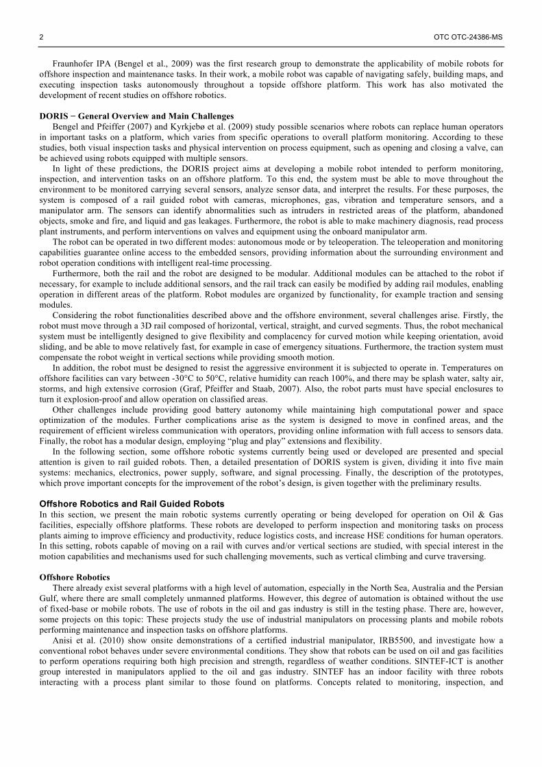
Bengel et al. (2009) present the Fraunhofer mobile robot called MIMROex. The wheeled robot can move through the platform autonomously and is designed to perform monitoring and inspection tasks, such as gauge reading and monitoring of gas concentrations. However, the robot still does not interact actively in the operation of the platform. Figure 1 shows MIMROex performing an inspection task during field test on a platform. MIMROex was the first autonomous service robot that has ever been operated in an offshore environment and it has illustrated the applicability of mobile robots on offshore platforms.
Figure 1 – Fraunhofer MIMROex robot inspecting a process plant during field test on the topside of a platform (Bengel et al., 2007).
Finally, the group NREC/CMU developed a mobile robot named Sensabot Inspection Robot, which is able to safely and
cost-effectively inspect and monitor hazardous and remote production facilities (CMU/NREC, 2012). It is equipped with driving cameras, microphones, and vibration, temperature and gas sensors, enabling visual, audio, vibration, temperature, and gas inspection. Furthermore, the robot is certified to operate in explosive and toxic environments, can sustain high temperatures, and is able to reach areas with difficult access. Currently, NREC/CMU is developing a 7 degrees of freedom (DoF) manipulator so that, besides just performing monitoring tasks, the robot will be able to make interventions in process plant. This may include tasks such as operation of valves, control switch and electrical panels operation, retrieving or delivering parts, sensor testing and calibration, fluid and gas sampling, and opening and closing doors or gates. Figure 2 shows Sensabot performing inspection on an offshore plant during field test and its new manipulator arm, currently being developed.
Rail Guided Robots
Climbing robots are extensively studied in the robotics literature and different adhesion concepts are used to move the robot on a vertical rail. The 3DCLIMBER robot (Tavaloki et al., 2008) and Climbot (Guan et al., 2009) use mechanical adhesion with grippers to climb tubular structures and scan the structure’s surface. Pneumatic, magnetic, and even electrostatic adhesion forces are also considered for climbing robots in MRWALLSPECT (Choi, Park and Kang, 2004), MINOAS Crawler (Fondahl et al., 2012) and Stickybot (Kim et al., 2007), respectively. However, these concepts are not appropriate for DORIS, given that they are designed for specific environments and contact surface conditions.
As DORIS must move in a 3D space performing curves, horizontal, and vertical movements, the most suitable concept is locomotion on a rail. The use of a pre-specified path of the rail reduces concerns such as localization and obstacle avoidance while allowing the robot to move relatively fast through its workspace. Motion is simple, as the robot has only one DoF: it can move forwards or backwards. On the downside, the use of rails limits the robot workspace as the path is fixed. On the other hand, the rail may be installed to pass all key areas and a modular design may allow for path modification. Rail guided robots can be further divided into two main groups: the ones which use rack and pinion systems and friction-based wheeled robots. A
4 OTC OTC-24386-MS
wheeled solution is more suitable for DORIS purposes, given that it allows for faster, simpler, and more efficient motion rather than using a rack and pinion.
Figure 2 – Sensabot Inspection Robot on an offshore environment and its 7 DoF manipulator arm being currently developed
(CMU/NREC, 2012). Versatrax Vertical Crawler uses three rubber tracks to move inside a pipe (Inuktun, 2013). POBOT (Fauroux and Morillon,
2010) and Pruning Climbing Robot (Kawasaki et al., 2008) are pole climbing robots that use a self-locking property with friction between the wheels and the rail, which makes it able to keep the position with no energy consumption. UT-PCR (Baghani, Ahmadabadi and Harati, 2005) is a light-weight robot that moves vertically on a rail with ordinary wheels being pressed against the rail using springs, which ensure normal forces to cancel the weight force effect on the robot. ARTIS, developed by DFKI Robotics Innovation Center, is a modular rail guided robot that moves on a rectangular cross sectioned rail and performs inspection and maintenance tasks in ballast water tanks (Christensen et al., 2011). The robot has a polyurethane traction wheel, driven by a motor, on the upper surface of the rail and guide wheels on the sides and the bottom faces of the rail. Modules are connected using couplings composed of two ball joints and a rod. Figure 3 shows ARTIS robot.
Figure 3 – ARTIS robot with 5 modules and manipulator arm, and the robot moving on a rail with rectangular cross section.
System Overview In this section, we present a detailed description of the DORIS project dividing it into five main systems: mechanics, electronics, power supply, software, and signal processing. The mechanics describes the developed mechanical design of both the rail and the robot. The electronics covers the considered architecture, equipment, and failure scenarios. The power supply describes the number and type of batteries for both the main and the backup systems, as well as energy distribution. Then, the
OTC OTC-24386-MS 5
software architecture, which uses Robot Operating System (ROS), is described in detail. Finally, in the signal processing section the considered sensors and algorithms are described. Mechanics
The main objectives of the mechanical design of the DORIS project are to appropriately design the rail, the traction module, the passive modules, and the joints used to couple two modules to achieve the desired overall performance of the robot. The design of the rail and the robot must allow the robot to move smoothly in a 3D space, perform curves, horizontal and vertical movements, and to make full stops anywhere on the rail. Also, considering the aggressive corrosion and weather conditions on the platforms, the choice of rail and robot materials are imperative to the success of the project. Finally, certified solutions applicable to an offshore environment must be considered.
The rail is designed to be as simple as possible, leaving the complexity to the robot. This is motivated by the fact that the rail may be extremely long so that the cost of it should be kept to a minimum. The rail consists of two modules that are made from simple hollowed tubular segments with 3 in diameter: a straight module and a curved module made by bending straight segments by 90 ̊. The support is attached on the top of the rail, giving pendulum-like characteristics, which gives good stability and reduces the moments and forces acting on the rail.
DORIS is composed of four modules at its default configuration but is designed so that additional modules can be added. The total weight of this configuration is estimated at 50 kg. The traction module is composed of two main parts mounted on a base: the central traction system and the two sets of gimbals. The two gimbals, one coupled to the other with orthogonal pivot axes, are mounted on the base, providing horizontal and vertical rotation while preventing rotation around the rail. The inner gimbal comprises four equally spaced guide wheels that closely encompass the rail. These gimbals are important for the robot’s guidance, stability, and support.
Traction is obtained by friction between two traction wheels and the rail. The two traction wheels are mounted on a prismatic mechanism that can slide horizontally and vertically on guide bars through linear bearings. To hold the robot on vertical positions, a clamping mechanism is designed to force the traction wheels against the rail, applying radial forces to cancel the robot’s weight force, regulating it with a motor. This motor drives spindles that opens or closes levers connected to the wheels. The self-locking property of this mechanism guarantees that the applied force remains the same in case of motor breakdown, avoiding the robot to fall on vertical sections. Finally, two types of joints are designed: the double Cardan joint and a spring-based joint with a steel cable. Figure 4 shows the robot design and a straight section of the tubular rail.
Figure 4 – The DORIS mechanical design, showing a straight section of the rail with a support, the traction module, the passive module and a double Cardan joint used to couple the two modules.
Electronics
6 OTC OTC-24386-MS
DORIS electronics project’s main objectives are to provide an embedded computational support for robot control, signal processing, task managing, and local and remote communication. Robot control is manually or automatically achieved through the robot’s drivers that can receive position, velocity, or current setpoints. For signal processing, the embedded computers run heavy algorithms, requiring high processing capacity, fast RAM, and large physical storage space. Task managing can be either in automatic mode (pre-scheduling by software) or in manual mode (real-time remote operation).
Local communication interfaces between the onboard DORIS computer and major peripheral devices are the following: Ø Cameras, microphones, data acquisition board: USB or Ethernet; Ø Drivers: CAN Bus; Ø Network switch: Ethernet;
Interfaces between robot modules are only Ethernet and CAN cables, which require Ethernet. The simplified electronics architecture distributed along the modules is shown in Fig. 5. For remote communication, Wi-Fi is used for main operations, and radio is used for emergency purposes.
Figure 5 - Electronics architecture distributed along the robot modules.
OTC OTC-24386-MS 7
In addition, since the robot operates in hazardous environments, it needs to be robust and safe, i.e., environmentally sealed against water, ingression of objects, and wide temperature range, mechanically protected from impact and vibration, electrically protected to avoid explosion by ignition, and equipped with a monitoring system. The electronics also need to comply with the modular structure of the robot, and allow its modules to be freely rearranged without any complications in the system functioning.
Furthermore, there are several circuits for protection and monitoring of the robot devices distributed in the electronics architecture. Fuses and diode-based circuits protect each device from overcurrent and overvoltage. Each module has a microcontroller capable of detecting anomalies based on received signals, such as device currents/voltages from the protection circuits or information about the module temperature and humidity. The microcontrollers are also connected to relays, making it possible to turn on/off each device individually. Communication between microcontrollers and computers are made via Ethernet.
Finally, there is a microcontroller in power supply module that receives the batteries’ telemetry and communicates this to the computers, manage the battery functioning and switching of power source, and manage the robot total activation/shutdown through a physical button or remote command.
Power Supply
This part of the project is responsible for specifying which, when and how each part of the robot receives power supply. The power supply of choice is a battery, which requires extra care in order to deliver the appropriate amount of power without requiring extra components. To select the best battery technology, one needs to evaluate budget, life time, voltage level, Ampere-hour capacity and discharge rate. Density and weight are important factors, and batteries with these characteristics may be a good choice even if they have a higher price, which is important in our system due to space and weight limits. More than 20 types were evaluated and a Lithium-Ion battery was selected for compatible size and high capacity.
Furthermore, as Verma et al. (2004) highlight, robots often operate in environments where human intervention is expensive, slow, unreliable, or impossible. It is therefore essential to monitor their behavior so that faults may be addressed before they result in catastrophic failures. The power management interface is implemented through System Management Bus (SMBus) connections with the robot microprocessor, allowing the electronics to receive all possible information about each battery condition. The robot is intended to work inside hazardous areas. All electrical equipment operating in this area is a possible source of ignition and therefore represent potential threats. An offshore platform is divided into safety zones, and one must always consider the zone with the highest restrictions that the robot will potentially move into.
Different architectures are considered: the use of dedicated batteries for each specific component, the use of a single source to power the whole system, or hybrid solutions. The last option is preferred to completely isolate the power supply from the motors, avoiding noise issues. Considering this configuration, there are two main buses, one specific for the motors and the other for electronic devices. Logic diagrams define standards of how all interactions between the control system and battery module are implemented. Figure 6 illustrates the power supply architecture.
Figure 6 – DORIS power supply design, components pinning and interconnections.
8 OTC OTC-24386-MS
Software The main objective of the software is to allow for the implementation of the high- and low-level control of the robot.
Firstly, the robot needs to perform the task it is set to do and do so in the safest and most efficient way. This may include the control of the robot, machine learning algorithms, and similar. The software also needs to be suited for low-level control of the various components when this is not embedded. The DORIS software architecture considers two important factors: it has to commercially available and able to develop the code with modular functionalities. Robots may be very complex, so it is important to divide this complexity into smaller, independent parts. These requirements led to the adoption of Qt as the graphical interface framework (Digia, 2013), Robot Operating System (ROS) as the communication layer (Quigley et al., 2009), and Ubuntu as the operating system.
The software is related to all code, programs, and libraries that run the robot and the Host Control Base (HCB) computer. The software gives autonomy for tasked operations or allows the robot to be remotely controlled, for example through a Graphical User Interface (GUI) in the HCB. Modularizing the software is especially important in the HCB/robot division, given that they are two separate pieces of code. To this end the communication between HCB and the robot must be well defined. This is based on the communication paradigm presented in ROS where the software is divided into small programs called nodes that can communicate with each other. Furthermore, the GUI must be integrated with the nodes in the HCB.
To deal with this environment, a new software architecture called the Robot Package Software is proposed. The idea behind the Robot Package Software is to divide the software of a robot into tools (graphical windows) and components (processing and communication unities), and group them in a dynamic library. The Robot Package Software is a graphical interface capable of loading the libraries, allowing the user to open as many tools as he wishes while creating a set of components for each robot that the users plan to connect to. Tools and components know who they should be connected to, and the connection is established right after their instantiations. The same library is used on all the robot's computers to create other sets of components, but, unlike in the HCB, they interact with the hardware in the robot, such as cameras and drivers.
DORIS Package is a library containing a list of components and tools for the DORIS robot. Figure 7 shows the representation of these components. The first thing to notice is that there is a clear separation between components for the HCB and components for the robot. In the HCB, given that components are more or less independent from each other, there isn’t much need for communication between them. However, they are connected at least to the supervisory component, which supervises the system as a whole. The same is the case for the robot's components.
Figure 7 – Components from the DORIS Package. Blue Components are from the robot's computers, while green are from the HCB. Arrows represent connections between Components. Dashed Components could not exist or could exist many of them.
OTC OTC-24386-MS 9
Signal Processing Signal processing is an important part of the project, as it will collect and analyze the data and communicate this to the
operator or the supervisory components. The general surveillance setup consists of several sensors mounted on a robotic platform performing a specific rail-guided movement. The following framework shall be employed for the real-time system operation: (i) a complete robot lap is validated by some operator in an initial stage and all signals acquired on this round are set as reference signals; (ii) all signals acquired in subsequent robot laps are compared to these reference signals in order to detect operational anomalies; (iii) if necessary, the system operator may change the reference signals using a simple update procedure, after which the monitoring system goes back to normal operation.
The following sensors are being considered for the DORIS setup: fisheye camera, high-resolution camera, infrared camera which shall also provide temperature information, stereo camera, microphone array, gas sensor, and vibration sensors.
The main functional capabilities projected for the DORIS system include: Ø Video anomalies, including, for instance, missing object detection and smoke and fire detection; Ø Audio anomalies, including pitch and energy discrepancies with respect to reference recordings and direction of
arrival information obtained from microphone array; Ø Gas leakage detection; Ø Abnormal vibration detection.
Once some form of anomaly, either visual, sound, gas, and/or vibration, is detected, an alarm log is created, specifying date, time, alarm type, and corresponding sensor data associated to that specific situation. A complete alarm management procedure shall be employed, incorporating machine intelligence tools, thus avoiding unnecessary storming and providing some low level of alarm classification to facilitate the complete system monitoring. Prototypes Along the development of DORIS, two prototypes have been built mainly to test mechanical and signal processing concepts.
Firstly, a simple prototype based on the Roomba robot was developed to test anomaly detection, i.e., to detect abandoned objects or machinery malfunction in a platform environment through audio and video processing algorithms. This prototype was also important as it served to test basic concepts related to the development of a rail guided robot, and in particular for monitoring and inspection tasks.
Secondly, DoriAna was built to test important mechanisms and the traction system of the DORIS module design. The real scale prototype, made with low cost materials, was tested with horizontal and vertical motion on a polyvinyl chloride (PVC) rail composed of straight and curved modules.
Roomba
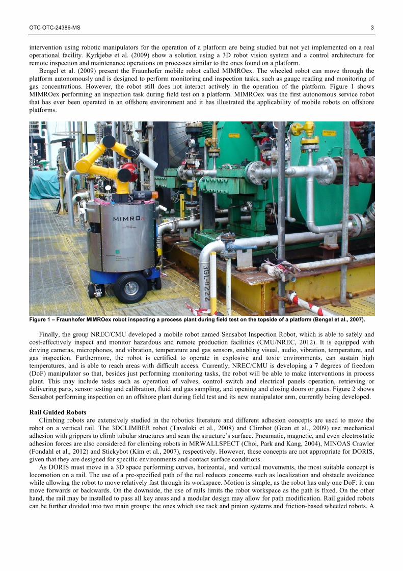
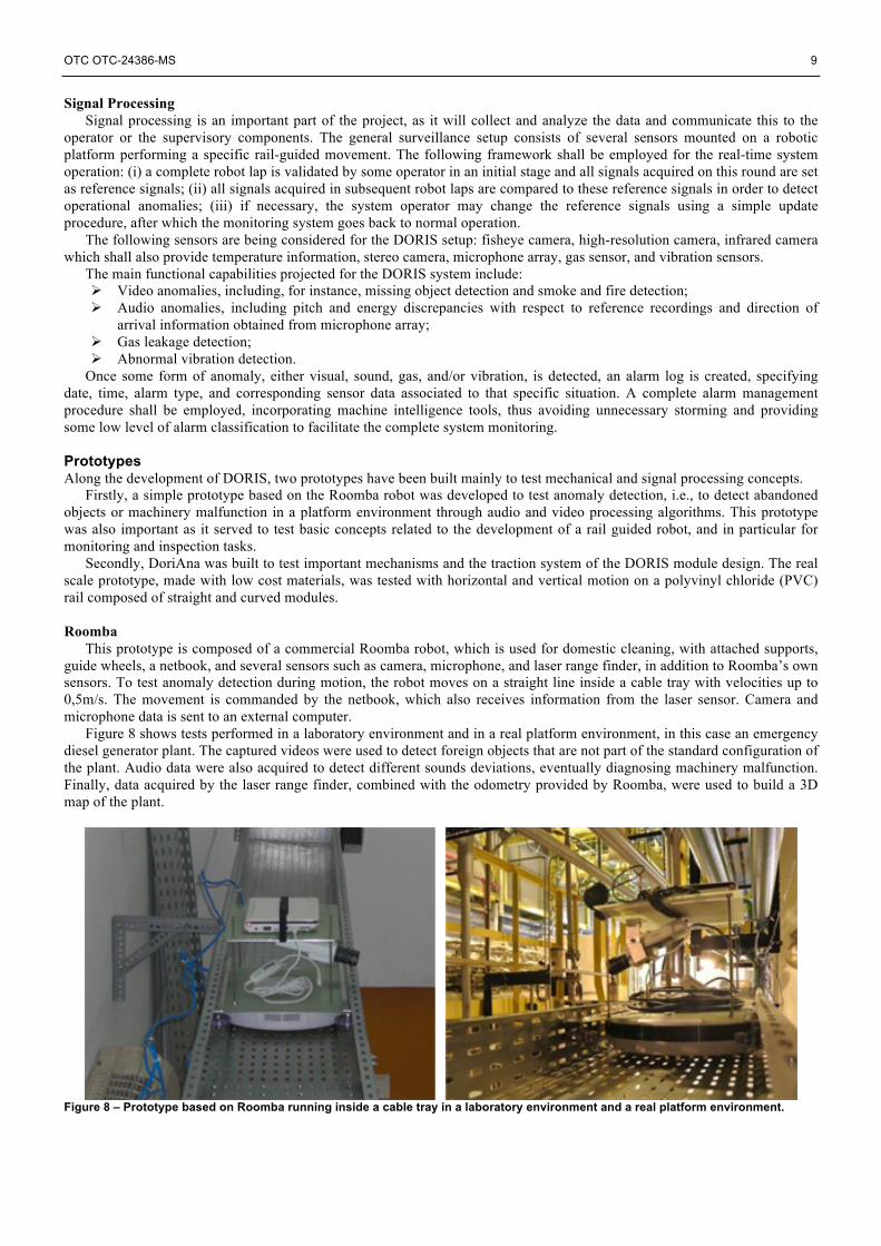
This prototype is composed of a commercial Roomba robot, which is used for domestic cleaning, with attached supports, guide wheels, a netbook, and several sensors such as camera, microphone, and laser range finder, in addition to Roomba’s own sensors. To test anomaly detection during motion, the robot moves on a straight line inside a cable tray with velocities up to 0,5m/s. The movement is commanded by the netbook, which also receives information from the laser sensor. Camera and microphone data is sent to an external computer.
Figure 8 shows tests performed in a laboratory environment and in a real platform environment, in this case an emergency diesel generator plant. The captured videos were used to detect foreign objects that are not part of the standard configuration of the plant. Audio data were also acquired to detect different sounds deviations, eventually diagnosing machinery malfunction. Finally, data acquired by the laser range finder, combined with the odometry provided by Roomba, were used to build a 3D map of the plant.
Figure 8 – Prototype based on Roomba running inside a cable tray in a laboratory environment and a real platform environment.
10 OTC OTC-24386-MS
DoriAna DoriAna is a prototype developed to test out the mechanical design of the traction module, the passive module, and the
joint that couples the two modules, as shown in Fig.4. A track is built using commercially available straight and curved tubular modules, installed in a laboratory environment. The track comprises all possible movements the robot may make.
The traction module consists of a wooden base, two sets of aluminum gimbals with polyurethane skate wheels, a machined prismatic mechanism that uses linear bearings to displace the traction wheels, and a clamping mechanism that uses a bicycle brake system to apply radial forces at the traction wheels. The passive module comprises a base with two sets of gimbals. Two joints are considered for the tests: one that uses a spring and a steel cable, and a double Cardan joint, also known as a universal joint. Figure 9 shows the traction module connected to the passive module with a double Cardan joint and the entire track installed in the laboratory.
The main objective of DoriAna is to test the following mechanical concepts: Ø The use of gimbals for guidance, stability, and weight support; Ø The traction system mounted on a prismatic mechanism; Ø The clamping system, verifying whether the applied force is sufficient to support the robot on the vertical sections; Ø The two joints used to couple the modules.
Figure 9 – Traction and passive module of DoriAna prototype moving on a horizontal curved section (top) and an image showing the entire rail (bottom).
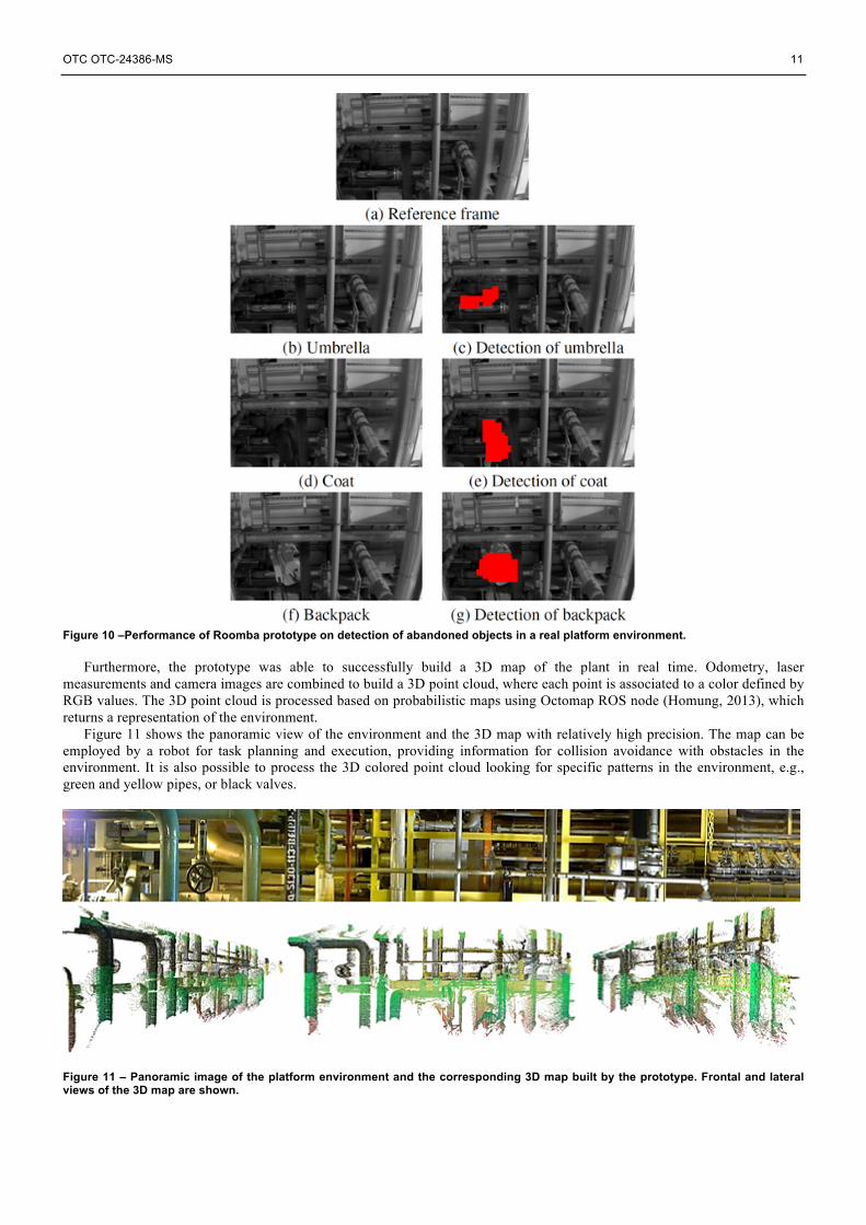
Preliminary Results Preliminary results from the Roomba prototype show that the robot was able to detect foreign objects in real time through image and video processing algorithms. The captured images were compared to reference videos with proper temporal alignment and geometric registration between the two signals. Then, changes between target and reference videos were detected using normalized cross-correlation and a temporal voting strategy along consecutive frames. Tests done in a real environment, an emergency diesel generator plant, show that the robot was able to detect three abandoned objects in a complex scene with a high level of details. Figure 10 shows reference and target images and the detection of an umbrella, a coat, and a backpack abandoned at the scene.
OTC OTC-24386-MS 11
Figure 10 –Performance of Roomba prototype on detection of abandoned objects in a real platform environment.
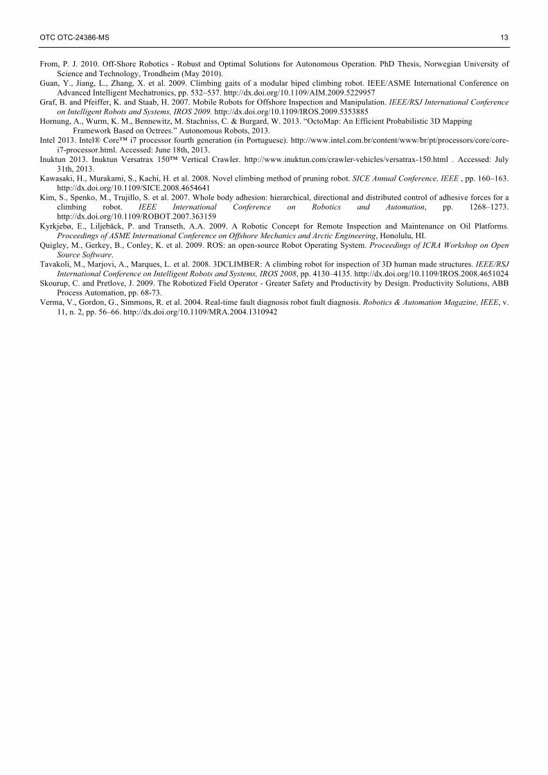
Furthermore, the prototype was able to successfully build a 3D map of the plant in real time. Odometry, laser
measurements and camera images are combined to build a 3D point cloud, where each point is associated to a color defined by RGB values. The 3D point cloud is processed based on probabilistic maps using Octomap ROS node (Homung, 2013), which returns a representation of the environment.
Figure 11 shows the panoramic view of the environment and the 3D map with relatively high precision. The map can be employed by a robot for task planning and execution, providing information for collision avoidance with obstacles in the environment. It is also possible to process the 3D colored point cloud looking for specific patterns in the environment, e.g., green and yellow pipes, or black valves.
Figure 11 – Panoramic image of the platform environment and the corresponding 3D map built by the prototype. Frontal and lateral views of the 3D map are shown.
12 OTC OTC-24386-MS
Initial tests with a newly acquired database indicate that it is possible to detect audio anomalies in the recorded signals. However, more experiments and studies need to be done. As the preliminary results point out, it is possible to do monitoring tasks at an offshore facility using a rail guided mobile robot.
Initial tests performed with DoriAna show good performance of the gimbals in terms of stability, guidance, and weight support. Even though the gimbal set may shake a little due to irregularities on the rail surface and asymmetrical positioning of the guide wheels, the base keeps steady orientation while moving. The force applied by the bicycle brake system was appropriate to hold and move the robot through vertical sections, showing that it is possible to move the robot using friction only by applying a radial force. The joint with spring and steel cable performed better than the double Cardan joint. Finally, the traction system mounted on a prismatic mechanism needs more tests and adjustments to make the movement smoother. Conclusions and Future Work In this paper, we presented the DORIS project which endeavors to develop an offshore facilities monitoring robot. Given the recent increasing attention on automation of offshore platforms by use of robots in order to improve efficiency and HSE conditions and to reduce costs, we develop a robotic system able to perform monitoring and inspection tasks in offshore environments.
The topside robot is based on rail guided modules powered by a battery system and equipped with multiple sensors that enable detection of anomalies, such as abandoned objects and gas leakage. A description of each of the five main components of DORIS has been presented.
An initial prototype, based on a Roomba robot with attached sensors, was built to prove anomaly detection under movement in a real environment similar to an offshore platform. Tests proved that the prototype was able to build a 3D map of the surrounding environment and to detect presence or absence of objects in a video stream. Also, initial tests with a newly acquired database indicate that it is possible to detect audio anomalies in the recorded signals.
Another prototype was built based on the DORIS design to test the mechanical concepts. Preliminary results showed good overall performance of the guidance system using gimbals, the possibility of using just wheels on a tubular rail to achieve vertical motion by applying radial forces, and good transmission of traction by using a joint composed of a spring and a steel cable to couple two modules.
In future works, all DORIS main systems will be built, tested, and integrated. Finally, the complete robotic mobile monitoring system composed of traction, sensing, battery, and manipulator modules, will be operated in a real environment similar to an offshore platform. It is also an aim that DORIS is to be able to perform simple intervention and sampling tasks, in addition to monitoring and inspecting the plant.
Acknowledgment The authors wish to thank all the other members of DORIS project, including Renan S. de Freitas, Lucas Carvalho, Thiago Braga, Fernando Coutinho, Amaro A. de Lima, Thiago M. Prego, Allan F. da Silva, Lucas A. Thomaz, Gabriel M. F. Ramalho, Raphael P. F. da Silva and Amanda S. D. de Loiola from the Federal University of Rio de Janeiro. We also wish to thank Auderi V. Santos, Pedro E. G. Panta and Felipe G. Noel from ALIS Tecnologia for their mechanical consulting services.
DORIS project is supported by Statoil and Petrobras, and is approved by ANP – National Agency of Petroleum, Natural Gas and Biofuels (Brazil), according to cooperation agreement number 0050.0079406.12.9.
Finally, we would like to thank the support provided by the Brazilian research funding organizations CNPQ and FAPERJ. Bibliography Anisi, D.A., Gunnar, J., Lillehagen, T. and Skourup, C. 2010. Robot Automation in Oil and Gas Facilities: Indoor and Onsite
Demonstrations. Proceedings of IEEE/RSJ International Conference on Intelligent Robots and Systems, pp. 4729–4734. http://dx.doi.org/10.1109/IROS.2010.5649281
Baghani, A., Ahmadabadi, M.N., Harati, A. 2005. Kinematics modeling of a wheel-based pole climbing robot (UT-PCR). Proceedings of IEEE International Conference on Robotics and Automation, pp. 2099–2104. http://dx.doi.org/10.1109/ROBOT.2005.1570423
Bengel, M. and Pfeiffer, K. 2007. Mimroex Mobile Maintenance and Inspection Robot for Process Plants. Fraunhofer Institute for Manufacturing Engineering and Automation IPA, pp. 1–2. http://www.care-o-bot.de/Produktblaetter/PB_300_308e.pdf (downloaded 18 July 2013).
Bengel, M., Pfeiffer, K., Graf, B. et al. 2009. Mobile Robots for Offshore Inspection and Manipulation. Proceedings of IEEE/RSJ International Conference on Intelligent Robots and Systems, pp. 3317–3322. http://dx.doi.org/10.1109/IROS.2009.5353885
Carnegie Mellon University’s National Robotics Engineering Center 2012. Sensabot: A Safe and Cost-Effective Inspection Solution. Journal of Petroleum Technology, pp. 32–34.
Christensen, L., Fischer, N., Kroffke, S. et al. 2011. Cost-Effective Autonomous Robots for Ballast Water Tank Inspection. Journal of ship production and design, v. 27, n. 3, pp. 127–136.
Choi, H., Park, J. and Kang, T. 2004. A self-contained wall climbing robot with closed link mechanism. KSME international journal, v. 18, n. 4, pp. 573–581. http://dx.doi.org/10.1007/BF02983641
Digia 2013. Qt Project. http://qt-project.org/ . Accessed: July 31th, 2013. Fauroux, J.C. and Morillon, J. 2010. Design of a climbing robot for cylindro-conic poles based on rolling self-locking. Industrial Robot: An
International Journal, v. 37, n. 3, pp. 287–292. http://dx.doi.org/10.1108/01439911011037695 Fondahl, K., Eich, M., Wollenberg, J. et al. 2012. A Magnetic Climbing Robot for Marine Inspection Services. Proceedings of 11th
International Conference on Computer and IT Applications in the Maritime Industries, COMPIT 2012.
OTC OTC-24386-MS 13
From, P. J. 2010. Off-Shore Robotics - Robust and Optimal Solutions for Autonomous Operation. PhD Thesis, Norwegian University of Science and Technology, Trondheim (May 2010).
Guan, Y., Jiang, L., Zhang, X. et al. 2009. Climbing gaits of a modular biped climbing robot. IEEE/ASME International Conference on Advanced Intelligent Mechatronics, pp. 532–537. http://dx.doi.org/10.1109/AIM.2009.5229957
Graf, B. and Pfeiffer, K. and Staab, H. 2007. Mobile Robots for Offshore Inspection and Manipulation. IEEE/RSJ International Conference on Intelligent Robots and Systems, IROS 2009. http://dx.doi.org/10.1109/IROS.2009.5353885
Hornung, A., Wurm, K. M., Bennewitz, M. Stachniss, C. & Burgard, W. 2013. “OctoMap: An Efficient Probabilistic 3D Mapping Framework Based on Octrees.” Autonomous Robots, 2013.
Intel 2013. Intel® Core™ i7 processor fourth generation (in Portuguese). http://www.intel.com.br/content/www/br/pt/processors/core/core-i7-processor.html. Accessed: June 18th, 2013.
Kawasaki, H., Murakami, S., Kachi, H. et al. 2008. Novel climbing method of pruning robot. SICE Annual Conference, IEEE , pp. 160–163. http://dx.doi.org/10.1109/SICE.2008.4654641
Kim, S., Spenko, M., Trujillo, S. et al. 2007. Whole body adhesion: hierarchical, directional and distributed control of adhesive forces for a climbing robot. IEEE International Conference on Robotics and Automation, pp. 1268–1273. http://dx.doi.org/10.1109/ROBOT.2007.363159
Kyrkjebø, E., Liljebäck, P. and Transeth, A.A. 2009. A Robotic Concept for Remote Inspection and Maintenance on Oil Platforms. Proceedings of ASME International Conference on Offshore Mechanics and Arctic Engineering, Honolulu, HI.
Quigley, M., Gerkey, B., Conley, K. et al. 2009. ROS: an open-source Robot Operating System. Proceedings of ICRA Workshop on Open Source Software.
Tavakoli, M., Marjovi, A., Marques, L. et al. 2008. 3DCLIMBER: A climbing robot for inspection of 3D human made structures. IEEE/RSJ International Conference on Intelligent Robots and Systems, IROS 2008, pp. 4130–4135. http://dx.doi.org/10.1109/IROS.2008.4651024
Skourup, C. and Pretlove, J. 2009. The Robotized Field Operator - Greater Safety and Productivity by Design. Productivity Solutions, ABB Process Automation, pp. 68-73.
Verma, V., Gordon, G., Simmons, R. et al. 2004. Real-time fault diagnosis robot fault diagnosis. Robotics & Automation Magazine, IEEE, v. 11, n. 2, pp. 56–66. http://dx.doi.org/10.1109/MRA.2004.1310942