50
USER MANUAL OTDR-30A Optical Time-Domain Reflectometer Version 1.0 2005/12
USER MANUAL OTDR-30A Optical Time-Domain Reflectometer
Version 1.02005/12

User’s Manual for OTDR-30A
- i -
Notices
Copyright© 2005 CTC Union Technologies. All rights reserved. No part of this manual may be reproduced in any form or by any means (including electronic storage and retrieval or translation into a foreign language) without prior agreement and written consent from CTC Union Technologies, as governed by international copyright laws.
Warranty
The material contained in this document is subject to change without notice. CTC Union Technologies makes no warranty of any kind with regard to this material, including, but not limited to, the implied warranties of merchantability and fitness for a particular purpose. CTC Union Technologies shall not be liable for errors contained herein or for incidental or consequential damages in connection with furnishing, performance, or use of this material. The battery is a consumable part and is not subject to the OTDR-30A warranty.
Edition/print data
All Editions and Updates of this manual and their creation dates are listed below. First Edition……………April 2004 Second Edition…………December 2005
ISO 9001 Certification Produced to ISO9001 International Quality System Standard as part of CTC Union Technologies, objective of continually increasing customer satisfaction through improved process control.
User’s Manual for OTDR-30A
- ii -
Safety Instructions
During each stage of operation of this instrument, please always observe the following safety instructions. Not taking any safety precautions or following the instructions will violate the safety standards of design, manufacturing and application of these instruments. In no case will CTC Union Technologies bear the responsibilities for consequences incurred by violation of the following instructions. GENERAL This product is a Safety Class 3 instrument. The protective features of this product may be impaired if it is used in a manner not specified in the operation instrument. Environmental conditions
This instrument (without AC Adapter) is intended for outdoor use in an installation category Ⅱ, pollution degree 2 environment. It is designed to operate at a maximum relative humidity of 95% and at altitudes of up to 2000 meters. Refer to the specifications tables. Before applying power
Verify that the product is set to match the available line voltage, the correct fuse is installed, and all safety precautions are taken. Note the instrument’s external markings described under Symbols. Fuses
Only fuses with the required rated current, voltage, and specified type (normal blow, time delay, etc.) should be used. Do not use repaired fuses or short-circuited fuse holders. To do so could cause a shock or fire hazard. Do not operate in an explosive atmosphere
Do not operate the instrument in the presence of flammable gases or fumes.

User’s Manual for OTDR-30A
- iii -
Do not remove the instrument cover
Operating personnel must not remove instrument covers. Component replacement and internal adjustments must be made only by qualified service personnel. Instrument that appears damaged or defective should be made inoperative and secured against unintended operation until they can be repaired by qualified service personnel.
Safety Terms Used in This Manual
The WARNING sign denotes a hazard. It calls attention to a procedure, practice, or the like, which, if not correctly performed or adhered to, could result in personnel injury. Do not proceed beyond a WARNING sign until the indicated conditions are fully understood and met.
The CAUTION sign denotes a hazard. It calls attention to an operating procedure, or the like, which, if not correctly performed or adhered to, could result in damage to or destruction of part or all of the product. Do not proceed beyond a CAUTION sign until the indicated conditions are fully understood and met.
The NOTE sign information that may be beneficial during the use and maintenance of the instrument.
OTDR-30A is a laser instrument. Users should avoid looking directly into the
optic output. And the use of microscope or magnifier should also be avoided, for the use of such devices can focus a highly intense beam onto the retina, which may result in permanent eye damage.
Make sure that the optical fiber or cable is not in use and there is no laser beam in the fiber before testing via OTDR-30A. Otherwise, it may result in imprecise test trace, even permanent damage to the OTDR-30A.

User’s Manual for OTDR-30A
- iv -
Battery: Battery for this instrument is rechargeable NiMH battery. If unused for a long time, battery should be recharged before being used. If the instrument is left idle for more than two months, it should be recharged to maintain adequate battery volume. Do not recharge batteries for more than 8 hours. Do not take batteries out without technical staff’s help. Do not expose batteries to fire or intense heat. Do not open or mutilate batteries. Avoid touching the electrolyte in the batteries, which is corrosive and may cause injuries to eyes, skin or damage to clothes. External Power: This instrument from CTC Union supports external power. Power requirements: DC 13.8V/1.2A.
Laser Radiation: To avoid serious eye injury, never look directly into the optical outputs of fiber optic network equipment, test equipment, patch cords, or test jumpers.
Always avoid looking directly into the optical output port, when the instrument is working.
Always replace protective dust cap on the detector port when the instrument is not being used.
Always avoid looking directly at unconnected end of optic fiber in testing and make the unconnected end point at a non-reflective object, if possible.
User’s Manual for OTDR-30A
- v -
Table of Contents
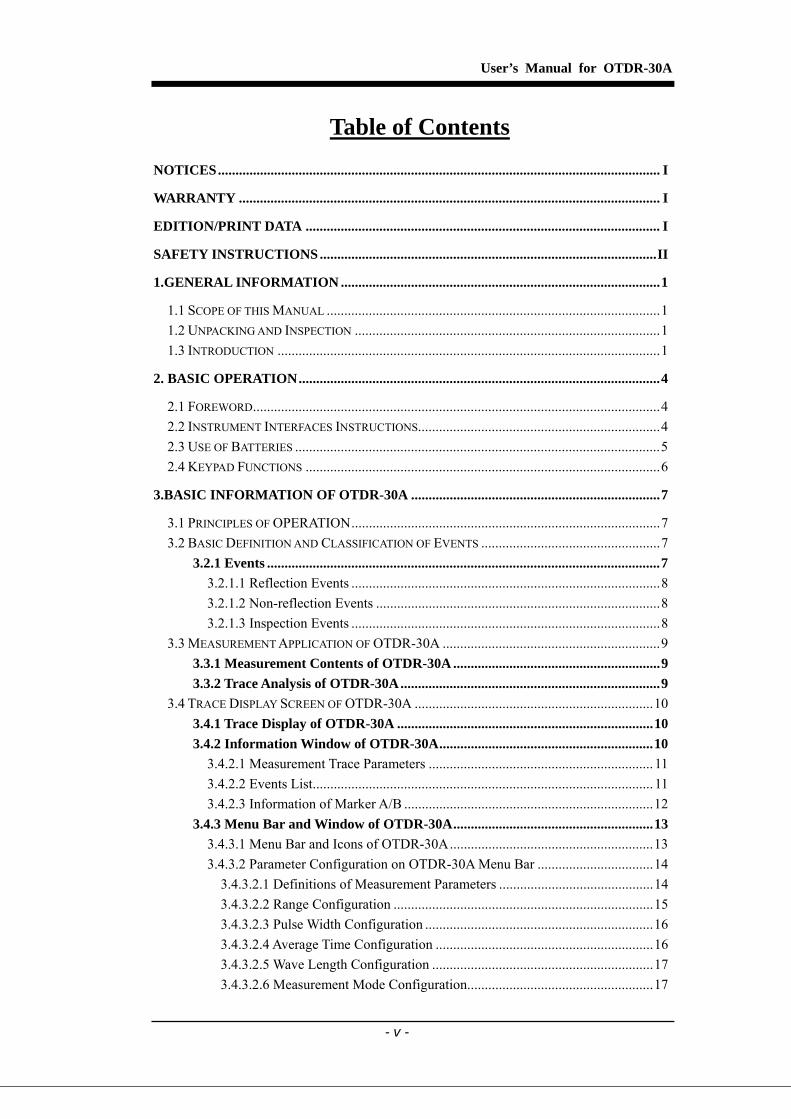
NOTICES.............................................................................................................................. I
WARRANTY ........................................................................................................................ I
EDITION/PRINT DATA ..................................................................................................... I
SAFETY INSTRUCTIONS................................................................................................II
1.GENERAL INFORMATION ...........................................................................................1
1.1 SCOPE OF THIS MANUAL ...............................................................................................1 1.2 UNPACKING AND INSPECTION .......................................................................................1 1.3 INTRODUCTION .............................................................................................................1
2. BASIC OPERATION.......................................................................................................4
2.1 FOREWORD....................................................................................................................4 2.2 INSTRUMENT INTERFACES INSTRUCTIONS.....................................................................4 2.3 USE OF BATTERIES ........................................................................................................5 2.4 KEYPAD FUNCTIONS .....................................................................................................6
3.BASIC INFORMATION OF OTDR-30A .......................................................................7
3.1 PRINCIPLES OF OPERATION........................................................................................7 3.2 BASIC DEFINITION AND CLASSIFICATION OF EVENTS ...................................................7
3.2.1 Events ................................................................................................................7 3.2.1.1 Reflection Events ........................................................................................8 3.2.1.2 Non-reflection Events .................................................................................8 3.2.1.3 Inspection Events ........................................................................................8
3.3 MEASUREMENT APPLICATION OF OTDR-30A ..............................................................9 3.3.1 Measurement Contents of OTDR-30A ...........................................................9 3.3.2 Trace Analysis of OTDR-30A..........................................................................9
3.4 TRACE DISPLAY SCREEN OF OTDR-30A ....................................................................10 3.4.1 Trace Display of OTDR-30A .........................................................................10 3.4.2 Information Window of OTDR-30A.............................................................10
3.4.2.1 Measurement Trace Parameters ................................................................ 11 3.4.2.2 Events List................................................................................................. 11 3.4.2.3 Information of Marker A/B .......................................................................12
3.4.3 Menu Bar and Window of OTDR-30A.........................................................13 3.4.3.1 Menu Bar and Icons of OTDR-30A..........................................................13 3.4.3.2 Parameter Configuration on OTDR-30A Menu Bar .................................14
3.4.3.2.1 Definitions of Measurement Parameters ............................................14 3.4.3.2.2 Range Configuration ..........................................................................15 3.4.3.2.3 Pulse Width Configuration .................................................................16 3.4.3.2.4 Average Time Configuration ..............................................................16 3.4.3.2.5 Wave Length Configuration ...............................................................17 3.4.3.2.6 Measurement Mode Configuration.....................................................17

User’s Manual for OTDR-30A
- vi -
3.4.3.2.7 IOR Configuration..............................................................................18 3.4.3.2.8 Scatter Coefficient Configuration.......................................................19 3.4.3.2.9 Non Reflection Threshold Configuration ...........................................19 3.4.3.2.10 Reflection Threshold Configuration.................................................20 3.4.3.2.11 End Threshold Configuration ...........................................................20 3.4.3.2.12 Delete File ........................................................................................21 3.4.3.2.13 Time Configuration ..........................................................................21 3.4.3.2.14 Auto off Configuration .....................................................................22 3.4.3.2.15 Language Configuration...................................................................22 3.4.3.2.16 Contrast Adjustment of LCD Display ..............................................23 3.4.3.2.17 Color Mode Setting ..........................................................................24 3.4.3.2.18 Defaults Set ......................................................................................24 3.4.3.2.19 Help ..................................................................................................25
3.5 BATTERY RECHARGE STATUS......................................................................................26
4. TRACE MEASUREMENT AND PROCESSING OF EXISTING TRACES ...........27
4.1 INSTRUCTIONS ON GUI ...............................................................................................27 4.2 TRACE MEASUREMENT OF OTDR-30A ......................................................................28
4.2.1 Trace Measurement- Connect Optical Fiber ...............................................28 4.2.2 Trace Measurement - Parameter Configuration .........................................28 4.2.3 Trace Measurement- Auto .............................................................................28 4.2.4 Trace Measurement - Manual .......................................................................30 4.2.5 Trace Measurement -Reasons of Measurement Failures ............................30
4.3 INFORMATION WINDOW ..............................................................................................30 4.3.1 Switch between Information Window Items................................................30 4.3.2 Review Event List...........................................................................................31 4.3.3 Review Marker A/B Information..................................................................31 4.3.3.1 Switching between Marker A/B .................................................................31 4.3.3.2 Information between Marker A/B .............................................................31
4.4 ZOOM OUT TRACE HORIZONTALLY .............................................................................32 4.5 ZOOM IN TRACE HORIZONTALLY ................................................................................32 4.6 ZOOM OUT TRACE VERTICALLY ..................................................................................32 4.7 ZOOM IN TRACE VERTICALLY .....................................................................................32 4.8 SAVE TRACE................................................................................................................33 4.9 BROWSE SAVED TRACES .............................................................................................33 4.10 UPLOAD SAVED TRACES ...........................................................................................34
A. MAINTENANCE AND CALIBRATION....................................................................36
MAINTENANCE OF BATTERIES ..........................................................................................36 CLEANING OF INTERFACES................................................................................................36
Effects of Cleaning Interfaces and Connectors.............................................36 Safety instructions to be followed before cleaning.......................................37 Tools for Cleaning Interfaces and Connectors..............................................37 Preferred Procedure for Cleaning Interfaces and Connectors.......................37
CALIBRATION REQUIREMENTS..........................................................................................37
User’s Manual for OTDR-30A
- vii -
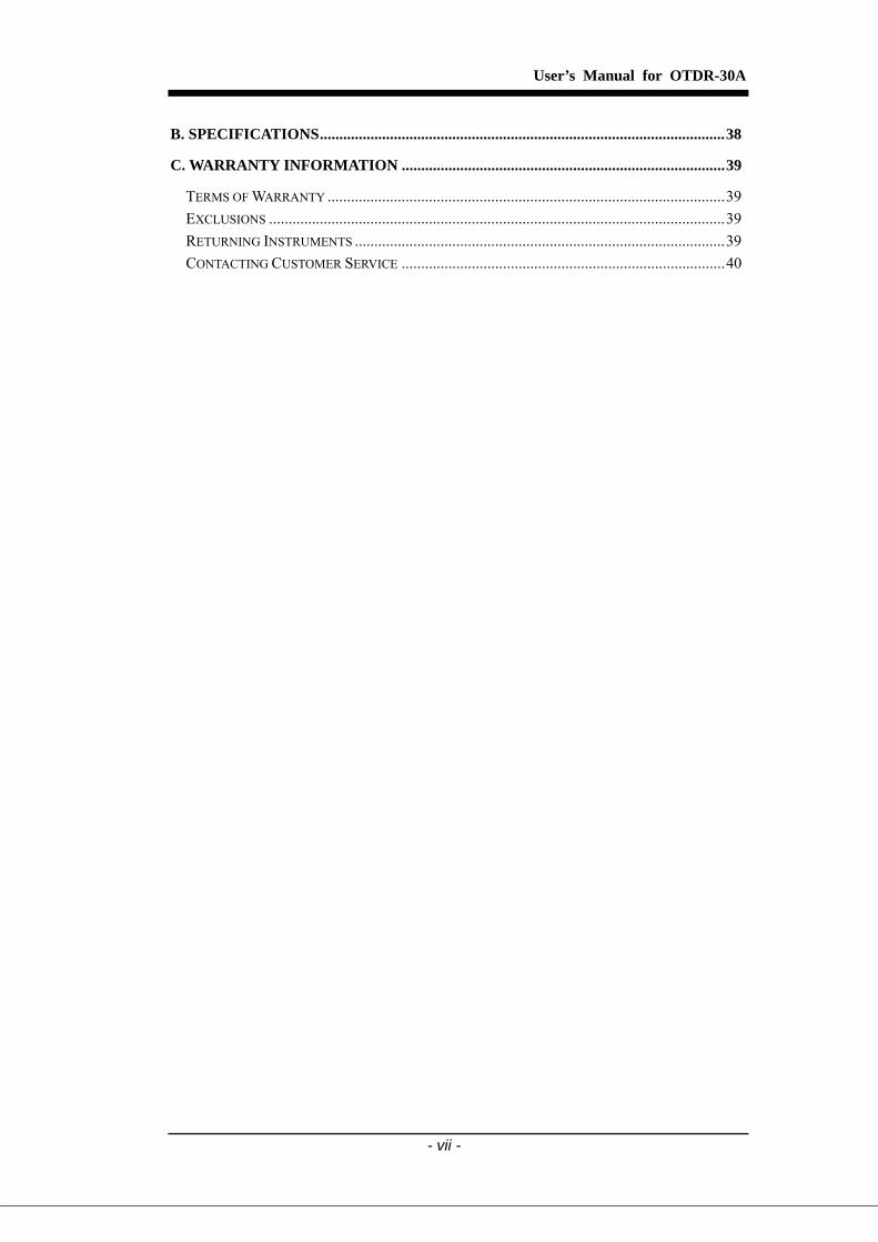
B. SPECIFICATIONS........................................................................................................38
C. WARRANTY INFORMATION ...................................................................................39
TERMS OF WARRANTY ......................................................................................................39 EXCLUSIONS .....................................................................................................................39 RETURNING INSTRUMENTS ...............................................................................................39 CONTACTING CUSTOMER SERVICE ...................................................................................40

User’s Manual for OTDR-30A
- viii -
Table of Figures Figure 1. Connectors of OTDR-30A .....................................................................................4 Figure 2. Operation Keys of OTDR-30A ................................................................................6 Figure 3. Reflection Event.......................................................................................................8 Figure 4. Non-reflection Event................................................................................................8 Figure 5. Trace Display Screen .............................................................................................10 Figure 6. Traces and Coordinates ..........................................................................................10 Figure 7.(a) Measurement Trace Parameters ......................................................................... 11 Figure 7.(b) Analysis Trace Parameters................................................................................. 11 Figure 8. Events List .............................................................................................................12 Figure 9. Information of Marker A/B ....................................................................................12 Figure 10.(a) Parameter Configuration..................................................................................14 Figure 10. (b) Parameter Configuration ................................................................................14 Figure 11. Set Range .............................................................................................................15 Figure 12. Pulse Width Configuration...................................................................................16 Figure 13. Average Time Configuration ................................................................................17 Figure 14. Wavelength Configuration ...................................................................................17 Figure 15 Measurement Mode Configuration .......................................................................18 Figure 16. IOR Configuration ...............................................................................................18 Figure 17. Scatter Coefficient Configuration ........................................................................19 Figure 18. Non Reflection Threshold ....................................................................................19 Figure 19. Reflection Threshold Configuration.....................................................................20 Figure 20. End Threshold Configuration...............................................................................21 Figure 21. Delete File............................................................................................................21 Figure 22 Time Configuration ...............................................................................................22 Figure 23. Auto Off Configuration ........................................................................................22 Figure 24. Language Configuration ......................................................................................23 Figure 25. Contrast Adjustment of LCD Display ..................................................................23 Figure 26. Color Mode Setting..............................................................................................24 Figure 27. Load Defaults.......................................................................................................24 Figure 28. (a) Help ................................................................................................................25 Figure 28. (b) Help ................................................................................................................25 Figure 28. © Help..................................................................................................................25 Figure 29. Power on Interface ...............................................................................................27 Figure 30. Quick Reference...................................................................................................27 Figure 31.(a) Measuring ........................................................................................................29 Figure 31.(b) Measuring........................................................................................................29 Figure 32. Trace Measurement of OTDR-30A......................................................................30 Figure 33. Save Trace............................................................................................................33 Figure 34. Browse Saved Traces ...........................................................................................34 Figure 35. Upload Saved Traces............................................................................................34 Figure 36. Structure of Flange...............................................................................................37
User’s Manual for OTDR-30A
- 1 -
1.General Information
1.1 Scope of this Manual
Thank you for purchasing this CTC Union instrument. Please read this manual carefully before using this CTC Union series fiber-optic instrument. Always observe the warnings and cautions appearing throughout this manual. This manual contains the information necessary for proper operation and maintenance of CTC Union OTDR-30A, troubleshooting instructions as well as information regarding obtaining services. The OTDR-30A is carefully assembled and has undergone a rigorous mechanical, electrical, and optical inspection prior to shipment. Besides the instrument, the package should also include a data transfer cable, a power adapter, a PC Analysis software installation disk and this users’ manual. For detailed information, refer to the packing list. Upon receiving the instrument, please check for any obvious signs of physical damage that may have occurred during shipment. Report any damage to the shipping agent or the representative of CTC Union Technologies immediately. Retain the original packing materials in case reshipment becomes necessary.
1.2 Unpacking and Inspection
This instrument has been carefully packed in accordance with standard shipping procedures. Examine the instrument for damage that may have occurred during shipment. If you find any damage or the instrument is not working, or if any of the following items are not included, please contact your representative of CTC Union Technologies. If support is necessary, you may contact CTC Union Technologies, Inc via this email: [email protected]
1.3 Introduction
OTDR-30A is the preferred choice for the measurement of optical fiber’s specifications. With OTDR, you can make assessment of one single optical fiber or a whole optical fiber chain. Specifically, you can directly observe loss and events distribution of optical fiber chain.
The OTDR-30A will check the transmission quality of optic fiber through measurement of backward scattered lights. Standard organizations such as the

User’s Manual for OTDR-30A
- 2 -
International Telecom Union (ITU) define backward scattered lights as effective analysis means of measurement of optical fiber loss. Backward scattering is also the only effective way of connector inspection, which can be applied to measure the length of optical fiber, as well. Therefore, OTDR-30A is a useful tool for optical fiber manufacturing, installation and maintenance. OTDR-30A works through reviewing “events” in optical fiber (for example, irregularities and connectors), which are quite helpful for quality control for those who are in charge of optical fiber manufacturing, installation and maintenance. OTDR-30A can help identify the irregularities in optical fiber, locate them, and measure their attenuation, relevant loss and their homogeneity. OTDR-30A is even more helpful for field operation. It can help to check the qualification of optical fiber chain circuit on a regular basis. For the purpose of future maintenance, transmission quality and condition of optical fiber need to be recorded and stored, which includes measurement of optical path, total loss, and loss of all tie-ins and connectors. Additionally, the OTDR-30A is easy to use, small and compact. According to the ergonomics, it is designed to fully embody the user's convenience with its large color LCD display and graphical interface. It can save and transfer the measurement curves data to a PC by the provided software for further analyzing, reporting and printing. OTDR-30A features:
Basic applications: a) Measure the length of optical fiber and cable b) Measure the distance between two points on optical fiber and cable c) Locate faults and ruptures of optical fiber and cable d) Display distribution curve of optical fiber and cable loss e) Measure attenuation coefficient of optical fiber and cable f) Measure loss between two points on optical fiber and cable g) Measure loss of tie-ins h) Measure reflection of reflection events of optical fiber and cable
User’s Manual for OTDR-30A
- 3 -
For a specific event (transmission quality changed due to faults caused by welding, connector, bending etc.), the following measurements can be carried out with OTDR-30A:
a) For each event: distance, loss and reflection; b) For each section of optical fiber: length and loss of dB or dB/Km; c) For the whole optical fiber chain: length and loss of dB;
Large Color LCD display with auto or manual adjustment of contrast Backlight LCD display supports night operation Easy operation with trace graphic display Trace storage function RS232/USB Data upload port PC analysis software for analyzing and reporting previously stored data Auto off function conserving battery life DC/AC power supply Auto recharging, 5 hours operation for one charge.
User’s Manual for OTDR-30A
- 4 -
2. Basic Operation
2.1 Foreword
This chapter introduces the basic operation on the OTDR-30A. Specific operations of this instrument are elaborated in Chapter 3 of this manual. Please read this manual carefully for optimal operation. Should you encounter any problems during operation, you are welcome to contact the technical staff of our company or representatives.
2.2 Instrument Interfaces Instructions
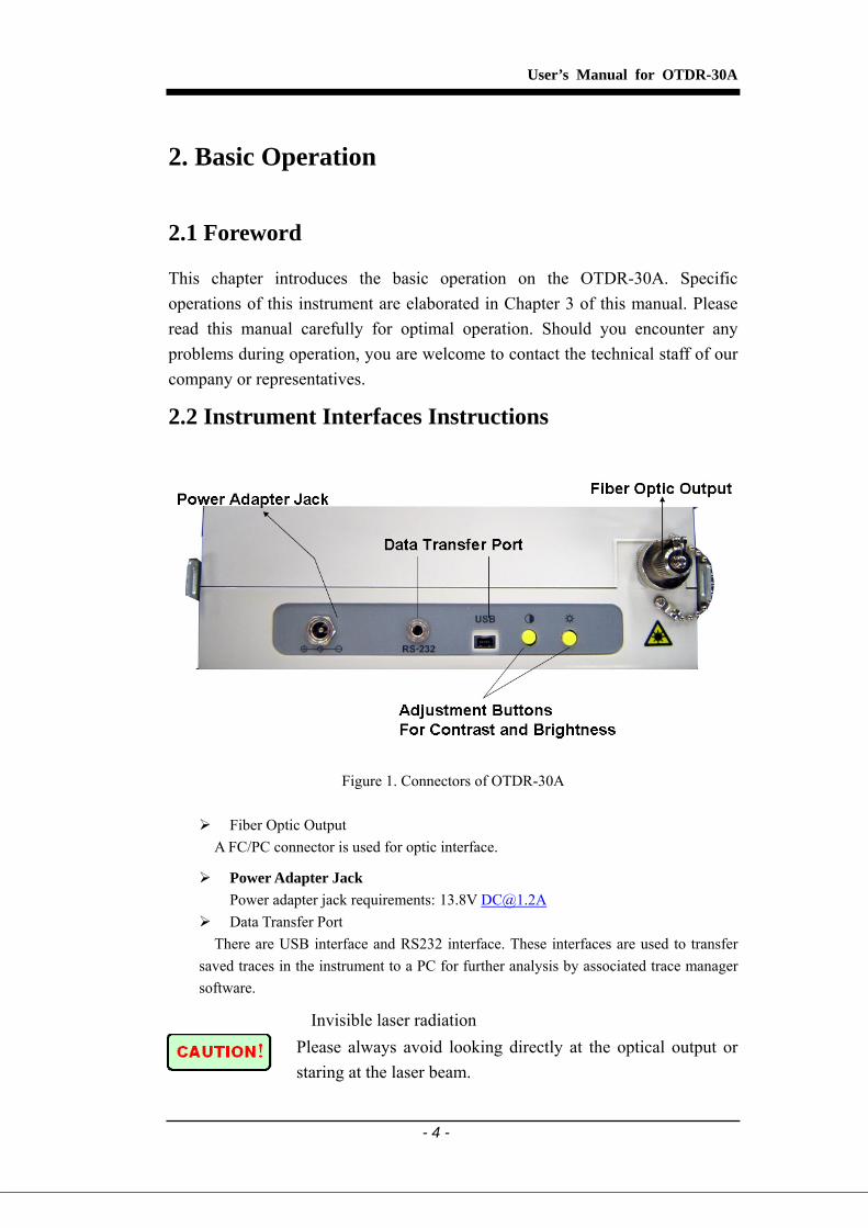
Figure 1. Connectors of OTDR-30A
Fiber Optic Output A FC/PC connector is used for optic interface.
Power Adapter Jack Power adapter jack requirements: 13.8V [email protected]
Data Transfer Port There are USB interface and RS232 interface. These interfaces are used to transfer
saved traces in the instrument to a PC for further analysis by associated trace manager software.
告 Invisible laser radiation Please always avoid looking directly at the optical output or staring at the laser beam.

User’s Manual for OTDR-30A
- 5 -
2.3 Use of Batteries
Battery for CTC Union Technologies OTDR-30A is a NiMH type battery. All the NiMH batteries have been correctly installed and gone thorough precise debugging. Please do not open the instrument to replace batteries.
Cautions during Operation: The following may cause auto power off of the instrument:
The instrument will auto power off when there is insufficient power during operation and low power will be shown on the LCD.
If unused for a long time and cause insufficient power, the instrument will be power off several seconds after powering on so as to protect the batteries in case of excessive discharging. The internal batteries should be recharged immediately through adapter.
Cautions in Recharge: Quick charge is needed first and then switch to trickle charge after the
voltage reaches a predefined Figure. Quick charge temperature is
+5~+45℃, and trickle charge temperature is 0~+55℃, suitable for
indoors. Battery will not reach full or may be damaged if the charging temperature is beyond the above range, which may shorten battery life.
3 hours for quick charge;
Do not charge for over 8 hours

User’s Manual for OTDR-30A
- 6 -
2.4 Keypad Functions
Figure 2. Operation Keys of OTDR-30A
[On/Off]
Power on or off.
[ ] Under GUI, Press to start measurement. While testing, press this key to stop
measurement.
[Enter]
Under GUI, press this key to confirm the current operation; [ ] [ ]
Main functions: Move menu bar in menu operation; Highlight the icon to be operated; Adjust parameter in parameter;
[ ][ ]
Main functions: Select parameter to be adjusted in parameter configuration; Move marker leftwards or rightwards in Trace operation; Turn page while in Help sub-menu.
[Quit]
Main functions:
Read help when power on Cancel the current operation; Exit menu configuration; Switch between information Windows;
User’s Manual for OTDR-30A
- 7 -
3.Basic Information of OTDR-30A
3.1 Principles of Operation
OTDR (Optical Time Domain Reflectometer) is a measurement instrument for identifying optic fiber transmission features. The instrument is mainly used to measure attenuation of a whole optic fiber chain and provide attenuation details relating to length, namely detect, locate and measure any event in optic fiber chain (events refer to faults caused by welding, connectors, and bending whose transmission change can be measured). Its non-destructive, one-end connection, and rapid measurement has made the OTDR-30A an indispensable tool for manufacture, construction, and maintenance of optic fiber. The faults and heterogeneity of optic fiber itself cause Rayleigh scattering of light pulse transmitted in optic fiber. Part of light pulse is scattered in the reverse direction, and this is called Rayleigh backward scattering, which actually provides attenuation details relating to length. Information relating to distance is obtained through time information (that’s the reason why there is “time Domain” in the name of OTDR). Fresnel reflection occurs at the boundary between two media of different IOR (for example, connections of faults, connectors, or optic fiber end). This reflection is used to locate the discontinuous points on optic fiber. The magnitude of reflection depends on the difference between IOR and the smoothness of boundary. OTDR sends out a light pulse into connected optic fiber, and receive reflections of events and backward scattering power of pulse in time. Locus will be displayed on LCD. The y-axis is dB value of backward scattering power, and the x-axis is the distance.
3.2 Basic Definition and Classification of Events
3.2.1 Events Events refer to any abnormal points causing attenuation or sudden change of scattering power besides the normal scattering of optic fiber, which include all kinds of losses like bending, connections and ruptures. Events points displayed on LCD are abnormal points that cause traces to deviate from straight line. Events can be classified as reflection events and non-reflection events.
User’s Manual for OTDR-30A
- 8 -
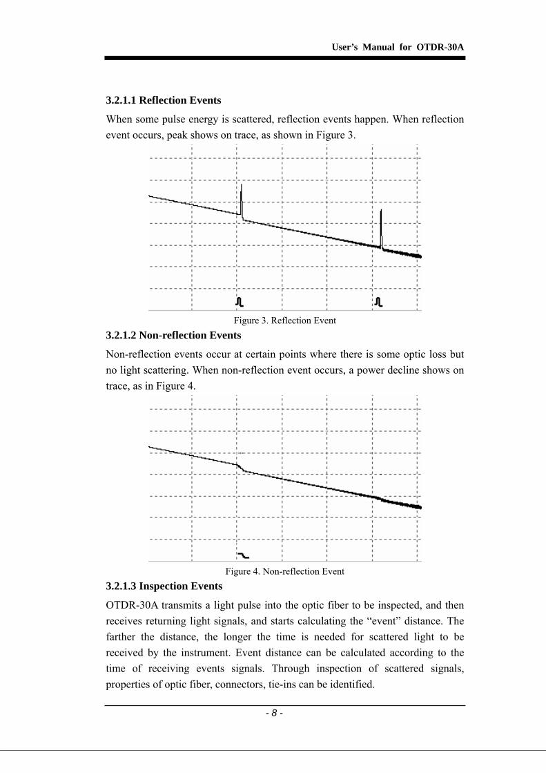
3.2.1.1 Reflection Events
When some pulse energy is scattered, reflection events happen. When reflection event occurs, peak shows on trace, as shown in Figure 3.
Figure 3. Reflection Event
3.2.1.2 Non-reflection Events
Non-reflection events occur at certain points where there is some optic loss but no light scattering. When non-reflection event occurs, a power decline shows on trace, as in Figure 4.
Figure 4. Non-reflection Event
3.2.1.3 Inspection Events
OTDR-30A transmits a light pulse into the optic fiber to be inspected, and then receives returning light signals, and starts calculating the “event” distance. The farther the distance, the longer the time is needed for scattered light to be received by the instrument. Event distance can be calculated according to the time of receiving events signals. Through inspection of scattered signals, properties of optic fiber, connectors, tie-ins can be identified.
User’s Manual for OTDR-30A
- 9 -
3.3 Measurement Application of OTDR-30A
OTDR-30A displays power relating to distance of returning signals. This information can be used to identify the main properties of an optic fiber chain.
3.3.1 Measurement Contents of OTDR-30A Event location (distance), end or rupture of optic fiber chain Attenuation coefficient of fiber Loss of a single event (for example, one optic tie-in), or total loss from upper end
to end Range of a single event like reflection of connectors (or grade of reflection) Auto measurement of cumulative loss of a single event
3.3.2 Trace Analysis of OTDR-30A The trace analysis of OTDR-30A is fully automatic. The trace locates:
Reflection events of connections and mechanic tie-ins Non-reflection events (usually at welding tie-ins) End of optic fiber
Through scanning the first loss event that is larger than end threshold, end of optic fiber can be identified.
Events list:event type, loss, reflection and distance.
User’s Manual for OTDR-30A
- 10 -
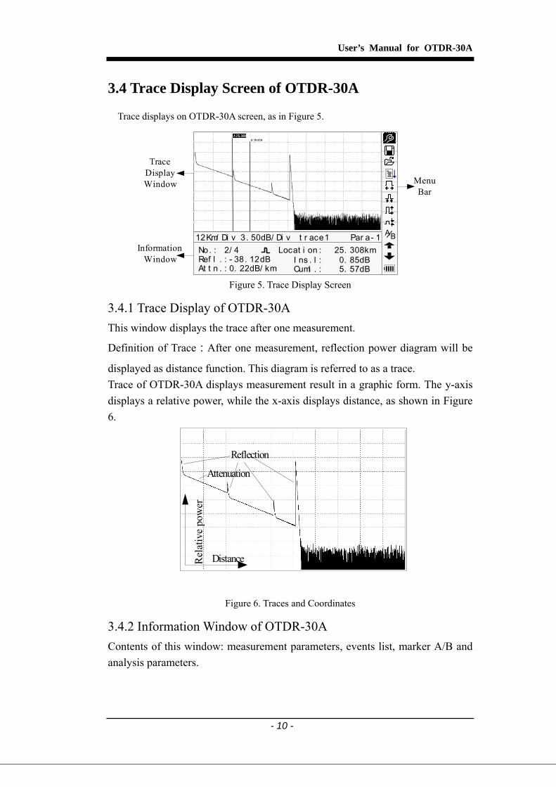
3.4 Trace Display Screen of OTDR-30A
Trace displays on OTDR-30A screen, as in Figure 5.
12Km/ Di v 3. 50dB/ Di v t r ace1 Par a- 1No. : 2/ 4
At t n . : 0. 22dB/ km
Locat i on : 25. 308kmRef l . : - 38. 12dB I ns . l : 0. 85dB
Cuml . : 5. 57dB
Menu Bar
TraceDisplayWindow
InformationWindow
BA
Figure 5. Trace Display Screen
3.4.1 Trace Display of OTDR-30A This window displays the trace after one measurement.
Definition of Trace:After one measurement, reflection power diagram will be
displayed as distance function. This diagram is referred to as a trace. Trace of OTDR-30A displays measurement result in a graphic form. The y-axis displays a relative power, while the x-axis displays distance, as shown in Figure 6.
Reflection
Attenuation
Rel
ativ
e po
wer
Distance
Figure 6. Traces and Coordinates
3.4.2 Information Window of OTDR-30A Contents of this window: measurement parameters, events list, marker A/B and analysis parameters.

User’s Manual for OTDR-30A
- 11 -
3.4.2.1 Measurement Trace Parameters
Important measurement and analysis parameters always display in the information window. as shown in Figure 7.(a), (b):
BA
30s80km1. 4659
2. 5us1550nm
Ave. Ti me:Range:I OR :
Pul sewi dt h :Wavel engt h :
12Km/ Di v 3. 50dB/ Di v t r ace 1 Par a- 1
Figure 7.(a) Measurement Trace Parameters
Me a s . Da t e: 27- May - 2005 09 : 15NRef l . Thr e . :
- 52. 00Ref l . Thr e . :3. 00End Thr e . :- 51. 50
0. 20Scat . Coef . :
12Km/ Di v 3. 50dB/ Di v t r ace1 Par a - 2 BA
Figure 7.(b) Analysis Trace Parameters
For definitions and configurations of items in Figure 7.(a) (Avg. time, Range, IOR, wave length and pulse width) shown in the interface, please refer to parameter configuration. For definitions of items in Figure 7.(b) (date, reflection threshold, non-reflection threshold, end threshold, scattering coefficient), please refer to parameter configuration. 3.4.2.2 Events List
Any defined posts will be displayed in the event list. For example, non-reflection event like welding points and reflection event like connectors, are shown in Figure 8.

User’s Manual for OTDR-30A
- 12 -
No. : 2/ 4
At t n . : 0 . 22dB/ km
Locat i on : 25 . 308kmRef l . : - 38 . 12dB I ns . L. : 0. 85dB
Cum. L. : 5. 57dB
12Km/ Di v 3. 50dB/ Di v t r ace 1 Event BA
Figure 8. Events List
No: Event sequence No;
Four types of events: Begin ; Reflection event; Fiber end; Attenuation event;
Loc.:Distance from beginning point to event;
Refl.:Magnitude of reflection;
Insl.:Loss of Inserted event;
Attn.:Attenuation characteristic from one event point to the current event.
Cuml.:Cumulative loss, calculating from beginning point to the current event.
3.4.2.3 Information of Marker A/B
Markers are used to mark and analyze a single event, trace section and distance. Distance, attenuation, loss at marker or between markers will be displayed in information of markers, as in Figure 9.
A- B: 9. 274km1. 71dB0. 18dB/ km
2Pt . Loss :2Pt . At t en :
12Km/ Di v 3. 50dB/ Di v t r ace1 Mar ker BA
Figure 9. Information of Marker A/B
The following parameters are measured between marker A and B. When you change either marker, the record will change accordingly.
User’s Manual for OTDR-30A
- 13 -
“A-B”:Distance between two markers;
“2 points loss”: Loss between two markers; power difference between two markers
“2 points attenuation”: 2 points loss of unit length. The specific operations of the above are to be elaborated later.
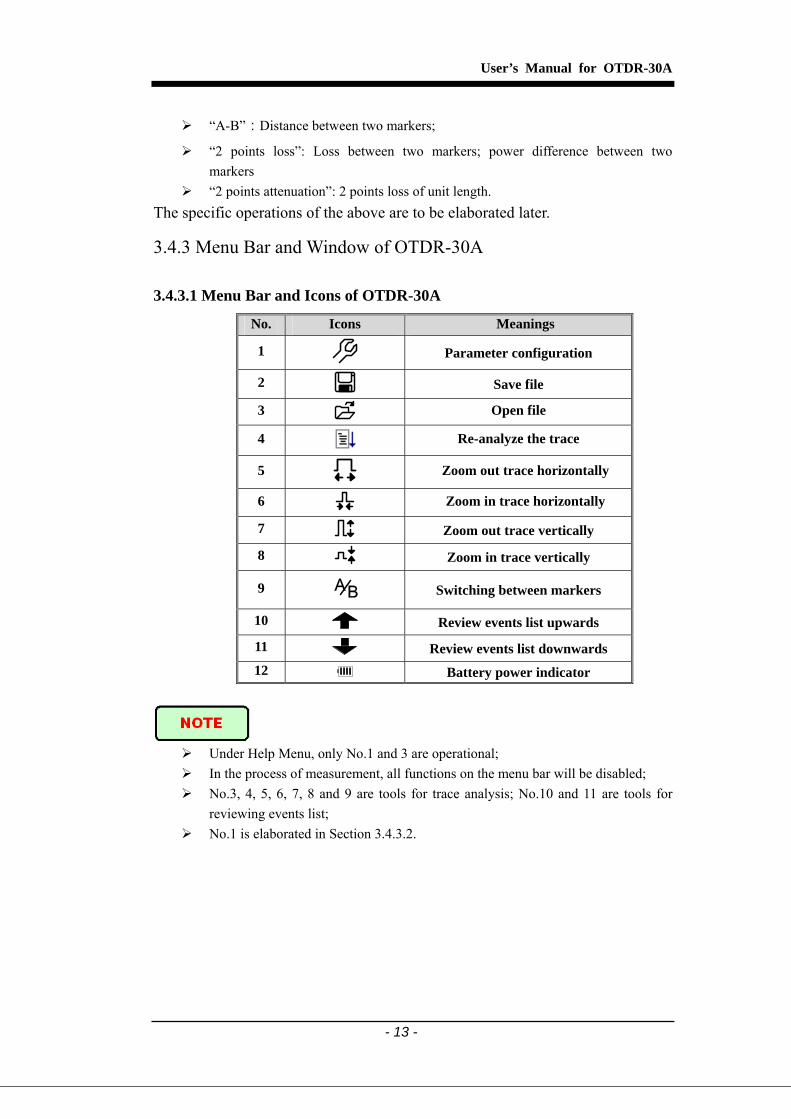
3.4.3 Menu Bar and Window of OTDR-30A 3.4.3.1 Menu Bar and Icons of OTDR-30A
No. Icons Meanings
1
Parameter configuration
2 Save file
3 Open file
4 Re-analyze the trace
5
Zoom out trace horizontally
6 Zoom in trace horizontally
7 Zoom out trace vertically
8 Zoom in trace vertically
9 BA
Switching between markers
10 Review events list upwards
11 Review events list downwards 12 Battery power indicator
Under Help Menu, only No.1 and 3 are operational; In the process of measurement, all functions on the menu bar will be disabled; No.3, 4, 5, 6, 7, 8 and 9 are tools for trace analysis; No.10 and 11 are tools for
reviewing events list; No.1 is elaborated in Section 3.4.3.2.
User’s Manual for OTDR-30A
- 14 -
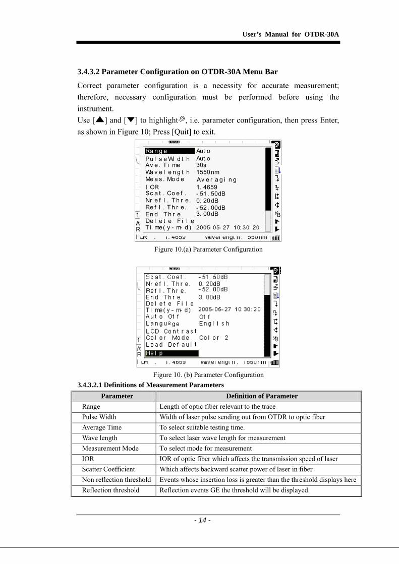
3.4.3.2 Parameter Configuration on OTDR-30A Menu Bar
Correct parameter configuration is a necessity for accurate measurement; therefore, necessary configuration must be performed before using the instrument. Use [ ] and [ ] to highlight , i.e. parameter configuration, then press Enter, as shown in Figure 10; Press [Quit] to exit.
Ave. Ti me:Range:I OR :
12Km/ Di v 3.50dB/ Div t race1.t rc 15: 20
1. 4659 1550nmWavel engt h :
BA
30s80km 2500ns
Ra n g e
Wa v e l e n g t h 1550nm
Pu l s e Wi d t h Aut oAv e. T i me 30s
I OR 1. 4659
Nr e f l . Th r e. 0. 20dBRe f l . T h r e. - 52. 00dBEn d T h r e. 3. 00dB
Sc a t . Co e f . - 51. 50dB
Av e r a g i n gMe a s . Mo d e
De l e t e F i l eT i me( y - m- d ) 2005- 05- 27 10: 30: 20
Aut o
Figure 10.(a) Parameter Configuration
Figure 10. (b) Parameter Configuration
3.4.3.2.1 Definitions of Measurement Parameters Parameter Definition of Parameter
Range Length of optic fiber relevant to the trace Pulse Width Width of laser pulse sending out from OTDR to optic fiber Average Time To select suitable testing time. Wave length To select laser wave length for measurement Measurement Mode To select mode for measurement IOR IOR of optic fiber which affects the transmission speed of laser Scatter Coefficient Which affects backward scatter power of laser in fiber Non reflection threshold Events whose insertion loss is greater than the threshold displays hereReflection threshold Reflection events GE the threshold will be displayed.

User’s Manual for OTDR-30A
- 15 -
Parameter Definition of Parameter
End threshold The first event with insertion loss GE the threshold is considered the end of fiber, and all following events will be ignored
Delete Files Delete stored trace data in the instrument Time Show current system time Auto Off On or off of Auto off function Language English LCD contrast Adjust the contrast of LCD to select Color mode setting Select suitable displaying color setting Load Default Set all parameters to factory setting Help Show help files (Quick Reference)
3.4.3.2.2 Range Configuration Generally, the range will be set according to actual length of optic fiber, so as to insure the accuracy of measurement. Under the menu of parameter configuration, use [ ] and [ ] to highlight “Range”;
Press [Enter] to enter, as shown in Figure 11; press [ ] to exit.
30s80km1. 4659
2500ns1550nm
Ave. Ti me:Range:I OR :
Pulsewidt h:Wavel engt h :
12Km/ Di v 3.50dB/ Div t race1.t rc 15: 20
Au t o1. 3km2. 5km5. 0km10km20km40km80km120km
BA
30s80km 2500ns
Ra n g e
Wa v e l e n g t h 1550nm
Pu l s e Wi d t h Aut oAv e. T i me 30s
I OR 1. 4659
Nr e f l . Th r e. 0. 20dBRe f l . Th r e. - 52. 00dBEn d Th r e. 3. 00dB
Sc a t . Co e f . - 51. 50dB
Av e r a g i n gMe a s . Mo d e
De l e t e F i l eT i me( y - m- d ) 2005- 05- 27 10: 30: 20
Aut oAu t o1. 3km2. 5km5. 0km10km20km40km80km120km
Figure 11. Set Range
Use [ ] and [ ] to select “adequate range”;Press [Enter] to confirm.
“Auto” indicates the automatic measurement function. When this function is
selected, the instrument will automatically make an intelligent selection of adequate range and pulse width for measurement. The whole process of measurement does not require any intervention of the operator.
“Auto” is the default setting.
User’s Manual for OTDR-30A
- 16 -
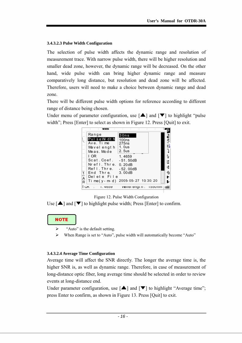
3.4.3.2.3 Pulse Width Configuration
The selection of pulse width affects the dynamic range and resolution of measurement trace. With narrow pulse width, there will be higher resolution and smaller dead zone, however, the dynamic range will be decreased. On the other hand, wide pulse width can bring higher dynamic range and measure comparatively long distance, but resolution and dead zone will be affected. Therefore, users will need to make a choice between dynamic range and dead zone. There will be different pulse width options for reference according to different range of distance being chosen. Under menu of parameter configuration, use [ ] and [ ] to highlight “pulse width”; Press [Enter] to select as shown in Figure 12. Press [Quit] to exit.
30s80km1. 4659
2500ns1550nm
Ave. Ti me:Range:I OR :
Pulsewidt h:Wavel engt h :
12Km/ Di v 3.50dB/ Div t race1.t rc 15: 20
3 0n s100ns275ns1. 0us2. 5us
BA
30s80km 2500ns
Ra n g e
Wa v e l e n g t h 1550nm
Pu l s e Wi d t h Aut oAv e. T i me 30s
I OR 1. 4659
Nr e f l . Th r e. 0. 20dBRe f l . T h r e. - 52. 00dBEn d T h r e. 3. 00dB
Sc a t . Co e f . - 51. 50dB
Av e r a g i n gMe a s . Mo d e
De l e t e F i l eT i me( y - m- d ) 2005- 05- 27 10: 30: 20
Aut o3 0n s100ns275ns1. 0us2. 5us
Figure 12. Pulse Width Configuration
Use [ ] and [ ] to highlight pulse width; Press [Enter] to confirm.
“Auto” is the default setting. When Range is set to “Auto”, pulse width will automatically become “Auto”
3.4.3.2.4 Average Time Configuration Average time will affect the SNR directly. The longer the average time is, the higher SNR is, as well as dynamic range. Therefore, in case of measurement of long-distance optic fiber, long average time should be selected in order to review events at long-distance end. Under parameter configuration, use [ ] and [ ] to highlight “Average time”; press Enter to confirm, as shown in Figure 13. Press [Quit] to exit.
User’s Manual for OTDR-30A
- 17 -
30s80km1. 4659
2500ns1550nm
Ave. Ti me:Range:I OR :
Pulsewidt h:Wavel engt h :
12Km/ Di v 3.50dB/ Div t race1.t rc 15: 20 BA
30s80km 2500ns
Ra n g e
Wa v e l e n g t h 1550 nm
Pu l s e Wi d t h Aut oAv e. T i me 30s
I OR 1. 4659
Nr e f l . Th r e. 0. 20dBRe f l . T h r e. - 52. 00dBEn d Th r e. 3. 00dB
Sc a t . Co e f . - 51. 50dB
Av e r a g i n gMe a s. Mo d e
De l e t e F i l eT i me( y - m- d) 2005- 05- 27 10: 30: 20
Aut o1 5s30s1mi n2mi n3mi n
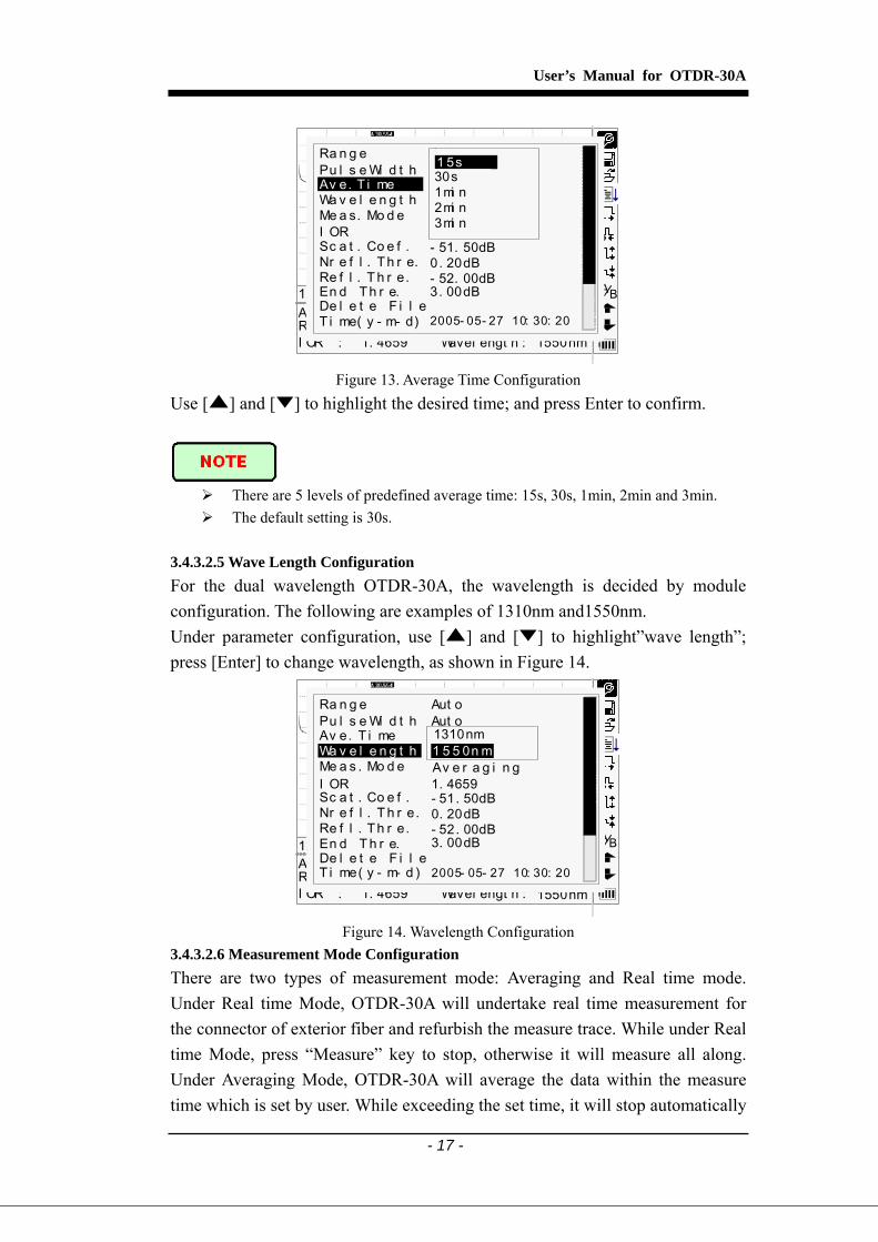
Figure 13. Average Time Configuration
Use [ ] and [ ] to highlight the desired time; and press Enter to confirm.
There are 5 levels of predefined average time: 15s, 30s, 1min, 2min and 3min. The default setting is 30s.
3.4.3.2.5 Wave Length Configuration For the dual wavelength OTDR-30A, the wavelength is decided by module configuration. The following are examples of 1310nm and1550nm. Under parameter configuration, use [ ] and [ ] to highlight”wave length”; press [Enter] to change wavelength, as shown in Figure 14.
1. 4659 1550nm
Ave. Ti me:Range:I OR : Wavel engt h :
12Km/ Di v 3.50dB/ Div t race1.t rc 15: 20 BA
30s80km 2500ns
Ra n g e
Wa v e l e n g t h 1550nm
Pu l s e Wi d t h Aut oAv e. T i me 30s
I OR 1. 4659
Nr e f l . T h r e. 0. 20dBRe f l . Th r e. - 52. 00dBEn d T h r e. 3. 00dB
Sc a t . Co e f . - 51. 50dB
Av e r a g i n gMe a s . Mo d e
De l e t e F i l eT i me( y - m- d ) 2005- 05- 27 10: 30: 20
Aut o
1 5 5 0n m1310nm
Figure 14. Wavelength Configuration
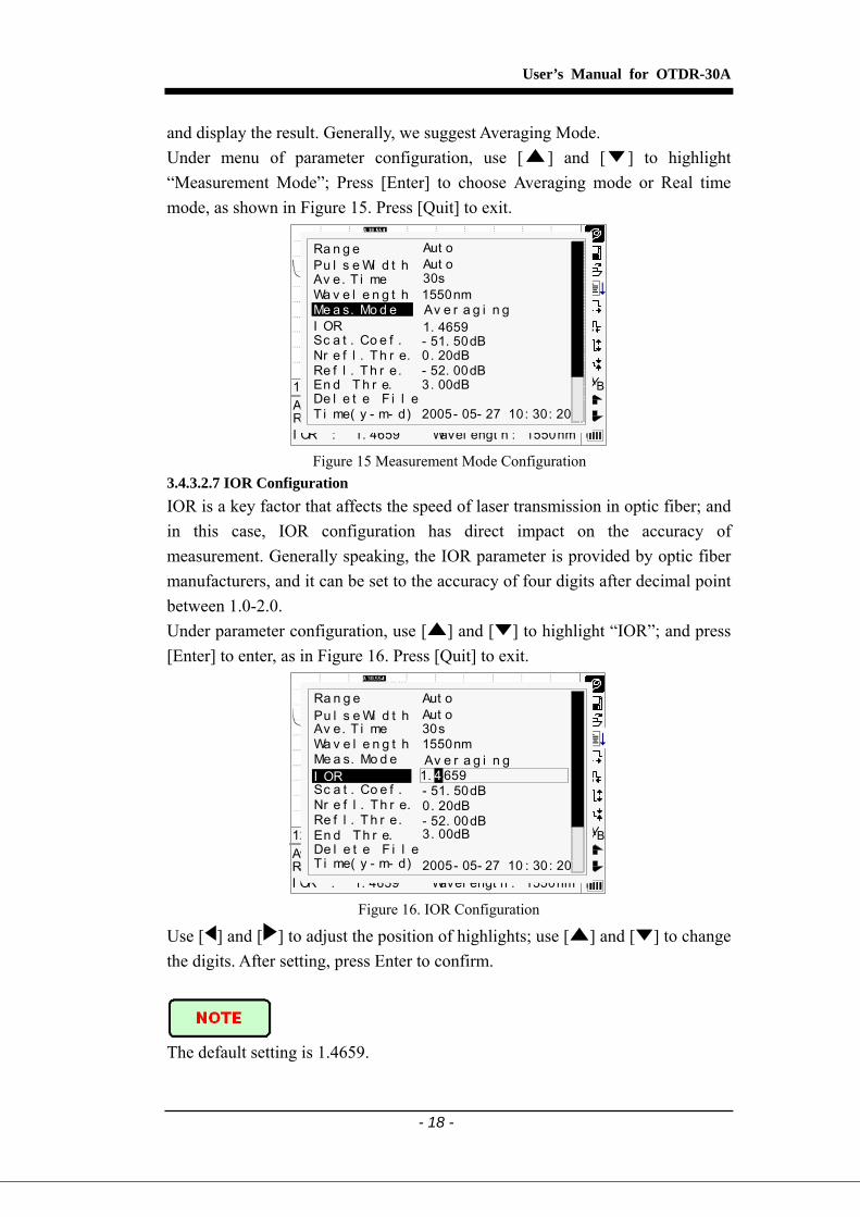
3.4.3.2.6 Measurement Mode Configuration There are two types of measurement mode: Averaging and Real time mode. Under Real time Mode, OTDR-30A will undertake real time measurement for the connector of exterior fiber and refurbish the measure trace. While under Real time Mode, press “Measure” key to stop, otherwise it will measure all along. Under Averaging Mode, OTDR-30A will average the data within the measure time which is set by user. While exceeding the set time, it will stop automatically
User’s Manual for OTDR-30A
- 18 -
and display the result. Generally, we suggest Averaging Mode. Under menu of parameter configuration, use [ ] and [ ] to highlight “Measurement Mode”; Press [Enter] to choose Averaging mode or Real time mode, as shown in Figure 15. Press [Quit] to exit.
30s80km1. 4659
2500ns1550nm
Ave. Ti me:Range:I OR :
Pulsewidt h:Wavel engt h :
12Km/ Di v 3.50dB/ Div t race1.t rc 15: 20 BA
30s80km 2500ns
Ra n g e
Wa v e l e n g t h 1550nm
Pu l s e Wi d t h Aut oAv e. T i me 30s
I OR 1. 4659
Nr e f l . Th r e. 0. 20dBRe f l . T h r e. - 52. 00dBEn d T h r e. 3. 00dB
Sc a t . Co e f . - 51. 50dB
Av e r a g i n gMe a s. Mo d e
De l e t e F i l eT i me( y - m- d) 2005- 05- 27 10: 30: 20
Aut o
Figure 15 Measurement Mode Configuration
3.4.3.2.7 IOR Configuration IOR is a key factor that affects the speed of laser transmission in optic fiber; and in this case, IOR configuration has direct impact on the accuracy of measurement. Generally speaking, the IOR parameter is provided by optic fiber manufacturers, and it can be set to the accuracy of four digits after decimal point between 1.0-2.0. Under parameter configuration, use [ ] and [ ] to highlight “IOR”; and press [Enter] to enter, as in Figure 16. Press [Quit] to exit.
1. 4659 1550nm
Ave. Ti me:Range:I OR : Wavel engt h :
12Km/ Di v 3.50dB/ Div t race1.t rc 15: 20
1. 46594
BA
30s80km 2500ns
Ra n g e
Wa v e l e n g t h 1550nm
Pu l s e Wi d t h Aut oAv e. T i me 30s
I OR
Nr e f l . Th r e. 0. 20dBRe f l . T h r e. - 52. 00dBEn d Th r e. 3. 00dB
Sc a t . Co e f . - 51. 50dB
Av e r a g i n gMe a s. Mo d e
De l e t e F i l eT i me( y - m- d) 2005- 05- 27 10 : 30: 20
Aut o
1. 46594
Figure 16. IOR Configuration
Use [ ] and [ ] to adjust the position of highlights; use [ ] and [ ] to change the digits. After setting, press Enter to confirm.
The default setting is 1.4659.

User’s Manual for OTDR-30A
- 19 -
3.4.3.2.8 Scatter Coefficient Configuration Scatter coefficient determines the value of backward scatter power. The configuration affects
the calculation of reflection value.
Under parameter configuration, use [ ] and [ ] to highlight “Scatter coefficient”; press [Enter] to enter, as shown in Figure 17. Press [Quit] to exit.
30s80km1. 4659
2500ns1550nm
Ave. Ti me:Range:I OR :
Pulsewidt h:Wavel engt h :
12Km/ Di v 3.50dB/ Div t race1.t rc 15: 20
- 51. 50dB5
BA
30s80km 2500ns
Ra n g e
Wa v e l e n g t h 1550nm
Pu l s e Wi d t h Aut oAv e. T i me 30s
I OR 1. 4659
Nr e f l . Th r e. 0. 20dBRe f l . T h r e. - 52. 00dBEn d T h r e. 3. 00dB
Sc a t . Co e f .
Av e r a g i n gMe a s . Mo d e
De l e t e F i l eT i me( y - m- d ) 2005- 05- 27 10: 30: 20
Aut o
- 51. 50dB5
Figure 17. Scatter Coefficient Configuration
Use [ ] and [ ] to adjust the position of highlights; use [ ] and [ ] to change the digits. After setting, press Enter to confirm.
The default setting is -51.50dB. 3.4.3.2.9 Non Reflection Threshold Configuration This configuration has direct impact on the listing of insertion loss events. Only events greater than this threshold will be listed. Under parameter configuration, use [ ] and [ ] to highlight “Non reflection threshold”; press [Enter] to enter, as shown in Figure 18. Press [Quit] to exit.
1. 4659 1550nm
Ave. Ti me:Range:I OR : Wavel engt h :
12Km/ Di v 3.50dB/ Div t race1.t rc 15: 20
0. 20dB0
BA
30s80km 2500ns
Ra n g e
Wa v e l e n g t h 1550nm
Pu l s e Wi d t h Aut oAv e. T i me 30s
I OR 1. 4659
Nr e f l . Th r e.Re f l . T h r e. - 52. 00dBEn d T h r e. 3. 00dB
Sc a t . Co e f . - 51. 50dB
Av e r a g i n gMe a s. Mo d e
De l e t e F i l eT i me( y - m- d) 2005- 05- 27 10: 30: 20
Aut o
0. 20dB0
Figure 18. Non Reflection Threshold
Use [ ] and [ ] to adjust the position of highlights; use [ ] and [ ] to change the digits. After setting, press Enter to confirm.

User’s Manual for OTDR-30A
- 20 -
The default setting is 0.2dB. 3.4.3.2.10 Reflection Threshold Configuration This configuration has direct impact on reflection events listing. Only reflection events are greater than this threshold will be displayed in events list. Under parameter configuration, use [ ] and [ ] to highlight “reflection threshold”; press [Enter] to enter, as shown in Figure 19. Press [Quit] to exit.
30s80km1. 4659
2500ns1550nm
Ave. Ti me:Range:I OR :
Pulsewidt h:Wavel engt h :
12Km/ Di v 3.50dB/ Div t race1.t rc 15: 20
- 52. 00dB5BA
30s80km 2500ns
Ra n g e
Wa v e l e n g t h 1550 nm
Pu l s e Wi d t h Aut oAv e. T i me 30s
I OR 1. 4659
Nr e f l . Th r e. 0. 20dBRe f l . T h r e.En d T h r e. 3. 00dB
Sc a t . Co e f . - 51. 50dB
Av e r a g i n gMe a s. Mo d e
De l e t e F i l eT i me( y - m- d) 2005- 05- 27 10: 30: 20
Aut o
- 52. 00dB5
Figure 19. Reflection Threshold Configuration
Use [ ] and [ ] to adjust the position of highlights; use [ ] and [ ] to change the digits. After setting, press Enter to confirm.
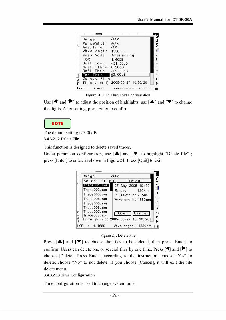
The default setting is -52.00dB. 3.4.3.2.11 End Threshold Configuration
This threshold is the end threshold of optic fiber. If the end threshold equals 3.0dB, then the first event with insertion loss greater than 3dB will be considered as the end of the optic fiber. If the value is set to 0dB, there will be no end threshold. Under parameter configuration, use [ ] and [ ] to highlight”End threshold”; press [Enter] to enter, as shown in Figure 20. Press [Quit] to exit.
User’s Manual for OTDR-30A
- 21 -
30s80km1. 4659
2500ns1550nm
Ave. Ti me:Range:I OR :
Pulsewidt h:Wavel engt h :
12Km/ Di v 3.50dB/ Div t race1.t rc 15: 20 3 . 00dB0 BA
30s80km 2500ns
Ra n g e
Wa v e l e n g t h 1550nm
Pu l s e Wi d t h Aut oAv e. T i me 30s
I OR 1. 4659
Nr e f l . Th r e. 0. 20dBRe f l . T h r e. - 52. 00dBEn d T h r e.
Sc a t . Co e f . - 51. 50dB
Av e r a g i n gMe a s . Mo d e
De l e t e F i l eT i me( y - m- d ) 2005- 05- 27 10: 30: 20
Aut o
3. 00dB0
Figure 20. End Threshold Configuration
Use [ ] and [ ] to adjust the position of highlights; use [ ] and [ ] to change the digits. After setting, press Enter to confirm.
The default setting is 3.00dB. 3.4.3.2.12 Delete File
This function is designed to delete saved traces. Under parameter configuration, use [ ] and [ ] to highlight “Delete file” ; press [Enter] to enter, as shown in Figure 21. Press [Quit] to exit.
30s80km1. 4659
2. 5us1550nm
Ave. Ti me:Range :I OR :
PulseW idt h:Wavel engt h :
12Km/ Di v 3.50dB/ Div t race1.t rc 15: 20 BA30s
80km 2500ns
Ra n g e
Wa v e l e n g t h 1550nm
Pu l s e Wi d t h Aut oAv e. T i me 30s
I OR 1. 4659
Nr e f l . Th r e. 0. 20dBRe f l . T h r e. - 52. 00dBEn d T h r e. 3. 00dB
Sc a t . Co e f . - 51. 50dB
Av e r a g i n gMe a s . Mo d e
De l e t e F i l eT i me( y - m- d ) 2005- 05- 27 10 : 30: 20
Aut oSe l e c t f i l e: 0 1 1 8/ 3 0 0Tr ace001. sorTr ace002. sorTr ace003. sorTr ace004. sorTr ace005. sor
Ca n c e lOp e nTr ace006. sorTr ace007. sorTr ace008. sor
27- May - 2005 10 : 30Range : 120kmPul seWi dt h : 2 . 5usWavel engt h : 1550nm
Figure 21. Delete File
Press [ ] and [ ] to choose the files to be deleted, then press [Enter] to confirm. Users can delete one or several files by one time. Press [ ] and [ ] to choose [Delete]. Press Enter], according to the instruction, choose “Yes” to delete; choose “No” to not delete. If you choose [Cancel], it will exit the file delete menu. 3.4.3.2.13 Time Configuration
Time configuration is used to change system time.
User’s Manual for OTDR-30A
- 22 -
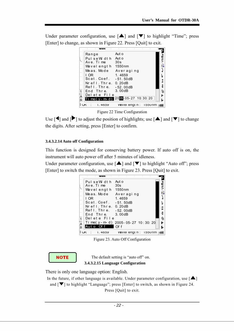
Under parameter configuration, use [ ] and [ ] to highlight “Time”; press [Enter] to change, as shown in Figure 22. Press [Quit] to exit.
30s80km1. 4659
2500ns1550nm
Ave. Ti me:Range:I OR :
Pulsewidt h:Wavel engt h :
12Km/ Di v 3.50dB/ Div t race1.t rc 15: 20
20 - 12- 10 10: 30: 2003
BA
30s80km 2500ns
Ra n g e
Wa v e l e n g t h 1550nm
Pu l s e Wi d t h Aut oAv e. T i me 30s
I OR 1. 4659
Nr e f l . Th r e. 0. 20dBRe f l . T h r e. - 52. 00dBEn d T h r e. 3. 00dB
Sc a t . Co e f . - 51. 50dB
Av e r a g i n gMe a s . Mo d e
De l e t e F i l eT i me( y - m- d )
Aut o
20 - 05- 27 10: 30: 2005
Figure 22 Time Configuration
Use [ ] and [ ] to adjust the position of highlights; use [ ] and [ ] to change the digits. After setting, press [Enter] to confirm.
3.4.3.2.14 Auto off Configuration
This function is designed for conserving battery power. If auto off is on, the instrument will auto power off after 5 minutes of idleness. Under parameter configuration, use [ ] and [ ] to highlight “Auto off”; press [Enter] to switch the mode, as shown in Figure 23. Press [Quit] to exit.
1. 4659 1550nm
Ave. Ti me:Range:I OR : Wavel engt h :
12Km/ Di v 3.50dB/ Div t race1.t rc 15: 20 BA
2500ns
Wa v e l e n g t h 1550nm
Pu l s e Wi d t h Aut oAv e. T i me 30s
I OR 1. 4659
Nr e f l . Th r e. 0. 20dBRe f l . T h r e. - 52. 00dBEn d T h r e. 3. 00dB
Sc a t . Co e f . - 51. 50dB
Av e r a g i n gMe a s. Mo d e
De l e t e F i l eT i me( y - m- d ) 2005- 05- 27 10 : 30: 20Au t o Of f Of f
Figure 23. Auto Off Configuration
The default setting is “auto off” on. 3.4.3.2.15 Language Configuration
There is only one language option: English. In the future, if other language is available. Under parameter configuration, use [ ]
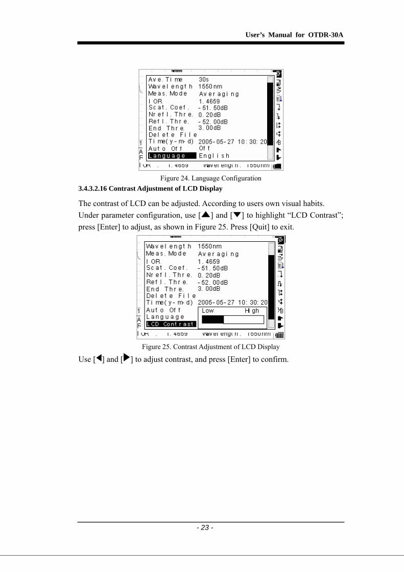
and [ ] to highlight “Language”; press [Enter] to switch, as shown in Figure 24. Press [Quit] to exit.
User’s Manual for OTDR-30A
- 23 -
Figure 24. Language Configuration
3.4.3.2.16 Contrast Adjustment of LCD Display
The contrast of LCD can be adjusted. According to users own visual habits. Under parameter configuration, use [ ] and [ ] to highlight “LCD Contrast”; press [Enter] to adjust, as shown in Figure 25. Press [Quit] to exit.
Figure 25. Contrast Adjustment of LCD Display
Use [ ] and [ ] to adjust contrast, and press [Enter] to confirm.

User’s Manual for OTDR-30A
- 24 -
3.4.3.2.17 Color Mode Setting Choose the different displaying color scheme according to the user’s fancy.
Under parameter configuration, use [ ] and [ ] to highlight “Auto “Color mode”, press [Enter] to choose different mode. Press [Quit] to exit, as in Figure 26.
Figure26. Color Mode Setting
Use [ ] and [ ] to highlight suitable color mode setting; press [Enter] to confirm the selection.
3.4.3.2.18 Defaults Set
This function is used to set OTDR parameters to factory settings. Those
parameters include:range, pulse width, average time, IOR, non reflection
threshold, reflection threshold, end threshold, and scatter coefficient. Under parameter configuration, use [ ] and [ ] to highlight “Load defaults”; press [Enter] to enter, as shown in Figure 27. Press [Quit] to exit.
Figure 27. Load Defaults
Use [ ] and [ ] to highlight “yes” or “no”; press [Enter] to confirm.

User’s Manual for OTDR-30A
- 25 -
3.4.3.2.19 Help Users can get the quick reference via [Help] menu. Under parameter configuration, Use [ ] and [ ] to highlight “Help”; Press
[Enter] to enter, as shown in 28.(a)、(b)、(c). Press [Quit] to exit.
Figure 28. (a) Help
Figure 28. (b) Help
Figure 28. © Help
User’s Manual for OTDR-30A
- 26 -
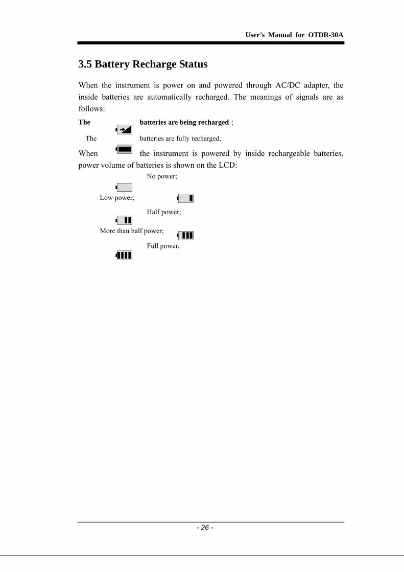
3.5 Battery Recharge Status
When the instrument is power on and powered through AC/DC adapter, the inside batteries are automatically recharged. The meanings of signals are as follows: The batteries are being recharged;
The batteries are fully recharged.
When the instrument is powered by inside rechargeable batteries, power volume of batteries is shown on the LCD:
No power;
Low power;
Half power;
More than half power;
Full power.

User’s Manual for OTDR-30A
- 27 -
4. Trace Measurement and Processing of Existing
Traces
4.1 Instructions on GUI
After power on, power on interface displays on the LCD, as shown in Figure 29:
Figure 29. Power on Interface
Three seconds after power on, the interface will be automatically directed to quick reference:
1. Connect f i ber t o opt i cal por t2 . Pr ess ‘ Run/ St op’ t o st ar t . . .
Av oi d Ey es Ex pos ed t o Las er !
BA
- - s- - km- . - - - -
- - - us- - - - nm
Ave. Ti me:Range:I OR :
Pul sewi dt h :Wavel engt h :
- - Km/ Di v - - dB/ Di v Par a- 1
3. or t o br owse event t abl e t o vi ew t r ace par amet er s
Figure 30. Quick Reference

User’s Manual for OTDR-30A
- 28 -
4.2 Trace Measurement of OTDR-30A
One complete trace can be obtained for each measurement. Also, OTDR-30A can load a saved trace.
Before each measurement, if the operator is not familiar with the cautions, please do follow instructions in this manual for personal safety.
Make sure that the optical fiber or cable is not in use and there is no laser beam in the fiber before testing via OTDR-30A. Otherwise, it may result in imprecise test trace, even permanent damage for the OTDR-30A.
4.2.1 Trace Measurement- Connect Optical Fiber
Connect optic fiber to OTDR-30A optic output directly, no tools needed. Clean connectors, for details please refer to chapter A; Clean tie-ins and check whether they are FC/PC tie-ins or not; Connect optic fiber to the instrument.
4.2.2 Trace Measurement - Parameter Configuration
For details relating to parameter configuration, please refer to 3.4.3.2, Parameter Configuration on OTDR-30A Menu Bar. If the parameters are unclear, please use the default parameters of the instrument, however, this may cause an increase of measurements errors.
Range is set to “Auto”, when auto measurement is on.
4.2.3 Trace Measurement- Auto
Auto measurement can be applied in case that the length of optic fiber is unidentifiable. OTDR-30A auto select adequate range for measurement. Steps for Auto measurement:
Parameter configuration: for detailed operations,please refer to 3.4.3.2,Parameter
Configuration on OTDR-30A Menu Bar. Set range to ”AUTO”;
Measure: press [ ] to start measurement, and the interface is as in Figure 31. (a), (b).

User’s Manual for OTDR-30A
- 29 -
00: 3000: 16
Ave. Ti me :Ti me Passed :
BA
Figure 31.(a) Measuring
00:3000:30
Anal yzi ng …Ave . T ime :T ime Passed :
BA
Figure 31.(b) Measuring
Interface: “Total: 00:30” ------------ Measure time which is set by user is 30 seconds;
“Passed: 00:16” ------------ Total measurement time has passed 16 seconds;
“ “ ----------- Flickering of this sign means laser is active
When measurement is in progress, all keys are disabled except [On/Off], and
[ ] . After a certain period of time, the trace displays on the GUI. The trace in the
Figure below is a trace during measurement, which will be refreshed for every certain period of time to demonstrate the whole process to users in real time. But at the end of measurement, the trace will be final, as shown in Figure 32.

User’s Manual for OTDR-30A
- 30 -
BA
30s80km1. 4659
2. 5us1550nm
Ave. Ti me:Range:I OR :
Pul sewi dt h :Wavel engt h :
12Km/ Di v 3. 50dB/ Di v t r ace 1 Par a- 1
Figure 32. Trace Measurement of OTDR-30A
4.2.4 Trace Measurement - Manual
If the operators have full knowledge of measured optic fiber, they can set accurate parameters, and achieve optimal measurement results.
Change “range”: Refer to 3.4.3.2.2 range configuration to select adequate range.
Measure:Press [ ] to start measurement. The process is the same with Auto
measurement.
4.2.5 Trace Measurement -Reasons of Measurement Failures
If measurement failures occur, reasons may be one of the following: Events may be too close to each other.
Shorten the pulse width, and make another try. If failure still occurs, please try to measure from the other end of the optic fiber;
Low SNR Try to use wider pulse or increase average time, and try again;
Incorrect parameter configuration Check parameter configuration, and try again.
4.3 Information Window
Items of information window: measurement parameters, analysis parameters, and information regarding marker A/B. For details regarding the information window, please refer to 3.4.2 OTDR-30A information window.
4.3.1 Switch between Information Window Items
Under GUI of Figure 32, press [Quit] and the items of information window will
User’s Manual for OTDR-30A
- 31 -
display in a rotating fashion: measurement parameter→ analysis information→ Event list→ information of marker A/B → measurement parameter.
4.3.2 Review Event List
Under GUI of Figure 32, press [Quit], items in information window will switch to event list information.
Use [ ] and [ ] too highlight or , then press [Enter] to review events
list, will browse upwards and downwards.
4.3.3 Review Marker A/B Information
4.3.3.1 Switching between Marker A/B
Under GUI of Figure 32, use [ ] and [ ] to highlight BA , then press [Enter] to switch between marker A/B. Use [ ] and [ ] to move marker A or B.
4.3.3.2 Information between Marker A/B
Under GUI of Figure 32, press [Quit] switch information window to marker A/B. Press[ ]or[ ] to change the position of marker A or B, and information of marker A/B will change accordingly in the information window.
User’s Manual for OTDR-30A
- 32 -
4.4 Zoom out Trace Horizontally
This function is designed for users to review details of every event more carefully.
Under GUI of Figure 32, use [ ] and [ ] to highlight ,then press [Enter] to zoom out trace horizontally.
Press [ ] or [ ] to move marker to the event point to be observed; To examine information of event point, please according to “4.3.3.1” Switching
between Marker A/B”
4.5 Zoom in Trace Horizontally
This function is to zoom in trace horizontally.
Under GUI of Figure 32, use [ ] and [ ] to highlight , and press [Enter] to zoom in trace.
4.6 Zoom out Trace Vertically
This function is designed for users to review event points more carefully.
Under GUI of 32, press [ ] and [ ] to highlight , then press [Enter] to zoom out vertically;
Use [ ] and [ ] to mover marker to event point to be observed; For details, please refer to 6.3.3.1 switching between Marker A/B.
4.7 Zoom in Trace Vertically
This function is designed to zoom in trace vertically.
Under GUI of Figure 31, press [ ] and [ ] to highlight , then press [Enter] to zoom in trace vertically.

User’s Manual for OTDR-30A
- 33 -
4.8 Save Trace
When auto or manual measurement is finished, the measurement trace can be saved. Contents of trace saved include: Trace curve and related information of trace.
Under GUI of Figure 32, use [ ] and [ ] to highlight , then press [Enter] to enter, as shown in Figure 33.
30s80km1. 4659
2. 5us1550nm
Ave. Ti me:Range:I OR :
Pul seWi dt h :Wavel engt h :
12Km/ Di v 3.50dB/ Div t race1.t rc Par a- 1Ca n c e l
ABCDEFGHI JKLMNOPQRSTUVWXYZ 1234567890 _
Sp a c e Us e d: 1 1 8/ 1 0 0
OK De l e t e
RACE0T
T
BA
Figure 33. Save Trace
Input filename: use [ ],[ ],[ ] and [ ] to choose the alphabet or Arabic numerals one by one, and press [Enter] to confirm. The length of filename will not exceed 8 characters of alphabet or Arabic numerals.
Save file: use [ ],[ ],[ ] and [ ] to highlight “OK”, press [Enter] to save;
Cancel saving file: use[ ],[ ],[ ] and [ ] to highlight “cancel”, press [Enter] to cancel the operation of “save file”;
Delete alphabet/Arabic numerals: use [ ],[ ],[ ] and [ ] to highlight
“Delete”, press [Enter] to delete the alphabet/Arabic numerals;
Memory space: 118/300 means that total memory space is 300 files; it has already saved 118 files so far.
4.9 Browse Saved Traces
Under GUI of Figure 32 or Figure 28., use [ ] and [ ] to highlight , press [Enter] to confirm, as shown in Figure 34.

User’s Manual for OTDR-30A
- 34 -
30s80km1. 4659
2. 5us1550nm
Ave. Ti me:Range :I OR :
PulseW idt h:Wavel engt h :
12Km/ Di v 3.50dB/ Div t race1.t rc 15: 20 BA30s
80km 2500ns
Ra n g e
Wa v e l e n g t h 1550nm
Pu l s e Wi d t h Aut oAv e. T i me 30s
I OR 1. 4659
Nr e f l . Th r e. 0. 20dBRe f l . T h r e. - 52. 00dBEn d T h r e. 3. 00dB
Sc a t . Co e f . - 51. 50dB
Av e r a g i n gMe a s . Mo d e
De l e t e F i l eT i me( y - m- d ) 2005- 05- 27 10 : 30: 20
Aut oSe l e c t f i l e: 1 1 8/ 3 0 0Tr ace001. sorTr ace002. sorTr ace003. sorTr ace004. sorTr ace005. sor
Ca n c e lOp e nTr ace006. sorTr ace007. sorTr ace008. sor
27- May - 2005 10 : 30Range : 120kmPul seWi dt h : 2 . 5usWavel engt h : 1550nm
Figure 34. Browse Saved Traces
Use [ ] and [ ] to highlight the certain trace, then use [ ] and [ ] to choose [Open] or [Cancel]; Press [Enter] to confirm.
Memory space: 118/300 means that total memory space is 300 files; it has already saved 118 files so far.
4.10 Upload Saved Traces
Saved traces can be uploaded to PC through the associated software of trace manager, with which traces can be further processed on PC.
Install the software, and run; Power off OTDR-30A;
Connect OTDR-30A to PC through RS232(or USB)interface cable;
Power on OTDR-30A, and upload data with the software. The example process is in Figure 35.
30s80km1. 4659
2. 5us1550nm
Ave. Ti me:Range:I OR :
Pul seWi dt h :Wavel engt h :
12Km/ Di v 3. 50dB/ Di v t r ace1 Par a- 1
Upl oad f i l esPl ease wai t ! ( 4/ 8)
BA
Figure 35. Upload Saved Traces
User’s Manual for OTDR-30A
- 35 -
Make sure the instrument is powered off when connecting to PC through RS232
(or USB) data cable; Make sure the cable is secure, then power on. USB supports hot plug. However USB operation rules must be obeyed while
connecting to PC. To install USB driver correctly is necessary before uploading any data; Make sure USB is disconnected properly, otherwise there may be data loss.
This operation cannot be applied under GUI of parameter configuration, save trace, browse saved traces, or measuring in progress.

User’s Manual for OTDR-30A
- 36 -
A. Maintenance and Calibration
Maintenance of Batteries
The battery for this instrument is a rechargeable NiMH battery. All the NiMH batteries have been correctly installed and gone thorough precise debugging. Please do not open the instrument to replace batteries.
Notes for maintenance of batteries in the instrument:
In order for the OTDR-30A (including the batteries) to meet specifications, the storage temperature should be within 15oC to 30 oC. And the instruments should be stored in low humidity environments.
One rechargeable NiMH battery is inside the instrument. Do not replace the battery by yourself.
If the instrument is left unused for a long time (idle for over 2 months), it is recommended to recharge the battery every other month.
Do not charge the battery for too long (more than 8 hours). Otherwise permanent damage could result to the battery.
Cleaning of Interfaces
Interfaces must be kept clean. Special alcohol may be used to clean optic output. Always replace protective dust caps when the unit is not being used, and keep the protective dust caps clean. In addition, flanges must be kept clean periodically,
Effects of Cleaning Interfaces and Connectors
The diameter of optic core is 9um, and diameter of dust and other particulates ranges from 1/100 to 1/10 um. Comparatively speaking, the size of dust and other particulates can cover part of optic end and therefore degrade the performance of the instrument. In addition, power density may burn dust into optic fiber and induce further damage (for example, 0dBm optic power may produce about 16000000W/m*m power density in single mode fiber). In this case, measurement will be inaccurate and irreversible.
User’s Manual for OTDR-30A
- 37 -
Safety instructions to be followed before cleaning
a) Make sure the instrument is power off when cleaning; b) Any operations contrary to the instructions may result in dangerous laser
injuries; c) Make sure laser source is off, when cleaning any optic connectors; d) When the instrument is in operation, please always avoid looking directly
into optic output. Although laser radiation is invisible, it may do serious injury to eyesight;
e) Be cautious of electric shock and make sure AC power is disconnected from the instrument before cleaning. Always use dry or moist soft cloth to clean the outside of the instrument, and never clean the inside;
f) Please do not add any accessory to optic instrument or adjust the instrument arbitrarily;
g) For maintenance, always go to qualified or certified professionals.
Tools for Cleaning Interfaces and Connectors a) Optic fiber cleaner (for cleaning of optic connectors) b) Optic fiber cleaning rod (for cleaning of optic outputs) c) Optic fiber cleaning tissue (for cleaning optic interfaces) d) Isopropyl alcohol e) Cotton ball f) Paper tissue g) Cleaning brush h) Compressed
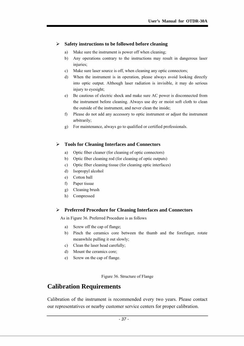
Preferred Procedure for Cleaning Interfaces and Connectors As in Figure 36. Preferred Procedure is as follows
a) Screw off the cap of flange; b) Pinch the ceramics core between the thumb and the forefinger, rotate
meanwhile pulling it out slowly; c) Clean the laser head carefully; d) Mount the ceramics core; e) Screw on the cap of flange.
Figure 36. Structure of Flange
Calibration Requirements
Calibration of the instrument is recommended every two years. Please contact our representatives or nearby customer service centers for proper calibration.

User’s Manual for OTDR-30A
- 38 -
B. Specifications
Optical Specifications OTDR-30A
Dynamic Range (dB)(1) 24/24
Wavelength (nm) 1310/1550 ± 20 Fiber Type Single mode Selectable Ranges (km) 1.3/2.5/5/10/20/40/80/120
Pulse Widths 12ns/30ns/100ns/275ns/1us/2.5us
Average Time 15s/30s/1min/2min/3min
Attenuation Dead Zone(2) 25 m
Event Dead Zone(2) 10 m
Sampling Range 1m~10m
Sampling Points 16000 Points (Maximum)
Distance Measure Accuracy ±(1 m + 5×10⁻⁵×Distance (m)+ sampling space)
Attenuation Measure Accuracy 0.05dB/dB
Reflection Measure Accuracy ±4dB
Measurement Data Storage 300 test curves
Connector Type FC/PC
Data Transmission RS-232/USB port Note: (1) The dynamic range is measured at maximum pulse width within average time of 3
minutes; (2) Conditions for blind Measurement: Reflection events are within a range of 4km;
reflection intensity is less than -35dB; and the blind zone is measured at the minimum pulse width.
Other Parameters Power Supply NiMH rechargeable battery/AC adapter, auto recharging
Battery Capacity Support over 3.8 hours operating on one charge or >20 hours standby
Operating Temperature -10℃ to 50℃
Storage Temperature -20℃ to 60℃
Relative Humidity 10 to 90% (non-condensing)
Weight 0.87kg
Dimensions (H x W x T) 7.7×3.9×2.4 inch (196×100×60mm)
C. Warranty Information
Terms of Warranty
All CTC Union products are warranted against defective material and workmanship for a period of one (1) year from the date of shipment to the original customer. Any product found to be defective within the warranty period would be repaired or replaced by CTC Union free of charge. In no case will CTC Union liabilities exceed the original purchase price of the product.
Exclusions
The warranty on your equipment shall not apply to defects resulting from the following:
Unauthorized repair or modification Misuse, negligence, or accident
CTC Union reserves the right to make changes to any of its products at any time without having to replace or change previously purchased units.
Returning Instruments
To return instrument for reasons of yearly calibration or other, please contact the local Customer Service Center of CTC Union to obtain additional information and a RMA# (Return Materials Authorization number). And describe briefly reasons for the return of the equipment, to allow us offer you more efficient service.

To return the instrument in the case of repair, calibration or other maintenance, please note the following:
Be sure to pack the instrument with soft cushion like Polyethylene, so as to protect the shell of the instrument.
Please use the original hard packing box if possible. If using other packing material, please ensure at least 3 cm soft material around the instrument.
Be sure to seal the packing box with packing tape. Be sure to ship to your representative or the agent of CTC Union in a reliable way.
Contacting Customer Service
Please check our web site (www.ctcu.com) for updates to this manual and additional application information. If you need technical or sales support, please contact local CTC Union Technologies Customer Service.
Fiber Tester Series CTC Union Technologies Co., Ltd.
Far Eastern Vienna Technologies Center (Neihu Technology Park)
8F, No. 60, Zhouzi St., Neihu, Taipei, Taiwan Phone:(886) 2.2659.1021 Fax:(886) 2.2.799.1355
E-mail:[email protected]
http://www.ctcu.com


