Wide range of bio-inspired configurationsVarious concepts and performances
Importance of vortex wake structure – Wing wake interactionReynolds Number – Added mass – Inertial forces
RoboBeeHarvard 20113cm - 80mg
SmartBirdFesto 20112m – 450g
Nano-HummingbirdAerovironment 2011
16cm – 19g
DelFly MicroTUDelft 2008
10cm – 3g
Flapping wing Unmanned Aerial Vehicles
Several aeromechanic architectures Flapping actuator
• dc motor + crank-rocker mechanism• vibrating piezoelectric lamella
Control• wing-stroke frequency (crank-rocker)• wing-stroke amplitude (vibrating lamella)• control surfaces• wing shape deformation• wing-stroke shape
lift
torques
log Re543
JSO
Aer
ial R
obot
ics
Oct
. 20
14
4
Flapping wings at ONERA
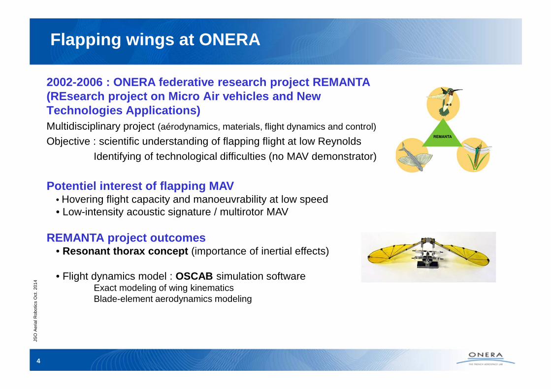
2002-2006 : ONERA federative research project REMAN TA (REsearch project on Micro Air vehicles and New Technologies Applications)Multidisciplinary project (aérodynamics, materials, flight dynamics and control)
Objective : scientific understanding of flapping flight at low ReynoldsIdentifying of technological difficulties (no MAV demonstrator)
Potentiel interest of flapping MAV • Hovering flight capacity and manoeuvrability at low speed• Low-intensity acoustic signature / multirotor MAV
REMANTA project outcomes• Resonant thorax concept (importance of inertial effects)
• Flight dynamics model : OSCAB simulation softwareExact modeling of wing kinematicsBlade-element aerodynamics modeling
JSO
Aer
ial R
obot
ics
Oct
. 20
14
5
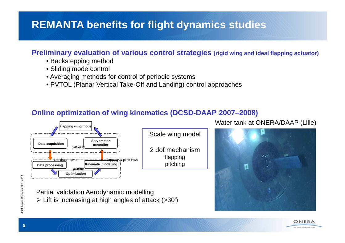
Preliminary evaluation of various control strategie s (rigid wing and ideal flapping actuator)• Backstepping method• Sliding mode control• Averaging methods for control of periodic systems• PVTOL (Planar Vertical Take-Off and Landing) control approaches
Online optimization of wing kinematics (DCSD-DAAP 20 07–2008)
Flapping wing model
Kinematic modelling
Optimization
Data acquisitionServomotorcontroller
flapping & pitch laws
Data processing
Lift, drag, power
(LabView)
(Matlab)
Scale wing model
2 dof mechanismflapping pitching
Water tank at ONERA/DAAP (Lille)
REMANTA benefits for flight dynamics studies
Partial validation Aerodynamic modelling� Lift is increasing at high angles of attack (>30°)
JSO
Aer
ial R
obot
ics
Oct
. 20
14
6
In-Art ANR Project (2009-2013)
ObjectiveDesign of a bio-inspired Nano-Air-VehicleIEMN, LPPI, ONERA/DAAP"Aeroelastic framework of insect-like flapping-wing applied to the design of a resonant nano air vehicle"
Concept• Actuation on an active bending and passive torsion• No articulations – rigid thorax• Wing mode-shape designed to reproduce
insect wing kinematics• SU-8 Manufacturing
wingspan : 3cmweight : 30mg
JSO
Aer
ial R
obot
ics
Oct
. 20
14
7
Proposed concept in REMANTA project (2002)• flapping in horizontal stroke plane• lift, propulsion and stabilization driven by wing stroke control • wingspan 15-20cm• flexible wings• wing stroke frequency ~30Hz• weight ~ 20g
Technological locks• design and realization of flapping mechanismcapable of controlling several DoF• design and realization of flexible wingswith adequate wing profile
ONERA/DCSD Flapping wing studies
Nano Hummingbird characteristics
Wing motion & lift in hovering flight
JSO
Aer
ial R
obot
ics
Oct
. 20
14
8
Flapping wing system
• Resonant mechanism (minimum losses)
• Direct control of 3 DoF (lift, pitch, roll) by adjustement of wing stroke amplitude and middle position
Tools development for wing structure designing and dimensioningSimulation of wing deformation using Absolute Nodal Coordinates Formulation (ANCF) method
Finite element modeling for large displacements (applied to flexible multibody dynamics)
Design of an onboard flapping mechanism • Resonant mechanism
ONERA patent pending
• Use of micro electrical motors(coreless et brushless motors)
• Design of specific motor controllers
Experimental performances75mm wing
frequency 28Hzamplitude +/- 70°
100mm wingfrequency 23Hzamplitude +/- 60°
JSO
Aer
ial R
obot
ics
Oct
. 20
14
10
Guided parafoil air delivery systems
JSO
Aer
ial R
obot
ics
Oct
. 20
14
11
Guided parafoil air delivery systems
General objectiveEnhancement of all weather operational performance (wrt. existing US systems)DGA-TA research focus :
FAWOPADS (Future All Weather Operations Payload Aerial Delivery Systems)
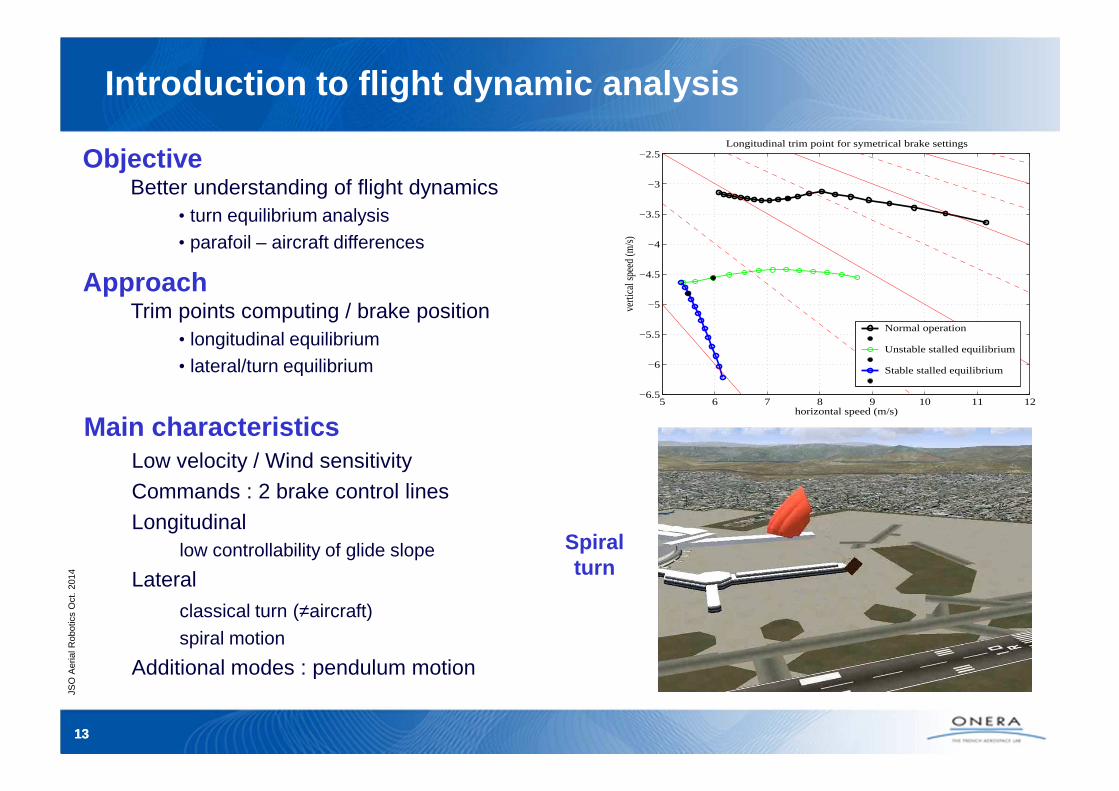
� Improving knowledge of parafoil flight dynamics � Analysis of factors influencing landing accuracy
Development of a network of expertise (DGA-TA, ISAE, ONERA, …)
DGA-TA contracts (2010-2011 & 2013-2015) • Development of flight dynamics modeling and analysis tools• Parameter estimation of parafoil modeling from flight test data• Development of a new guidance strategies
ONERA/DCSD experimental activityImproving our experimental knowledge with a mini powered paragliderMini powered paraglider : OPALE ParamodelsCanopy : SPIRAL 2,4m²Payload : 2-3kg
No technological locksOff-the-shelf components : sensors, actuators, controller, …
JSO
Aer
ial R
obot
ics
Oct
. 20
14
1212
Development of parafoil modeling
Constitutive elements• Mechanical modeling
relative motions of payload wrt canopy � from 6 DOF (no relative motion) to 9 DOF (3 rotations)
• Aerodynamic modelingaerodynamic coefficients relative to canopy
Well documented for longitudinal coefficientsPoorly documented for lateral coefficients
Canopy unsteady aerodynamics : added mass and inertia
Model implementation in Matlab• Matlab / Simulink simulation
Selection et evaluation of an advanced off-the-shel f controllerPIXHAWK (ETH Zurich)Open-source, open-hardware project 2 processors
PX4 FMU Cortex M4 – 168MHz – FPUPX4 IO Cortex M3
RTOS : NuttXµObject Request BrokerDrivers – µSD Data logging
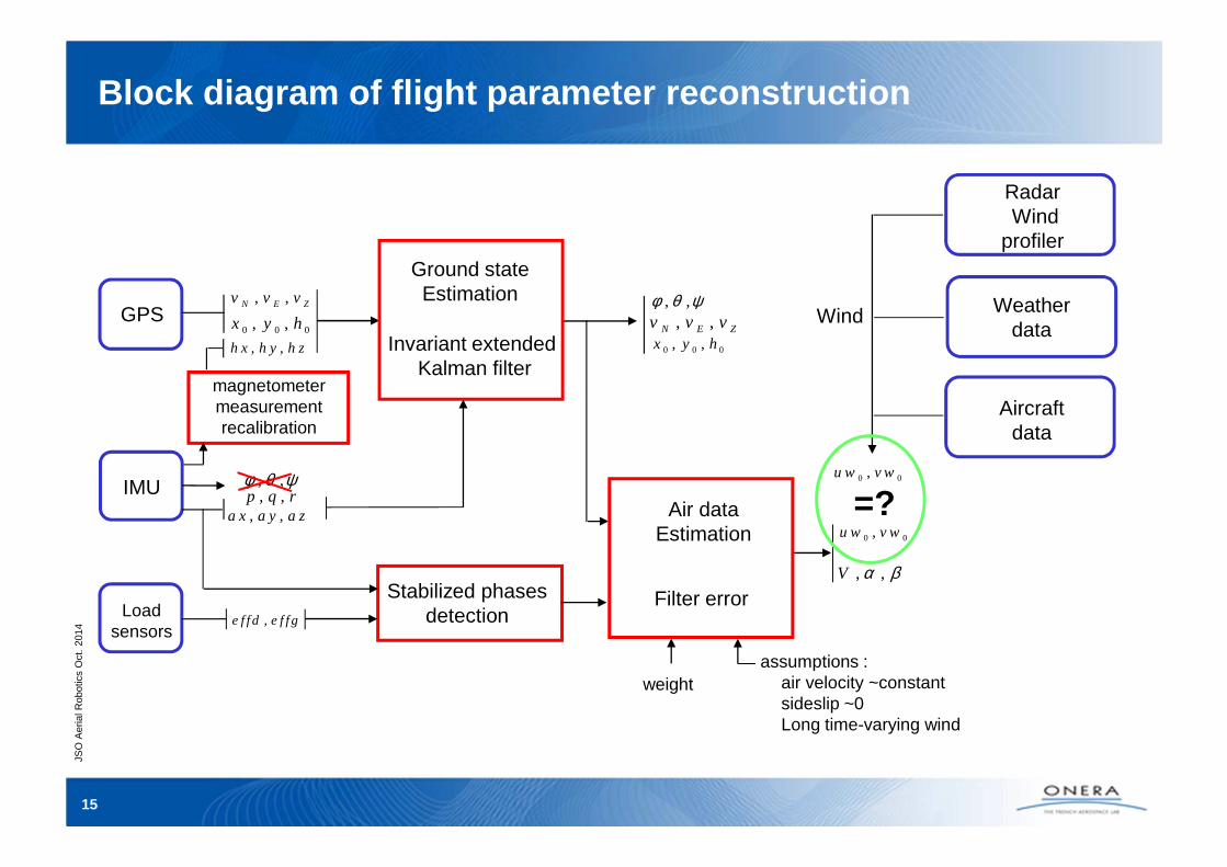
Mini powered paraglider projectDesign of a real time ground state estimator
Groung state estimationFirst component for the design of an automatic landing systemInvariant extended Kalman Filter (15 states)3 correction modes
• alignment (inertial)• navigation without GPS (inertial + magnetometer)• data fusion with GPS (inertial + magnetometer + GPS)
C++ programmingMatrix library (symmetric matrices)Estimation and logging at 100Hz
IMU(100Hz)
GPSHemisphere
(10Hz)
anemometer
R/C Sbusreceiver
PIXHAWK
JSO
Aer
ial R
obot
ics
Oct
. 20
14
17
� Parameter estimation of parafoil modeling
� Development of a new adaptive guidance strategy to ensureaccurate delivery providing good wind resistance
Efficient use of parafoil flight dynamics capabilities
� First experiments of flight control laws on the ONERAmini-powered paraglider
On-going DGA-TA activities
JSO
Aer
ial R
obot
ics
Oct
. 20
14
18
Wing demonstrator with innovative control surfaces
DEVIS
JSO
Aer
ial R
obot
ics
Oct
. 20
14
19
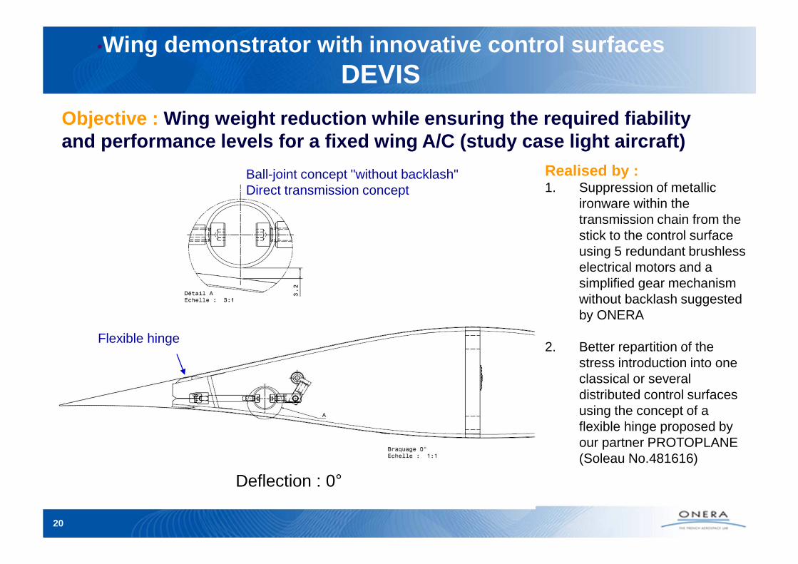
•Wing demonstrator with innovative control surfaces DEVIS
Objective : Wing weight reduction while ensuring the required f iability and performance levels for a fixed wing A/C (study case light aircraft)
Realised by :1. Suppression of metallic
ironware within the transmission chain from the stick to the control surface using 5 redundant brushless electrical motors and a simplified gear mechanism without backlash suggested by ONERA
2. Better repartition of the stress introduction into one classical or several distributed control surfaces using the concept of a flexible hinge proposed by our partner PROTOPLANE (Soleau No.481616)
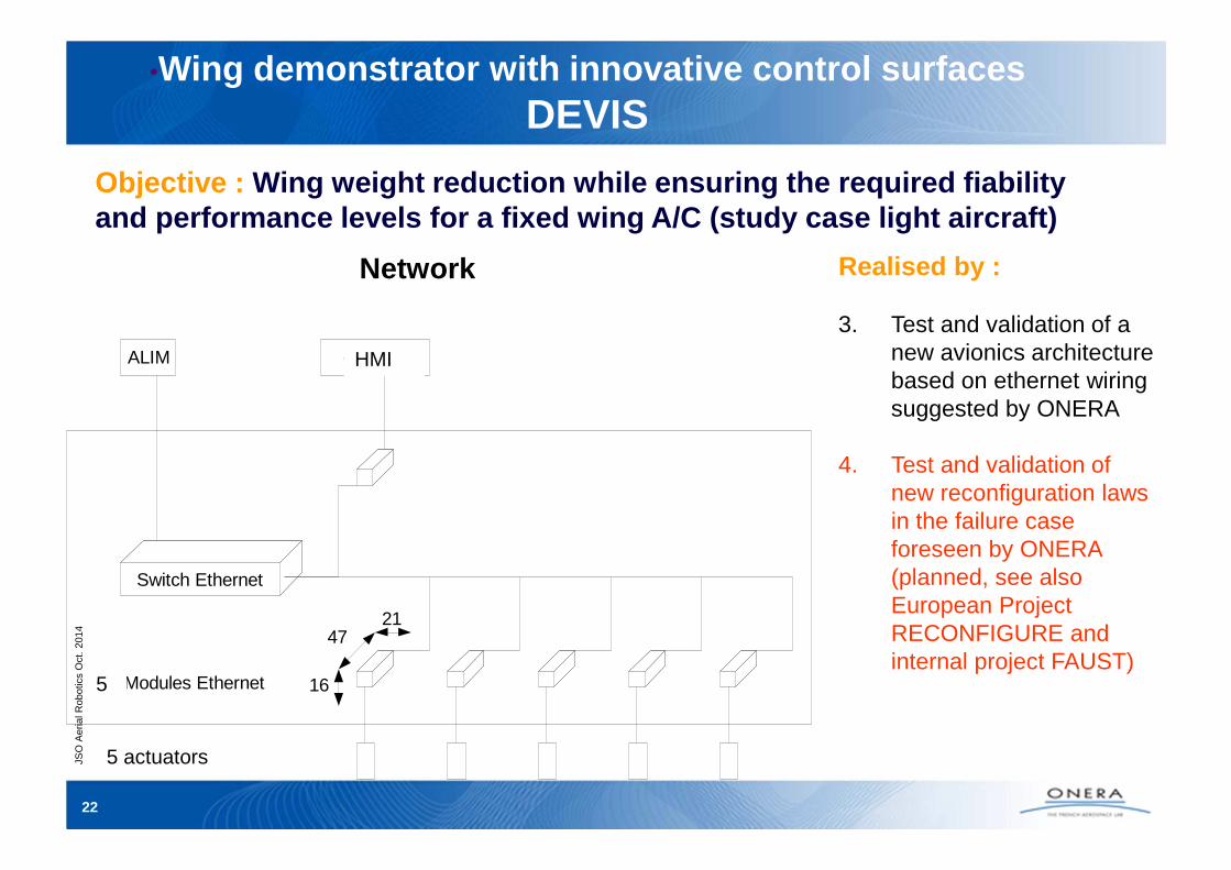
3. Test and validation of a new avionics architecture based on ethernet wiring suggested by ONERA
4. Test and validation of new reconfiguration laws in the failure case foreseen by ONERA (planned, see also European Project RECONFIGURE and internal project FAUST)
Network
HMI
5
5 actuators
•Wing demonstrator with innovative control surfaces DEVIS
Objective : Wing weight reduction while ensuring the required f iability and performance levels for a fixed wing A/C (study case light aircraft)
JSO
Aer
ial R
obot
ics
Oct
. 20
14
23
Realised by :
3. Test and validation of a new avionics architecture based on ethernet wiring suggested by ONERA
4. Test and validation of new reconfiguration laws in the failure case foreseen by ONERA (planned, see also European Project RECONFIGURE and internal project FAUST)
Matériel
Modules :Open Controller OC8S
Arm9 @400Mhz 64M ram, 1G rom
POE, uart, dac, adc, thermal/accelero sensors ...
360mW
SwitchTrendnet TPE-80WS
8 x 15.4W
IEEE802.1 p/Q (Qos/VLAN)
10/100/1000Mbps
Hardware
•Wing demonstrator with innovative control surfaces DEVIS
Objective : Wing weight reduction while ensuring the required f iability and performance levels for a fixed wing A/C (study case light aircraft)