20
1 Questions? Call ADC toll free: 1-800-232-2670 Otoscope Coax Ophthalmoscope Dermascope Throat Illuminator Power Handles Instruction Manual
1
Questions?Call ADC toll free:1-800-232-2670
Otoscope
Coax Ophthalmoscope
Dermascope
Throat Illuminator
Power Handles
Instruction Manual

2
DiagnostixTM EENT InstrumentsTable of Contents
1. A Special Thank You 4
2. Introduction - Intended Use 4
3. Warnings and Precautions 4-5
4. Battery Handles and Initial Use 6-8
5. Instrument Heads 9
6. Diagnostix® Otoscope 9-10
7. Diagnostix® Ophthalmoscope 10-12
8. Diagnostix® Dermascope 12-13
9. Diagnostix® Throat Illuminator 13
10. Replacing the Lamp 13
11. Spare Parts and Accessories 13
12. Cleaning and Disinfection 14
13. Technical Specifications 15
14. Maintenance 15
15. Electromagnetic Compatibility 15-19
16. Warranty 19
17. Quality Standards 20
18. How to Contact Us 20

3
DiagnostixTMOtoscope
DiagnostixTMCoax Ophthalmoscope
DiagnostixTMDermascope
DiagnostixTMThroat Illuminator
DiagnostixTM PMVOtoscope
DiagnostixTM Coax PlusOphthalmoscope

4
1. A SPECIAL THANK YOU
Congratulations on your purchase of an ADC® Diagnostix™ Physical Examinstrument.ADC® professional diagnostic products are the instruments of choice where accuracy and dependability are critical.This feature rich instrument was designed to simplify physical exams and non-invasive diagnostics, and with proper use and care these instruments will providemany years of dependable service.Read this booklet thoroughly before attempting to use your new ADC®
Diagnostix™ EENT instrument.
2. INTRODUCTION - INTENDED USE
These instruments are designed to facilitate examination of the eye, ear,nose, throat, and skin.If you have any questions call our toll-free number or visit our website.Note: Only use ADC® instruments and accessories to ensure safe andfunctional use of this product.
3. WARNINGS AND PRECAUTIONS
You have purchased a high quality ADC® DiagnostixTM instrument which has beenmanufactured to the highest global standards and is subjected to rigorous quality control. Read these instructions for use carefully before putting the unit into operation and keepthem in a safe place.If you should have any questions, call our toll-free number or visit our website. Ouraddress can be found on the last page of this booklet.Please note that all instruments described in these instructions for use are only to be usedby suitably trained personnel.The performance and efficency of these instruments are only guaranteed when genuineADC® parts and accessories are used.Attention: There may be a risk of gases igniting when the instrument is used in thepresence of flammable or combustible gases. Working in areas with goodventilation is recommended.

5
Never attempt to take the instrument apart! There is a danger of life-threateningelectrical shock. Unplug the instrument before cleaning or when disinfecting.Warning:Do not use batteries, electrical cords other than those included with this product orreplacement parts supplied by the manufacturer.Warning:Because prolonged intense light exposure can damage the retina, the use of thedevice for ocular examination should not be unnecessarily prolonged, and the brightness settingshould not exceed what is needed to provide clear visualization of the target structures. Thisdevice should be used with filters that eliminate UV radiation (<400 nm) and, wheneverpossible, filters that eliminate short-wavelength blue light (<420 nm).The retinal exposure dose for a photochemical hazard is a product of the radiance and theexposure time. If the value of radiance were reduced in half, twice the time would be needed toreach the maximum exposure limit.While no acute optical radiation hazards have been identified for direct or indirectophthalmoscopes, it is recommended that the intensity of light directed into the patient’s eye belimited to the minimum level which is necessary for diagnosis. Infants, aphakes and personswith diseased eyes will be at greater risk. The risk may also be increased if the person beingexamined has had any exposure with the same instrument or any other ophthalmic instrumentusing a visible light source during the previous 24 hours. This will apply particularly if the eyehas been exposed to retinal photography.Warning: Otoscope MUST be used with included disposable specula.Warning: This product may contain a chemical known to the state of California tocause cancer, birth defects, or other reproductive harm.
Caution: Not made with natural rubber latex.Attention: Make sure to charge wall plug-in handles for at least 12 hours beforefirst use and for all subsequent charges to ensure optimal capacity and battery life.NOTE: To obtain the greatest performance from your DiagnostixTM Instrument, it isrecommended that the instrument be used within a temperature range of 50°F (10°C) to104°F (40°C), with a 10-95% relative humidity.
Caution: Observe the Operating Instructions
Device double-earthed
ClassificationType-B applied part - Otoscope head with speculum
To learn more, visit our website at: www.adctoday.com.

6
4. BATTERY HANDLES AND INITIAL USE
4.1. FunctionThe ADC® battery handles described in these Operating Instructions serveto supply the instrument heads with power (the lamps are contained intheir respective instrument heads).
4.2. Battery Handle OptionsAll the instrument heads described in these Operating Instructions fit onthe following battery handles and can therefore be individually combined.
For Otoscopes, Ophthalmoscopes, Dermascope, Throat Illuminator,Power Handles.
Wall Mounted Handle #5660E 3.5v, 230v or 120v(with extension unit)
Rechargeable Handle #5560 3.5v(requires desk charger)
Plug-In Rechargeable Handle #5460 3.5v, 230v or 120v
Note: These handles are compatible with ADC® , Riester*, and Welch Allyn*3.5v instrument heads.* Welch Allyn is a registered trademark.* Riester is a registered trademark
4.3. Inserting and Removing RechargeableBatteriesScrew off the battery cap on the lower part of thehandle. Depending on which handle you havepurchased and for what voltage (Fig. 1), insert therechargeable battery into the casing such that thepositive end points toward the top of the handle. Thereis also an arrow next to the plus symbol on therechargeable battery, which shows you the direction to insert into thehandle. Screw the battery cap onto the handle to secure.
(Fig. 1)
7
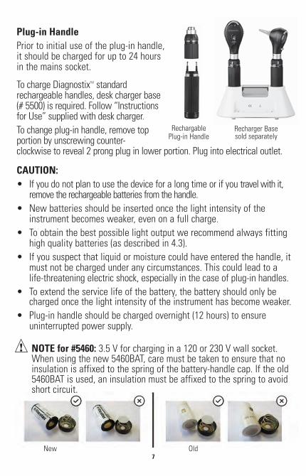
Plug-in HandlePrior to initial use of the plug-in handle,it should be charged for up to 24 hoursin the mains socket.
To charge DiagnostixTM standardrechargeable handles, desk charger base(# 5500) is required. Follow “Instructionsfor Use” supplied with desk charger.To change plug-in handle, remove topportion by unscrewing counter-clockwise to reveal 2 prong plug in lower portion. Plug into electrical outlet.
CAUTION:• If you do not plan to use the device for a long time or if you travel with it,
remove the rechargeable batteries from the handle.• New batteries should be inserted once the light intensity of the
instrument becomes weaker, even on a full charge.• To obtain the best possible light output we recommend always fitting
high quality batteries (as described in 4.3).• If you suspect that liquid or moisture could have entered the handle, it
must not be charged under any circumstances. This could lead to a life-threatening electric shock, especially in the case of plug-in handles.
• To extend the service life of the battery, the battery should only becharged once the light intensity of the instrument has become weaker.
• Plug-in handle should be charged overnight (12 hours) to ensure uninterrupted power supply.
Recharger Basesold separately
RechargablePlug-in Handle
NOTE for #5460: 3.5 V for charging in a 120 or 230 V wall socket.When using the new 5460BAT, care must be taken to ensure that noinsulation is affixed to the spring of the battery-handle cap. If the old5460BAT is used, an insulation must be affixed to the spring to avoidshort circuit.
New Old
8
Waste Disposal:
Please note that rechargeable batteries must be disposed of as specialwaste. You can obtain the relevant information from your local authorityor from your local environmental agency.
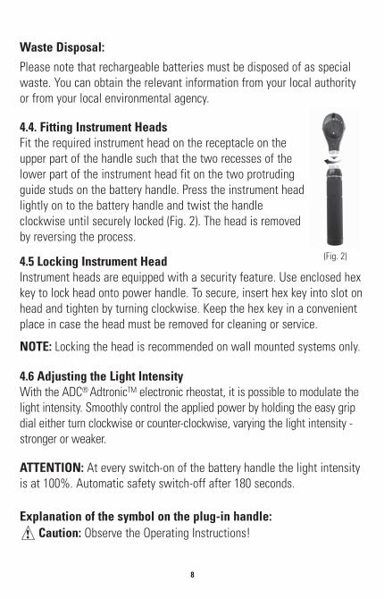
4.4. Fitting Instrument HeadsFit the required instrument head on the receptacle on theupper part of the handle such that the two recesses of thelower part of the instrument head fit on the two protrudingguide studs on the battery handle. Press the instrument headlightly on to the battery handle and twist the handleclockwise until securely locked (Fig. 2). The head is removedby reversing the process.
4.5 Locking Instrument HeadInstrument heads are equipped with a security feature. Use enclosed hexkey to lock head onto power handle. To secure, insert hex key into slot onhead and tighten by turning clockwise. Keep the hex key in a convenientplace in case the head must be removed for cleaning or service.
NOTE: Locking the head is recommended on wall mounted systems only.
4.6 Adjusting the Light IntensityWith the ADC® AdtronicTM electronic rheostat, it is possible to modulate thelight intensity. Smoothly control the applied power by holding the easy gripdial either turn clockwise or counter-clockwise, varying the light intensity -stronger or weaker.
ATTENTION: At every switch-on of the battery handle the light intensityis at 100%. Automatic safety switch-off after 180 seconds.
Explanation of the symbol on the plug-in handle:Caution: Observe the Operating Instructions!
(Fig. 2)

9
5. INSTRUMENT HEADS
All ADC® 3.5v instrument heads are compatible with Riester and WelchAllyn power handles equipped with bayonet style mount.
6. DIAGNOSTIX® OTOSCOPE
6.1. PurposeThe ADC® DiagnostixTM Otoscope described in these OperatingInstructions is produced for illumination and examination of the auditorycanal in combination with the ear specula. The ADC® DiagnostixTMOtoscopes are compatible with Riester, or Welch Allyn speculum.
6.2. Fitting and Removing Ear SpeculaScrew the speculum clockwise until noticeable resistance is felt. Toremove the speculum, twist the speculum counter-clockwise.
6.3 Swivel Lens for MagnificationStandard Series: The swivel lens (3x max.) is fixed tothe device and can be swiveled 360° (Fig. 3). PMV Series: The focusing wheel allows you to adjustthe focusing range. The adjustment wheel moves upand down to focus the lens (Fig. 4).
6.4 Insertion of External Instruments into the EarStandard Series only: If you wish to insert externalinstruments into the ear (e.g. tweezers), you have torotate the swivel lens located on the otoscope head by180°.
6.5 Pneumatic TestTo perform the pneumatic test (examination of theeardrum), an insufflator is required to be connected (soldseparately (#5122N). The tube for the insufflator isattached to the connector port on the right side of theinstrument head (Fig. 5). Now you can carefully insert thenecessary volume of air into the ear canal.
(Fig. 3)
(Fig. 4)
(Fig. 5)

10
6.6 Technical Data of the Lamp
Otoscope XL 3.5 V 3.5 V 720 mA mean life span 15h
Otoscope LED 3.5 V 3.5 V 28 mA mean life span 100,000h
7. DIAGNOSTIX® OPHTHALMOSCOPE7.1. PurposeThe ADC® DiagnostixTM Ophthalmoscope described inthese Operating Instructions is produced for theexamination of the eye.
7.2. Lens Wheel with Correction Lens Thecorrection lens can be adjusted on the lens wheel. Thefollowing correction lenses are available:
Coax 3.5v Ophthalmoscope (Fig. 6).Plus: 1-10, 12, 15, 20, 40Minus: 1-10, 15, 20, 25, 30, 35
Coax Plus 3.5v Ophthalmoscope (Fig. 7).Plus: 1-45 in single stepsMinus: 1-44 in single stepsThe values can be read off in the illuminated fieldof view. Plus values are displayed in green numbers,minus values with red numbers.
7.3. AperturesThe following apertures can be selected with the aperture hand-wheel (Fig. 8).
Switching Aperture(Fig.8
Standard Head(Fig. 6)
Premium Head(Fig.7)
11
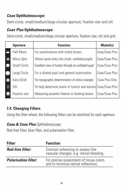
Coax Ophthalmoscope:Semi-circle, small/medium/large circular aperture, fixation star and slit.
Coax Plus Ophthalmoscope:Semi-circle, small/medium/large circular aperture, fixation star, slit and grid.
Aperture Function Model(s)
Half Moon For examinations with turbid lenses Coax/Coax Plus
Micro Spot Allows quick entry into small, undilated pupils Coax/Coax Plus
Small Circle Excellent view of fundus through an undilated pupil Coax/Coax Plus
Large Circle For a dilated pupil and general examination Coax/Coax Plus
Karo (Grid) For topographic determination of retina changes Coax Plus Only
Slit To help determine levels of tumors and lesions Coax/Coax Plus
Fixation star Measuring eccentric fixation or locating lesions Coax/Coax Plus
7.4. Changing FiltersUsing the filter wheel, the following filters can be switched for each aperture.
Coax & Coax Plus Ophthalmoscope:Red-free filter, blue filter, and polarisation filter.
Filter FunctionRed-free filter: Contrast enhancing to assess fine
vascular changes, e.g. retinal bleeding.
Polarisation filter: For precise assessment of tissue colorsand to minimize retinal reflections.

12
Blue filter: For improving recognition of vascularabnormalities or bleeding, for fluorescenceophthalmology.
7.5. Focusing Device (Coax Plus)Fast fine adjustment of the examination area to beobserved is achieved from various distances by turning the focusing daisywheel (Fig. 9).
7.6. Technical Data on the Lamp
Coax 3.5 V ophthalmoscope: 3.5v / 690 mA / average service life 15 h
Coax Plus 3.5 V ophthalmoscope: 3.5v / 29 mA / average service life 100,000 h
8. DIAGNOSTIXTM DERMASCOPE
8.1. PurposeThe Diagnostix® Dermascope described in these Operating Instructions isproduced for early identification of changes of skin pigmentation(malignant melanomas).
8.2. FocusingFocus the magnifying glass by rotating the eyepiecering (Fig. 10).
8.3. Contact PlatesTwo contact plates are supplied:
1) Without a scale.
2) Including a scale of 0 - 10 mm for measuring melanotic skin changes,such as malignant melanoma.
(Fig. 10)
(Fig 9)
13
8.4. Technical Data of LampDermascope LED: 3.5 V 28 mA / mean life span 100,000h
9. DIAGNOSTIXTM THROAT ILLUMINATOR9.1. PurposeThe throat illuminator described in these Operating Instructions isproduced for examination of the oral cavity and pharynx in combinationwith commercial wooden and plastic blades.
9.2. Technical Data of Lamp
Illuminator XL 3.5 V 720 mA mean life span 15hIlluminator LED 3.5 V 28 mA mean life span 100,000h
10. REPLACING THE LAMPAll Instrument HeadsRemove the instrument head off the battery handle. The lamp is locatedat the base of the instrument head. Pull the lamp out of the instrumenthead with thumb and forefinger or a suitable tool. Insert a new lamp.
CAUTION: The pin on the ophthalmoscope lamp must be inserted intothe guide groove on the instrument head.*Use only ADC®, or Riester lamps.
11. SPARE PARTS AND ACCESSORIESFor a complete list of our physical exam instrument spare parts andaccessories, please visit our website at www.adctoday.com.

14
12. CLEANING AND DISINFECTIONCleaning and disinfection of the medical devices serves to protect thepatient, the user and third parties and to preserve the value of the medicaldevices. Due to the product design and the materials used, no definedlimit can be specified for the maximum number of reprocessing cycles thatcan be carried out. The life span of the medical devices is determined bytheir function and by gentle handling of the devices. Defective productsmust undergo the reprocessing procedure described before being returnedfor repair.
Cleaning and Disinfection The instrument heads and handles can becleaned externally with a moist cloth until visually clean. Wipedisinfection as specified by the disinfectant manufacturer. Onlydisinfectants with proven efficacy should be used, taking into account thenational requirements. After disinfection, wipe the instrument down with amoist cloth to remove possible disinfectant residues. The components thatcome into contact with the skin can be rubbed down with alcohol or asuitable disinfectant.
Please Note! • Never immerse the instrument heads and handles in liquids!
Take care to ensure that no liquids get inside the casing!• This item is not approved for automated reprocessing and sterilization.
Single-Use Ear Specula
For single Use Only
WARNING: Repeated use can cause infections.

15
13. TECHNICAL SPECIFICATIONS
Ambient Temperature: 32°F-104°F (0°C to +40°C)Relative Humidity: 30% to 70% non-condensingTransport and StorageTemperature: 14°F-131°F (-10°C to +55°C)Relative Humidity: 10% to 95% non-condensing
14. MAINTENANCE
These instruments and their accessories do not require any specificmaintenance. Should an instrument have to be examined for any specificreason whatsoever, please return it to ADC®.
15. ELECTROMAGNETIC COMPATIBILITY
Medical electrical equipment is subject to special precautionary measureswith regard to electromagnetic compatibility (EMC).Portable and mobile high-frequency communication equipment caninfluence medical electrical equipment. This ME device is intended foroperation in an electromagnetic environment as specified below. The userof the device should ensure that it is operated in such an environment.The ME device must not be used directly next to or arranged in a stackwith other devices. If the device has to be operated near to or in astacked arrangement with other devices, then the ME device should bemonitored in order to verify that it operates as intended in thisarrangement. This ME device is intended exclusively for use byprofessional medical staff. This device can cause radio interference andcan disrupt the operation of equipment nearby. Suitable remedialmeasures, such as for instance re-alignment, re-arrangement of the MEdevice or shielding, can become necessary.

16
HF emissions accordingto CISPR 11
Group 1
EmissionMeasurements
Electromagnetic EnvironmentGuidelines
Guidelines and manufacturer's declaration - electromagnetic emissionsThe DiagnostixTM insrument is intended for operation in an electromagnetic
environment as specified below. The customer or the user of the DiagnostixTMinstrument should ensure that it is used in such an environment.
Compliance
The DiagnostixTM instrument employs HFenergy solely for an internal function. ItsHF emission is therefore very low and itis unlikely that neighboring electronicdevices will be affected by interference.
HF emissions accordingto CISPR 11
Class B
Harmonics emissionsaccording toEC61000-3-2
Not applicable
The DiagnostixTM instrument is intendedfor use in all facilities, including livingquarters and such as are directlyconnected to a public power supply thatalso supplies buildings that are used forresidential purposes.
Voltage fluctuation /flicker emissionsaccording toIEC61000-3-3
Not applicable
17
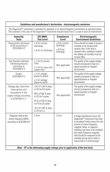
Electrostatic discharge(ESD) according to
IEC61000-4-2
± 6 kV contactdischarge
± 8 kV air discharge
± 6 kV contactdischarge
± 8 kV airdischarge
ImmunityTests
IEC 60601Test Level
ElectromagneticEnvironment Guidelines
Guidelines and manufacturer's declaration - electromagnetic emissions
The DiagnostixTM instrument is intended for operation in an electromagnetic environment as specified below.The customer or the user of the DiagnostixTM instrument should ensure that it is used in such an environment.
Note - UT is the alternating supply voltage prior to application of the test level.
ComplianceLevel
Floors should be made of wood orconcrete or be covered withceramic tiles. If the floor iscovered with a synthetic material,the relative air humidity must beat least 30%.
Fast transient electricalinterference/bursts
according toIEC61000-4-4
± 2 kV for powerlines
± 1 kV for input andoutput lines
3 A/m 3 A/m
Not applicable
The quality of the supply voltageshould correspond to that of atypical business or hospitalenvironment.
SurgesIEC61000-4-5
± 1 kV voltagephase-to-phase
± 2 kV voltagephase-to-earth
Not applicable
The quality of the supply voltageshould correspond to that of atypical business or hospitalenvironment.
Voltage dips, short-timeinterruptions andfluctuations in the
supply voltage accordingto IEC61000-4-11
Magnetic field at themains frequency (50Hz)
according to IEC61000-4-8
<5% UT (>95 % dropin UT) for 0.5 cycles
40% UT (60 % dropin UT) for 5 cycles
70 % UT (30 % dropin UT) for 25 cycles
<5% UT (>95 % dropin UT) for 5 s
Not applicable
The quality of the supply voltageshould correspond to that of atypical business or hospitalenvironment.
If image disturbances occur, theDiagnostixTM instrument may haveto be placed further away from thesources of mains-frequencymagnetic fields, or magneticshielding may have to be installed:the mains-frequency magneticfield should be measured at theintended set-up site in order toensure that it is small enough.

18
Conducted HFinterferenceaccording toIEC61000-4-6Radiated HF
rerference cordingto C61000-4-3
3 Vrms
150 kHz to 80MHz
3 V/m
80 MHz to 2.5GHz
Not applicable
10 V/m
3 V/m
ImmunityTests
IEC 60601Test Level
ElectromagneticEnvironment Guidelines
Guidelines and manufacturer's declaration - electromagnetic immunity
This DiagnostixTM Instrument model is intended for operation in the electromagnetic environment specified below.The customer or the user of this DiagnostixTM instrument should ensure that it is used in such an environment.
ComplianceLevel
Portable and mobile radioequipment should not be usedwithin a distance from theDiagnostixTM instrument, includingcables, that is less than therecommended safety distance ascalculated by the equation that isappropriate for the transmissionfrequency.Recommended safety distance:d = 1.2ìPd = 1.2ìP 80 MHz to 1000 MHzd = 2.3ìP 1400 MHz to 2.5 GHz
Where P is the nominal power ofthe transmitter in Watts (W) asspecified by the manufacturer ofthe transmitter, and d is therecommended safety distance inmeters (m).
The field strength of stationaryradio transmitters should be lessthan the compliance level at allfrequencies as verified by an on-site testa
Interference is possible in thevicinity of equipment marked withthe following symbol
Note 1: At 80 MHz and 800 MHz, the higher value applies.
Note 2: These guidelines may not apply in all situations. The propagation of electromagnetic waves is influenced by reflection and absorption bybuildings, objects and people.
a. The field strength of stationary transmitters, such as base stations of wireless telephones and mobile field radio services, amateur radiostations, AM and FM radio and television transmitters cannot be precisely determined theoretically in advance. In order to determine theelectromagnetic environment due to stationary HF transmitters, an investigation of the location is advisable. If the field strength determinedat the location of the DiagnostixTM Instrument exceeds the compliance level indicated above, then the DiagnostixTM Instrument must bemonitored with regard to its normal operation at each place where it is used. If unusual performance characteristics are observed, additionalmeasures such as re-alignment of the DiagnostixTM Instrument or its removal to another place may be necessary.
b. In the frequency range of 150 kHz to 80 MHz, the field strength should be smaller than 3 V/m.

19
Not applicable
0.01 0.12 0.23
d = 1.2ìP d = 2.3ìP
Nominal power ofthe transmitter
W
150 kHz to 80 MHz
Safety distance that applies to the transmitter frequency m
Recommended safety distances between portable and mobile HF communication devices and the Diagnotix® L
This DiagnostixTM instrument is intended for operation in an electromagnetic environment in which the radiated HF interference ismonitored. The customer or user of this DiagnostixTM instrument can help prevent electromagnetic interference by observing
minimum distances between portable and mobile HF communication equipment (transmitters) and this DiagnostixTM instrumentas recommended below, depending on the maximum output power of the communication equipment.
80 MHz to 1000 MHz 1400 MHz to 2.5GHz
For transmitters whose nominal power is not indicated in the table above, the distance can be determined using the equation belonging tothe respective column, where P is the nominal power of the transmitter in Watts (W) as specified by the manufacturer of the transmitter.
Note 1: At 80 MHz and 1400 MHz, the distance for the higher frequency range applies.
Note 2: These guidelines may not apply in all situations. The propagation of electromagnetic waves is influenced by reflection and absorptionby buildings, objects and people.
0.01 0.38 0.73
1 1.2 2.3
10 3.8 7.3
100 12 23
16. WARRANTY
This DiagnostixTM Instrument is warranted for 2 years on instrumentsand Lifetime on LED lamps, from date of purchase. This warrantyincludes the instrument. The warranty does not apply to damagecaused by improper handling, accidents, improper use, or alterationsmade to the instrument by third parties. The warranty is only valid afterthe product is registered online at www.adctoday.com.

IB p/n 93-5400-00 rev 2 Printed in U.S.A.
Type BF applied part
Made in GermanyInspected and Packaged in the U.S.A.
tel: 631-273-9600toll free: 1-800-232-2670
fax: 631-273-9659
www.adctoday.com
email: [email protected] instructionsfor use
ADC 55 Commerce Drive Hauppauge, NY 11788
ADC (UK) Ltd. Unit 6, PO14 1TH United Kingdom
17. QUALITY STANDARDS
Device standard:This device is manufactured to meet the European and United Statesstandards for:
ISO 62471:2008, ISO 15004, ISO 10942, ISO 15004-1, and ISO 15004-2
Electromagnetic compatibility:Device fulfills the stipulations of the International standard IEC60601-1-2
18. HOW TO CONTACT US
To register your product and obtain further detailed userinformation about our products and services visit us at:
www.adctoday.comand follow the links.
For questions, comments, or suggestions call us toll free at:
1-800-232-2670


