www.tridonic.com 1 Subject to change without notice. Data sheet 04/12-767-7 Electronic ballasts for fluorescent lamps Professional electronic ballast Product description • Average life = 50,000 hours (at max ta. with a failure rate ≤ 0.2 % per 1,000 hours) • Large temperature range (for values see table) • Safety shutdown at end of life • Automatic start after replacement of defective lamps • For emergency lighting systems as per EN 50172 • Constant luminous flux irrespective of fluctuations in mains voltage • For luminaires of protection class 1 and protection class 2 • Insulation Displacement Connection (IDC) terminal for rapid automatic or manual wiring • Temperature protection as per EN 61347-2-3 C5e Technical data AC voltage range 198 – 264 V DC voltage range 176 – 280 V (Lamp start ≥ 198 V DC) Overvoltage protection 320 V AC, 1 h Defined warm start ≤ 1.5 s Operating frequency ≥ 40 kHz Type of protection IP20 È Standards, page 2 Wiring diagrams and installation examples, page 5 PC T5 PRO lp, 14 – 35 W T5 high efficiency and TC-L compact fluorescent lamps (CFL) TC-L T5 side fixing feature Ordering data Type Article number For luminaires with 1 lamp PC 1/14-21-28-35 T5 PRO lp 22176096 For luminaires with 2 lamps PC 2/14-21-28-35 T5 PRO lp 22176097 For luminaires with 3 or 4 lamps PC 3/4/14 T5 PRO lp 22176315 Packaging 280 mm casing: 10 pieces/carton, 960 pieces/pallet Packaging 360 mm casing: 10 pieces/carton, 760 pieces/pallet Specific technical data Lamp wattage Lamp type Type Length L Hole spacing D Weight Lamp wattage Circuit power EEI Current at 50 Hz λ at 50 Hz tc point Ambient temperature ta 220 V 240 V 220 V 240 V For luminaires with 1 lamp 1 x 14 W T5 PC 1/14-21-28-35 T5 PRO lp 280 mm 270 mm 0.20 kg 14.0 W 16.0 W A2 BAT 0.07 A 0.07 A 0.98 0.96 75 °C -25 ... 55 °C 1 x 21 W T5 PC 1/14-21-28-35 T5 PRO lp 280 mm 270 mm 0.20 kg 20.6 W 22.5 W A2 BAT 0.10 A 0.10 A 0.98 0.96 75 °C -25 ... 55 °C 1 x 28 W T5 PC 1/14-21-28-35 T5 PRO lp 280 mm 270 mm 0.20 kg 27.9 W 30.5 W A2 BAT 0.14 A 0.13 A 0.98 0.96 75 °C -25 ... 55 °C 1 x 35 W T5 PC 1/14-21-28-35 T5 PRO lp 280 mm 270 mm 0.20 kg 35.5 W 38.5 W A2 0.18 A 0.17 A 0.98 0.96 75 °C -25 ... 55 °C 1 x 28 W TC-L PC 1/14-21-28-35 T5 PRO lp 280 mm 270 mm 0.20 kg 25.8 W 29.0 W A2 BAT 0.13 A 0.12 A 0.98 0.97 70 °C -25 ... 55 °C For luminaires with 2 lamps 2 x 14 W T5 PC 2/14-21-28-35 T5 PRO lp 360 mm 350 mm 0.26 kg 28.0 W 31.0 W A2 BAT 0.14 A 0.14 A 0.98 0.96 80 °C -25 ... 50 °C 2 x 21 W T5 PC 2/14-21-28-35 T5 PRO lp 360 mm 350 mm 0.26 kg 41.2 W 45.5 W A2 BAT 0.21 A 0.20 A 0.99 0.97 80 °C -25 ... 50 °C 2 x 28 W T5 PC 2/14-21-28-35 T5 PRO lp 360 mm 350 mm 0.26 kg 55.8 W 61.0 W A2 BAT 0.28 A 0.26 A 0.99 0.97 80 °C -25 ... 50 °C 2 x 35 W T5 PC 2/14-21-28-35 T5 PRO lp 360 mm 350 mm 0.26 kg 71.0 W 76.5 W A2 0.35 A 0.33 A 0.99 0.97 80 °C -25 ... 50 °C 2 x 28 W TC-L PC 2/14-21-28-35 T5 PRO lp 360 mm 350 mm 0.26 kg 49.7 W 54.5 W A2 BAT 0.25 A 0.23 A 0.98 0.97 70 °C -25 ... 50 °C For luminaires with 3 or 4 lamps 3 x 14 W T5 PC 3/4/14 T5 PRO lp 360 mm 350 mm 0.25 kg 42.0 W 47.1 W A2 BAT 0.22 A 0.20 A 0.98 0.97 65 °C -25 ... 50 °C 4 x 14 W T5 PC 3/4/14 T5 PRO lp 360 mm 350 mm 0.25 kg 56.0 W 62.3 W A2 BAT 0.29 A 0.26 A 0.99 0.98 70 °C -25 ... 50 °C PHASED OUT
Transcript
www.tridonic.com 1Subject to change without notice.
Data sheet 04/12-767-7
Electronic ballasts for fluorescent lampsProfessional electronic ballast
Product description
•Average life = 50,000 hours (at max ta.
with a failure rate ≤ 0.2 % per 1,000 hours)
•Large temperature range (for values see table)
•Safety shutdown at end of life
•Automatic start after replacement of defective lamps
•For emergency lighting systems as per EN 50172
•Constant luminous flux irrespective of fluctuations in mains voltage
•For luminaires of protection class 1 and protection class 2
DC voltage range 176 – 280 V (Lamp start ≥ 198 V DC)
Overvoltage protection 320 V AC, 1 h
Defined warm start ≤ 1.5 s
Operating frequency ≥ 40 kHz
Type of protection IP20
ÈStandards, page 2
Wiring diagrams and installation examples, page 5
PC T5 PRO lp, 14 – 35 WT5 high efficiency and TC-L compact fluorescent lamps (CFL)
TC-LT5
side fixing feature
Ordering dataType Article numberFor luminaires with 1 lamp
PC 1/14-21-28-35 T5 PRO lp 22176096
For luminaires with 2 lamps
PC 2/14-21-28-35 T5 PRO lp 22176097
For luminaires with 3 or 4 lamps
PC 3/4/14 T5 PRO lp 22176315Packaging 280 mm casing: 10 pieces/carton, 960 pieces/pallet
Packaging 360 mm casing: 10 pieces/carton, 760 pieces/pallet
Specific technical dataLamp
wattageLamp
typeType Length L Hole
spacing DWeight Lamp
wattageCircuit power
EEI Current at 50 Hz λ at 50 Hz tc point Ambienttemperature ta220 V 240 V 220 V 240 V
For luminaires with 1 lamp1 x 14 W T5 PC 1/14-21-28-35 T5 PRO lp 280 mm 270 mm 0.20 kg 14.0 W 16.0 W A2 BAT 0.07 A 0.07 A 0.98 0.96 75 °C -25 ... 55 °C
1 x 21 W T5 PC 1/14-21-28-35 T5 PRO lp 280 mm 270 mm 0.20 kg 20.6 W 22.5 W A2 BAT 0.10 A 0.10 A 0.98 0.96 75 °C -25 ... 55 °C
1 x 28 W T5 PC 1/14-21-28-35 T5 PRO lp 280 mm 270 mm 0.20 kg 27.9 W 30.5 W A2 BAT 0.14 A 0.13 A 0.98 0.96 75 °C -25 ... 55 °C
1 x 35 W T5 PC 1/14-21-28-35 T5 PRO lp 280 mm 270 mm 0.20 kg 35.5 W 38.5 W A2 0.18 A 0.17 A 0.98 0.96 75 °C -25 ... 55 °C
1 x 28 W TC-L PC 1/14-21-28-35 T5 PRO lp 280 mm 270 mm 0.20 kg 25.8 W 29.0 W A2 BAT 0.13 A 0.12 A 0.98 0.97 70 °C -25 ... 55 °C
For luminaires with 2 lamps2 x 14 W T5 PC 2/14-21-28-35 T5 PRO lp 360 mm 350 mm 0.26 kg 28.0 W 31.0 W A2 BAT 0.14 A 0.14 A 0.98 0.96 80 °C -25 ... 50 °C
2 x 21 W T5 PC 2/14-21-28-35 T5 PRO lp 360 mm 350 mm 0.26 kg 41.2 W 45.5 W A2 BAT 0.21 A 0.20 A 0.99 0.97 80 °C -25 ... 50 °C
2 x 28 W T5 PC 2/14-21-28-35 T5 PRO lp 360 mm 350 mm 0.26 kg 55.8 W 61.0 W A2 BAT 0.28 A 0.26 A 0.99 0.97 80 °C -25 ... 50 °C
2 x 35 W T5 PC 2/14-21-28-35 T5 PRO lp 360 mm 350 mm 0.26 kg 71.0 W 76.5 W A2 0.35 A 0.33 A 0.99 0.97 80 °C -25 ... 50 °C
2 x 28 W TC-L PC 2/14-21-28-35 T5 PRO lp 360 mm 350 mm 0.26 kg 49.7 W 54.5 W A2 BAT 0.25 A 0.23 A 0.98 0.97 70 °C -25 ... 50 °C
For luminaires with 3 or 4 lamps3 x 14 W T5 PC 3/4/14 T5 PRO lp 360 mm 350 mm 0.25 kg 42.0 W 47.1 W A2 BAT 0.22 A 0.20 A 0.98 0.97 65 °C -25 ... 50 °C
4 x 14 W T5 PC 3/4/14 T5 PRO lp 360 mm 350 mm 0.25 kg 56.0 W 62.3 W A2 BAT 0.29 A 0.26 A 0.99 0.98 70 °C -25 ... 50 °C
PHASED OUT
www.tridonic.com 2Subject to change without notice.
Data sheet 04/12-767-7
Electronic ballasts for fluorescent lampsProfessional electronic ballast
StandardsEN 55015EN 61347-2-4EN 61347-2-3EN 60929EN 61000-3-2EN 61547in accordance with EN 50172 IEC 68-2-64 FhIEC 68-2-29 EbIEC 68-2-30
Lamp starting characteristics Warm start Starting time 1.5 secs with AC and DC operationCathode heating will be reduced after preheat time
AC operationMains voltage:220–240 V 50/60 Hz198–264 V 50/60 Hz including safety tolerance (±10 %)202–254 V 50/60 Hz including performance tolerance (+6 % / -8 %)
DC operation 220–240 V 0 Hz198–280 V 0 Hz certain lamp start176–280 V 0 Hz operating rangeLight output level in DC operation: 100 %
Emergency lighting Use in emergency lighting installations according to EN 50172 or for emergency luminaires according to EN 61347-2-3 appendix J.
Instant start after mains interruption < 0.5 s
Intelligent Voltage GuardIntelligent Voltage Guard is the name of the new electronic monitor from Tridonic. This inno vative feature of the PC PRO family of control gear from Tridonic immediately shows if the mains voltage rises above or falls below certain thresholds. Measu-res can then be taken quickly to prevent damage to the control gear.•Ifthemainsvoltagerisesabove306Vthe
lamps start flashing on and off.•Thissignal“demands”disconnectionofthe
power supply to the lighting system.•Ifthemainsvoltagefallsbelow150Vthecontrol
gear automatically disconnects the lamp circuit to protect the control gear from being irreparably damaged.
Smart HeatingInnovative heating circuit. Reduced filament heating after lamp ignition.
Mains currents in DC operation
Type lamp type wattagemains current at
Un = 220 VDC
mains current atUn = 240 VDC
PC 1/14-21-28-35 T5 PRO lp T5 1x14 W 73 mA 67 mAPC 2/14-21-28-35 T5 PRO lp T5 2x14 W 141 mA 129 mAPC 3/4/14 T5 PRO lp T5 3x14 W 217 mA 201 mAPC 3/4/14 T5 PRO lp T5 4x14 W 287 mA 264 mAPC 1/14-21-28-35 T5 PRO lp T5 1x21 W 102 mA 94 mAPC 2/14-21-28-35 T5 PRO lp T5 2x21 W 207 mA 190 mAPC 1/14-21-28-35 T5 PRO lp T5 1x28 W 139 mA 127 mAPC 2/14-21-28-35 T5 PRO lp T5 2x28 W 277 mA 254 mAPC 1/14-21-28-35 T5 PRO lp TC-L 1x28 W 125 mA 115 mAPC 2/14-21-28-35 T5 PRO lp TC-L 2x28 W 250 mA 230 mAPC 1/14-21-28-35 T5 PRO lp T5 1x35 W 175 mA 160 mAPC 2/14-21-28-35 T5 PRO lp T5 2x35 W 348 mA 319 mA
Harmonic distortion in the mains supply
Type lamp type wattageTHD
at 230 V / 50 HzPC 1/14-21-28-35 T5 PRO lp T5 1x14 W < 12 %PC 2/14-21-28-35 T5 PRO lp T5 2x14 W < 12 %PC 3/4/14 T5 PRO lp T5 3x14 W < 10 %PC 3/4/14 T5 PRO lp T5 4x14 W < 10 %PC 1/14-21-28-35 T5 PRO lp T5 1x21 W < 10 %PC 2/14-21-28-35 T5 PRO lp T5 2x21 W < 10 %PC 1/14-21-28-35 T5 PRO lp T5 1x28 W < 10 %PC 2/14-21-28-35 T5 PRO lp T5 2x28 W < 10 %PC 1/14-21-28-35 T5 PRO lp TC-L 1x28 W < 10 %PC 2/14-21-28-35 T5 PRO lp TC-L 2x28 W < 10 %PC 1/14-21-28-35 T5 PRO lp T5 1x35 W < 10 %PC 2/14-21-28-35 T5 PRO lp T5 2x35 W < 10 %
Output voltage
Type lamp type wattage Uout
PC 1/14-21-28-35 T5 PRO lp T5 1x14 W 300 VPC 2/14-21-28-35 T5 PRO lp T5 2x14 W 400 VPC 3/4/14 T5 PRO lp T5 3x14 W 400 VPC 3/4/14 T5 PRO lp T5 4x14 W 400 VPC 1/14-21-28-35 T5 PRO lp T5 1x21 W 300 VPC 2/14-21-28-35 T5 PRO lp T5 2x21 W 400 VPC 1/14-21-28-35 T5 PRO lp T5 1x28 W 300 VPC 2/14-21-28-35 T5 PRO lp T5 2x28 W 400 VPC 1/14-21-28-35 T5 PRO lp TC-L 1x28 W 300 VPC 2/14-21-28-35 T5 PRO lp TC-L 2x28 W 400 VPC 1/14-21-28-35 T5 PRO lp T5 1x35 W 300 VPC 2/14-21-28-35 T5 PRO lp T5 2x35 W 400 V
Ballast lumen factor (EN 60929 8.1)
Type lamp type wattageAC/DC-BLF
at U = 198–254 V, 25 °CPC 1/14-21-28-35 T5 PRO lp T5 1x14 W 1.00PC 2/14-21-28-35 T5 PRO lp T5 2x14 W 1.00PC 3/4/14 T5 PRO lp T5 3x14 W 1.00PC 3/4/14 T5 PRO lp T5 4x14 W 1.00PC 1/14-21-28-35 T5 PRO lp T5 1x21 W 1.00PC 2/14-21-28-35 T5 PRO lp T5 2x21 W 1.00PC 1/14-21-28-35 T5 PRO lp T5 1x28 W 1.00PC 2/14-21-28-35 T5 PRO lp T5 2x28 W 1.00PC 1/14-21-28-35 T5 PRO lp TC-L 1x28 W 0.93PC 2/14-21-28-35 T5 PRO lp TC-L 2x28 W 0.93PC 1/14-21-28-35 T5 PRO lp T5 1x35 W 1.00PC 2/14-21-28-35 T5 PRO lp T5 2x35 W 1.00
PHASED OUT
www.tridonic.com 3Subject to change without notice.
Data sheet 04/12-767-7
Electronic ballasts for fluorescent lampsProfessional electronic ballast
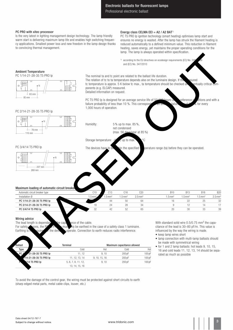
PC PRO with xitec processorIs the very latest in lighting management design technology. The lamp friendly warm start is delivering maximum lamp life and enables high switching frequen-cy applications. Smallest power loss and new freedom in the lamp design thanks to convincing thermal management.
Energy class CELMA EEI = A2 / A2 BAT1)
PC T5 PRO lp ignition technology (smart heating) optimises lamp start and ensures no energy is wasted. After the lamp has struck the filament heating is reduced automatically to a defined minimum value. This reduction in filament heating, saves energy, yet maintains the proper operating conditions for the lamp. The lamp is always operated within specification.
1) according to the EU directives on ecodesign requirements (EC) No. 245/2009
and (EC) No. 347/2010
95 mm63 mm
tc
Ambient Temperature PC 1/14-21-28-35 T5 PRO lp
110 mm78 mm
tc
PC 2/14-21-28-35 T5 PRO lp
The nominal ta and tc point are related to the ballast life duration.The relation of tc to ta temperature depends also on the luminaire design. If the measured tc temperature is approx. 5 K below tc max., ta temperature should be checked and eventually critical com-ponents (e.g. ELCAP) measured. Detailed information on request. PC T5 PRO lp is designed for an average service life of 50,000 hours under reference conditions and with a failure probability of less than 10 %. This corresponds to an average failure rate of 0.2 % for every1,000 hours of operation.
PC 3/4/14 T5 PRO lp
269 mm237 mm
tc
Maximum loading of automatic circuit breakersAutomatic circuit breaker type C10 C13 C16 C20 B10 B13 B16 B20
PC 1/14-21-28-35 T5 PRO lp 32 44 50 64 16 22 25 32
PC 2/14-21-28-35 T5 PRO lp 18 24 28 34 9 12 14 17
PC 3/4/14 T5 PRO lp 32 42 52 65 20 30 33 39
Ballast Terminal Maximum capacitance allowed
Type Cold Hot Cold Hot
PC 1/14-21-28-35 T5 PRO lp 11, 12 9, 10 200 pF 100 pF
PC 2/14-21-28-35 T5 PRO lp 11, 12, 13, 14 9, 10, 15, 16 200 pF 100 pF
PC 3/4/14 T5 PRO lp 5, 6, 7, 8, 11, 12,13, 14, 15, 16
9, 10 200 pF 100 pF
Wiring adviceThe lead length is dependant on the capacitance of the cable.For safety reasons, the PC T5 PRO lp must only be earthed in the case of a safety class 1 luminaire. Earthing is not required for the device to operate. Connection to earth reduces radio interference.
With standard solid wire 0.5/0.75 mm² the capa-citance of the lead is 30–80 pF/m. This value is influenced by the way the wiring is made. •keeplampwiresshort•lampconnectionwithmulti-lampballastsshould
be made with symmetrical wiring•for1and2lampballasts:hotleads9,10,15,
16 and cold leads 11, 12, 13, 14 should be sepa-rated as much as possible
To avoid the damage of the control gear, the wiring must be protected against short circuits to earth(sharp edged metal parts, metal cable clips, louver, etc.)
Humidity: 5 % up to max. 85 %, not condensed (max. 56 days/year at 85 %)
Storage temperature: -40 °C up to max. +80 °C
The devices have to be within the specified temperature range (ta) before they can be operated.
PHASED OUT
www.tridonic.com 4Subject to change without notice.
Data sheet 04/12-767-7
Electronic ballasts for fluorescent lampsProfessional electronic ballast
RFITridonic ballasts are RFI protected in accordance with EN 55015. To operate the luminaire correctly and to minimise RFI we recommend the following instruc-tions:•Connectiontothelampsofthe“hotleads”mustbekeptasshortaspossible
(marked with *)•Mainsleadsshouldbekeptapartfromlampleads(ideally5–10cmdistance)•Donotrunmainsleadsadjacenttotheelectronicballast•Twistthelampleads•Keepthedistanceoflampleadsfromthemetalworkaslargeaspossible•Ballastmustbeearthed,eitherovertheterminaloroverthemountingscrew
of the ballast•Mainswiringtobetwistedwhenthroughwiring•Keepthemainsleadsinsidetheluminaireasshortaspossible
Defective lamp If a lamp is defective, the ballast switches off and goes into standby. There is an automatic restart once the lamp has been changed.
Loosen wire through twisting and pulling
Side fixing feature
Screw M4, screw head diameter 8–10 mm
8 – 9 mm
wire preparation:0.5 – 0.75 mm²
IDC interface•solidwirewithacrosssectionof0.5mm²accordingtothespecification from WAGO
Isolation and electric strength testing of luminairesElectronic devices can be damaged by high voltage. This has to be considered during the routine testing of the luminaires in production.
According to IEC 60598-1 Annex Q (informative only!) or ENEC 303-Annex A, each luminaire should be submitted to an isolation test with 500 V DC for 1 second. This test voltage should be connected between the interconnected phase and neutral terminals and the earth terminal. The isolation resistance must be at least 2 MΩ.
As an alternative, IEC 60598-1 Annex Q describes a test of the electrical strength with 1500 V AC (or 1.414 x 1500 V DC). To avoid damage to the electronic devices this test must not be conducted.
Additional information
Additional technical information at www.tridonic.com → Technical Data
Guarantee conditions at www.tridonic.com → ServicesNo warranty if device was opened.
PHASED OUT
www.tridonic.com 5Subject to change without notice.
Data sheet 04/12-767-7
Electronic ballasts for fluorescent lampsProfessional electronic ballast
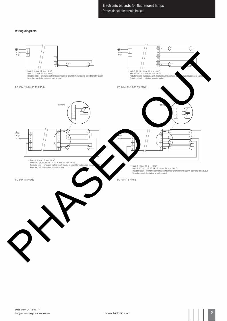
PC 1/14-21-28-35 T5 PRO lp PC 2/14-21-28-35 T5 PRO lp
34
2
1211109
leads 9, 10 max. 1.0 m (< 100 pF)leads 11, 12 max. 2.0 m (< 200 pF)Protection class I - luminaires: earth of ballast housing or ground terminal required (according to IEC 60598)Protection class II - luminaires: no earth required
1615
leads 9, 10, 15, 16 max. 1.0 m (< 100 pF)leads 11, 12, 13, 14 max. 2.0 m (< 200 pF)Protection class I - luminaires: earth of ballast housing or ground terminal required (according to IEC 60598)Protection class II - luminaires: no earth required
1434
2
131211109
1615
leads 9, 10 max. 1.0 m (< 100 pF)leads 5, 6, 7, 8, 11, 12, 13, 14, 15, 16 max. 2.0 m (< 200 pF)Protection class I - luminaires: earth of ballast housing or ground terminal required (according to IEC 60598)Protection class II - luminaires: no earth required
1434
2
131211109
5678
14131211
alternative
1615
leads 9, 10 max. 1.0 m (< 100 pF)leads 5, 6, 7, 8, 11, 12, 13, 14, 15, 16 max. 2.0 m (< 200 pF)Protection class I - luminaires: earth of ballast housing or ground terminal required (according to IEC 60598)Protection class II - luminaires: no earth required