Page 1
OUTAGE PERFORMANCE OF
COOPERATIVE COGNITIVE RELAY
NETWORKS
By
Nusrat Ahmed Surobhi
SUBMITTED IN PARTIAL FULFILLMENT OF THE
REQUIREMENTS FOR THE DEGREE OF
MASTERS OF ENGINEERING BY RESEARCH IN ELECTRICAL ENGINEERING
AT
VICTORIA UNIVERSITY
MELBOURNE, AUSTRALIA
SEPTEMBER 2009
c⃝ Copyright by Nusrat Ahmed Surobhi, 2010
Page 2
VICTORIA UNIVERSITY
School of Engineering and Science
“I, Nusrat Ahmed Surobhi, declare that the Masters by Research
thesis entitled Outage Performance of Cooperative Cognitive
Relay Networks is no more than 60,000 words in length including
quotes and exclusive of tables, figures, appendices, bibliography,
references and footnotes. This thesis contains no material that has been
submitted previously, in whole or in part, for the award of any other
academic degree or diploma. Except where otherwise indicated, this
thesis is my own work”.
Dated: September 2009
Signature of Author:Nusrat Ahmed Surobhi
ii
Page 3
VICTORIA UNIVERSITY
Date: September 2009
Author: Nusrat Ahmed Surobhi
Title: Outage Performance of Cooperative Cognitive
Relay Networks
Department: School of Engineering and Science
Degree: M. Eng. by Research Year: 2010
Permission is herewith granted to Victoria University to circulate and to
have copied for non-commercial purposes, at its discretion, the above title
upon the request of individuals or institutions.
Signature of Author
THE AUTHOR RESERVES OTHER PUBLICATION RIGHTS, ANDNEITHER THE THESIS NOR EXTENSIVE EXTRACTS FROM IT MAYBE PRINTED OR OTHERWISE REPRODUCED WITHOUT THE AUTHOR’SWRITTEN PERMISSION.
THE AUTHOR ATTESTS THAT PERMISSION HAS BEEN OBTAINEDFOR THE USE OF ANY COPYRIGHTED MATERIAL APPEARING IN THISTHESIS (OTHER THAN BRIEF EXCERPTS REQUIRING ONLY PROPERACKNOWLEDGEMENT IN SCHOLARLY WRITING) AND THAT ALL SUCHUSE IS CLEARLY ACKNOWLEDGED.
iii
Page 4
iv
To My Father
���� �����
Page 5
Abstract
This thesis considers the incorporation of cooperative relays into a cognitive radio
network. Cognitive radio is a potential solution to the growing scarcity of radio spec-
trum and the increased demand for wireless services. Cooperative relay networks
can help cognitive radios to improve their utilisation by reducing their transmit
power. This allows a reduction in their interference footprint and increases their
probability of accessing licensed spectrum, improving throughput, and/or coverage.
A cognitive relay network model has been analysed to derive the closed-form out-
age probability expressions for the repetition-based and selection-based protocols.
Both decode-and-forward and amplify-and-forward relaying schemes have been em-
ployed for these protocols. When the probability of spectrum availability is unity,
the cognitive relay behaves as a conventional cooperative relay. An identical and
independently distributed slow fading Rayleigh channel model has been assumed in
the analysis. The outage probability expressions are valid for arbitrary signal-to-
noise ratios. This is an improvement on the previously published work which was
limited to high signal-to-noise ratio regimes.
The derived expressions are generic and validated by simulations for a specified
scenario. If the probability of spectrum availability is 0.7, then the introduction of
cognitive relay gains more than 5 dB equivalent signal-to-noise ratio improvement
over the non-relay case. A further gain of up to 12 dB is possible if the proba-
bility of spectrum availability increases to unity. Selection-based relaying scheme
outperformed the repetition-based relaying scheme.
The simulation results exactly match the analytical results for the decode-and-
forward relaying scheme. However, for the amplify-and-forward relaying scheme,
the simulation results are a tight upper bound at low signal-to-noise ratios (0 dB-10
v
Page 6
vi
dB) and match exactly at medium to high signal-to-noise ratios.
Page 7
Acknowledgement
My Masters of Engineering by Research study at Victoria University, Melbourne,
Australia has been a journey of discovery and professional growth. I owe thanks to
many people for where I have arrived today.
At first, I would like to acknowledge the guidance and the support of my su-
pervisor Professor Mike Faulkner. Professor Faulkner’s enthusiasm and passion for
research inspired me to carry on my work. He always had the patience to listen and
provide feedbacks on my work. His feedbacks showed many different approaches to
solve a research problem enriching my research experience.
I would also like to acknowledge the assistance of Dr. Himal Suraweera (former
postdoctoral fellow, Centre of Telecommunication and Microelectronics, Victoria
University) during my study. Dr. Suraweera always had his door open for me to
walk in with my queries. He taught me a lot about the cooperative relay networks
and the cognitive radio technology. I appreciate his exceptionally strong knowledge
in these areas and his willingness to help me.
I have a great appreciation to the Department of Education, Employment and
Workplace Relations (DEEWR) for the Endeavour International Postgraduate Re-
search Scholarship (EIPRS) and to Victoria University for the living allowance.
Without these funding supports, I would have never been able to complete the
study.
Ms Lesley Birch, admissions and scholarships coordinator, and Ms Elizabeth
Smith, student advice officer (research & graduate studies), have helped in many
occasions; I can not thank them enough. Furthermore, I would like to thank Ms
Angela Rojter, international student writing support, for her continuous support
during the writing up phase of my thesis.
vii
Page 8
viii
I would like to thank the people of Bangladesh for supporting my undergraduate
study in Bangladesh. A special thank goes to Rajshahi University of Engineering
and Technology for approving an extra-ordinary study leave to pursue this degree.
I would like to thank my family for their unconditional love and support during
my study in abroad. Till today, there has not been a single day in which they have
not called me up. This helped me to get over home sickness and concentrate on my
study here. They have always been my greatest assets.
Last but not least, I would like to thank other co-researchers in rooms G 217
and G 218 for having a wonderful time with them.
Page 9
List of Publications
Conference & Workshops Publications
• Nusrat. A. Surobhi and Mike Faulkner, “Closed-Form Outage Probabil-
ity Analysis of a Diamond Relay Network with Opportunistic Spectrum Ac-
cess,” Proc. of IEEE ISWPC 2009, pp 1-5, 11-13 February, 2009, Melbourne,
Australia.
• Nusrat. A. Surobhi and Mike Faulkner, “Outage Probability Analysis of
a Diamond Relay Network with Opportunistic Spectrum Access,” Proc. of
IEEE ICSPCS 2008, pp 1-5, 15-17 December, 2008, Gold Coast, Australia.
• Nusrat. A. Surobhi and Mike Faulkner, “Outage Probability Analysis of
a Two Relay Network with Opportunistic Spectrum Access,” ACoRN Work-
shop on Cooperative Wireless Communications, 16 July, 2008, Melbourne,
Australia.
• Himal. A. Suraweera, Peter. J. Smith, Nusrat. A. Surobhi, “Exact Out-
age Probability of Cooperative Diversity with Opportunistic Spectrum Ac-
cess,” Cognitive and Cooperative Wireless Networks Workshop, ICC 2008, 19-
23 May, 2008, Beijing, China.
• Nusrat. A. Surobhi and Mike Faulkner, “Exact Outage Probability Analysis
of a Diamond Relay Network with Opportunistic Spectrum Access,” ACoRN
Workshop on Cooperative Wireless Communications, 8 July, 2009, Sydney,
Australia.
ix
Page 10
x
Poster Publications
• Nusrat. A. Surobhi, Himal. A. Suraweera and Mike Faulkner, “A Two
Relay Opportunistic Amplify-and-forward Network with Selection coopera-
tion,” ACoRN Workshop on Cooperative Wireless Communications, 16 July,
2008, Melbourne, Australia.
• Nusrat. A. Surobhi, Himal. A. Suraweera and Mike Faulkner, “Outage Per-
formance of Selection Cooperation in a Cognitive Relay Network, ” Australian
Communications TheoryWorkshop, 30 January-1 February, 2008, Christchurch,
New Zealand.
• Nusrat. A. Surobhi, Himal. A. Suraweera and Mike Faulkner, “Outage
Performance of Selection Cooperation in a Amplify-and forward Cognitive
Relay Network ,” Faculty of Health, Engineering and Science Seminar Day,
Victoria Univerty, 31 October, 2008, Melbourne, Australia.
Page 11
Acronyms
Acronyms Definition
3G third generation
4G fourth generation
AC alternating current
ACMA australian communication and media authority
AF amplify-and-forward
AM amplitude modulated
AWGN additive white gaussian noise
BPSK binary phase shift keying
CDF cumulative density function
CDMA code division multiple access
CROWNCOM conference on cognitive radio oriented wireless networks
and communications
CSI channel state information
DF decode-and-forward
DySPAN dynamic spectrum access networks
e2e end-to-end
EGC equal gain combining
FCC federal communication commission
FM frequency modulated
GSM global system for mobile communication
IEEE institute of electrical and electronics engineers
MAC media access control
xi
Page 12
xii
MIMO multiple input multiple output
MQAM multilevel quadrature amplitude modulation
MRC maximal ratio combining
MGF moment generating function
NOI notice of inquiry
NPRM notice of proposed rule making
OFDMA orthogonal frequency division multiple access
PDA personal digital assistant
PDF probability density function
PSD power spectral density
QoS quality of service
QPSK quadrature phase shift keying
RF radio frequency
R-D relay-destination
RV random variable
SC selection combining
SC-FDMA single carrier-frequency division multiple access
SNR signal-to-noise ratio
S-R-D source-relay-destination
S-R source-relay
TDMA time division multiple access
Page 13
xiii
TV tele-vision
UHF ultra high frequency
VHF very high frequency
WRAN wireless regional area networks
WWW world wide web
Page 14
Table of Contents
Table of Contents xiv
List of Tables xv
List of Figures xvii
1 Introduction 1
1.1 Cognitive Radios . . . . . . . . . . . . . . . . . . . . . . . . . . . . . 1
1.1.1 Background on Cognitive Radio . . . . . . . . . . . . . . . . . 5
1.1.2 Classifications and Characteristics . . . . . . . . . . . . . . . . 10
1.1.3 Application Areas . . . . . . . . . . . . . . . . . . . . . . . . . 16
1.2 Challenges of Cognitive Radio . . . . . . . . . . . . . . . . . . . . . . 18
1.2.1 A Potential Solution ‘Cooperative Relaying’ . . . . . . . . . . 18
1.3 Contributions . . . . . . . . . . . . . . . . . . . . . . . . . . . . . . . 20
1.4 Structure of the Thesis . . . . . . . . . . . . . . . . . . . . . . . . . . 22
2 Background and Literature Survey 24
2.1 Cooperative Relay Network . . . . . . . . . . . . . . . . . . . . . . . 24
2.1.1 Background on Cooperative Relay Networks . . . . . . . . . . 25
2.1.2 Cooperative Relay Network Model . . . . . . . . . . . . . . . 26
2.1.3 Cooperative Relaying Schemes . . . . . . . . . . . . . . . . . . 30
2.1.4 Combining Techniques . . . . . . . . . . . . . . . . . . . . . . 34
2.2 Cognitive Relay Networks . . . . . . . . . . . . . . . . . . . . . . . . 36
2.2.1 Repetition-Based Cognitive Relay Network . . . . . . . . . . . 39
2.2.2 Selection-Based Cognitive Relay Networks . . . . . . . . . . . 40
2.3 Performance Metrics . . . . . . . . . . . . . . . . . . . . . . . . . . . 41
2.4 Summary . . . . . . . . . . . . . . . . . . . . . . . . . . . . . . . . . 42
3 Repetition-Based Cognitive Relay Network 44
3.1 Network and Channel Model of Repetition-Based Cognitive Relay
Network . . . . . . . . . . . . . . . . . . . . . . . . . . . . . . . . . . 44
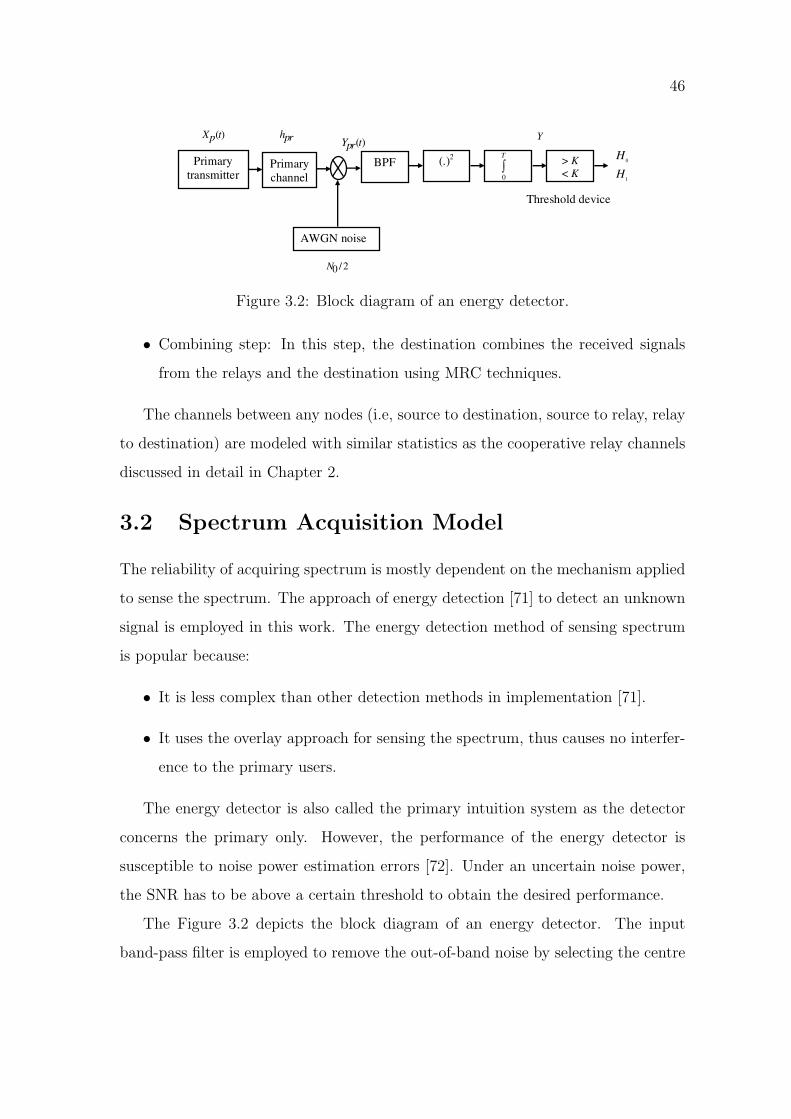
3.2 Spectrum Acquisition Model . . . . . . . . . . . . . . . . . . . . . . . 46
xiv
Page 15
xv
3.3 Cooperative Spectrum Sensing . . . . . . . . . . . . . . . . . . . . . . 49
3.4 Outage Probability . . . . . . . . . . . . . . . . . . . . . . . . . . . . 50
3.4.1 Decode-and-Forward (DF) Cooperative Relay Networks . . . . 50
3.4.2 Decode-and-Forward (DF) Cognitive Relay Networks . . . . . 55
3.4.3 Amplify-and-Forward (AF) Cooperative Relay Networks . . . 56
3.4.4 Amplify-and-Forward (AF) Cognitive Relay Networks . . . . . 60
3.5 Results and Discussions . . . . . . . . . . . . . . . . . . . . . . . . . 61
3.6 Summary . . . . . . . . . . . . . . . . . . . . . . . . . . . . . . . . . 67
4 Selection-Based Cognitive Relay Network 69
4.1 Network Model of Selection-Based Cognitive Relay Network . . . . . 69
4.2 Selection Criterion . . . . . . . . . . . . . . . . . . . . . . . . . . . . 70
4.3 Outage Probability . . . . . . . . . . . . . . . . . . . . . . . . . . . . 72
4.3.1 Decode-and-Forward (DF) Selection-Based Cooperative Relay
Networks . . . . . . . . . . . . . . . . . . . . . . . . . . . . . 72
4.3.2 Decode-and-Forward (DF) Selection-Based Cognitive Relay
Networks . . . . . . . . . . . . . . . . . . . . . . . . . . . . . 74
4.3.3 Amplify-and-Forward (AF) Selection-Based Cooperative Re-
lay Networks . . . . . . . . . . . . . . . . . . . . . . . . . . . 74
4.3.4 Amplify-and-Forward (AF) Selection-Based Cognitive Relay
Networks . . . . . . . . . . . . . . . . . . . . . . . . . . . . . 76
4.4 Results and Discussions . . . . . . . . . . . . . . . . . . . . . . . . . 77
4.5 Summary . . . . . . . . . . . . . . . . . . . . . . . . . . . . . . . . . 81
5 Conclusion and Further Research 83
5.1 Conclusions . . . . . . . . . . . . . . . . . . . . . . . . . . . . . . . . 83
5.2 Further Research . . . . . . . . . . . . . . . . . . . . . . . . . . . . . 86
Bibliography 89
Page 16
List of Tables
1.1 Accommodated applications in different frequency bands [3]. . . . . . 2
1.2 A comparison between 3G and 4G wireless communication. . . . . . . 6
5.1 A summary of derived outage probability expressions. . . . . . . . . . 87
xvi
Page 17
List of Figures
1.1 Allocation of radio spectrum, Australia. . . . . . . . . . . . . . . . . . 3
1.2 Utilization of radio spectrum in Melbourne, Australia. . . . . . . . . . 4
1.3 Guard band utilization to accommodate new applications and users. . 5
1.4 Haykin’s model of a cognitive radio. . . . . . . . . . . . . . . . . . . . 7
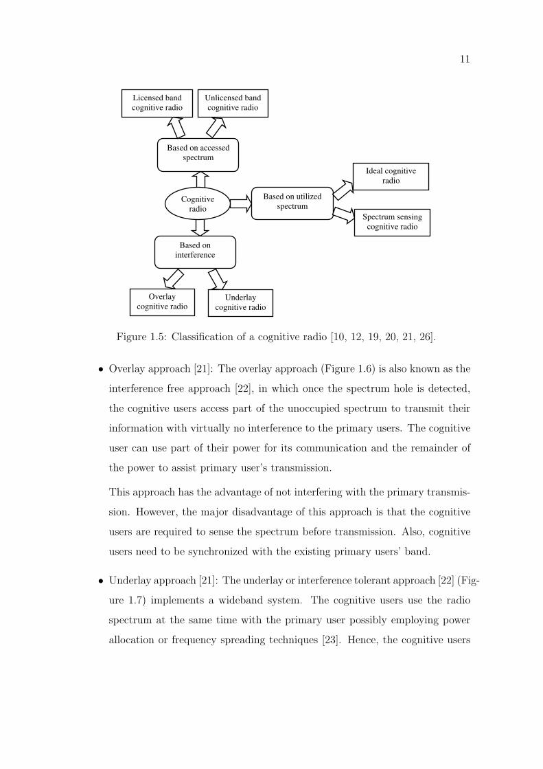
1.5 Classification of a cognitive radio [10, 12, 19, 20, 21, 26]. . . . . . . . 11
1.6 Overlay approach of cognitive radio. . . . . . . . . . . . . . . . . . . . 12
1.7 Underlay approach of cognitive radio. . . . . . . . . . . . . . . . . . . 13
1.8 Functions of a cognitive radio [7, 21, 25, 26]. . . . . . . . . . . . . . . 14
1.9 Cooperative sensing approaches. . . . . . . . . . . . . . . . . . . . . . 15
1.10 Classification of cognitive radio applications after [31]. . . . . . . . . . 17
1.11 Service reliability and coverage extension proposed by cooperative
relay network. . . . . . . . . . . . . . . . . . . . . . . . . . . . . . . . 20
2.1 Classical and cooperative models of relay networks. . . . . . . . . . . 25
2.2 Single relay network. . . . . . . . . . . . . . . . . . . . . . . . . . . . 26
2.3 Phases of transmission in cooperative relay network. . . . . . . . . . . 28
2.4 Serial topology of multiple relay network. . . . . . . . . . . . . . . . . 28
2.5 Parallel topology of multiple relay network. . . . . . . . . . . . . . . . 29
2.6 Hybrid topology of multiple relay network. . . . . . . . . . . . . . . . 29
2.7 Multiple relay network. . . . . . . . . . . . . . . . . . . . . . . . . . . 30
2.8 DF relaying scheme. . . . . . . . . . . . . . . . . . . . . . . . . . . . 31
2.9 AF relaying scheme. . . . . . . . . . . . . . . . . . . . . . . . . . . . 32
2.10 Classification of relaying schemes. . . . . . . . . . . . . . . . . . . . . 34
2.11 Diversity combining techniques. . . . . . . . . . . . . . . . . . . . . . 35
xvii
Page 18
xviii
2.12 MRC technique. . . . . . . . . . . . . . . . . . . . . . . . . . . . . . . 36
2.13 SC technique. . . . . . . . . . . . . . . . . . . . . . . . . . . . . . . . 37
3.1 Repetition-based cognitive relay network. . . . . . . . . . . . . . . . . 45
3.2 Block diagram of an energy detector. . . . . . . . . . . . . . . . . . . 46
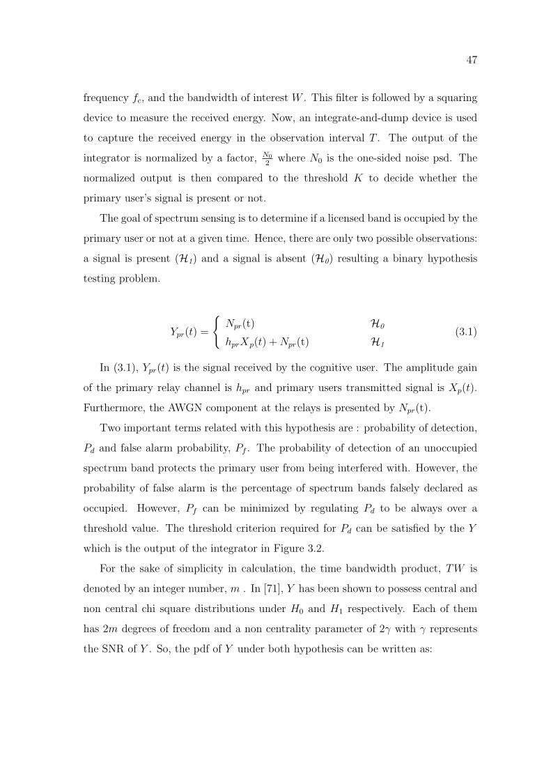
3.3 Time slots required for a cooperative relay network with M relays. . . 52
3.4 Comparison of outage probability of DF cooperative relay networks
(Cd = 1.0). . . . . . . . . . . . . . . . . . . . . . . . . . . . . . . . . . 62
3.5 Comparison of outage probability of DF cognitive relay networks
(Cd = 0.7). . . . . . . . . . . . . . . . . . . . . . . . . . . . . . . . . . 62
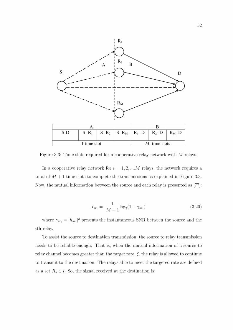
3.6 Comparison of outage probability of DF cooperative (Cd = 1.0) and
cognitive relay networks (Cd = 0.7). . . . . . . . . . . . . . . . . . . . 63
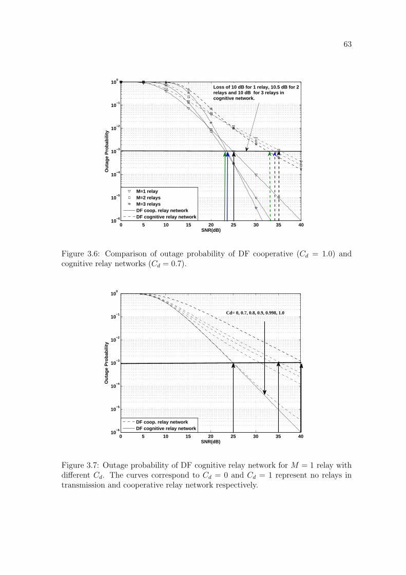
3.7 Outage probability of DF cognitive relay network for M = 1 relay
with different Cd. The curves correspond to Cd = 0 and Cd = 1
represent no relays in transmission and cooperative relay network
respectively. . . . . . . . . . . . . . . . . . . . . . . . . . . . . . . . . 63
3.8 Comparison of outage probability of AF cooperative relay networks
(Cd = 1.0). . . . . . . . . . . . . . . . . . . . . . . . . . . . . . . . . . 64
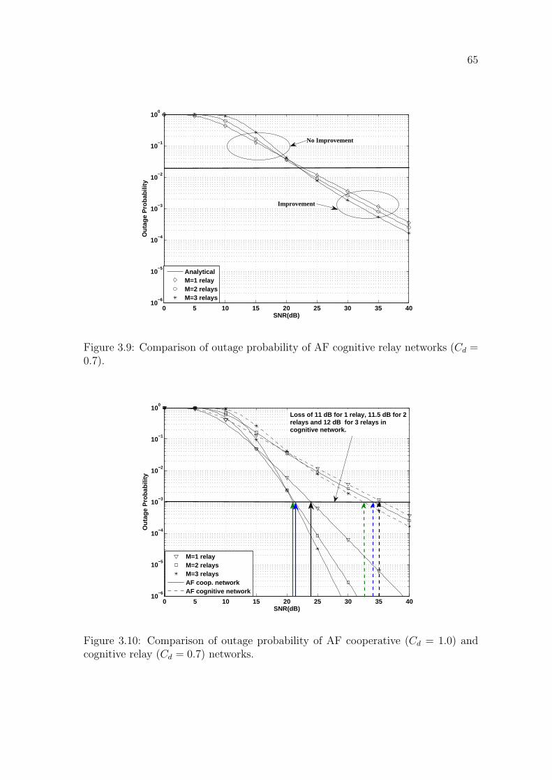
3.9 Comparison of outage probability of AF cognitive relay networks
(Cd = 0.7). . . . . . . . . . . . . . . . . . . . . . . . . . . . . . . . . . 65
3.10 Comparison of outage probability of AF cooperative (Cd = 1.0) and
cognitive relay (Cd = 0.7) networks. . . . . . . . . . . . . . . . . . . . 65
3.11 Outage probability of AF cognitive relay network for M = 1 relay
with different Cd. The curves correspond to Cd = 0 and Cd = 1
represent no relays in transmission and cooperative relay network
respectively. . . . . . . . . . . . . . . . . . . . . . . . . . . . . . . . . 66
4.1 Selection-based cognitive relay network. . . . . . . . . . . . . . . . . . 70
4.2 Comparison of outage probability between repetition and selection-
based DF cooperative relay network (Cd = 1.0). . . . . . . . . . . . . 78
4.3 Comparison of outage probability between repetition and selection-
based DF cognitive relay network (Cd = 0.7). . . . . . . . . . . . . . . 78
Page 19
xix
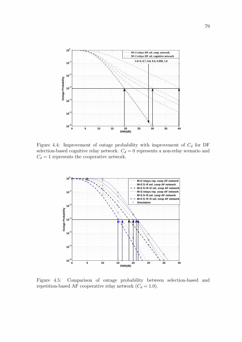
4.4 Improvement of outage probability with improvement of Cd for DF
selection-based cognitive relay network. Cd = 0 represents a non-relay
scenario and Cd = 1 represents the cooperative network. . . . . . . . 79
4.5 Comparison of outage probability between selection-based and repetition-
based AF cooperative relay network (Cd = 1.0). . . . . . . . . . . . . 79
4.6 Comparison outage probability between selection-based and repetition-
based AF cognitive relay network (Cd = 0.7). . . . . . . . . . . . . . . 80
4.7 Performance improvement of selection-based AF cognitive relay net-
work with improved Cd. Cd = 0 represents a non-relay scenario and
Cd = 1 represents the cooperative network. . . . . . . . . . . . . . . . 80
Page 20
Chapter 1
Introduction
1.1 Cognitive Radios
The wireless communications have witnessed a revolutionary rise in applications
and consumers over the past few years. The demand for inexpensive but high
speed data services, such as wireless Internet access with rich video content has
driven the wireless communications towards high quality and high speed wireless
communication services. Due to the ‘any time in any where’ flexibility of the wireless
communications, the consumer demands are growing exponentially resulting in an
increase in the demand for the radio spectrum [1].
The evolution of high quality and high speed wireless communications has ex-
panded the demands for radio spectrum at a phenomenal rate [2]. This is why most
of the frequencies have already been allocated and the bandwidth has become very
expensive. Hence, radio spectrum has become the most valuable and limited natural
resource in wireless communication. Moreover, with the emergence of a large num-
ber of new applications (a summary of the applications is presented in Table 1.1) [3],
the compelling need for wireless Internet access and high speed data network, the
demand for radio spectrum is expected to grow even more in the upcoming years.
Due to the inadequate radio spectrum and growing demands, accommodating
new applications and users in the radio spectrum band has become a challenging
problem for regulatory bodies. The reason behind this inadequacy is not only due
1
Page 21
2
Frequency bands Applications3− 30 Hz submarine communications30− 300 Hz AC power grids (50-60 Hz)300− 3000 Hz Mine communications3− 30 KHz Ultra sound applications30− 300 KHz AM radio300− 3000 KHz Aviation3− 30 MHz Short wave radio, sky wave propagation30− 300 MHz FM radio, Television broadcast300− 3000 MHz Television broadcast
3− 30 GHz Wireless networking, Satellite communications30− 300 GHz Satellite communications, Advanced weapon systems
Table 1.1: Accommodated applications in different frequency bands [3].
to the growing demand for it, but also due to the conventional spectrum allocation
methods. In the conventional spectrum allocation, the radio spectrum is divided
into channels and licensed to the telecommunication providers, Internet providers,
corporations and individuals as primary users [2]. Licensing of the radio spectrum is
done by the government regulatory bodies (i.e, Federal Communication Commission
(FCC) in the United States, Ofcom in the United Kingdom and Australian Commu-
nications and Media Authority (ACMA) in Australia and in many other countries
in a similar way), which prohibits unlicensed applications or consumers to use that
spectrum band. Figure 1.1 presents the current radio spectrum allocation chart of
Australia by ACMA updated in January, 2009. It is noticed in the Figure 1.1 that
the only two unallocated spectrum bands are found from 3 KHz to 9 KHz and from
275 GHz to 300 GHz [4]. It is anticipated that more applications and users will
demand these ‘congested’ spectrum bands. Although there are minute differences,
this scenario is more or less similar for other countries as well.
Surprisingly, practical measurements have shown that most of these licensed
channels used by the primary users do not transmit most of the time. The Figure
1.2 shows a snapshot of the utilization in the frequency band (1 MHz to 1 GHz)
Page 22
3
Figure
1.1:
Allocation
ofradio
spectrum,Australia.
Page 23
4
Figure 1.2: Utilization of radio spectrum in Melbourne, Australia.
measured at the Victoria University in Melbourne, Australia. The measurement in
Figure 1.2 shows that most of the frequency band remained unutilized (in blue) at
the time of observation.
This underutilization, coupled with high demand from other potential users,
is creating an insufficient use of the available radio spectrum [5]. Reducing the
width of the spectrum guard band to minimum can be a rudimentary solution to
vacate new spaces in the spectrum band for primary users. A guard band is an
unused band between the radio spectrum bands to avoid interference in conventional
spectrum allocation. The minimum width of the guard band should guarantee the
least interference to the radio spectrum bands. Hence, there is an upper limit
of users that can be fitted into a given guard bandwidth. In the Figure 1.3, a new
primary user has been accommodated by reducing the guard band. The propagation
characteristics also determine the finite frequencies in the radio spectrum bands that
can be allocated to a specific application and user.
Also, many more radio spectrum users could be accommodated if the unutilized
radio spectra (i.e, in 300-500 MHz and 600-900 MHz in Figure 1.2) licensed to
the primary user were utilized under spatio/temporal opportunities [6]. Such a
wireless technology named ‘cognitive radio’ has been recently proposed by Mitola [7].
Page 24
5
(a) Sparse spectrum allocation
Reduced guard band
(b) Compact spectrum allocation
Guard band Primary user
Figure 1.3: Guard band utilization to accommodate new applications and users.
‘Cognitive radio’ is a wireless technology that can be employed to sense, recognize
and utilize the unutilized radio spectrum wisely at a given time [8]. The main
characteristic of a cognitive radio is its inherent intelligence that allows sensing all
possible radio spectra before it makes an intelligent decision on how and when to
make use of a particular sector of the spectrum for communications. The additional
radio spectra users are named as cognitive users [9].
A discussion on cognitive radio and FCC’s initiatives and efforts to promote it for
wireless communication applications will be presented in the following subsections.
Also, a broad classification, characteristics and functions of cognitive radio will be
discussed.
1.1.1 Background on Cognitive Radio
Cellular systems, wireless local area systems, satellite systems, paging systems, blue-
tooth, ultra wideband systems, ZigBee systems and many more wireless applications
have initiated an exponential growth in wireless communications. The multi-media
based applications introduced by the Internet and the world wide web (WWW) have
made wireless communications extensively popular. At present, wireless communi-
cation is moving forward to the fourth generation (4G, is also popularly known as the
Page 25
6
Parameter 3G 4GFrequency bands 1.8− 2.5 GHz 2− 8 GHz
Data rate Up to 2 Mbps (384 kbps deployed) Up to 100 MbpsTechnologies CDMA OFDMA(uplink) and SC-
FDMA(downlink)Network capacity Less number of simultaneous users Higher number of simulta-
neous usersRadio interfaces Fixed radio interfaces Adaptive radio interfaces
Table 1.2: A comparison between 3G and 4G wireless communication.
next generation). These 4G systems are expected to replace the existing third gen-
eration (3G) wireless communications and will provide complete and secure voice,
data and streamed multi-media applications.
The Table 1.2 presents a comparison between 3G and 4G wireless communica-
tion in terms of frequency bands, data rate, available technologies etc. The table
shows the expected frequency bands and data rate for the 4G wireless communica-
tion is much higher than the 3G wireless communication [3]. Providing the required
frequency bands and data rate to the 4G wireless communication has become chal-
lenging due to the adopted conventional spectrum allocation methods. The dictated
government policies on the licensed spectrum bands makes the task even more com-
plicated. However, the scarcity of the radio spectrum has been found artificial
because practical measurements have shown that the spectrum remains unutilized
at most times. Hence, to optimize the demand for the radio spectrum and utilize
the unutilized licensed spectrum, cognitive radio was proposed by Mitola [10].
Mitola’s definition of cognitive radio is [10]:
“The term cognitive radio identifies the point at which wireless personal digital
assistants (PDAs) and the related networks are sufficiently computationally intelli-
gent about radio resources and related computer-to-computer communications to:
• (a) detect user communications needs as a function of use context, and
Page 26
7
Transmitted
Radio Spectrum
(Outside world)
Channel state estimation and
predictive modeling
Radio-scene analysis
RF stimulisignal
Quantized channel capacity
Transmit power control and
spectrum management
Spectrum
holes,
Noise
floor,
traffic
statistics
Figure 1.4: Haykin’s model of a cognitive radio.
• (b) to provide radio resources and wireless services most appropriate to those
needs.”
This definition of cognitive radio considers a high level of awareness to employ
intelligence in the choice of the radio spectrum band, air interface, or protocol to
higher-level tasks of planning, learning, and evolving new upper layer protocols [8].
Later, Haykin in [9] described the cognitive radio as an intelligent wireless com-
munication system that is aware of its surrounding environment. He also mentioned
two primary objectives of cognitive radio, namely:
• highly reliable in communication wherever and whenever needed.
• efficient in utilizing the radio spectrum.
The basic model of cognitive radio as described in [9] is presented in Figure 1.4.
In this model, the cognitive radio:
• observes the radio environment (i.e., outside world) on a continuous time basis
to analyse the environment by empowering all users’ receivers.
Page 27
8
• learns from the environment and adapts the performance of each transceiver
to statistical variations in the incoming radio frequency (RF) stimuli.
• estimates the channel and predicts the network model to facilitate the trans-
mission.
• controls the transmit power and manages the spectrum (i.e, through spectrum
hole detection) and allocates allows the transmission.
Another popular definition of cognitive radio from FCC is [11]:
“A cognitive radio is a radio that can change its transmitter parameters (i.e,
transmit power) based on interaction with the environment in which it operates.”
The cognitive radio also allows the cognitive users to share the spectrum on an
opportunistic basis. So, in 2004 FCC defined the cognitive radio as a device that can
borrow the licensed spectrum when required without generating harmful interference
to the licensed users [12].
All the above definitions of cognitive radio share three major common points:
• Sensing for available unoccupied primary spectrum bands intelligently.
• Allowing the cognitive users to use those bands efficiently.
• Causing no/minimum interference to the primary user.
Hence, a cognitive radio intelligently learns the environment to sense the available
unoccupied radio spectrum bands, adapts the environment to allow transmission and
does not create harmful interference to the primary users.
The research on cognitive radio is still in its infancy. But, it has attracted
significant interest of both academia and industry since it has been introduced in
1999 [13]. This can be observed from the increasing number of publications, IEEE
conferences specially on the cognitive radio (i.e, DySPAN, CROWNCOM), number
of special issues of journals and etc.
Page 28
9
In 2002, FCC’s spectrum policy report on licensed spectrum utilization triggered
the following questions:
• (i) how to open up the unutilized spectrum?
• (ii) should the spectrum be licensed or unlicensed?
In the same year, FCC stated in a notice of inquiry (NOI) named ‘Additional
spectrum for unlicensed devices below 900 MHz and in the 3 GHz’ [14, 15] that an
unlicensed device can only transmit if it can identify an unutilized frequency band.
This NOI also considered the possibility of sharing TV bands with the unlicensed
users.
In 2003, FCC introduced an interference temperature model in another NOI and
in a notice of proposed rule making (NPRM) named ‘Establishment of an interfer-
ence temperature metric’. Interference temperature metric quantifies and manages
the upper bound of the interference caused to the primary users by the unlicensed
devices [16]. FCC issued another NPRM named ‘Facilitating opportunities for flexi-
ble, efficient and reliable spectrum use employing cognitive radio technologies’ in the
same year in which FCC intended to promote an advanced technology for wireless
communication. The cognitive radio offered to be that possible advanced technology
by providing a more intelligent system for allocating spectrum that can dramatically
increase the amount of available spectrum. In this NPRM FCC proposed that TV
channels 5−13 in the VHF band and 14−51 in the UHF band could be used for
fixed broadband access systems.
The standardization of the cognitive radio was carried by the IEEE in parallel
with the FCC. Sevension in 2004 prepared a document named ‘In reply to comments
of IEEE 802.18’ which indicated that IEEE 802.18 supports the opportunistic use
of the licensed spectrum bands on a non-interfering basis [17]. Recently Carl. R.
Sevension overviewed the newly developed IEEE 802.22 (wireless regional area net-
works) WRAN standard [18]. IEEE 802.22 WRANs are designed to operate in the
TV broadcast bands while ensuring that no harmful interference is caused to the
Page 29
10
incumbent operation (i.e., digital TV and analog TV broadcasting) and low-power
licensed devices such as wireless microphones.
1.1.2 Classifications and Characteristics
The cognitive radio can be classified based on different parameters (part of spectrum
band in use, interference etc). The chart in Figure 1.5 presents a summary of the
classifications of cognitive radio. Depending on the utilization of the spectrum band,
the cognitive radio can be broadly classified as:
• Ideal cognitive radio: The ideal cognitive radio [10] is considered as a ‘genie’.
It knows the operating parameters of all radios in its environment and can
make a fully informed decision on how to make the best use of any unutilized
spectrum bands. This is a hypothetical scenario but it helps in understanding
the theme and operation of cognitive radio.
• Spectrum sensing cognitive radio: Spectrum sensing cognitive radio is a special
case of the ideal cognitive radio. Such a cognitive radio just observes primary
spectrum bands before the transmission [12]. Spectrum sensing cognitive radio
seems to be more realistic than ideal cognitive radio.
Based on the parts of the spectrum available for access, the cognitive radio
system can be divided into:
• Licensed band cognitive radio: A cognitive radio system capable of using the
spectrum bands assigned to the licensed users is called a licensed band cogni-
tive radio system [19].
• Unlicensed band cognitive radio: An unlicensed cognitive radio is allowed to
use only the unlicensed part of the spectrum bands [20].
Depending on overlay or underlay approach employed during transmission cog-
nitive radio can be classified as:
Page 30
11
Spectrum sensing
cognitive radio
Ideal cognitive
radio
Based on utilized
spectrumCognitive
radio
Unlicensed band
cognitive radio
Licensed band
cognitive radio
Underlay
cognitive radio
Overlay
cognitive radio
Based on
interference
Based on accessed
spectrum
Figure 1.5: Classification of a cognitive radio [10, 12, 19, 20, 21, 26].
• Overlay approach [21]: The overlay approach (Figure 1.6) is also known as the
interference free approach [22], in which once the spectrum hole is detected,
the cognitive users access part of the unoccupied spectrum to transmit their
information with virtually no interference to the primary users. The cognitive
user can use part of their power for its communication and the remainder of
the power to assist primary user’s transmission.
This approach has the advantage of not interfering with the primary transmis-
sion. However, the major disadvantage of this approach is that the cognitive
users are required to sense the spectrum before transmission. Also, cognitive
users need to be synchronized with the existing primary users’ band.
• Underlay approach [21]: The underlay or interference tolerant approach [22] (Fig-
ure 1.7) implements a wideband system. The cognitive users use the radio
spectrum at the same time with the primary user possibly employing power
allocation or frequency spreading techniques [23]. Hence, the cognitive users
Page 31
12
Power density
Primary Users Cognitive Users
Frequency
Figure 1.6: Overlay approach of cognitive radio.
must transmit with low transmit power to operate below the noise floor of the
primary users ensuring a tolerable interference to the primary users.
Underlay approach enjoys the flexibility of transmission at any time and doesn’t
need to be synchronized with the primary users’ band. However, the interfer-
ence power constraints associated with this approach allow only short range
communications.
A cognitive radio has the following characteristics which distinguishes it from
other wireless communication technologies :
• Flexibility: The ability to change the waveform and configuration of a de-
vice [9] is known as flexibility. For an example, a cell tower may operate in
the cell band for telephony purposes, but it may change its waveform to get
the telemetry during the off-peak. Hence, the same band is flexible enough to
be used in two different roles.
• Agility: Agility is the ability of changing the spectrum band in which a device
will operate [12]. In the global system for mobile (GSM) communications,
mobile phones show their agility in the GSM spectrum bands by operating in
two or more bands (i.e, 900 MHz, 1700 MHz and 1900 MHz).
Page 32
13
Power density
Primary Users Cognitive User
Noise floor
Frequency
Figure 1.7: Underlay approach of cognitive radio.
Flexibility and agility together characterize the cognitive radio to be ‘adaptive’.
This means the cognitive radio can use different waveforms in different bands.
• Perceiving: The ability to observe the state of the existing system includ-
ing the spectrum bands and the environment [5, 9, 24] makes cognitive radio
perceiving. Thus, it allows dynamics in the cognitive radio.
• Networking: Networking is the ability of communicating among multiple cog-
nitive nodes [2]. Thus, it allows the combined sensing and controlling capacity
of those nodes. The wireless networking allows the interaction among the
group of cognitive radios. These interactions can be useful for sensing an
unused spectrum band.
The cognitive radio allows the implementation of the above mentioned char-
acteristics in an environment through the following functions (presented in Fig-
ure 1.8 [25, 26]):
• Spectrum sensing: The fundamental challenge of the cognitive radio is to sense
the presence/absence of spectrum holes efficiently [21]. Spectrum sensing can
be further divided into the following three categories:
Page 33
14
Functions of a
cognitive radio Spectrum
management
Spectrum sharing
Spectrum sensing Cooperative
sensingInterference based
detection
Primary signal
sensing
Cyclostationary
feature detection
Energy detection Matched filter
detection
Spectrum Mobility
Figure 1.8: Functions of a cognitive radio [7, 21, 25, 26].
– Primary signal sensing: A cognitive radio may use any of the following
approaches to sense the primary user’s signal:
∗ Energy detection [27].
∗ Matched filter detection [28].
∗ Cyclostationary feature detection [29].
– Cooperative sensing: Multiple cognitive users may sense the spectrum
hole cooperatively by exchanging their information [28, 30]. Cooperative
sensing may use any of the following approaches to sense the spectrum
hole:
∗ Figure 1.9 (a) presents cooperative sensing employing a relay to assist
the source-to-destination transmission when the source-to-destination
link is under fading/shadowing effects.
∗ A number of relays in the neighbourhood of the transmitting relay
Page 34
15
S
R
D
R
S D
Neighborhood relays
(b) Cooperative transmission
employing neighbor relays.
(a) Cooperative transmission when
source-to-destination link is in fade.
Figure 1.9: Cooperative sensing approaches.
presented in the Figure 1.9 (b) can sense the spectrum cooperatively
for its transmission.
– Interference based detection: Only those spectrum bands are sensed
which will create no or minimum interference to the primary user, if
they are accessed [26].
• Spectrum management: If more than one spectrum hole is detected in the
desired frequency band, the cognitive radio analyses the available radio spec-
trum bands. Then, it chooses the best frequency among the spectrum bands
to ensure the quality of service according to the user’s requirements.
• Spectrum mobility: The process of changing of the operational frequency of
cognitive radio is called spectrum mobility [7]. Mobility enables the cognitive
radio to use the spectrum bands in a dynamic manner by allowing the use of
the best available frequency band.
• Spectrum sharing: As the spectrum hole is detected, cognitive radio can share
the part of the spectrum bands to transmit its own information. Cognitive
radio allows spectrum sharing employing overlay or underlay approach. A
dynamic spectrum sharing is employed through the spectrum mobility.
Page 35
16
1.1.3 Application Areas
A major driving force of any technology is to meet end users’ demands. A chart
in Figure 1.10 summarizes the broad classifications of cognitive radio applications.
The application of cognitive radio can be broadly classified into the following two
groups [31]:
• Existing applications where cognitive radio can offer partial or full improve-
ment in the performance.
• New applications where cognitive radio can be beneficial.
Both of the groups may further be classified into four areas of cognitive radio
applications as follows :
• Wireless resource optimization applications.
• Communication quality enhancing applications.
• Interoperability enabling applications.
• Service specific applications.
Resource optimization and quality enhancement of wireless applications can be
discussed together. Based on the network demands and applications, the cogni-
tive radio can intelligently decide to adapt the more appropriate network protocol.
Hence, it optimizes the network resources. While deciding the network protocol,
the cognitive radio also reconfigures the network in terms of network capacity to
improve the quality of service (QoS) [31].
Interoperability [31] enables the intelligence into the wireless communication
applications. An immediate application of the cognitive radio interoperability can
be found in military applications. In other application areas, such as in consumer
applications, cognitive radio can offer interoperability to the licensed, unlicensed,
and semi-licensed spectrum [32] services over diverse networks.
Page 36
17
Existing
wireless
applications
improved by
cognitive
radio
Wireless
resource
optimization
applications
Communication
quality
enhancing
applications
Service specific
applications
Interoperability
enabling
applications
New cognitive
radio
applications
Cognitive
radio
applications
Figure 1.10: Classification of cognitive radio applications after [31].
The service specific applications of cognitive radio technology may include the
mobile phones, laptop and fax machine etc [31]. The cognitive radio can help in
establishment of a remote home office. This may be helpful in reducing traffic on
roads during office hours, office resources and international travel expenses through
remote conferencing. The cognitive radio may identify the unutilized spectrum
bands from distant places to avoid the congestion of the wireless network at high
traffic hours [31]. Cognitive radio can be helpful in realization of the emerging
femtocell technology. Femtocell technology can be deployed through cognitive radio
to provide a low-cost, low-power (underlay approach) medium of network coverage
extension. The cognitive radio can also be implemented in bio-medical applications,
traffic controlling, weather fore-casting and many other service specific applications.
The IEEE 802.22 standard [18] has proposed the employment of cognitive radio in
bringing broadband access to rural areas.
Page 37
18
1.2 Challenges of Cognitive Radio
The main two challenges to the success of cognitive radio include the primary user
detection and the transmission opportunity exploitation [33]. Detection of a primary
user actually leads to the detection of a spectrum hole. A spectrum hole is an
unoccupied spectrum band which is licensed to the primary user. In the literature,
spectrum hole detection is known as the ‘spectrum sensing’. The cognitive users
can exploit the opportunity of transmission to improve their performance through
either overlay approach or underlay approach.
Regardless of the approach employed by the cognitive radio, the inherited fading
phenomena of the wireless channels [34], limits the service reliability and coverage
of the wireless communication services.
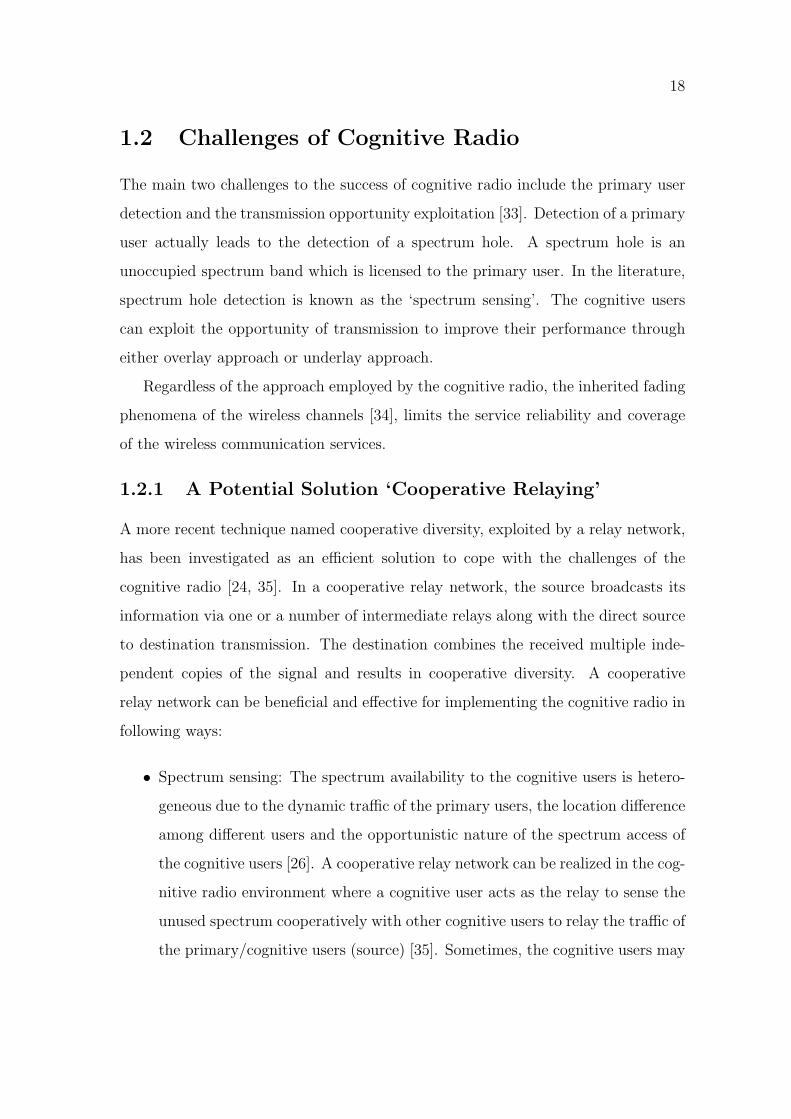
1.2.1 A Potential Solution ‘Cooperative Relaying’
A more recent technique named cooperative diversity, exploited by a relay network,
has been investigated as an efficient solution to cope with the challenges of the
cognitive radio [24, 35]. In a cooperative relay network, the source broadcasts its
information via one or a number of intermediate relays along with the direct source
to destination transmission. The destination combines the received multiple inde-
pendent copies of the signal and results in cooperative diversity. A cooperative
relay network can be beneficial and effective for implementing the cognitive radio in
following ways:
• Spectrum sensing: The spectrum availability to the cognitive users is hetero-
geneous due to the dynamic traffic of the primary users, the location difference
among different users and the opportunistic nature of the spectrum access of
the cognitive users [26]. A cooperative relay network can be realized in the cog-
nitive radio environment where a cognitive user acts as the relay to sense the
unused spectrum cooperatively with other cognitive users to relay the traffic of
the primary/cognitive users (source) [35]. Sometimes, the cognitive users may
Page 38
19
not use their entire available spectrum due to the low traffic demand. In this
case, one cognitive user may act as the relay to other cognitive users (source)
to assist their transmission.
In both cases, the cooperative relay network increases the probability of de-
tecting an unused spectrum band for the cognitive users resulting in an im-
provement in service reliability and coverage extension. Hence, a cooperative
relay network can be helpful in spectrum sensing both for the primary users
and cognitive users.
• Interference tolerance: The cooperative relay network employs the coopera-
tive diversity to combat with the interference [25]. The source can also choose
an appropriate relay route to transmit avoiding the interference (overlay ap-
proach) or causing the minimum interference (underlay approach) in the cog-
nitive environment. Thus, cognitive users can assure no/minimum interference
to the primary user [5].
• Reliability of service: A cooperative relay network can be extremely effective
to cope with the fading phenomena of the wireless communications through
the cooperative diversity [36]. It also increases the reliability of the service by
guaranteeing the transmission even if the source to destination link is under
fade. So, the cognitive users can guarantee the transmission under a fading
environment.
• Extension of coverage: The cooperative relay network also expands the net-
work coverage by increasing the source to destination travelling distance for
the transmitted signal. This way, the cognitive users become more suitable for
a long range transmission.
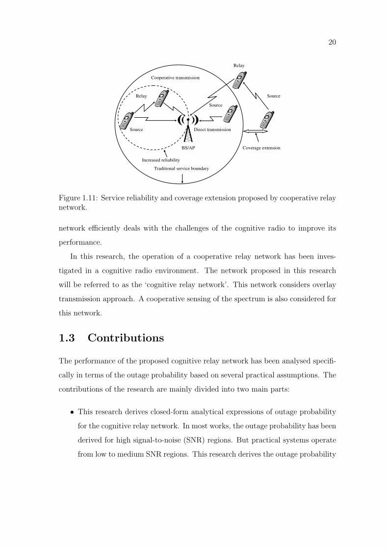
A cooperative relay network depicted in Figure 1.11 shows the increase in the
service reliability and expansion of network coverage. Thus, the cooperative relay
Page 39
20
Relay
Source
Cooperative transmission
BS/AP
Direct transmission
Source
Relay
BS/AP
Cooperative transmission
Increased reliability
Traditional service boundary
Direct transmission
Relay
Source
Source
Source
Coverage extension
Figure 1.11: Service reliability and coverage extension proposed by cooperative relaynetwork.
network efficiently deals with the challenges of the cognitive radio to improve its
performance.
In this research, the operation of a cooperative relay network has been inves-
tigated in a cognitive radio environment. The network proposed in this research
will be referred to as the ‘cognitive relay network’. This network considers overlay
transmission approach. A cooperative sensing of the spectrum is also considered for
this network.
1.3 Contributions
The performance of the proposed cognitive relay network has been analysed specifi-
cally in terms of the outage probability based on several practical assumptions. The
contributions of the research are mainly divided into two main parts:
• This research derives closed-form analytical expressions of outage probability
for the cognitive relay network. In most works, the outage probability has been
derived for high signal-to-noise (SNR) regions. But practical systems operate
from low to medium SNR regions. This research derives the outage probability
Page 40
21
that is valid for any arbitrary SNR region. At first, repetition-based decode-
and-forward (DF) and amplify-and-forward (AF) cognitive relay networks have
been investigated for outage probability evaluation. Repetition-based proto-
cols inherit the problem of bandwidth expansion which can be avoided by
selection-based protocols (i.e, the relay with the best transmission channel).
Closed-form outage probability expressions of selection-based networks have
also been derived for DF and AF relaying schemes and compared with those
of the repetition-based networks.
Analytical results are validated through the simulations. It has been observed
that for DF relaying protocol the analytical and simulation results match ex-
actly for both repetition-based schemes and selection cooperation. The channel
end-to-end SNR for AF relaying scheme is difficult to track mathematically.
Hence, an approximate yet accurate approach has been considered to analyse
the network. So, the analytical results are lower bounds at the low SNR re-
gions (0− 10 dB) and match exactly for medium to higher SNR regions with
the simulation results for both repetition-based and selection cooperation AF
relaying protocol. However, the analyses presented in this work provide tight
bounds.
The proposed cognitive relay network shows improved performance in terms of
outage probability over the traditional cognitive radio. It has been observed
that the network performance does not always improve with the increasing
number of relays for the repetition-based networks. This is due to the need
of additional time slots for the time division operation in the repetition-based
networks. A further enhancement in the performance is found for selection-
based networks over repetition-based networks due to the bandwidth advan-
tage. The increased number of relays always improves the performance of a
selection-based network. However, the network performance degrades more in
Page 41
22
selection-based networks than the repetition-based networks when the spec-
trum is unavailable.
• The cognitive relay considered in this thesis borrows the spectrum from the
primary user opportunistically to transmit its information. Hence, the spec-
trum may always not be available to the cognitive relays. Unavailability of the
spectrum degrades the network performance. This thesis analyses the outage
probability of a conventional cooperative relay network to set the benchmark
performance for comparison with that of the cognitive relay network. An im-
provement in performance is shown by employing the cooperative sensing [2]
through the relays when the spectrum is not available.
1.4 Structure of the Thesis
This thesis is organized as follows:
• Chapter 2 introduces the preliminary concepts of the cooperative relay net-
work and cognitive relay network considered in this thesis. It summarizes the
existing state of the art work in these areas to provide the background required
to understand the rest of the thesis.
• Chapter 3 presents the proposed system models for the DF and AF cogni-
tive relay network with repetition-based protocols. The spectrum acquisition
model and cooperative spectrum sensing have been discussed. Statistical anal-
ysis has been presented to evaluate the outage probability.
• Chapter 4 explains the selection criteria for relays in the cognitive relay net-
work. The closed-form expressions of the outage probability have been derived
to evaluate network performance for both DF and AF relaying schemes. The
analytical results have been validated through the simulation results. Also,
the outage probability expressions of the selection-based networks have been
Page 42
23
compared to that of repetition-based networks for both DF and AF relaying
schemes.
• Chapter 5 concludes this thesis and suggests future possible research directions.
Page 43
Chapter 2
Background and Literature Survey
This chapter presents the preliminaries and background of the cooperative relay
network. Furthermore, it describes the cognitive relay network considered in the
rest of the thesis. The statistics required to calculate the outage probability of the
proposed network have also been discussed in this chapter.
2.1 Cooperative Relay Network
The main goal of the wireless communications has now become to achieve higher
data rates with a larger coverage in transmission as the wireless communications
approach to the 4G. The conventional peer-to-peer communications suffer from fad-
ing and attenuation adversely [34]. Fading/shadowing effect and attenuation in the
wireless network limit the transmission rate and coverage. The solution to these
shortcomings is the cooperative diversity which can be realized by the cooperative
relay communication. This section reviews the background of the cooperative relay
network. Network models, relaying schemes and the combining techniques for the
cooperative relay network are also discussed.
The cooperative relay network transmits an independent copy of the same signal
via a relay to the destination along with the direct source-destination link. In this
thesis, the terms ‘direct link transmission’ and ‘source-to-detination transmission’
have been used simultaneously implying the same meaning. Multiple relays can be
also be employed to transmit multiple independent copies. Hence, for a cooperative
24
Page 44
25
RelayRelay
DestinationSourceDestination
Source
Cooperative relay network Classical relay network
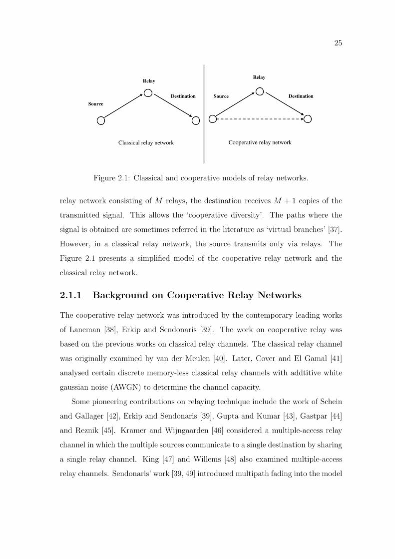
Figure 2.1: Classical and cooperative models of relay networks.
relay network consisting of M relays, the destination receives M + 1 copies of the
transmitted signal. This allows the ‘cooperative diversity’. The paths where the
signal is obtained are sometimes referred in the literature as ‘virtual branches’ [37].
However, in a classical relay network, the source transmits only via relays. The
Figure 2.1 presents a simplified model of the cooperative relay network and the
classical relay network.
2.1.1 Background on Cooperative Relay Networks
The cooperative relay network was introduced by the contemporary leading works
of Laneman [38], Erkip and Sendonaris [39]. The work on cooperative relay was
based on the previous works on classical relay channels. The classical relay channel
was originally examined by van der Meulen [40]. Later, Cover and El Gamal [41]
analysed certain discrete memory-less classical relay channels with addtitive white
gaussian noise (AWGN) to determine the channel capacity.
Some pioneering contributions on relaying technique include the work of Schein
and Gallager [42], Erkip and Sendonaris [39], Gupta and Kumar [43], Gastpar [44]
and Reznik [45]. Kramer and Wijngaarden [46] considered a multiple-access relay
channel in which the multiple sources communicate to a single destination by sharing
a single relay channel. King [47] and Willems [48] also examined multiple-access
relay channels. Sendonaris’ work [39, 49] introduced multipath fading into the model
Page 45
26
R
sdh
srh rdh
DS
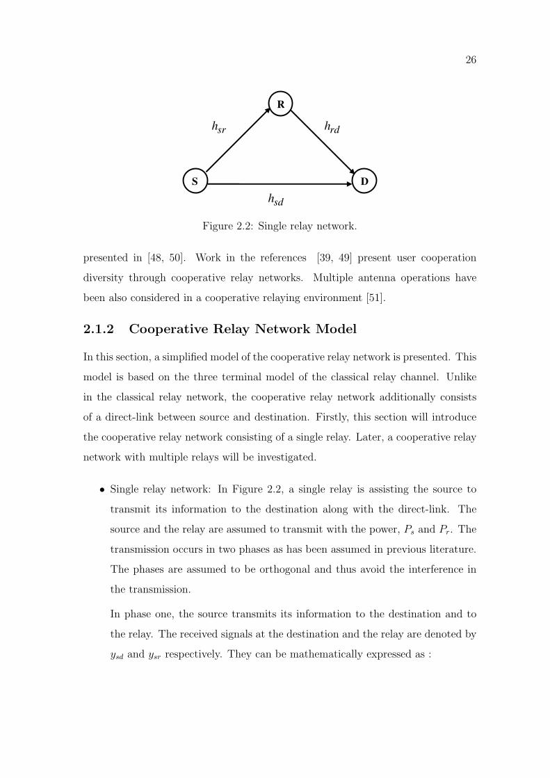
Figure 2.2: Single relay network.
presented in [48, 50]. Work in the references [39, 49] present user cooperation
diversity through cooperative relay networks. Multiple antenna operations have
been also considered in a cooperative relaying environment [51].
2.1.2 Cooperative Relay Network Model
In this section, a simplified model of the cooperative relay network is presented. This
model is based on the three terminal model of the classical relay channel. Unlike
in the classical relay network, the cooperative relay network additionally consists
of a direct-link between source and destination. Firstly, this section will introduce
the cooperative relay network consisting of a single relay. Later, a cooperative relay
network with multiple relays will be investigated.
• Single relay network: In Figure 2.2, a single relay is assisting the source to
transmit its information to the destination along with the direct-link. The
source and the relay are assumed to transmit with the power, Ps and Pr. The
transmission occurs in two phases as has been assumed in previous literature.
The phases are assumed to be orthogonal and thus avoid the interference in
the transmission.
In phase one, the source transmits its information to the destination and to
the relay. The received signals at the destination and the relay are denoted by
ysd and ysr respectively. They can be mathematically expressed as :
Page 46
27
ysd =√Pshsdx+ nsd (2.1)
ysr =√Pshsrx+ nsr (2.2)
In (2.1) and (2.2), x is the transmitted symbol drawn out of a modulation
scheme such as BPSK, QPSK or MQAM. The average energy of the symbols
has been normalized to E[|x|2]= 1. The channel coefficients from source-
to-destination, source-to-relay are denoted by hsd and hsr respectively. The
channel coefficients have been modelled as complex Gaussian random variables
(RVs) with zero-mean and variances λsd and λsr respectively leading to the
well known flat Rayleigh fading channel. The AWGN noise at the source,
relays and the destination are given by nsd and nsr respectively. The noise
terms are modelled as complex Gaussian RVs with zero-mean and single sided
power spectral density (psd) N0.
In the phase two, the relay processes the signal and forwards to the destination.
The received signal at the destination is yrd and can be expressed as:
yrd =√PrhrdZ(ysr) + nrd (2.3)
In (2.3), relay-to-destination channel coefficients are denoted by hrd. The
channel coefficient has been modelled as complex Gaussian random variable
(RV) with zero-mean and variance λrd. The AWGN noise at the destination
is nrd.
In (2.3), Z(·) depends on the cooperative relaying scheme implemented at the
relay. The operation of Z(·) related to different cooperative relaying schemes
will be discussed in more detail later. In phase two, M number of time slots
are required to guarantee the orthogonal transmission and the time division
multiple access (TDMA) [38]. The relays can not transmit and receive signals
Page 47
28
S
R
D
(a) Phase-I. (b) Phase-II.
R
S D
Figure 2.3: Phases of transmission in cooperative relay network.
S R R R R R D
Figure 2.4: Serial topology of multiple relay network.
simultaneously because of the half-duplex constraint normally assumed in the
literature. Half-duplex systems provide two ways for communications but only
one way at a time. Hence, the relays just receive the signal from the source in
the first phase. In the second phase, only when the source stops transmission,
relays transmit the received signal to the destination. Simultaneous transmis-
sion to the destination can be employed through frequency division multiple
access at the cost of some bandwidth expansion.
• Multiple relay network: A multiple cooperative relay network may have the
following topologies:
– Serial topology [52]: In a serial topology of the multiple cooperative relay
network relays are connected in series with each other as presented in
Figure 2.4.
– Parallel topology [52]: The cooperative relay network with parallel topol-
ogy consists of parallel relay paths as in Figure 2.5.
Page 48
29
S
R
R
D
Figure 2.5: Parallel topology of multiple relay network.
R
S
R
D
R R
Figure 2.6: Hybrid topology of multiple relay network.
– Hybrid topology [52]: In this topology, the cooperative relay network
consists of both serial and parallel relay paths as presented in Figure 2.6.
This thesis considers parallel cooperative relay network (presented in Figure
2.7), in which the source transmits its information to the destination via M
number of relays, Ri, i = 1, 2, ....M and through the direct-link in the first
phase. The received signals at the destination and the i −th relay are denoted
by ysd and ysri respectively. In the second phase, the relays process the received
signal from the source and transmit towards the destination. Now, (2.1), (2.2)
and (2.3) can be modified for a multiple relay cooperative network as:
ysd =√Pshsdx+ nsd (2.4)
Page 49
30
R
1hsr
2hsr
Mhsr
1hrd
2hrd
hsd
R
R
.
.
Mhrd
DS
Figure 2.7: Multiple relay network.
ysri =√
Pshsrix+ nsri (2.5)
yrdi =√
PrihridZ(ysri) + nrid (2.6)
The symbols used in (2.4), (2.5) and (2.6) bear the same meaning as in
(2.1), (2.2) and (2.3) for i = 1, 2, ....M .
2.1.3 Cooperative Relaying Schemes
Cooperative relaying schemes are generally categorized as follows and presented in
Figure 2.10:
• Fixed cooperative relaying schemes: In fixed cooperative relaying schemes, the
channel resources are divided in a fixed (deterministic) manner between the
source and the relay. Based on the relaying scheme applied, the processing at
the relay (i.e, the operation of Z(·)) becomes different. Two widely used fixed
relaying schemes are [38]:
– DF relaying scheme : In a DF relaying scheme (also known as regenerative
relaying), the relay decodes the received signal from the source, re-encodes
Page 50
31
R
DS
Figure 2.8: DF relaying scheme.
it and then retransmits to the destination. If the decoded signal at the
relay is presented as x̂, then the transmitted signal from the relay can
be presented as√Prx̂ [53]. There is a possibility that the relay decodes
the signal incorrectly and forwards it resulting in an error propagation.
Hence, the decoding at the relay becomes meaningless. For such a scheme,
the diversity achieved is one, because the network performance is limited
by the worst link from source-to-relay and from source-to-destination.
Error correction codes are one way to reduce error in the decoded signals.
Laneman [38] proposed that if the SNR of the received signal at the relay
exceeds a certain threshold, only then the relay will decode and forward
the information to the destination. This constraint reduces incorrect
decoding at the relay.
The principal advantage of the DF relaying scheme is not having any am-
plified noise in the transmitted signal to the destination. The drawbacks
of the DF relaying scheme are error propagation at the relay due to the
possibility of incorrect decoding of the coded signals and high computa-
tion load on the relay nodes.
– AF relaying scheme: For the AF relaying scheme (also known as non-
regenerative relaying), the relay scales the revived signal from the source
and transmits an amplified version of the signal to the destination. The
Page 51
32
S
R
D
Figure 2.9: AF relaying scheme.
amplification is done basically to combat the effect of the fading between
the source to relay channel. The relay performs amplification by scaling
the revived signal by a factor that is inversely proportional to the received
power. The AF relaying can be further divided into:
∗ Channel state information (CSI) assisted AF relaying [54]: In the
CSI-assisted relaying, the relay employs instantaneous CSI of the
source to the relay link to control the gain obtained at relay. Hence,
it scales the power of the retransmitted signal. The scaling at the re-
lay is also known as the instantaneous power scaling or variable gain
scaling. Hence, the instantaneous transmitted power is always nor-
malized. The amplification factor for the cooperative relay network
described by (2.1), (2.2) and (2.3) can be expressed as-
G =
√Pr
(Ps|hsr|2 +N0)(2.7)
∗ Fixed gain relaying [54]: In the blind relaying, relay do not need
instantaneous CSI of the the source to relay link at the relay, but
scale the the signal with a fixed gain. Hence, this results in variable
power at the retransmitted signal and the average transmitted power
Page 52
33
is normalized. This scaling is also known as the average power scal-
ing or fixed gain scaling. For a cooperative relay network described
by (2.1), (2.2) and ( 2.3), the amplification factor is:
G =
√Pr
E[|ysr|2
]+N0
(2.8)
where E(·) is the expectation operator.
The AF relaying scheme has advantages of simple implementation and
low computation load for the relay nodes. The main drawback of the
AF protocol is that it amplifies the noise in the signal leading to some
performance degradation [53].
All fixed relaying schemes inherit the advantage of easy implementation. How-
ever, they suffer from the bandwidth efficiency. This problem can be avoided
by using the adaptive relaying schemes. In Figure 2.10, the classification of
cooperative relaying schemes has been summarized.
• Adaptive cooperative relaying [38]: As the name implies, adaptive relaying will
have channel resources allocated in an adaptive manner. Two major adaptive
relaying are [38]: Selection relaying and Incremental relaying.
– Selection relaying: In the selection relaying [55, 56], the relay node with
the highest relay-to-destination channel gain (absolute squared of the
complex channel coefficient) is selected by the destination. The relay can
be selected among M relays employing DF/AF relaying scheme at the
received signal.
The selection relaying offers bandwidth savings. But, the channel fading
coefficients are required to be available to the destination for the selection
process.
– Incremental relaying: This protocol exploits limited feedback from the
destination terminal, i.e., single bit indicating the success or the failure
Page 53
34
Cooperative relaying
schemes
DF relaying
scheme
Adaptive relaying
schemes
Fixed gain AF
relaying
scheme
AF relaying
scheme
CSI assisted
AF relaying
scheme
Selection
relaying
scheme
Incremental
relaying
scheme
Fixed relaying
schemes
Figure 2.10: Classification of relaying schemes.
of the direct-link transmission [38]. If the transmission is successful, the
relay does not take part in the transmission. In case of the transmission
failure, the relay becomes responsible for the transmission.
This method can improve spectral efficiency over fixed and selection re-
laying. But, because of the feedback procedure there is always a delay in
transmission from the source.
2.1.4 Combining Techniques
As in a cooperative relay network, the destination receives multiple independent
copies of the same signal. Hence, it results in distributed diversity. Distributed
diversity can be effective to mitigate the detrimental effects of channel fading and
co-channel interference. Diversity schemes can be categorized as:
• Micro-diversity [57]: This technique helps to mitigate the short-term multi-
path fading effect.
• Macro-diversity [57]: This technique is designed to combat the long-term
multi-path fading effect cased by large obstructions like buildings and trees.
The destination needs to employ a combining technique to combine the diverse
received signals. Combining techniques can be classified based on the nature of the
Page 54
35
Hybrid combining
techniques
MRC techniquePure
combining
techniques
Combining Techniques
SC technique
Generalized
combining
technique
Figure 2.11: Diversity combining techniques.
channel fading as follows (Figure 2.11):
• Pure combining techniques [38]: Pure combining techniques are the well known
classical combining techniques such as maximal-ratio-combining (MRC), Equal
gain combining (EGC), Selection combining (SC) etc. This thesis deals with
the MRC technique and SC techniques only.
– MRC technique [57]: This is widely used in the repetition-based networks
to employ the optimal combining in the absence of the interference. It
is optimal in the sense that it yields the best statistical reduction of
fading in any linear diversity combiner. The performance of MRC is
considered as the ‘upper bound’ among all possible combining techniques.
It needs the knowledge of channel fading parameters, so offers complexity
in implementation. The M relay cooperative cognitive relay network in
Figure 2.12 considers equally likely transmitted signals regardless of the
fading statistics of the channels. So, the destination receives multiple
independent signals from the source via relays resulting ‘virtual branches’.
Signals received from the virtual branches are individually weighted and
Page 55
36
From relay 1
From relay 2
Equivalent
gain 1α
Equivalent
gain 2α
Channel
Output at
destination
2y
1y 1 1yα
2 2yα
1 1 2 2ty y yα α= +
Figure 2.12: MRC technique.
then added to provide total SNR at the destination as presented with the
help of Figure 2.12.
– SC technique: SC technique detects the relay channel with the highest
SNR to transmit. Since the output is equal to the output signal of only
one of the channels, there is no need to sum the individual channel out-
put. Hence, SC presents the ‘lower bound’ of the diversity that can be
achieved in a system. Though selection cooperation requires some sort of
channel knowledge, it results in bandwidth savings. For the network in
Figure 2.13, the destination selects the relay with the highest SNR and
the available output is the signal transmitted from that selected relay.
• Hybrid combining techniques [38]: Hybrid combining techniques have been
proposed recently to meet the complexity constraints of the wideband com-
munication. Generalized combining technique is a widely used hybrid com-
bining technique. However, this work does not deal with hybrid combining
techniques.
2.2 Cognitive Relay Networks
The advantages offered from the cooperative relays to enhance the traditional cog-
nitive radio’s performance have led to the research of how cooperative relays can
Page 56
37
Channel
From relay 1
From relay 2
Equivalent
SNR
Equivalent
SNR2y
1y
Output at
destination
Determining maximum SNR
Figure 2.13: SC technique.
be brought into the cognitive radio picture. This section discusses a few works that
combine cooperative relays and cognitive radios together and provide some interest-
ing results. Several pioneering works studying the combination of cognitive radio
and cooperative relay network together include [23, 58, 59, 60, 61].
Several distributed transmit power allocation schemes for cooperative relay as-
sisted cognitive radio employing the underlay approach have been investigated in [23].
In [23], relays re-adjust their power so that they can meet all interference and power
constraints to allow a low power transmission. Hence, there is no interference to the
primary users.
The performance of a cognitive radio network has been analysed in terms of
information theoretic metrics (i.e, channel capacity and achievable rates) in [58].
Three different cognitive radio approaches for single/multiple cognitive user(s) have
been studied as follows:
• Interference mitigating approach: In this approach, two users can simulta-
neously transmit over the same time/frequency slot. The cognitive user will
listen to the channel and only transmit if the primary user is not transmitting.
However, if a primary is sensed, the cognitive radio can decide on simultane-
ous transmission. As it will result in interference between the primary and
Page 57
38
the cognitive users, work in [58] has shown that the sensed information can be
utilized as side information to mitigate the interference.
• Collaborative approach: The approach explains that a cognitive user can act
as a relay to collaborate with the primary user when it does not transmit. In
this way, a cognitive relay actually improves up the primary transmission.
• Interference avoiding approach: According to the current FCC proposals on
opportunistic channel usage, the cognitive radio listens to the wireless channel
and determines the unused spectrum parts in either time or frequency slots.
Then it adapts its signals accordingly to access the spectrum slot avoiding
interference with primary users.
A number of interference avoiding methods have been proposed and investigated
in [59] in an ad-hoc cognitive radio environment using multi-hop relays. The inter-
ference based methods are as follows:
• Interference avoidance by using media access control (MAC) protocol.
• Use of interference tolerant approach (i.e, underlay approach).
• Interference reduction method (limiting the transmission power of the trans-
mitter of the cognitive radio).
• Interference cancellation by using signal processing.
Cooperative spectrum sensing has been proposed in [60]. One of the cooperative
sensing approaches used in [60] allows the cognitive users under shadowing affects
to collaborate with other cognitive users cooperatively. In this way, the affected
users are assured that the primary user is not transmitting and continues their
transmission. The other approach employs cooperative relays to combat shadowing
effects by exploiting cooperative diversity.
Page 58
39
Both cooperative sensing and cooperative transmission have been considered
in [61] among secondary users in a cognitive radio network. The cooperative trans-
mission involves a secondary user acting as a relay for a secondary source and even
for a primary source. The later will allow the primary user to reduce its transmis-
sion power and so increase the transmission opportunity for other secondary users.
The cognitive radio network in [60] has proposed cooperative relays to minimize
interference to the primary users.
Cooperative sensing in a cognitive radio environment has also been investigated
in [2, 6, 24, 27, 30] to enhance the sensing performance of a cognitive radio. A
recent work in [33] has explained the impact of cooperative relays in cognitive radio
environment for coverage extension and spectrum sensing.
2.2.1 Repetition-Based Cognitive Relay Network
The concept of a repetition-based cluster of cognitive relays has been introduced
in [62]. Each cluster contains a number of cognitive relays and a primary source.
The relays which do not transmit to the destination can work as neighbour relays
to help in sensing the spectrum cooperatively.
The concept of cluster of cognitive relays has been adopted in this thesis to derive
the closed-form outage probability for arbitrary SNR. To evaluate the outage prob-
ability for DF and AF relaying a few key works have been taken into consideration
which relate to the relay network, cooperative relay network and cognitive radio.
To evaluate the closed-form outage probability of proposed DF repetition-based
network for arbitrary SNR, this thesis considered the following works:
• The outage probability (valid for only high SNR) of a repetition-based DF
relay network [38],
• The outage probability for a cooperative relay network for arbitrary SNR using
Moment Generating Function (MGF) approach [63] and
Page 59
40
• A recent work presented in [62] which analyses the outage probability of a
cognitive relay network valid for high SNR regimes only.
To obtain the closed-form outage probability of the proposed AF cognitive relay
network for arbitrary SNR, the following works have been taken into consideration:
• The outage probability of a single AF relay network for fading channels [54],
• The outage probability of a single AF relay network in Gamma fading chan-
nels [64],
• The outage probability of an AF relaying scheme where multi-relays assist the
source to transmit information [38] and
• The outage probability for a repetition-based relay network valid for high SNR
regimes [63].
2.2.2 Selection-Based Cognitive Relay Networks
The selection-based relaying scheme is found to be an attractive solution to the draw-
back of the repetition-based relaying scheme. A repetition-based relaying scheme
requires M + 1 time slots for M relays relaying to the destination. This consumes
more radio resource i.e. bandwidth. In selection-based relaying, one relay with the
largest SNR is allowed to transmit among M relays, resulting in a requirement of
only two time slots. Moreover, works in [38, 64] have shown that a full diversity order
(which is achievable by the repetition-based network) can still be achieved with the
selection-based relaying scheme. Hence, the selection-based relaying scheme does
not compromise the signal quality to save the bandwidth.
Selection-based relaying is an adaptive form of relaying that can be realized
for both DF and AF relaying schemes. For both DF and AF, the selection-based
relaying scheme selects the relay with the largest SNR to transmit. In the literature,
the selected relay is often referred to as the ‘best’ relay. The term ‘best’ is associated
with the relay with the largest SNR on a particular link (i.e relay-destination).
Page 60
41
In the literature, the selection-based DF relaying has been investigated in [65,
66] over Rayleigh fading channels. The performance of a selection-based DF relay
network has been considered in [67] over a Nakagami-m fading channel. For a
cooperative selection-based DF relay network, [63] has presented the approximate
outage probability valid for high SNR. These results were a significant improvement
on the earlier work of [38].
For selection-based AF relaying, works in [54, 68, 69, 70] have been taken into
consideration. A harmonic mean approach is employed in [69, 70] to analyse the out-
age probability of a selection-based relay network. The result presented in [54, 70]
contains a first order Bessel function of the second kind. The Bessel function pre-
sented in the results can be realized using popular mathematical software such as
MathematicaTM, Matlab R⃝. The Bessel function approach does not lead to the sim-
plification. As a result, it is difficult to obtain the practical insight of the equation.
The approximation presented in [64] avoids the Bessel function approach and pro-
vides a tight upper bound. A closed-form expression for an AF relay network has
been presented in [68] for a cooperative relay network under the Nakagami-m re-
lay channel. Both of the expressions in [64, 68] avoid the complexity of the Bessel
function and the expressions can be easily computed.
2.3 Performance Metrics
This section briefly describes the performance metrics used in this thesis to evaluate
the outage probability of the proposed cooperative cognitive relay network.
• Average SNR : One of the most common performance measure metrics used in
a wireless communication system is SNR. However, the average SNR is a more
appropriate metric for a wireless communication system affected by the fading
phenomenon. Here ‘average’ indicates to the statistical averaging over pdf
of the fading [57] channel. Mathematically, if γ represents the instantaneous
SNR, then
Page 61
42
γ̄ ,∫ ∞
0
γpγ(γ)dγ (2.9)
is the average SNR. In (2.9), pγ(γ) is the pdf of γ. Average SNR is also useful
for a cooperative relay network to combat with fading/shadowing effects.
• Outage probability: Outage probability is another widely used performance
measurement metric for a wireless diversity system affected by fading. It is
defined as the probability of the instantaneous error probability exceeding a
particular value (or the probability of the output SNR, γ) at the destination
[57]. The Outage probability is denoted by Pout and mathematically-
Pout =
∫ γth
0
pγ(γ)dγ (2.10)
From (2.10) the outage probability can be defined as the cdf of γ. For the slow
independent and identically distributed Rayleigh fading channel considered
in this work, outage probability can be expressed as the probability that the
mutual information of the channel falls below a particular rate at a given SNR.
Mathematically, Pout= Pr [γ < γth].
2.4 Summary
This chapter introduced the concept of cooperative relay networks. The cooperative
relay schemes and combining techniques available in the technical literature were dis-
cussed. The background of cognitive relay network was also presented. The existing
key literature on repetition-based cognitive relay networks have been discussed. The
preliminaries and existing literature of the selection-based cognitive relay network
have also been surveyed. Finally, a short summary of the performance metrics was
introduced.
In the next chapter, the proposed repetition-based cognitive relay network model
will be presented and analysed. The closed-form outage probability expressions for
Page 62
43
the DF and AF cognitive relay networks will also be derived in the next chapter.
A detailed discussion on the results is included and any analysis is validated by
simulations.
Page 63
Chapter 3
Repetition-Based Cognitive RelayNetwork
This chapter presents the network model of a repetition-based cognitive relay net-
work. The model is then further enhanced in terms of channel and spectrum acqui-
sition models. The performance of a repetition-based cognitive relay network will
be analysed to provide a closed-form expressions of outage probability.
3.1 Network and Channel Model of Repetition-
Based Cognitive Relay Network
Figure 3.1 presents the repetition-based cognitive relay network used in the analysis
similar to [62]. This network consists of a source, cluster of relays and a destination.
Furthermore, each cluster consists of a primary user, one transmitting relay and
other neighbour relays. The transmitting relay is a cognitive relay which depends
on the spectrum availability to assist the transmission. The neighbour relays within
a cluster help the cognitive relay to sense the available spectrum cooperatively. The
transmission from the source to the destination occurs in following steps:
• Broadcast step: In the Broadcast step, the source broadcasts its information
to the cognitive relays and to the destination.
• Processing step: The relays process the received signal from the source ac-
cording to the relaying schemes. Both DF and AF schemes have been used in
44
Page 64
45
D
R
R
S D
R
R
Phase-IIPhase-I
S
Neighborhood relays Primary user
Figure 3.1: Repetition-based cognitive relay network.
this thesis. For the DF relaying scheme, the relays decode the received signal
and re-encode it for the transmission. This thesis considers an uncoded DF
relaying scheme and uses threshold methods. In the threshold method, the
SNR of the received signal at the relay is required to exceed a certain prede-
fined threshold to ensure the correct decoding. For the AF relaying scheme,
the relays scale the received signal for forwarding it to the destination. The
scaling factor is inversely proportional with the power of the received signal.
• Spectrum sensing step: The cognitive relays are dependent on availability of
the spectrum for transmission; unlike the cooperative relays that always have
spectrum available. Unavailability of spectrum degrades network performance
as the relays can not transmit. Cooperative spectrum sensing uses help from
neighbour relays within the cluster to improve the probability of acquiring an
unused spectrum band, while reducing the probability of interferes with any
primary user.
• Forwarding step: Based on the successful acquisition of unused spectrum, the
relays forward the processed signal to the destination.
Page 65
46
Threshold device
( )X tp
Primary
transmitter
( )Y tpr
/ 20N
Y
BPF Primary
channel
hpr
AWGN noise
(.)2
0
T
∫> K
< K
0
1
H
H
Figure 3.2: Block diagram of an energy detector.
• Combining step: In this step, the destination combines the received signals
from the relays and the destination using MRC techniques.
The channels between any nodes (i.e, source to destination, source to relay, relay
to destination) are modeled with similar statistics as the cooperative relay channels
discussed in detail in Chapter 2.
3.2 Spectrum Acquisition Model
The reliability of acquiring spectrum is mostly dependent on the mechanism applied
to sense the spectrum. The approach of energy detection [71] to detect an unknown
signal is employed in this work. The energy detection method of sensing spectrum
is popular because:
• It is less complex than other detection methods in implementation [71].
• It uses the overlay approach for sensing the spectrum, thus causes no interfer-
ence to the primary users.
The energy detector is also called the primary intuition system as the detector
concerns the primary only. However, the performance of the energy detector is
susceptible to noise power estimation errors [72]. Under an uncertain noise power,
the SNR has to be above a certain threshold to obtain the desired performance.
The Figure 3.2 depicts the block diagram of an energy detector. The input
band-pass filter is employed to remove the out-of-band noise by selecting the centre
Page 66
47
frequency fc, and the bandwidth of interest W . This filter is followed by a squaring
device to measure the received energy. Now, an integrate-and-dump device is used
to capture the received energy in the observation interval T . The output of the
integrator is normalized by a factor, N0
2where N0 is the one-sided noise psd. The
normalized output is then compared to the threshold K to decide whether the
primary user’s signal is present or not.
The goal of spectrum sensing is to determine if a licensed band is occupied by the
primary user or not at a given time. Hence, there are only two possible observations:
a signal is present (H1) and a signal is absent (H0) resulting a binary hypothesis
testing problem.
Ypr(t) =
{Npr(t) H0
hprXp(t) +Npr(t) H1
(3.1)
In (3.1), Ypr(t) is the signal received by the cognitive user. The amplitude gain
of the primary relay channel is hpr and primary users transmitted signal is Xp(t).
Furthermore, the AWGN component at the relays is presented by Npr(t).
Two important terms related with this hypothesis are : probability of detection,
Pd and false alarm probability, Pf . The probability of detection of an unoccupied
spectrum band protects the primary user from being interfered with. However, the
probability of false alarm is the percentage of spectrum bands falsely declared as
occupied. However, Pf can be minimized by regulating Pd to be always over a
threshold value. The threshold criterion required for Pd can be satisfied by the Y
which is the output of the integrator in Figure 3.2.
For the sake of simplicity in calculation, the time bandwidth product, TW is
denoted by an integer number, m . In [71], Y has been shown to possess central and
non central chi square distributions under H0 and H1 respectively. Each of them
has 2m degrees of freedom and a non centrality parameter of 2γ with γ represents
the SNR of Y . So, the pdf of Y under both hypothesis can be written as:
Page 67
48
fY |H0 (y) =ym−1e−
y2
Γ(m)2m(3.2)
fY |H1 (y) =ym−1e−
(y+2mγ)2
Γ(m)2m0F 1
(m,
mγy
2
)(3.3)
where Γ is the gamma function and 0F 1 (: ; :) is the confluent hypergeometric
limit function ([73], Eq. 3.119). For a non fading channel hpr is deterministic. Hence,
employing the cdf of the central and the non-central chi-square distributions, the
probabilities of detection and false-alarm can be re-written as:
Pd = Pr{Y > K |H1} = Qm
(√2mγ,
√K)
(3.4)
Pf = Pr{Y > K |H0} =Γ(m, K
2)
Γ(m)(3.5)
where Γ(a, b) =∞∫b
ta−1e−tdt is the incomplete gamma function [73] and Qm(:, :)
is the generalized Marcum Q function as defined in [74]:
Qm(a, b) =
∫ ∞
b
xm
am−1e−
x2+a2
2 Im−1(ax)dx (3.6)
where Im−1 is the (m− 1)th order modified Bessel function of the first kind. For
a fading channel, Pd can be defined as:
Pd =
∫γ
Qm
(√2γ,
√K)fγ(x)dx (3.7)
where fγ(x) is the pdf of the fading channel. For the Rayleigh channel considered
in this thesis, γ has an exponential distribution. Hence, with help of [75] and
Page 68
49
substituting fγ(x) in (3.7), the average probability of detection, (also denoted as, Pd)
can be written as:
Pd = e−K2
m−2∑n=0
1n!
(K2
)n+(
1+γ̄γ̄
)×[e−
K2(1+γ̄) − e
K2
m−2∑n=0
1n!
(Kγ̄
2(1+γ̄)
)n](3.8)
where, γ̄ is the average SNR.
The probability of false alarm can be expressed as:
Pf = Q(m,K
2) (3.9)
3.3 Cooperative Spectrum Sensing
The reliability of acquiring spectrum can be improved [72] by employing a coopera-
tive spectrum sensing scheme. As discussed in Section 3.1, L− 1 relays conduct the
joint spectrum sensing for the cognitive transmitting relay in a cluster of L relays.
As each sensing relay decides on the presence or absence of the spectrum hole, a
combined decision is taken about the availability of spectrum by using any of the
following decision rules:
• OR rule [72]: Spectrum is not available for transmission if any of the L − 1
sensing relays sense spectrum. The use of OR rule minimises the probability
of interfering with the primary user’s activity (H1). However, there is also a
higher possibility of false alarm resulting in a missed relaying opportunity.
• AND rule [72]: Spectrum is decided not to be available if all of the L − 1
sensing relays sense primary user’s activity (H1). With the AND rule there
are more transmission opportunities but probability of misdetection higher.
• Majority rule [72]: Spectrum is decided to be available for transmission only
if a majority of the L−1 sensing relays sense the primary user’s activity (H1).
Page 69
50
This rule balances between the OR and the AND rule and provides a more
realistic result.
This thesis employs the OR rule to take a decision on the spectrum availability
since it guarantees the least interference with the primary user. The cooperative
probabilities of detection and cooperative probabilities of false alarm are now given
as:
Cd = 1− (1− Pd)L (3.10)
Cf = 1− (1− Pf )L (3.11)
assuming the channels are independent. In the next section, Section 3.4, to
derive the outage outage probability of a cognitive relay network, the cooperative
probability of spectrum availability, Cd has been taken into consideration.
3.4 Outage Probability
The closed-form expressions for outage probability of repetition-based DF and AF
cognitive relay networks are derived in the following subsections. At first, the outage
probability of repetition-based cooperative relay networks will be derived for both
relaying schemes to present the benchmark results. The original work in contri-
butions of the thesis are continued in the next four subsections, Subsection 3.4.1,
Subsection 3.4.2, Subsection 3.4.3 and Subsection 3.4.4.
3.4.1 Decode-and-Forward (DF) Cooperative Relay Networks
The received signal at the destination and the relays from the source is given as:
ysd = hsdx+ nsd (3.12)
ysr = hsrx+ nsr (3.13)
Page 70
51
In (3.12) and (3.13), hsd and hsr are the source-destination and the source-relay
Rayleigh fading channels. The Rayleigh fading channels can be modeled as the
circularly symmetric complex RV [76]. Therefore, they can be represented as:
hsd = Xsd + jYsd (3.14)
hsr = Xsr + jYsr (3.15)
where the real and the imaginary parts of (3.14) and (3.15) are the zero mean,
independent and identically distributed Gaussian RVs. It has been shown in [76]
that:
E[hsd] = E[e−jθhsd] (3.16)
E[hsd] = e-jθE[hsd] (3.17)
The statistics of a circularly symmetric complex Gaussian RV, hsd has been
shown to be completely specified by the source-destination channel variance, λsd
in [76] as:
λsd = E[hsd2] (3.18)
The source-relay channel, hsr can also be described in a similar way with the
source-relay channel variance λsr using (3.18) as:
λsr = E[hsr2] (3.19)
Furthermore, in (3.12) and (3.13), x is the transmitted signal, nsd and nsr are
the AWGN noise at the destination and the relay with one-sided psd of N0. This
thesis assumes that both the source and the relays transmit using unit power.
Page 71
52
A B
S-D S- R1 S- R2 S- RM R1 -D R2 -D RM -D
1 time slot M time slots
AR2
B
S
RM
R1
D
Figure 3.3: Time slots required for a cooperative relay network with M relays.
In a cooperative relay network for i = 1, 2, ....M relays, the network requires a
total of M + 1 time slots to complete the transmissions as explained in Figure 3.3.
Now, the mutual information between the source and each relay is presented as [77]:
Isri =1
M + 1log2(1 + γsri) (3.20)
where γsri = |hsri|2 presents the instantaneous SNR between the source and the
ith relay.
To assist the source to destination transmission, the source to relay transmission
needs to be reliable enough. That is, when the mutual information of a source to
relay channel becomes greater than the target rate, ξ, the relay is allowed to continue
to transmit to the destination. The relays able to meet the targeted rate are defined
as a set Rs ∈ i. So, the signal received at the destination is:
Page 72
53
yrd = hrdx̂+ nrd (3.21)
The relay-destination channel, hrd can be described in a similar way with the
relay-destination channel variance λrd using (3.18) as:
λrd = E[hrd2] (3.22)
The AWGN at the destination is nrd with one-sided variance of N0. Hence the
mutual information, IDF at the destination becomes:
IDF =1
M + 1log2
1 + γsd +∑R(s)
γrd
(3.23)
where γsd = |hsd|2 and γrd = |hrd|2 present the instantaneous SNR between
the source-destination channel and the relay-destination channel respectively. The
outage probability according to the total probability law is:
Pout = Pr [IDF < R |R (s) ] Pr [R (s)] (3.24)
Now the probability of Pr [IDF < R |R (s) ] = 1, 2......M is given by:
Pr[γsd +M∑i=1
γrid] < 2(M+1)R − 1 (3.25)
where R is the pre-defined rate of at the destination which works as a threshold
to decide on the outage probability.
To simplify the calculation, we substitute: Z1 = γsd and Z2 =M∑i=1
γrid and
γth = 2(M+1)R − 1 in (3.25). As discussed earlier, the channels are Rayleigh fading
channels and defined as circularly symmetric complex Gaussian RVs. Hence, the
pdf of Z1 is as follows:
Page 73
54
pZ1(z1) =1
λsd
e− z1
λsd (3.26)
The pdf of Z2 is a well known gamma function with a shape parameter of M and
a scale parameter of γrid. The scale parameter γrid is exponentially distributed with
the variance λrid. For further simplification of the calculation, this thesis assumes
that all source-relay channels have the same fading characteristics (γsr1 = γsr2 =
· · · = γsr) and all relay-destination channels have the same fading characteristics
(γr1d = γr2d = · · · = γrd). The pdf pZ(z) where Z = Z1 + Z2 can be realized with
the help of [78] in:
pZ(z) =λsd
M−1
(λrd − λsd)Me− z
λsd −
(M∑j=1
1
(j − 1)!zj−1(
1
λsd
− 1
λrd
)j−M−1
)− e
− zλrd
(3.27)
Using ([73], eq. (3.381-1)), the cdf, FZ(z) can be obtained by integrating pZ(z)
as in (3.28).
FZ (z) =
(e− z
λrd
e− z
λrd − e− z
λsd
)M
1− 1
λsd
e− z
λsd −M∑j=1
(1
λrd
)−j
(1
λrd− 1
λsd
)M−j+1
(1−
(j−1∑n=0
(z)n
(λrd)nn!
)e− z
λrd
)(3.28)
An alternative representation for the lower incomplete gamma function, ΓL =
(a, x) as follows [73]:
ΓL(a, b) =
b∫0
ta−1e−tdt (3.29)
Page 74
55
has been used in this thesis where a is an integer. Finally Pr[|R(s)| = M ] is as
follows:
Pr(|R(s)| = M) =
(M
i
)(e−
γλsr )i(1− e−
γλsr )M−i (3.30)
Now substituting (3.28) and (3.30) into (3.24), the outage probability is now
straight forward to obtain as:
Pout =(1− e
− γthλsd
)(1− e−
γthλsr
)M+
M∑i=1
(Mi
) (e−
γthλsr
)i(1− e−
γthλsr
)M−i
(e− γth
λrd
e− γth
λrd −e− γth
λsd
)i(1− e
− γthλsd −
i∑j=1
(1
λrd
)−j
(1
λrd− 1
λsd
)1−j
(1−
(j−1∑n=0
(γthλrd
)nn!
)e− γth
λrd
))(3.31)
The above outage probability expression is both closed-form and generic in what
it can be extended to M relays.
3.4.2 Decode-and-Forward (DF) Cognitive Relay Networks
The difference between a cooperative relay and a cognitive relay is that a cognitive
relay needs to acquire spectrum before it transmits. As the cognitive relays borrow
spectrum from the primary user opportunistically, the spectrum may not always
be available for transmission. Hence, the probability of sensing available spectrum
needs to be considered. If i is the number of relay nodes being successful in acquiring
spectrum opportunistically among M relays, the probability of acquiring available
spectrum, P (i) is dependent on Cd .
P (i) =
(M
i
)Cd
i(1−Cd)M−i (3.32)
Hence, the outage probability of a DF cognitive relay network, Pcog is:
Page 75
56
Pcog =M∑i=0
P (i)Pout (3.33)
The final expression can be presented as follows:
Pcog =M∑i=0
(Mi
)Ci
d(1− Cd)M−i
((1− e
− γthλsd
)(1− e−
γthλsr
)M+
M∑i=1
(Mi
) (e−
γthλsr
)i(1− e−
γthλsr
)M−i(
e− γth
λrd
e− γth
λrd −e− γth
λsd
)i
(1− e
− γthλsd −
i∑j=1
(1
λrd
)−j
(1
λrd− 1
λsd
)1−j
(1−
(j−1∑n=0
(γthλrd
)nn!
)e− γth
λrd
))) (3.34)
3.4.3 Amplify-and-Forward (AF) Cooperative Relay Net-works
Equations (3.12), (3.13) present the signal transmitted from the source to the relays
and the destination. Due to the nature of end-to-end (e2e) SNR in an AF relay
network, a generic expression valid for i = 1, 2, 3.....M relays is not possible to
obtain [68]. Hence, a two relay network is analysed in this thesis which is considered
as a basic form of the multi-relay network and the results presented in the thesis
can be extended for M number of relays. The calculation for more than two relays
has been avoided in this thesis, as it follows a similar procedure.
The CSI assisted relays in the proposed network receive the information from
the source and they scale the signal with a gain, G (as in( 2.7)). The signal received
at the destination from each relay is:
yrd = hrdG(ysr) + nrd (3.35)
where ysr is as in (3.13). Therefore,
yrd = hrdG(hsrx+ nsr) + nrd (3.36)
Page 76
57
The symbols bear the same meaning and the channels follow the similar charac-
teristics as described in the Subsection 3.4.1. As we assume the noise terms nsr and
nrd to be AWGN signals with the one-sided psd of N0, the equivalent e2e SNR at
the destination [54] is:
γeq =[hrdGhsr]
2
[(hrdG)2 + 1]N0
(3.37)
From (3.37), it has been shown [54] that, the choice of the relay gain defines the
equivalent SNR at the destination. In [54], the relay gain is defined as:
G2 =Er
|hsri|2 +N0
(3.38)
The thesis assumes that for AF relaying, the source transmits a signal which has
an average power (Er) normalized to 1 and changes (3.38) as:
G2 =1
|hsri|2 + 1
(3.39)
Therefore, substituting (3.39) into (3.37) and extending for M relays results into
the equivalent e2e SNR at the destination [64] SNR as:
γsum =M∑i=1
γsriγridγsri + γrid + 1
(3.40)
where γsri and γrid present the instantaneous SNR between the source-relay
channels and the relay-destination channels respectively. The variance of the source-
relay and relay-destination channels are represented as λsri and λrid. The mutual
information at the destination is:
IAFi=
1
M + 1log2
(1 + γsd +
M∑i=1
γsriγridγsri + γrid + 1
)(3.41)
Page 77
58
where γsd presents the instantaneous SNR between the source-destination chan-
nel with a variance λsd. The e2e SNR is difficult to track mathematically. But a
bound based approach has been adopted in several recent works. The total SNR
can be approximated by its upper bound, γub as [54]:
γe2e ≤ γub = γsd +M∑i=1
γi (3.42)
where,
γi = min (γsri , γrid) (3.43)
Now, the performance of the source-relay-destination link is dominated by the
worst link between the source-to-relay and relay-to-destination link. The approxi-
mate value of SNR is analytically more tractable to derive the pdf and the cdf. The
pdf of γi is now exponentially distributed and has a closed-form solution. In [64],
this approximation is shown to be accurate for medium to high SNR regimes for the
generalized Gamma channel in a classical relay scenario. However, this thesis adopts
the bound and derives a closed-form outage probability expression at the arbitrary
SNR for AF cooperative and cognitive relay networks. The bound is found to be
tight enough in low to medium SNR regimes and accurate from medium to high
SNR regimes. Now, the mutual information at the destination becomes:
IAFi=
1
M + 1log2
(1 + γsd +
M∑i=1
γi
)(3.44)
As the Rayleigh fading channel is being considered, the pdf of γsd has the same
expression as found in (3.26). Due to the nature of the summation, this thesis first
considered the outage probability analysis for M = 1 relay and then for M = 2
relays.
Page 78
59
• When only one relay (M = 1) assists the source, then γi = γ1. The cdf of γ1
is:
Fγ1 (γ) = 1− P (γsr1 > γ) P (γr1d > γ) (3.45)
Fγ1 (γ) = 1− e−(
1λsr1
+ 1λr1d
)γ
(3.46)
Taking into account the independence of both variables, the outage probability
for the single relay assisted AF system is the cdf of γth1 = γsd + γ1 which is
defined as Fγth1(γth) and mathematically
Fγth1(γth) =
γth∫0
pγsd (γ)Fγ1 (γth − γ) dγ (3.47)
Finally, substituting (3.26) and (3.45) into (3.47) and simplifying the integral:
Pout1 =
1λsd
(1− e
−( 1λsr1
+ 1λr1d
)γth
)−(
1λsr1
+ 1λr1d
)(1− e
− γthλsd
)(
1λsd
− 1λsr1
− 1λr1d
) (3.48)
• When both of the two relays (M = 2) transmit, then γi = γ1 + γ2. Since γ1
and γ2 are independent, the pdf of γ1 + γ2 is obtained with help of [68] as:
p(γ1+γ2) (γ) =
γ∫0
pγ1 (x) pγ2 (γ − x) dγ (3.49)
To simplify the calculation, this thesis assumes: γsr1 + γr1d = γsr1d and γsr2 +
γr2d = γsr2d for simplification of calculation. By integrating pdf in (3.49), the
cdf F(γ1+γ2) is obtained as:
Page 79
60
F(γ1+γ2)(γ) =
1λsr1d
(1− e
− γλsr2d
)− 1
λsr2d
(1− e
− γλsr2d
)1
λsr1d− 1
λsr2d
(3.50)
Now, the outage probability for two relays in transmission can be evaluated
using (3.51) as:
Fγth2(γth) =
γth∫0
pγsd (γ)F(γ1+γ2) (γth − γ) dγ (3.51)
Finally the outage probability expression is:
Pout2 =
1λsr1d
e− γth
λsr2d
1λsd
− 1λsr2d
−1
λsr2de− γth
λsr1d
1λsd
− 1λsr1d
−
(1
λsr1d− 1
λsr2d
)1
λsd
(1−e
− γthλsd
)(
1λsd
− 1λsr2d
)(1
λsd− 1
λsr1d
)λsd
(1
λsr1d+ 1
λsr2d
)(3.52)
3.4.4 Amplify-and-Forward (AF) Cognitive Relay Networks
For the AF cognitive relay network, the outage probability can be obtained in a
similar way as Subsection 3.4.2 for the DF cognitive relay networks. The outage
probability can be presented according to (3.33) as:
• Single relay cognitive network (M = 1):
Pcog1 =M∑i=0
((Mi
)Ci
d(1− Cd)M−i
)1
λsd
(1
λsd− 1
λsr1− 1
λr1d
)((
1− e−( 1
λsr1+ 1
λr1d)γth
)−(
1λsr1
+ 1λr1d
)(1− e
− 1λsd
γth))
(3.53)
Page 80
61
• Two relay cognitive network (M = 2):
Pcog2 =M∑i=0
((Mi
)Ci
d(1− Cd)M−i
)1
λsd
(1
λsr1d+ 1
λsr2d
) 1
λsr1de− γth
λsr2d
1λsd
− 1λsr2d
−1
λsr2de− γth
λsr1d
1λsd
− 1λsr1d
−
(1
λsr1d− 1
λsr2d
)1
λsd
(1−e
− γthλsd
)(
1λsd
− 1λsr2d
)(1
λsd− 1
λsr1d
)
(3.54)
3.5 Results and Discussions
This section presents the outage probability for the cooperative and the cognitive
networks with DF and AF relaying schemes respectively. The networks are assumed
to have slowly faded independent and identically distributed Rayleigh channels. The
presented results are valid for arbitrary SNR. Hence, the network can be realized for
a practical model of cooperative/cognitive relays. Although the results are presented
for up toM = 3 relays in the networks, they can be extended for an arbitrary number
of relays. For all figures below, lines (both solid and dashed) indicate analytical
results and markers indicate simulation results.
A comparison of outage probability for DF cooperative relay networks is pre-
sented in Figure 3.4. Figure 3.5 presents the comparison of outage probability for
DF cognitive relay network at a spectrum acquisition probability of Cd = 0.7. The
outage probability in this case is much higher than that of cooperative relay net-
works. The higher outage probability is the indication of performance degradation
due to the unavailability of the spectrum. The outage probability improves if the
spectrum can be acquired with a higher probability. Hence, the performance of the
cognitive relay network is entirely dependent on the acquisition of the spectrum.
A comparison of the outage probability of the DF cooperative and cognitive relay
networks has been presented for Cd = 0.7 in Figure 3.6. At an outage probability
of 10−3, cognitive networks have an equivalent SNR loss of 10 dB, 10.5 dB and 10
Page 81
62
0 5 10 15 20 25 30 35 4010
−6
10−5
10−4
10−3
10−2
10−1
100
SNR(dB)
Out
age
Pro
babi
lity
AnalyticalM=1 relayM=2 relaysM=3 relays
No Improvement
Improvement
Figure 3.4: Comparison of outage probability of DF cooperative relay networks(Cd = 1.0).
0 5 10 15 20 25 30 35 4010
−6
10−5
10−4
10−3
10−2
10−1
100
SNR(dB)
Out
age
Pro
babi
lity
AnalyticalM=1 relayM=2 relaysM=3 relays
No Improvement
Improvement
Figure 3.5: Comparison of outage probability of DF cognitive relay networks (Cd =0.7).
Page 82
63
0 5 10 15 20 25 30 35 4010
−6
10−5
10−4
10−3
10−2
10−1
100
Out
age
Pro
babi
lity
SNR(dB)
M=1 relayM=2 relaysM=3 relaysDF coop. relay networkDF cognitive relay network
Loss of 10 dB for 1 relay, 10.5 dB for 2relays and 10 dB for 3 relays in cognitive network.
Figure 3.6: Comparison of outage probability of DF cooperative (Cd = 1.0) andcognitive relay networks (Cd = 0.7).
0 5 10 15 20 25 30 35 4010
−6
10−5
10−4
10−3
10−2
10−1
100
SNR(dB)
Out
age
Pro
babi
lity
DF coop. relay networkDF cognitive relay network
Cd= 0, 0.7, 0.8, 0.9, 0.998, 1.0
Figure 3.7: Outage probability of DF cognitive relay network for M = 1 relay withdifferent Cd. The curves correspond to Cd = 0 and Cd = 1 represent no relays intransmission and cooperative relay network respectively.
Page 83
64
0 5 10 15 20 25 30 35 4010
−6
10−5
10−4
10−3
10−2
10−1
100
SNR(dB)
Out
age
Pro
babi
lity
AnalyticalM=1 Relay M=2 RelaysM=3 Relay
No Improvement
Improvement
Figure 3.8: Comparison of outage probability of AF cooperative relay networks(Cd = 1.0).
dB compared to the cooperative networks for M = 1, 2 and 3 relay(s) respectively.
The performance of a cognitive relay network can be improved by incorporating
a higher Cd as presented in Figure 3.7 for M = 1 relay. At the outage probability
of 10−3, there is an equivalent SNR gain of 8 dB, when Cd improves from 0.7 to
0.9. With even higher Cd, the benchmark performance (Cd = 1.0) can be achieved.
An interesting observation found from Figure 3.6 and Figure 3.7 is that there is an
equivalent SNR gain of 5 dB at Cd = 0.7 for the same outage probability compared
to the non-relay case, Cd = 0. The simulation results match the analytical results
exactly for DF relaying scheme.
A comparison of outage probability of AF cooperative relay networks are pre-
sented in Figure 3.8. The outage probability for the AF cognitive relay networks has
been compared for Cd = 0.7 in Figure 3.9. Figure 3.9 exhibits a significant change in
the outage probability compared to the cooperative AF cooperative relay networks.
For Cd = 0.7, the outage probability of AF cooperative and cognitive relay
Page 84
65
0 5 10 15 20 25 30 35 4010
−6
10−5
10−4
10−3
10−2
10−1
100
SNR(dB)
Out
age
Pro
babi
lity
AnalyticalM=1 relayM=2 relaysM=3 relays
No Improvement
Improvement
Figure 3.9: Comparison of outage probability of AF cognitive relay networks (Cd =0.7).
0 5 10 15 20 25 30 35 4010
−6
10−5
10−4
10−3
10−2
10−1
100
Out
age
Pro
babi
lity
SNR(dB)
M=1 relayM=2 relaysM=3 relaysAF coop. networkAF cognitive network
Loss of 11 dB for 1 relay, 11.5 dB for 2relays and 12 dB for 3 relays in cognitive network.
Figure 3.10: Comparison of outage probability of AF cooperative (Cd = 1.0) andcognitive relay (Cd = 0.7) networks.
Page 85
66
0 5 10 15 20 25 30 35 4010
−6
10−5
10−4
10−3
10−2
10−1
100
SNR(dB)
Out
age
Pro
babi
lity
AF coop. relay networkAF cognitive relay network
Cd= 0, 0.7, 0.8, 0.9, 0.998, 1.0
Figure 3.11: Outage probability of AF cognitive relay network for M = 1 relay withdifferent Cd. The curves correspond to Cd = 0 and Cd = 1 represent no relays intransmission and cooperative relay network respectively.
network have been compared in Figure 3.10. At an outage probability of 10−3, there
is an equivalent SNR loss of 11 dB, 11.5 dB and 12 dB in AF cognitive networks
compared to the AF cooperative networks for M = 1, 2 and 3 relay(s). Lastly, an
improvement of performance for M = 1 relay has been presented in Figure 3.11 with
the higher probability of spectrum availability. As Cd increases from 0.7 to 0.9, the
AF cognitive relay network achieves an equivalent SNR gain of 8 dB. This Figure
also exhibits that the AF cognitive relay network has an equivalent SNR gain of 5 dB
compared to the non-relay scenario, Cd = 0. As this thesis adopts the bound based
approach, the simulation result is an upper bound for lower SNR region (0− 10) dB
and matches exactly for medium to high SNR. Hence, the bound presented is tight
and a good approximation of the actual results in low SNR regimes.
From the Figures (Figure 3.4, Figure 3.5, Figure 3.8 and Figure 3.9), it has
been observed that more relays in the network does not always reduce (specially
at low SNR) the outage probability for repetition-based relaying. Due to the time
Page 86
67
division fashion, in which the protocols operate and unavailability of the spectrum,
increasing numbers of transmitting relays can increase the outage probability.
The evaluated outage probability expressions of the repetition-based network
can be realized more practically as they are valid at arbitrary SNR. The previous
work in [38], [62] and [63] were only valid for the high SNR regime. Unlike [63],
this research has utilized pdf based approach to evaluate the outage probability
expressions. The pdf based approach avoids hypergeometric functions and can be
easily translated into other performance metrics, i.e bit error rate. The outage
probability expressions of AF repetition-based network are realized for multiple relay
networks where the work in [54] and [64] only realize a single relay network.
3.6 Summary
In this chapter, a detailed discussion on the repetition-based cognitive relay network
model has been included. The energy detection model for sensing an available spec-
trum band has been included for clarification. The closed-form outage probability
expressions of DF and AF cognitive relay network have been derived for arbitrary
SNR. The performance the cognitive relay networks has been compared to that of
cooperative relay networks. DF and AF cognitive relay networks face an equivalent
SNR loss of up to 10.5 dB and 12 dB for Cd = 0.7 at a given outage probability.
However, the networks achieve an equivalent SNR gain of 5 dB compared to no
relay in the transmission at all. As Cd increases, the gain also increases resulting
a lower outage probability. For repetition-based relay networks, specially at low
SNR regimes the increase of number of relays does not improve the outage probabil-
ity. Simulation results and discussions are also presented to validate the numerical
analyses.
In the next chapter, the proposed selection-based cognitive relay network model
will be presented. The chapter will explain the selection criteria for relays. The
closed-form expressions of the outage probability for selection-based networks will be
Page 87
68
derived in the chapter. A discussion on the results will also be included. Simulation
results will be presented to support the analytical results.
Page 88
Chapter 4
Selection-Based Cognitive RelayNetwork
A limitation of the repetition-based relaying protocol is the bandwidth expansion
due to the time division protocol used in the transmission. As an alternative, works
in [63, 79] presented a selection-based relaying scheme where a single relay with the
largest SNR is chosen for transmission. Therefore, this relaying technique has a pre-
log term of 12in (3.23) and (3.41) for DF and AF relaying schemes respectively. In
this chapter, the performance of the selection-based relaying scheme with cognitive
radio is studied by providing the closed-form expressions for the outage probability.
4.1 Network Model of Selection-Based Cognitive
Relay Network
Figure 4.1 presents the selection-based cognitive relay network. The transmission in
the network follows the broadcast step in which the source broadcasts the informa-
tion to the destination and the relays. After the broadcast step, the relays process
the received signal in the processing step. The relays then enter into the spectrum
sensing step to obtain available spectrum for transmission.
The best relay is selected in the selection step. To select the best relay, the
destination needs to have CSI. The spectrum is then sensed for the best relay in the
spectrum sensing step. Only if the spectrum is available, the best relay is allowed to
69
Page 89
70
S D
R
1st Relay
R
R
S D
R
Best Relay
2nd
Relay
1st Relay
R
RM
th Relay
.
..
.
2nd
Relay
Mth
Relay
Phase-IIPhase-I
Neighborhood relays Primary user
Figure 4.1: Selection-based cognitive relay network.
enter into the forwarding step. In the forwarding step, the best relay forwards the
processed information to the destination and the destination combines the signals
received from the best relay and the source in the combining step.
4.2 Selection Criterion
The criterion for selection of the best relay is different for DF and AF relaying
schemes. They will be discussed in this section.
• DF Relaying: For DF relaying, the best relay is selected among the set of
decoding relays. The destination selects the strongest relay-to-destination (R-
D) channel based on the instantaneous SNR to select the best relay. Hence,
the best relay is with :
γmax = arg max(γrR(s)d) (4.1)
Page 90
71
where γrR(s)d is the SNR for the relay-destination link and R(S) includes the
relaying set.
• AF Relaying: In AF relaying, the best relay can be selected based on the
following criteria:
– Source-relay-destination (S-R-D) channel: To select the best relay de-
pending on the maximum instantaneous e2e SNR of the S-R-D link is
actually to select the relay with maximum γi presented in (3.43). This
selection is also known as cascaded selection. Hence, the selection crite-
rion can be expressed as:
γss−r−d= max (γi) = max (min (γsri , γrid)) (4.2)
The performance of the γss−r−dis dominated by the worst link between
the source-relay and relay-destination channel.
– Source-relay (S-R) channel: This is also known as partial relay selection
as only the S-R channel is taken into consideration. The partial relay
selection based on the S-R CSI can prolong the life time of a resource-
constrained wireless network [70]. So, (4.2) can be written as:
γss−r = min (max(γsri), γrid) (4.3)
Due to the impact of the source-relay link on the relay-destination link
of the CSI assisted AF relays, selection of the best relay-destination (R-
D) link results in a similar performance as the selection of the best source-
relay channel. So, selection of the R-D link for analysing the outage
probability has been omitted.
Page 91
72
4.3 Outage Probability
In this section, the closed-form outage probability of the selection-based DF and AF
cooperative relay networks are derived to present the benchmark results. Then, the
outage probability of a selection-based DF and AF cognitive relay network has been
derived. The following four subsections represent the contributions of the thesis.
4.3.1 Decode-and-Forward (DF) Selection-Based Coopera-tive Relay Networks
For a cooperative relay network with selection relaying, the signals received at the
destination and relays are given in (3.12) and (3.13). When the best relay is selected,
the relay retransmits to the destination following (3.21). At the destination the
mutual information of the transmitted signals for the selection-based relaying scheme
is obtained as follows by modifying (3.23) for M = 1.
IDFsel=
1
2log2
(1 + γsd + (γrR(s)d)
)(4.4)
Regardless of the number of relays presented in the network, only the best relay
is selected for transmission, M is always one and results in a pre-log term of 12.
Conditioned on the decoding set Pr[IDFsel< R ||R(s)| = 1, 2......M ], the outage
probability is
Pout = Pr [IDFsel< R |R (s) ] Pr [R (s)] (4.5)
The probability of Pr [IDFsel< R |R (s) ] = 1, 2......M is given by:
Pr[γsd +max(γrR(s)d)] < 22R − 1 (4.6)
For simplicity of the calculation, Z1 = γsd, Z2 = max(γrR(s)d) and γth = 22R − 1
are substituted in (4.6). The cdf of the RV Z is defined as Z = Z1 + Z2. The pdf
Page 92
73
of Z1 is as in (3.26). The cdf of Z2 is exponentially distributed with the variance
λrR(s)d, Rs = 1, 2, · · ·M . For sake of simplicity, this thesis assumes that all source-
relay channels have the same fading characteristics (γsr1 = γsr2 = · · · = γsr) and all
relay-destination channels have the same fading characteristics (γr1d = γr2d = · · ·
= γrd). Hence, the cdf of Z2 is given by:
FZ2(z) = (1− e− z
λrd )M (4.7)
Using the binomial theorem (4.7) can be re-written as:
FZ2(z) =M∑i=0
(−1)i(
M
i
)e−i z
λrd (4.8)
Taking into account that Z1 and Z2 are independent RVs, the cdf of FZ can be
expressed with help of [68] as:
FZ (z) =
z∫0
FZ2(z − x)pZ1(x)dx (4.9)
where pZ1(x) is the pdf of the Z1. Therefore,
FZ (z) =1
λsd
M∑i=0
(−1)i(
M
i
)e−i z
λrd
z∫0
e−( 1
λsd− i
λrd)xdx (4.10)
After simplifying the integral, (4.10) becomes
FZ (z) =1
λsd
M∑i=0
(−1)i(
M
i
)e−( 1
λsd− i
λsr)x
1λsd
− iλrd
(4.11)
Pr[R(s)] can be found from (3.30). Hence, substituting (4.11) and (3.30) into
(4.5), the final expression of outage probability for selection-based DF cooperative
relay network is obtained as follows:
Page 93
74
Pout =M∑i=0
(M
i
)(e−
γthλsr )
i(1− e−
γthλsr )
M−i 1
λsd
i∑n=0
(−1)n(
i
n
)e−( 1
λsd− n
λsr)γth
1λsd
− nλsr
(4.12)
4.3.2 Decode-and-Forward (DF) Selection-Based CognitiveRelay Networks
The outage probability for the selection-based cognitive relay network can be ob-
tained by including the effect of the probability of acquiring spectrum, Cd using
(3.33). As the performance of the cognitive relay is dependent on the spectrum
acquisition, the selected relay can not transmit until it acquires the spectrum. So,
finally the outage probability including the probability of acquiring the spectrum is:
Pcog =M∑i=0
(Mi
)Ci
d(1− Cd)M−i
(M∑i=0
(M
i
)(e−
γthλsr )
i(1− e−
γthλsr )
M−i1
λsd
i∑n=0
(−1)n(
i
n
)e−( 1
λsd− n
λsr)γth
1λsd
− nλsr
)(4.13)
4.3.3 Amplify-and-Forward (AF) Selection-Based Coopera-tive Relay Networks
For AF selection cooperative relaying, the source sends the signal to the relays and
the destination as in (3.12) and (3.13). The relay amplifies the signal and sends
to the destination according to (3.35). Based on the selection criteria, the mutual
information at the destination is expressed as:
• For S-R-D link selection criterion:
IAFsel=
1
2log2
(1 + γsd +
(γss−r−d
))(4.14)
Page 94
75
• For S-R link selection criterion:
IAFsel=
1
2log2
(1 + γsd +
(γss−r
))(4.15)
For simplicity of the calculation, the outage probability of a selection-based AF
cooperative relay network has been derived for M = 2 relays. In a similar way,
the results can be extended to an arbitrary number of relays. For simplicity of
calculation, 1sr1d
= 1sr1
+ 1r1d
, 1sr2d
= 1sr2
+ 1r2d
and 1srT d
= 1sr1
+ 1r1d
+ 1sr2
+ 1r2d
are
assumed. For the two relay network with the help of [69, 70], the cdf of (4.2) and
(4.3) can be found as:
• For S-R-D selection criterion:
Fγss−r−d(γ) =
(1− e
− γλsr1d − e
− γλsr2d + e
− γλsrT d
)(4.16)
• For S-R selection criterion:
Fγss−r(γ) =
(1− e
− γλsr1d − e
− γλsr2d
(1− e
− 1λr1d
γ))
(4.17)
where, γsri and γrid are exponentially distributed with the parameters λsri and
λrid.
The outage probability for a selection-based cooperative relay network can now
be obtained following a similar equation as (3.47). Final expressions of outage
probability are presented in the following equations:
• For S-R-D selection criterion:
Page 95
76
Pout = 1− e− γth
λsd − λsr2λr2de− γth
λsr2d −e− γth
λsd
λsr2(λr2d−λsd)−λr2d
λsd− λsr1λr1d
λsr1(λr1d−λsd)−λr1d
λsd(e− γth
λsr2d − e− γth
λsd
)+
λsr1λr1dλsr2λr2d
(e− γth
λsd −e− γth
λsrT d
)λsr1λsr2λr2d
λsd+λsr1(λsr1λsr2λsd+λr2d(λsr2λsd+λsr1(λsd−λsr2)))
(4.18)
• For S-R selection criterion:
Pout = 1− e− 1
λsdγth − λsr1λr1d
e− γth
λsd −e− γth
λsr1d
λsdλsr1d−λsr1λr1d
− λsr2λr2de− γth
λsd −e− γth
λsr2d
λsdλsr2d−λsr2λr2d
+
λsr2λr1dλr2d
(e− γth
λsd −e− γth
λsrT d
)λsd(λsr2λr2d
+λr1dλsr2d)−λsr2λr1d
λr2d
(4.19)
4.3.4 Amplify-and-Forward (AF) Selection-Based CognitiveRelay Networks
Outage probability for the selection-based AF cognitive relay network is also depen-
dent on the availability of the spectrum. Although the relay is being selected for
transmission, transmission does not occur if the spectrum is not available. Hence,
the performance of the network degrades. The outage probability of the selection-
based AF cognitive relay network can easily be obtained using (3.33) as in Chapter
3.
• For S-R-D selection criterion:
Pcog =M∑i=0
(Mi
)Ci
d(1− Cd)M−i
(1− e
− γthλsd − λsr2λr2d
e− γth
λsr2d −e− γth
λsd
λsr2(λr2d−λsd)−λr2d
λsd
+λsr1λr1d
λsr2λr2d
λsr1λsr2λr2dλsd+λsr1(λsr1λsr2λsd+λr2d(λsr2λsd+λsr1(λsd−λsr2)))
(e− γth
λsd − e− γth
λsrT d
)− λsr1λr1d
λsr1(λr1d−λsd)−λr1d
λsd
(e− γth
λsr2d − e− γth
λsd
))(4.20)
Page 96
77
• For S-R selection criterion:
Pcog =M∑i=0
(M
i
)Ci
d(1−Cd)M−i
(1− e
− 1λsd
γth − λsr1λr1de− γth
λsd −e− γth
λsr1d
λsdλsr1d−λsr1λr1d
−λsr2λr2de− γth
λsd −e− γth
λsr2d
λsdλsr2d−λsr2λr2d
+ λsr2λr1dλr2d
(e− γth
λsd −e− γth
λsrT d
)λsd(λsr2λr2d
+λr1dλsr2d)−λsr2λr1d
λr2d
(4.21)
4.4 Results and Discussions
This section presents the results of selection-based cooperative and cognitive relay
networks for DF and AF relaying. Figure 4.2 compares the outage probability of
the repetition-based and the selection-based cooperative DF networks for M = 2
and 3 relays. There is an equivalent SNR gain of 7 dB and 11 dB in selection-
based protocol for M = 2 and M = 3 relays respectively at an outage probability
of 10−3 compared to the repetition-based relaying. Figure 4.3 compares the outage
probability of the repetition-based and selection-based cognitive DF relay network
for Cd = 0.7. Even with this lesser probability of spectrum availability, the selection-
based cognitive networks have an equivalent SNR gain of 4 dB and 7 dB more for
M = 2 and 3 relays respectively at an outage probability of 10−3. Figure 4.4 shows
that there is a significant equivalent SNR gain of 10 dB for above statistics compared
to the non-relay case. A further gain of 20 dB can be obtained as Cd approaches to
1.
Figure 4.5 presents a comparison of the outage probability among the repetition-
based, S-R selection-based and S-R-D selection-based cooperative relay networks for
M = 2 and 3 relays. Unfortunately, S-R-D selection-based relaying gains only up to
2 dB of equivalent SNR at an outage probability of 10−3 for M = 2 relays. There
is a penalty of another 1 dB for the S-R selection-based network. As the number
of relays in the network increases to 3, the S-R-D selection-based network gains an
equivalent SNR of 6 dB. There is a similar penalty for S-R selection-based relaying
Page 97
78
0 5 10 15 20 25 30 3510
−6
10−5
10−4
10−3
10−2
10−1
100
SNR(dB)
Out
age
Pro
babi
lity
M=3 relays rep. network M=3 relays sel. networkM=2 relays rep. networkM=2 relays sel. networkSimulation
Figure 4.2: Comparison of outage probability between repetition and selection-basedDF cooperative relay network (Cd = 1.0).
0 5 10 15 20 25 30 35 4010
−5
10−4
10−3
10−2
10−1
100
SNR(dB)
Out
age
Pro
babi
lity
M=2 relays rep. cog. networkM=3 relays rep. cog. networkM=2 relays sel. cog. networkM=3 relays sel. cog. networkSimulation
Figure 4.3: Comparison of outage probability between repetition and selection-basedDF cognitive relay network (Cd = 0.7).
Page 98
79
0 5 10 15 20 25 30 35 4010
−6
10−5
10−4
10−3
10−2
10−1
100
SNR(dB)
Out
age
Pro
babi
lity
M=2 relays DF sel. coop. networkM=2 relays DF sel. cognitive network
Cd=0, 0.7, 0.8, 0.9, 0.998, 1.0
Figure 4.4: Improvement of outage probability with improvement of Cd for DFselection-based cognitive relay network. Cd = 0 represents a non-relay scenario andCd = 1 represents the cooperative network.
0 5 10 15 20 25 30 3510
−6
10−5
10−4
10−3
10−2
10−1
100
SNR(dB)
Out
age
Pro
babi
lity
M=2 relays rep. coop AF networkM=2 S−R sel. coop AF networkM=2 S−R−D sel. coop AF networkM=3 relays rep. coop AF networkM=3 S−R sel. coop AF networkM=3 S−R−D sel. coop AF networkSimulation
Figure 4.5: Comparison of outage probability between selection-based andrepetition-based AF cooperative relay network (Cd = 1.0).
Page 99
80
0 5 10 15 20 25 30 35 4010
−6
10−5
10−4
10−3
10−2
10−2
100
SNR(dB)
Out
age
Pro
babi
lity
M=2 relays rep. cog. AF networkM=2 S−R sel. cog. AF networkM=2 S−R−D sel. cog. AF networkM=3 relays rep. cog. AF networkM=3 S−R sel. cog. AF networkM=3 S−R sel. cog. AF networkSimulation
Figure 4.6: Comparison outage probability between selection-based and repetition-based AF cognitive relay network (Cd = 0.7).
0 5 10 15 20 25 30 35 4010
−6
10−5
10−4
10−3
10−2
10−1
100
SNR(dB)
Out
age
Pro
babi
lity
M=2 relays AF sel. coop. networkM=2 relays AF sel. cognitive network
Cd=0, 0.7, 0.8, 0.9, 0.998, 1.0
Figure 4.7: Performance improvement of selection-based AF cognitive relay networkwith improved Cd. Cd = 0 represents a non-relay scenario and Cd = 1 representsthe cooperative network.
Page 100
81
resulting the equivalent SNR gain to 5 dB. This reason behind the penalty is that
the performance of an AF relay network is dependent on both the source-relay and
the relay-destination links. For AF cognitive relay network, the outage probability
of selection-based networks have been compared with the repetition-based cognitive
relay network for the probability of spectrum acquisition of Cd = 0.7 in Figure 4.6.
The cognitive selection-based networks faces an equivalent SNR loss of 5 dB and 9 dB
for M = 2 and 3 relays compared to the repetition-based networks. This Figure also
indicates that there is a higher loss of equivalent SNR for cognitive selection-based
networks than that of repetition-based networks. Figure 4.7 presents an improve-
ment of the performance of the selection-based network with the improvement of Cd.
There is an equivalent SNR gain of 10 dB at Cd = 0.7 compared to the non-relay
case. Moreover, another 20 dB equivalent SNR gain can be obtained as Cd increases
to 1.0.
The outage probability expressions of DF selection-based network can be realized
for arbitrary SNR which is an improvement over work in [63]. For AF selection-
based networks, the outage probability expressions achieve a tighter bound than
work in [64].
4.5 Summary
The selection-based cognitive relay network has been analysed for both DF and
AF relaying schemes to obtain closed-form outage probability expressions. The
selection criteria employed in the networks have been discussed in detail. In DF
relaying scheme, the best relay is selected based on the strongest relay-destination
link as the first link doesn’t have any impact on the signal sent to the destination.
However, for AF relaying, as the relay-destination link always has an impact on the
source-relay link, the best way to select a relay is to select the best S-R-D link. In
special cases, the selection can also be made based on S-R links with a small penalty
in the network performance. It has also been shown how the selection cooperation
Page 101
82
leads to bandwidth saving. However, when the spectrum is not available selection-
based relay networks result in a higher outage probability leading to a more degraded
network performance than the repetition-based relay networks.
In the next chapter, a conclusion will be drawn on the work presented in this
thesis. Also, a number of proposals will be made for further scopes of research in
the work.
Page 102
Chapter 5
Conclusion and Further Research
5.1 Conclusions
Cognitive radio technology is an emerging concept in wireless communications. The
cognitive radio technology has the potential to overcome radio spectrum scarcity
and serve the increasing demand of the radio spectrum. However, to do so, cog-
nitive radio has to meet the challenge of acquiring unutilized spectrum bands or
partially utilized spectrum bands with limited interference to the primary user. In
order to cope with the challenge, cooperative relay networks are considered as a key
technology. A cognitive relay can extend the network coverage and reduce transmit
power. The lower transmit power minimizes the interference to the primary as well
as other co-channel users.
This work studied the performance of several cooperative relay networks in a
cognitive radio environment. The main contributions were:
• The derivation of closed-form and generic expressions for the outage prob-
ability of repetition-based and selection-based decode-and-forward cognitive
relay networks. This work was published in IEEE International Conference
on Communications (ICC) at Cognitive and Cooperative Wireless Networks
Workshop, 2008 [77].
83
Page 103
84
• The development of closed-form outage probability expressions for repetition-
based and selection-based amplify-and-forward cognitive relay networks. Al-
though, these expressions did not have a generic form, they could be intuitively
extended for an arbitrary number of relays by repeating the procedure (3.43).
This work was published at IEEE International Conference on Signal Process-
ing and Communications Systems (ICSPCS), 2008 [80].
• As a special case, the closed-form outage probability expressions for decode-
and-forward and amplify-and-forward cooperative relay networks were ob-
tained. This special case was used as a benchmark for comparing the per-
formance of different cognitive relay networks [77, 80].
• All outage probability expressions were valid for arbitrary signal-to-noise ra-
tios. Previous works in the literature were only valid for high signal-to-noise
ratio regimes.
Chapter 1 presented the motivation for the problems considered and analysed in
the thesis. The contributions of the thesis were also presented in brief.
Chapter 2 introduced the preliminaries and the background information on cog-
nitive radio and cooperative relay networks. One of the major problems of radio
spectrum allocation today is it only allows access to the licensed users even if the
spectrum remains unutilized most of the time. FCC’s report on licensed spectrum
utilization showed that only a 10% of the licensed spectrum bands are in use at any
given time. Since the FCC initiated a number of ‘notices of inquiry’ and ‘notices
of proposed rule making’, cognitive radio came into the picture to utilize the unuti-
lized/underutilized spectrum bands efficiently. The chapter described the overlay
and underlay spectrum access approach to cognitive radio. This thesis was concerned
with the overlay method. The challenges of making cognitive radio more practical
and effective were addressed by introducing cooperative relays into the system. Then
followed, a detailed discussion on fixed and adaptive relaying protocols, including
Page 104
85
‘decode-and-forward’ and ‘amplify-and-forward’. Cooperation requires combining
at the destination, and the chapter concluded with a review of these methods.
Chapter 3 investigated the inclusion of cognitive radio operation into a parallel
cooperative multi-relay network. The closed-form expressions of repetition-based
decode-and-forward (3.33) and amplify-and-forward (3.53, 3.54) cognitive relay net-
works were derived for arbitrary signal-to-noise ratio in this chapter. The following
interesting observations were found from the results:
• As expected, the outage probability for cognitive relays was much higher than
that of cooperative relays because of the latter guaranteed spectrum avail-
ability. At a given outage probability of 10−3 and probability of spectrum
acquisition Cd = 0.7, the cognitive decode-and-forward relay network perfor-
mance degraded up to 10.5 dB compared to the cooperative network. In the
case of amplify-and-forward the loss was up to 12 dB.
• Even though, cognitive relay networks faced up to a 12 dB loss in performance,
there was a significant performance gain of more than 5 dB, compared to the
case when there was no relay at all (Figure 3.7, Figure 3.11).
• Repetition-based relay networks did not necessarily reduce outage probability
as the number of relays was increased. At the low signal-to-noise ratios the
outage probability was particularly sensitive to the need for additional time
slots in the time division protocol.
Chapter 4 derived the closed-form outage probability expressions of selection-
based decode-and-forward (4.13) and amplify-and-forward (4.20, 4.21) cognitive re-
lay networks. From these results, the following observations were made:
• The equivalent signal-to-noise ratio of the cooperative selection-based decode-
and-forward network (Cd = 1.0) was up to 11 dB lower than that of the
repetition-based network for the same outage probability.
Page 105
86
• The improvement reduced as the probability of the spectrum availability dropped.
At Cd = 0.7, the improvement was up to 7 dB.
• Unexpectedly, amplify-and-forward networks had no significant benefit (2 dB
or less) from moving to selection-based operation for a M = 2 relay network.
However, there is a significant equivalent SNR gain of up to 6 dB as the number
of relays increases to 3.
• Selection-based cognitive relay networks were more sensitive to the loss of
spectrum than were the repetition-based networks. If the spectrum was un-
available for the selected relay, then there was no transmission (in this work,
the nearest optimum/second best relay was not allowed to transmit). The
equivalent signal-to-noise ratio loss was 3 dB more for the selection-based net-
works when Cd reduced from 0.9 to 0.7 (Figure 3.7, Figure 3.11, Figure 4.4,
Figure 4.7).
• Unlike repetition-based network, the larger the number of relays in a network,
the better the selection-based relay network performed.
Analytical results of both Chapter 3 and Chapter 4 were validated through the
simulations. For decode-and-forward relaying scheme, the simulation results exactly
matched the analytical results. However, for amplify-and-forward relaying scheme,
the simulation results were a tight upper bound for low signal-to-noise ratio ((0−10)
dB) and matched exactly at medium to high signal-to-noise ratios.
Table 5.1 summarizes the derived outage probability expressions in Chapter 3 and
Chapter 4. The equation number indicates the final outage probability expression.
5.2 Further Research
This thesis opens up a number of research problems that can be analysed. A few of
the possible extensions and scope of this work are as follows:
Page 106
87
No. Network Model Relaying Scheme Outage Probability Expression1 Cooperative DF (3.31)2 Cognitive DF (3.34)3 Cooperative AF (3.48), (3.52)4 Cognitive AF (3.53), (3.54)5 Cooperative Selection-Based DF (4.12)6 Cognitive Selection-Based DF (4.13)7 Cooperative Selection-Based AF (4.18), (4.19)8 Cognitive Selection-Based AF (4.20), (4.21)
Table 5.1: A summary of derived outage probability expressions.
• This work has many operational assumptions. For example, the relays know
the channel gain they are using as well as the channel gain associated with the
other relays. How this knowledge is shared has not been considered. However,
what is for sure, this will add additional overheads into the system. One
important future work would be to include these overheads by introducing
media access protocol. The results would then be more practically meaningful.
• The cognitive relay network presented in this work was based on the Rayleigh
fading channel. Future work could include other practical propagation models
such as Nakagami or Rician fading.
• Other relaying protocols, for example incremental relaying and less complex
combining techniques such as EGC can be considered in these networks. The
incremental relaying protocol exploits a limited feedback from the destination
terminal, i.e., a single bit indicating the success or the failure of the direct
transmission. A relay is only added whenever the source-destination link fails
to transmit. This method can improve spectral efficiency over repetition-based
and selection-based relaying. In the EGC method, the destination adds signals
together using equal weights.
• Adaptive modulation techniques can be introduced. If the link between any
Page 107
88
two nodes is strong, then modulation techniques like 16−QAM can be used.
When the link is weak the modulation techniques can be switched to the robust
BPSK modulation.
• An interesting extension of this work is to analyse cognitive relaying in an
underlay environment dealing with power distribution to avoid or minimize
the interference created to the primary user.
• Another interesting scope of this work is to extend it using the concept of
multiple input multiple output (MIMO) relaying in a cognitive environment.
Page 108
Bibliography
[1] A. J. Goldsmith, Wireless Communications, Cambridge University Press, New
York, NY, USA, 2005.
[2] Q. Chen, F. Gao, A. Nallanathan and Y. Xin, “Improved Cooperative Spectrum
Sensing in Cognitive Radio,” IEEE Vehicular Technology Conference 2008, Ma-
rina Bay, Singapore, pp. 1418-1422, May 2008.
[3] H. Chen and M. Guizani, Next Generation Wireless Systems and Networks, John
Wiley and Sons, Ltd., Chichester, 2006.
[4] Australian Communications and Media Authority, 2009 Spectrum Wall Chart,
January 2009. Available online: http://www.acma.gov.au.
[5] T. Weiss and F. Jondral, “Spectrum Pooling: An Innovative Strategy for the
Enhancement of Spectrum Efficiency,” IEEE Communications Magazine, vol.
42, pp. S8-S14, March 2004.
[6] D. Cabric, S. M. Mishra and R. B. Brodersen, “Implementation Issues in Spec-
trum Sensing for Cognitive Radios,” 38th Annual Asilomar Conference on Sig-
nals, Systems and Computers, November 2004.
[7] J. Mitola III, “Software Radios-Survey, Critical Evaluations and Future Direc-
tions,” Proceedings of IEEE National Telesystems Conference, New York, pp.
13/15-13/23, May 1992.
89
Page 109
90
[8] J. Mitola III, “Cognitive Radio for Flexible Mobile Multimedia Communica-
tions,” Proceedings of IEEE Sixth International Workshop on Mobile Multimedia
Communications, San Diego, pp. 3-10, November 1999.
[9] S. Haykin, “Cognitive Radio: Brain-Empowered Wireless Communications,”
IEEE Journal on Selected Areas in Communications, vol. 23, no. 2, February
2005.
[10] J. Mitola III, “Cognitive Radio: An Integrated Agent Architecture for Software
Defined Radio,” Ph.D. Dissertation, Royal Institute of Technology, Stockholm,
Sweden, 2000.
[11] Federal Communication Commission, Spectrum Policy Task Force, Report ET
Docket No. 02-135, Nov. 2002.
[12] Federal Communication Commission, Facilitating Opportunities for Flexible,
Efficient, and Reliable Spectrum Use Employing Cognitive Radio Technolo-
gies, ET Docket No. 03-108, FCC Report and Order Adopted on March 10,
2005.
[13] Proceedings of Conferences on Cognitive radios, Las Vegas, NV, March 15-16,
2004.
[14] Federal Communication Commission, Unlicensed Operation in the TV Broad-
cast Bands, ET Docket No. 04-186.
[15] Federal Communication Commission, Additional Spectrum for Unlicensed De-
vices Below 900 mhz and in the 3 ghz Band, ET Docket No. 02-380.
[16] Federal Communication Commission, Cognitive Radio Workshop,May 19, 2003.
Available online: http://www.fcc.gov/search-toos.html.
[17] C. R. Sevension, In Reply to Comments of IEEE 802.18, 2004. Available online:
http://ieee802.org/18.
Page 110
91
[18] C. R. Sevension, G. Chouinard, Z. Lei, W. Hu, S. J. Shellhammer and W. Cald-
well, IEEE 802.22: The First Cognitive Radio Wireless Regional Area Network
Standard, IEEE Communications Magazine, 2004, vol. 27, no. 1, pp 130-138,
February 2009.
[19] IEEE 802.15 WPAN Task Group 2 (TG2), 2004. Available online:
http://ieee802.org/15/pub/TG2.
[20] IEEE 802.19 Coexistence Technical Advisory Group (TAG), 2005. Available
online: http://grouper.ieee.org/groups/802/19.
[21] Q. Zhao and B. M. Sadler, “A Survey of Dynamic Spectrum Access,” IEEE
Signal Processing Magazine, pp. 79-89, May 2007.
[22] A. Carleial, “Outer Bounds on the Capacity of Interference Channels,” IEEE
Transactions on Information Theory, vol. 29, pp. 602-606, July 1983.
[23] J. Mietzner, L. Lampe and R. Schober, “Distributed Transmit Power Allocation
for Relay-Assisted Cognitive-Radio Systems,” Asilomar Conference on Signals,
Systems, and Computers 2007, Pacific Grove, CA, November 2007.
[24] W. Zhang and K. B. Letaief, “Cooperative Spectrum Sensing with Transmit and
Relay Diversity in Cognitive Radio Networks,” IEEE Transactions on Wireless
Communications, vol. 7, pp. 4761-4766, December 2008.
[25] K. J. R. Liu, A. K. Sadek, W. Su and A. Kwasinski, Cooperative Communica-
tions and Networking, Cambridge University Press, Leiden, 2008.
[26] C. Corderio, “IEEE 802.22: The First Worldwide Wireless Standard Based on
Cognitive Radios,” IEEE DySPAN 2005, pp. 328-337, November 2005.
[27] D. Cabric, A. Tkachenko and R. W. Brodersen, “Experimental Study of Spec-
trum Sensing Based on Energy Detection and Network Cooperation,” IEEE
Military Communication Conference, 2006.
Page 111
92
[28] S. M. Mishra, A. Sahai and R. W. Broderson, “Cooperative Sensing among Cog-
nitive Radios,” International Conference on Communications, Istanbul, Turkey,
June 11-15, 2006.
[29] D. Cabric, S. M. Mishra and R. W. Brodersen, “Implementation Issues in Spec-
trum Sensing for Cognitive Radios,” Thirty-Eighth Asilomar Conference on Sig-
nals, Systems and Computers, November 2004.
[30] G. Ganesan and Y. Li, “Cooperative Spectrum Sensing in Cognitive Radio,
Part I: Two User Networks,” IEEE Transactions on Wireless Communications,
vol. 6, no. 6, June 2007.
[31] S. Yarkan and H. Arslan, “On Extracting the Higher Order Radio Channel
Statistics through Location Aided Services for Cognitive Radio,” Proceedings of
50th Annual IEEE Global Communications Conference, 2007, [invited Paper].
[32] L. D. Silva, S. Midkiff, J. Park, G. Hadjichristofi, N. Davis and K. Phanse, “Net-
work Mobility and Protocol Interoperability in Ad Hoc Networks,” IEEE Com-
munications Magazine, vol. 42, no. 11, pp. 88-96, November 2004.
[33] Q. Zhang, J. Jia and J. Jhang, “Cooperative Relay to Improve Diversity in
Cognitive Radio Networks,” IEEE Communications Magazine, vol. 23, no. 2,
February 2009.
[34] B. Sklar, “Rayleigh Fading Channels in Mobile Digital Communication Sys-
tems. I. Characterization,” IEEE Communications Magazine, vol. 35, issue. 9,
pp. 136-146, September 1997.
[35] I. Krikidis, Z. Sun, J. N. Laneman and J. Thompson, “Cognitive Legacy Net-
works via Cooperative Diversity,” IEEE Communications Letters, vol. 13, no. 2,
pp 106-109, February 2009.
[36] J. N. Laneman, “Cooperative Diversity in Wireless Networks: Algorithms and
Architectures,” Ph.D. Dissertation, Massachusetts Institute of Technology, Cam-
bridge, MA, August 2002.
Page 112
93
[37] M. Dohler, B. A. Rassool and A. H. Aghvami, “Performance Evaluation of
STTCs for Virtual Antenna Arrays,” IEEE Vehicular Technology Conference
Spring 2003, vol. 1, pp. 57-60, 22-25 April 2003.
[38] J. N. Lanemnan, D. Tse and G. W. Wornell, “Cooperative Diversity in Wireless
Networks: Efficient Protocols and Outage Behavior,” IEEE Transactions on
Information Theory, Vol.50, No. 12, December 2004.
[39] A. Sendonaris, E. Erkip, and B. Aazhang, “User Cooperation Diversity, Part I:
System Description,” IEEE Transactions on Communication, vol. 51, pp. 1927-
1938, November 2003.
[40] E. C. van der Meulen, “Three-Terminal Communication Channels,” Advance
Applied Probability, vol.3, pp. 120-154, 1971.
[41] T. M. Cover and A. A. El Gamal, “Capacity Theorems for the Relay Chan-
nel,” IEEE Transactions on Information Theory, vol.IT-25, pp: 572-584,
September 1979.
[42] B. Schein and R. G. Gallager, “The Gaussian Parallel Relay Network,” IEEE
International Symposium on Information Theory, Sorrento, Italy, pp. 22, June
2000.
[43] P. Gupta and P. R. Kumar, “Toward and Information Theory of Large Net-
works: An Achievable Rate Region,” IEEE International Symposium on Infor-
mation Theory, Washington, DC, pp. 150, June 2001.
[44] M. Gastpar and M. Vetterli, “On the Capacity of Wireless Networks: The
Relay Case,” Proceedings of IEEE Conference on Computer Communications,
New York, June 2002.
[45] A. Reznik, S. Kulkarni and S. Verd, “Capacity and Optimal Resource Allo-
cation in the Degraded Gaussian Relay Channel with Multiple Relays,” Pro-
ceedings of Allerton Conference on Communications, Control, and Computing,
Monticello, IL, October 2002.
Page 113
94
[46] G. Kramer and A. J. Wijngaarden, “On the White Gaussian Multiple-Access
Relay Channel,” IEEE International Symposium on Information Theory, Sor-
rento, Italy, pp. 40-41, June 2000.
[47] R. C. King, “Multiple Access Channels with Generalized Feedback,” Ph.D.
Dissertation, Stanford University, Palo Alto, CA, 1978.
[48] F. M. J. Willems, “Information Theoretical Results for the Discrete Memoryless
Multiple Access Channel,” Ph.D. Dissertation, Katholieke University Leuven,
Leuven, Belgium, 1982.
[49] A. Sendonaris, E. Erkip and B. Aazhang, “User Cooperation Diversity, Part
II: Implementation Aspects and Performance Analysis,” IEEE Transactions on
Communications, vol. 51, pp. 19391948, November 2003.
[50] A. B. Carleial, “Multiple-Access Channels with Different Generalized Feedback
Signals,” IEEE Transactions on Information Theory, vol. IT-28, pp. 841-850,
November 1982.
[51] Y. Fan, J. S. Thompson, A. B. Adinoyi and H. Yanikomeroglu, “Space Diver-
sity for Multi-Antenna Multi-Relay Channels,” European Wireless Conference,
Athens, Greece, April 2 - 5 2006 .
[52] Y. Kim and H. Liu, “Infrastructure Relay Transmission with Cooperative
MIMO,” IEEE Transactions on Vehicular Technology, vol.57, no. 4, July 2008.
[53] T. E. Hunter and A. Nosratinia, “Cooperative Diversity through Coding,” Pro-
ceedings of IEEE International Symposium on Information Theory, Laussane,
Switzerland, pp. 220, July, 2002.
[54] M. O. Hasna and M. S. Alouini, “Harmonic Mean and End-to-End Performance
of Transmission System with Relays,” IEEE Transactions on Communications,
vol 52, no. 1, January 2004.
Page 114
95
[55] A. Bletsas, A. Khisti, D. Reed, and A. Lippman, “A Simple Cooperative Di-
versity Method Based on Network Path Selection,” IEEE Journal on Selected
Areas of Communications, vol. 24, pp. 659-672, March 2006.
[56] E. Beers and R. S. Adve, “On Selection Cooperation in Distributed Networks,”
Proceedings of Conference on Information Sciences and Systems, March 2006.
[57] M. .K . Simon, Digital Communication over Fading Channels, John Wiley and
Sons, Ltd., New Jersy, 2005.
[58] N. Devroye, P. Mitran and V. Tarokh, “Limits on Communications in a Cogni-
tive Radio Channel,” IEEE Communications Magazine, vol. 44, no. 6, pp. 44-49,
June 2006.
[59] T. Fujii and Y. Suzuki, “Ad Hoc Cognitive Radio Development to Frequency
Sharing System by Using Multi-Hop Network,” IEEE DySPAN 2005, Maryland,
MD, pp. 589-592, November 2005.
[60] K. Hamdi and K. B. Letaief, “Cooperative Communications for Cognitive
Radio Networks,” Proceedings of Postgraduate Symposium 2007, Liverpool, UK,
June 2007.
[61] O. Simeone, J. Gambini, U. Spagnolini and Y. Bar-Ness, “Cooperation and
Cognitive Radio,” Proceedings of IEEE Cognitive Radio Networking Workshop,
2007.
[62] K. Lee and A. Yener, “Outage Performance of Cognitive Wireless Relay Net-
works,” IEEE Global Communications Conference, 2006, San Francisco, CA, pp
1-5, November 2006.
[63] Y. Zhao, R. S. Adve and T. J. Lim, “Improving Amplify-and-Forward Relay
Networks: Optimal Power Allocation Versus Selection,” IEEE Transactions On
wireless Communications vol. 6, no. 8, pp. 3114-3123, August 2007.
Page 115
96
[64] S. Ikki and M. H. Ahmed, “Performance Analysis of Dual-Hop Relaying
Communications Over Generalized Gamma Fading Channels,” Proceedings of
IEEE Global Communications Conference 2007, Washington, DC, pp 3888-3893,
November 2007.
[65] Z. Yi and I. M. Kim, “Diversity Order Analysis of the Decode-and-Forward
Cooperative Networks with Relay Selection,” IEEE Transaction on Wireless
Communications, vol. 7, no. 5, pp. 1792-1799, May 2008.
[66] T. Q. Duong and V. N. Q. Bao, “Performance Analysis of Selection Decode-and-
Forward Relay Networks,” IET Electronic Letters, vol. 44, no. 20, pp. 1206-1207,
September 2008.
[67] C. K. Datsikas, N. C. Sagias, F. I. Lazarakis, and G. S. Tombras, ”Outage Anal-
ysis of Decode-and-Forward Relaying over Nakagami-m Fading Channels,” IEEE
Signal Processing Letters, vol. 15, pp. 41-44, 2008.
[68] G. K. Karagiannidis, N. K. Sagias and T. A. Tsiftsis, “Closed-Form Statis-
tics for the Sum of Squared Nakagami-m Variates and Its Applications,” IEEE
Transactions on Communications, vol. 54, pp. 1353-1359 Aug. 2004.
[69] S. Ikki and M. H. Ahmed, “Performance of Selection Combining in Cooper-
ative Relaying Networks over Rayleigh Fading Channel,” Proceedings of IEEE
Canadian Conference on Electrical and Computer Engineering 2008, pp. 792-
796, Niagara Falls.
[70] I. Krikidis, J. Thompson and S. McLaughlin, “Amplify-and-Forward with Par-
tial Relay Selection,” IEEE Communications Letters, vol. 12, no. 4, pp.235-237,
April 2008.
[71] H. Urkowitz, “Energy Detection of Unknown Deterministic Signals,” Proceed-
ings of IEEE, vol. 55, pp. 523-231, April, 1967.
Page 116
97
[72] A. Ghasemi and E. S. Sousa, “Collaborative Spectrum Sensing for Opportunis-
tic Access in Fading Environments,” IEEE DySPAN 2005, Baltimore, MD, pp.
131-136, November 2005.
[73] I. S. Gradshteyn and I. M. Ryzhik, Table of Integrals, Series and Products. 6th
edition, San Diego: CA, Academic Press, 2000.
[74] A. H. Nuttall, “Some Integrals Involving the QM Function,” IEEE Transactions
on Information Theory, vol. 21, no. 1, pp. 95-96, January 1975.
[75] F. F. Digham, M. S. Alouini and M. K. Simon, “On the Energy Detection
of Unknown Signals over Fading Channels,” Proceedings of IEEE International
Conference on Communications, pp. 3575-3579, May 2003.
[76] D. Tse and P. Viswanath, Fundamentals of Wireless Communication, Cam-
bridge University Press, 2005.
[77] H. A. Suraweera, P. J. Smith and N. A. Surobhi, “Exact Outage Probability
of Cooperative Diversity with Opportunistic Spectrum Access,” IEEE Interna-
tional Communications Conference Workshop, 2008, China, May, 2008.
[78] C. A. Coelho, “The Generalized Integer Gamma Distribution-A Basis for Dis-
tributions in Multivariate Statistics,” Journal of Multivariate Analysis, vol. 64,
pp. 86-102, 1998.
[79] A. Bletsas, A. Lippman and D. P. Reed, “A Simple Distributed Method for Re-
lay Selection in Cooperative Diversity Wireless Networks, Based on Reciprocity
and Channel Measurements,” Proceedings of IEEE 61st Vehicular Technology
Conference, May 30 - June 1 2005, Stockholm, Sweden.
[80] N. A. Surobhi and M. Faulkner, “Outage Probability Analysis of a Diamond
Relay Network with Opportunistic Spectrum Access,” Proceedings of IEEE In-
ternational Conference on Signal Processing and Communication Systems 2008,
pp 1-5, 15-17 December, 2008, Gold Coast, Australia.