+ All Categories
Home > Documents > Outline CPE/EE 422/522 Advanced Logic Design L12

Outline CPE/EE 422/522 Advanced Logic Design L12

Date post: 25-Feb-2022
Category:
Upload: others
View: 5 times
Download: 0 times
Share this document with a friend
12
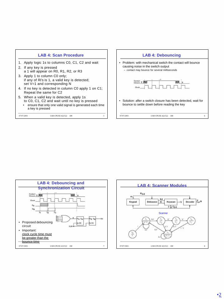
•1 CPE/EE 422/522 Advanced Logic Design L12 Electrical and Computer Engineering University of Alabama in Huntsville 07/07/2003 UAH-CPE/EE 422/522 AM 2 Outline What we know How to model Combinational Networks in VHDL Structural, Dataflow, Behavioral How to model Flip-flops in VHDL – Processes Delays (delta, transport, inertial) How to model FSM in VHDL Wait statements Variables, Signals, Arrays What we do not know VHDL Operators Procedures, Functions Packages, Libraries Additional Topics (if time) 07/07/2003 UAH-CPE/EE 422/522 AM 3 LAB 4: Keypad Scanner Lab4 preparation material Telephone keypad scanner – Section 3.5 in the textbook – Implemented using PLD (not relevant for you) 07/07/2003 UAH-CPE/EE 422/522 AM 4 LAB 4: Block Diagram Keypad is wired in matrix form switches are at the intersections of rows and columns Assumption: only one key is pressed at time N=N3N2N1N0 0 – 0000 ... 9 – 1001 * - 1010 # - 1011 V=1: when valid key is detected it is active for one clock cycle time
Transcript

•1

CPE/EE 422/522Advanced Logic Design

L12Electrical and Computer EngineeringUniversity of Alabama in Huntsville

07/07/2003 UAH-CPE/EE 422/522 AM 2

Outline

• What we know– How to model Combinational Networks in VHDL

• Structural, Dataflow, Behavioral

– How to model Flip-flops in VHDL– Processes– Delays (delta, transport, inertial)– How to model FSM in VHDL– Wait statements– Variables, Signals, Arrays

• What we do not know– VHDL Operators– Procedures, Functions– Packages, Libraries– Additional Topics (if time)

07/07/2003 UAH-CPE/EE 422/522 AM 3

LAB 4: Keypad Scanner

• Lab4 preparation material• Telephone keypad scanner

– Section 3.5 in the textbook– Implemented using PLD (not relevant for you)

07/07/2003 UAH-CPE/EE 422/522 AM 4

LAB 4: Block Diagram

• Keypad is wired in matrix form – switches are at the intersections of rows and columns

• Assumption: only one key is pressed at time • N=N3N2N1N0• 0 – 0000• ...• 9 – 1001• * - 1010• # - 1011

• V=1: when valid key is detected it is active for one clock cycle time

•2

07/07/2003 UAH-CPE/EE 422/522 AM 5

LAB 4: Scan Procedure

1. Apply logic 1s to columns C0, C1, C2 and wait2. If any key is pressed

a 1 will appear on R0, R1, R2, or R33. Apply 1 to column C0 only;

if any of Ri’s is 1, a valid key is detected;set V=1 and corresponding N

4. If no key is detected in column C0 apply 1 on C1;Repeat the same for C2

5. When a valid key is detected, apply 1s to C0, C1, C2 and wait until no key is pressed

• ensure that only one valid signal is generated each time a key is pressed

07/07/2003 UAH-CPE/EE 422/522 AM 6

LAB 4: Debouncing

• Problem: with mechanical switch the contact will bounce causing noise in the switch output – contact may bounce for several milliseconds

• Solution: after a switch closure has been detected, wait for bounce to settle down before reading the key

07/07/2003 UAH-CPE/EE 422/522 AM 7

LAB 4: Debouncing and Synchronization Circuit

• Proposed debouncing circuit

• Important:clock cycle time must be greater than the bounce time

07/07/2003 UAH-CPE/EE 422/522 AM 8

LAB 4: Scanner Modules

Scanner

•3

07/07/2003 UAH-CPE/EE 422/522 AM 9

LAB 4: Scanner

• Problem: what is Kd in S5 if we have a key pressed in column C2?

• Solution

07/07/2003 UAH-CPE/EE 422/522 AM 10

LAB 4: Decoder

07/07/2003 UAH-CPE/EE 422/522 AM 11

Review: VHDL Functions

• Functions execute a sequential algorithm and return a single value to calling program

• A = “10010101”

• General form

07/07/2003 UAH-CPE/EE 422/522 AM 12

Review: For Loops

•4

07/07/2003 UAH-CPE/EE 422/522 AM 13

Review: VHDL Procedures

• Facilitate decomposition of VHDL code into modules• Procedures can return any number of values

using output parameters

procedure_name (actual-parameter-list);

• General formprocedure procedure_name (formal-parameter-list) is

[declarations]beginSequential-statements

end procedure_name;

07/07/2003 UAH-CPE/EE 422/522 AM 14

Review: Parameters for Subprogram Calls

07/07/2003 UAH-CPE/EE 422/522 AM 15

Packages and Libraries

• Provide a convenient way of referencing frequently used functions and components

• Package declaration

• Package body [optional]

07/07/2003 UAH-CPE/EE 422/522 AM 16

Library BITLIB – bit_pack package

•5

07/07/2003 UAH-CPE/EE 422/522 AM 17

Library BITLIB – bit_pack package

07/07/2003 UAH-CPE/EE 422/522 AM 18

Library BITLIB – bit_pack package

07/07/2003 UAH-CPE/EE 422/522 AM 19

Additional Topics in VHDL

• Attributes• Transport and Inertial Delays

• Operator Overloading• Multivalued Logic and Signal Resolution

• IEEE 1164 Standard Logic

• Generics• Generate Statements

• Synthesis of VHDL Code• Synthesis Examples

• Files and Text IO

07/07/2003 UAH-CPE/EE 422/522 AM 20

Signal Attributes

Attributes associated with signals that return a value

A’event – true if a change in S has just occurred

A’active – true if A has just been reevaluated, even if A does not change

•6

07/07/2003 UAH-CPE/EE 422/522 AM 21

Signal Attributes (cont’d)

• Event– occurs on a signal every time it is changed

• Transaction– occurs on a signal every time it is evaluated

• Example:

A <= B - - B changes at time T

A’event

T + 1d

T

B’event

07/07/2003 UAH-CPE/EE 422/522 AM 22

Signal Attributes (cont’d)entity test isend;architecture bmtest of test is

signal A : bit;signal B : bit;signal C : bit;

beginA <= not A after 20 ns;B <= '1';C <= A and B;

process(A, B, C) variable Aev : bit;variable Aac : bit;variable Bev : bit;variable Bac : bit;variable Cev : bit;variable Cac : bit;

beginif (A'event) then Aev := '1';else Aev := '0';end if;if (A'active) then Aac := '1';else Aac := '0';end if;if (B'event) then Bev := '1';else Bev := '0';end if;if (B'active) then Bac := '1';else Bac := '0';end if;if (C'event) then Cev := '1';else Cev := '0';end if;if (C'active) then Cac := '1';else Cac := '0';end if;

end process;

end bmtest;

07/07/2003 UAH-CPE/EE 422/522 AM 23

Signal Attributes (cont’d)ns /test/a /test/line__15/bev

delta /test/b /test/line__15/bac /test/c /test/line__15/cev

/test/line__15/aev /test/line__15/cac /test/line__15/aac

0 +0 0 0 0 0 0 0 0 0 0 0 +1 0 1 0 0 0 1 1 0 1 20 +0 1 1 0 1 1 0 0 0 0 20 +1 1 1 1 0 0 0 0 1 1 40 +0 0 1 1 1 1 0 0 0 0 40 +1 0 1 0 0 0 0 0 1 1

07/07/2003 UAH-CPE/EE 422/522 AM 24

Signal Attributes (cont’d)

Attributes that create a signal

•7

07/07/2003 UAH-CPE/EE 422/522 AM 25

Examples of Signal Attributes

07/07/2003 UAH-CPE/EE 422/522 AM 26

Using Attributes for Error Checking

check: processbegin

wait until rising_edge(Clk);assert (D’stable(setup_time))

report(“Setup time violation”)severity error;

wait for hold_time;assert (D’stable(hold_time))

report(“Hold time violation”)severity error;

end process check;

07/07/2003 UAH-CPE/EE 422/522 AM 27

Assert Statement

• If boolean expression is falsedisplay the string expression on the monitor

• Severity levels: Note, Warning, Error, Failure

assert boolean-expressionreport string-expressionseverity severity-level

07/07/2003 UAH-CPE/EE 422/522 AM 28

Array Attributes

A can be either an array name or an array type.

Array attributes work with signals, variables, and constants.

•8

07/07/2003 UAH-CPE/EE 422/522 AM 29

Recap: Adding Vectors

Note: Add1 and Add2 vectors must be dimensioned as N-1 downto 0.

Use attributes to write more general procedure that places no restrictions on the range of vectors other than the lengths m ust be same.

07/07/2003 UAH-CPE/EE 422/522 AM 30

Procedure for Adding Bit Vectors

07/07/2003 UAH-CPE/EE 422/522 AM 31

Transport and Inertial Delay

07/07/2003 UAH-CPE/EE 422/522 AM 32

Transport and Inertial Delay (cont’d)Z3 <= reject 4 ns X after 10 ns;

Reject is equivalent to a combination of inertial and transport delay:Zm <= X after 4 ns;

Z3 <= transport Zm after 6 ns;

A <= transport B after 1 ns;

A <= transport C after 2 ns;

Statements executed at time T – B at T+1, C at T+2

Statements executed at time T – C at T + 2:

A <= B after 1 ns;

A <= C after 2 ns;

Statements executed at time T – C at T + 1:

A <= transport B after 2 ns;

A <= transport C after 1 ns;

•9

07/07/2003 UAH-CPE/EE 422/522 AM 33

Operator Overloading

• Operators +, - operate on integers • Write procedures for bit vector addition/subtraction

– addvec, subvec• Operator overloading allows using + operator

to implicitly call an appropriate addition function• How does it work?

– When compiler encounters a function declaration in which the function name is an operator enclosed in double quotes, the compiler treats the function as an operator overloading (“+”)

– when a “+” operator is encountered, the compiler automatically checks the types of operands and calls appropriate functions

07/07/2003 UAH-CPE/EE 422/522 AM 34

VHDL Package with Overloaded Operators

07/07/2003 UAH-CPE/EE 422/522 AM 35

Overloaded Operators

• A, B, C – bit vectors• A <= B + C + 3 ?

• A <= 3 + B + C ?

• Overloading can also be applied to procedures and functions– procedures have the same name –

type of the actual parameters in the procedure call determines which version of the procedure is called

07/07/2003 UAH-CPE/EE 422/522 AM 36

Multivalued Logic

• Bit (0, 1)• Tristate buffers and buses =>

high impedance state ‘Z’

• Unknown state ‘X’ – e. g., a gate is driven by ‘Z’, output is unknown– a signal is simultaneously driven by ‘0’ and ‘1’

•10

07/07/2003 UAH-CPE/EE 422/522 AM 37
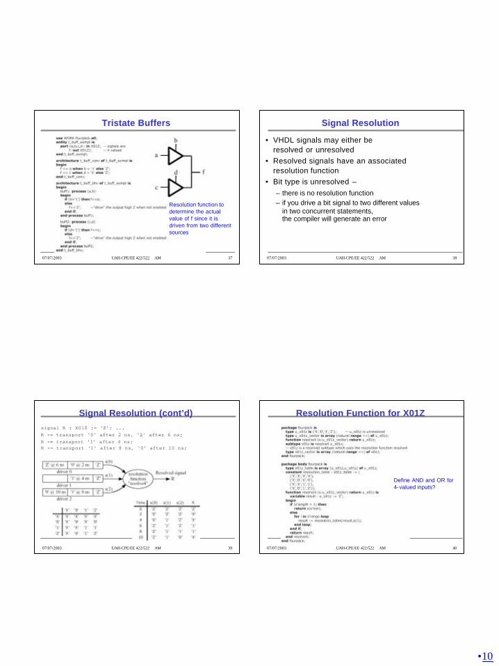
Tristate Buffers

Resolution function to determine the actual value of f since it is driven from two different sources

07/07/2003 UAH-CPE/EE 422/522 AM 38

Signal Resolution

• VHDL signals may either be resolved or unresolved

• Resolved signals have an associated resolution function

• Bit type is unresolved –– there is no resolution function– if you drive a bit signal to two different values

in two concurrent statements, the compiler will generate an error

07/07/2003 UAH-CPE/EE 422/522 AM 39

Signal Resolution (cont’d)signal R : X01Z := ‘Z’; ...R <= transport ‘0’ after 2 ns, ‘Z’ after 6 ns;R <= transport ‘1’ after 4 ns;R <= transport ‘1’ after 8 ns, ‘0’ after 10 ns;

07/07/2003 UAH-CPE/EE 422/522 AM 40

Resolution Function for X01Z

Define AND and OR for 4- valued inputs?

•11

07/07/2003 UAH-CPE/EE 422/522 AM 41

AND and OR Functions Using X01Z

‘X’‘X’‘0’‘X’‘Z’

‘X’‘1’‘0’‘X’‘1’

‘0’‘0’‘0’‘0’‘0’

‘X’‘X’‘0’‘X’‘X’

‘Z’‘1’‘0’‘X’AND

‘X’‘1’‘X’‘X’‘Z’

‘1’‘1’‘1’‘1’‘1’

‘X’‘1’‘0’‘X’‘0’

‘X’‘1’‘X’‘X’‘X’

‘Z’‘1’‘0’‘X’OR

07/07/2003 UAH-CPE/EE 422/522 AM 42

IEEE 1164 Standard Logic

• 9-valued logic system– ‘U’ – Uninitialized– ‘X’ – Forcing Unknown– ‘0’ – Forcing 0– ‘1’ – Forcing 1– ‘Z’ – High impedance– ‘W’ – Weak unknown– ‘L’ – Weak 0– ‘H’ – Weak 1– ‘-’ – Don’t care

If forcing and weak signal are tied together, the forcing signal dominates.

Useful in modeling the internal operation of certain types of ICs.

In this course we use a subset of the IEEE values: X10Z

07/07/2003 UAH-CPE/EE 422/522 AM 43

Resolution Function for IEEE 9-valued

07/07/2003 UAH-CPE/EE 422/522 AM 44

AND Table for IEEE 9-valued

•12

07/07/2003 UAH-CPE/EE 422/522 AM 45

AND Function for std_logic_vectors


Recommended