Please read through this instruction manual before use.
This instruction manual describes important precautions and instruc-tions for the product. Always keep it on hand for quick reference.
Instruction manual
IX series
Safety instructionsO
utlineInstallation
Operation
Maintenance
Specification
2
Order confirmationOpen the package and check that the product conforms to your order. Also, check each of the following points. For any problem or inconsistency, contact your distributor at once.
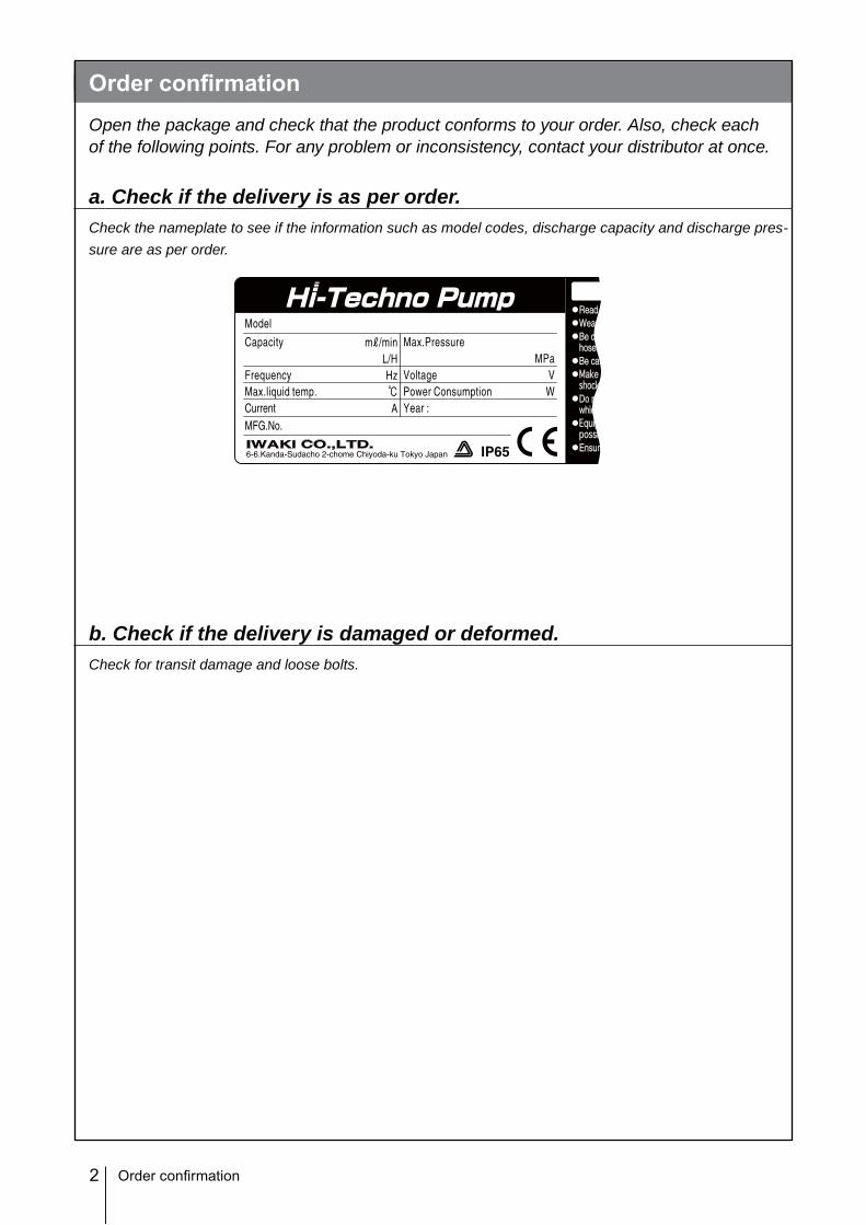
a. Check if the delivery is as per order.Check the nameplate to see if the information such as model codes, discharge capacity and discharge pres-sure are as per order.
b. Check if the delivery is damaged or deformed.Check for transit damage and loose bolts.
Precautions for use .................................................................................................................................... 10
Features ................................................................................................................................................... 13
Operational function ................................................................................................................................. 13
AUX function ....................................................................................................................................... 16
Priming function .................................................................................................................................. 16
STOP function ..................................................................................................................................... 16
Pre-STOP function .............................................................................................................................. 17
Output function .................................................................................................................................... 19
Other functions .................................................................................................................................... 19
Part names ...................................................................................................................................................20
Drain port (Vent hole) .................................................................................................................................26
End terminals ........................................................................................................................................... 27
Power supply/Earthing .............................................................................................................................28
Signal wire connection .............................................................................................................................29
STOP signal ........................................................................................................................................30
Input signal ..........................................................................................................................................30
AUX signal........................................................................................................................................... 31
Output signal ....................................................................................................................................... 31
Before operation .........................................................................................................................................32
Points to be checked ................................................................................................................................32
Retightening of pump head fixing bolts .................................................................................................... 32
Before a long period of stoppage (One month or more) ..........................................................................33
Perform a calibration ..................................................................................................................................34
Calibration process ..................................................................................................................................35
Menu screen ............................................................................................................................................39
Data logging ........................................................................................................................................46
Programming of other functions .......................................................................................................... 47
Priming function .......................................................................................................................................50
Wear parts replacement .............................................................................................................................54
Wear part list ............................................................................................................................................54
Before replacement ..................................................................................................................................55
Valve set replacement ..............................................................................................................................55
Discharge line .....................................................................................................................................55
Suction line ..........................................................................................................................................56
Control unit ..........................................................................................................................................64
Power cable ........................................................................................................................................65
Body colour .........................................................................................................................................65
Read through this section before use. This section describes important information for you to prevent personal injury or property damage.
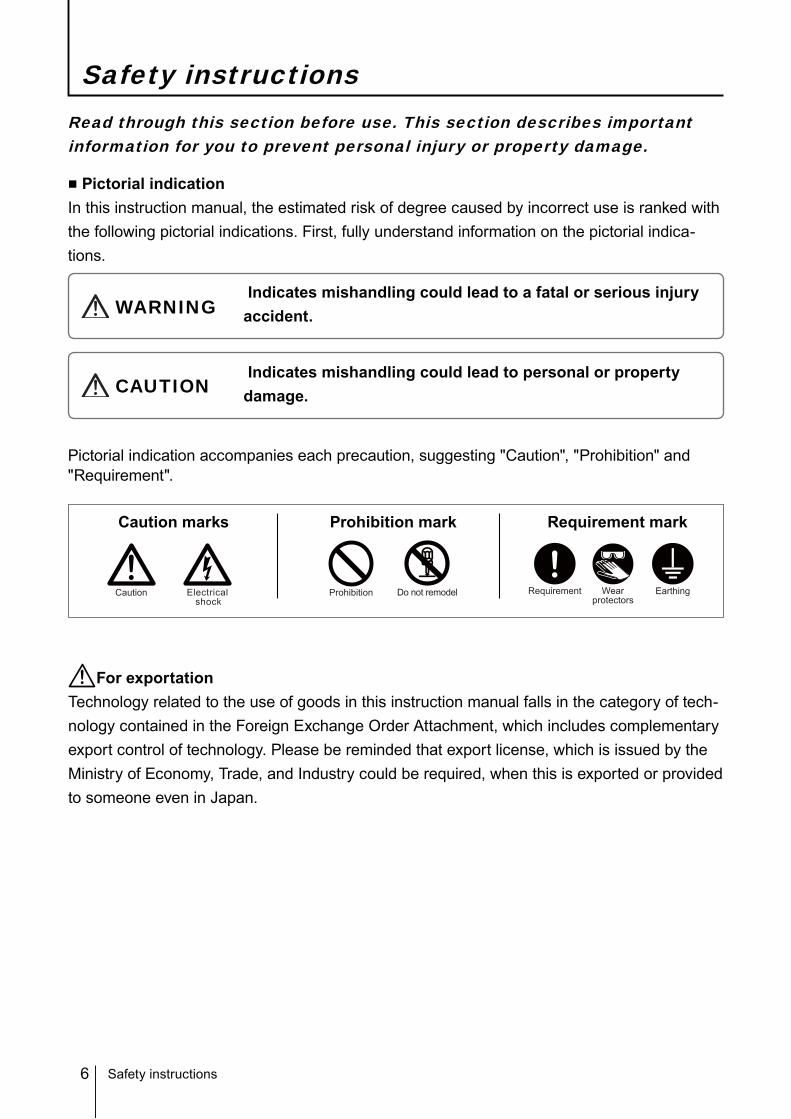
■ Pictorial indicationIn this instruction manual, the estimated risk of degree caused by incorrect use is ranked with the following pictorial indications. First, fully understand information on the pictorial indica-tions.
Indicates mishandling could lead to a fatal or serious injury accident.WARNING
Pictorial indication accompanies each precaution, suggesting "Caution", "Prohibition" and "Requirement".
Indicates mishandling could lead to personal or property damage.CAUTION
Caution marks Prohibition mark Requirement mark
Safety instructions
Safety instructions
ProhibitionElectricalshock
Caution Do not remodel Requirement Wearprotectors
Earthing
For exportationTechnology related to the use of goods in this instruction manual falls in the category of tech-nology contained in the Foreign Exchange Order Attachment, which includes complementary export control of technology. Please be reminded that export license, which is issued by the Ministry of Economy, Trade, and Industry could be required, when this is exported or provided to someone even in Japan.
7
Safety instructions
WARNING
WARNING
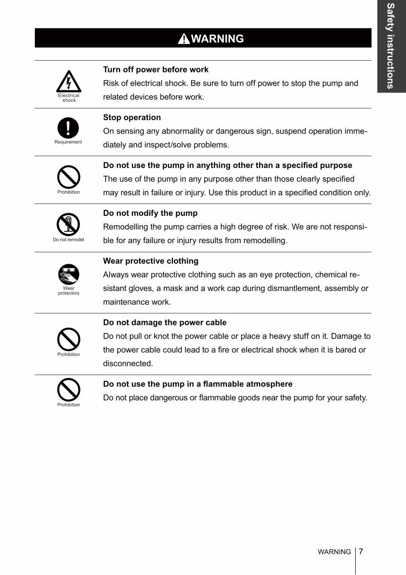
Turn off power before workRisk of electrical shock. Be sure to turn off power to stop the pump and
related devices before work.
Stop operationOn sensing any abnormality or dangerous sign, suspend operation imme-
diately and inspect/solve problems.
Do not use the pump in anything other than a specified purposeThe use of the pump in any purpose other than those clearly specified
may result in failure or injury. Use this product in a specified condition only.
Do not modify the pumpRemodelling the pump carries a high degree of risk. We are not responsi-
ble for any failure or injury results from remodelling.
Wear protective clothingAlways wear protective clothing such as an eye protection, chemical re-
sistant gloves, a mask and a work cap during dismantlement, assembly or
maintenance work.
Do not damage the power cableDo not pull or knot the power cable or place a heavy stuff on it. Damage to
the power cable could lead to a fire or electrical shock when it is bared or
disconnected.
Do not use the pump in a flammable atmosphereDo not place dangerous or flammable goods near the pump for your safety.
Prohibition
Requirement
Do not remodel
Wearprotectors
Electricalshock
Prohibition
Prohibition
8
CAUTION
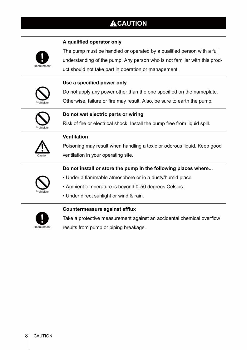
A qualified operator only
The pump must be handled or operated by a qualified person with a full
understanding of the pump. Any person who is not familiar with this prod-
uct should not take part in operation or management.
Use a specified power only
Do not apply any power other than the one specified on the nameplate.
Otherwise, failure or fire may result. Also, be sure to earth the pump.
Do not wet electric parts or wiring
Risk of fire or electrical shock. Install the pump free from liquid spill.
Ventilation
Poisoning may result when handling a toxic or odorous liquid. Keep good
ventilation in your operating site.
Do not install or store the pump in the following places where...
• Under a flammable atmosphere or in a dusty/humid place.
• Ambient temperature is beyond 0-50 degrees Celsius.
• Under direct sunlight or wind & rain.
Countermeasure against efflux
Take a protective measurement against an accidental chemical overflow
results from pump or piping breakage.
Prohibition
Requirement
Prohibition
Prohibition
Caution
Requirement
CAUTION
9
Safety instructions
Do not use the pump in a water place
The pump is not totally waterproof. The use of the pump in water or high
humidity could lead to electrical shock or short circuit.
Earthing
Risk of electrical shock. Always earth the pump.
Install an earth leakage breaker
An electrical failure of the pump may adversely affect related devices. Pur-
chase and install an earth leakage breaker separately.
Wear part replacement
Follow instructions in this manual for wear part replacement. Do not dis-
mantle the pump beyond the extent of the instructions.
Do not use a damaged pump
Using a damaged pump could lead to an electric leak or shock.
Disposal of a used pump
Dispose of any used or damaged pump in accordance with relevant regu-
lations. Consult a licensed industrial waste products disposing company.
Tighten the pump head
Liquid may leak if eight M8 pump head fixing bolts have been loosened.
Remove a bolt cover and tighten the bolts diagonally and uniformly by 10
N•m before initial operation or at periodic intervals.
Earthing
Prohibition
Requirement
Requirement
Caution
Prohibition
Electricalshock
CAUTION
10
Precautions for use
Precautions for use
• Electrical work should be performed by a qualified operator. Otherwise,
personal injury or property damage accident may result.
• Do not install the pump in the following places where...
–Under a flammable atmosphere or in a dusty/humid place.
–Under direct sunlight or wind & rain.
– Ambient temperature is beyond 0-50 degrees Celsius.
• Select a level location where is free from vibration and liquid can't stay.
Anchor the pump with four M8 bolts so as not to vibrate. If the pump is
installed at a tilt, the flow may reduce.
• When two or more pumps are installed, the pumps may start to vibrate
significantly, resulting in poor performance or failure of internal electrical
devices. Select a concrete foundation and fasten anchor bolts tightly to
prevent the pumps from vibrating during operation.
• There should be sufficient space around the pump to enable efficient and
easy maintenance.
• Install the pump as close to a supply tank as possible.
• Install the pump in a cool and dark place when handling liquids that readily
generate gas bubbles such as sodium hypochlorite or hydrazine solution.
Flooded suction application is strongly recommended when mounting the
pump below the level of liquid in the supply tank.
• The suction line bore should be wider than the inlet bore of the pump.
Caution
Caution
Caution
Caution
Caution
Caution
11
Safety instructions
• Keep the pump free from any effect of piping expansion and contraction
due to thermal stress.
• Overload protection will stop operation when the discharge pressure has
risen to 1.5 to 2 times higher than the maximum. Install a relief valve to de-
pressurize a discharge line if the pressure resistance of discharge line will
not bear the possible highest pressure.
• Be careful not to drop the pump onto the floor. A strong impact may reduce
pump performance. Do not use a pump which has once damaged. Other-
wise an electrical leak or shock may result.
• The pump is water-/dust-proof of IP65, but is not totally waterproof. Do not
have the pump wet with the liquid handled or rainwater.
• Never wet the pump head, control unit and drive unit. Otherwise, Failure or
an accident may result. Immediately wipe off liquid if the pump has got wet.
• Do not close the discharge line during operation. Otherwise, liquid may
leak or piping may break. Install a relief valve to be sure to prevent a leak
or a piping break.
• Release the pressure from the discharge line before dismantling the pump
or removing piping. Otherwise, chemical liquid gushes out.
• Be careful not to come in contact with residual liquid.
• Do not clean the pump or nameplate with a solvent such as benzene and
thinner. This may discolour the pump or erase printing. Use a dry cloth or a
wet cloth with water or neutral detergent.
Precautions for use
Caution
Caution
Caution
Requirement
Benzine
Thinner
Requirement
Caution
Caution
12
Outline
Introduction
The information such as characteristics, features and part names are de-scribed in this section.
Introduction
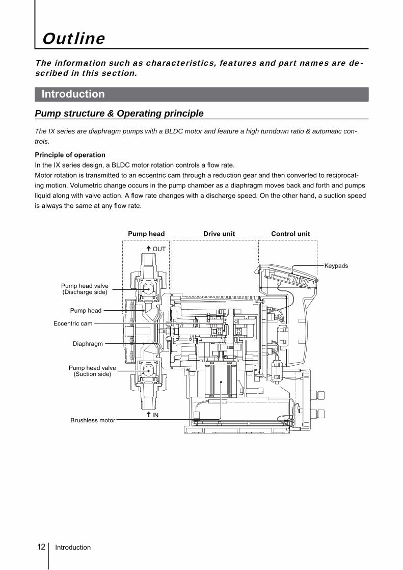
Pump structure & Operating principle
The IX series are diaphragm pumps with a BLDC motor and feature a high turndown ratio & automatic con-trols.
Principle of operationIn the IX series design, a BLDC motor rotation controls a flow rate.Motor rotation is transmitted to an eccentric cam through a reduction gear and then converted to reciprocat-ing motion. Volumetric change occurs in the pump chamber as a diaphragm moves back and forth and pumps liquid along with valve action. A flow rate changes with a discharge speed. On the other hand, a suction speed is always the same at any flow rate.
Control unitPump head Drive unit
Pump head
Pump head valve(Discharge side)
Pump head valve(Suction side)
Eccentric cam
Diaphragm
Brushless motor
Keypads
IN
OUT
13
Outline
Features
● High turndown ratioUse of a BLDC control motor offers 750:1 turndown ratio.
● High repeatabilityHighly-efficient valve design and accurate discharge-/suction-speed controls assure the high repeatability of chemical dosing (±1%).
● Energy-saving designUse of helical gears and an assist spring reduces the power consumption by 70% compared to our conven-tional metering pump designs (spring back).
● Automatic controlThe IX can automatically run along with analogue-, pulse-, batch- or interval batch-operation programming.
● Multi voltage operationThe IX series can be used in all countries thanks to the universal power supply (100-240VAC).
● Safety designA diaphragm rupture detection ensures user safety and an overload detection protects the pump and pipe-work from an accidental discharge line pressure rise.
Operational function
■ Manual operation (See page 50)The start/stop of the pump by key operationThe operation LED lights in green colour during operation.
Key operation(Push key)
Pump operation
Run
Stop
Run
Stop
Introduction
14
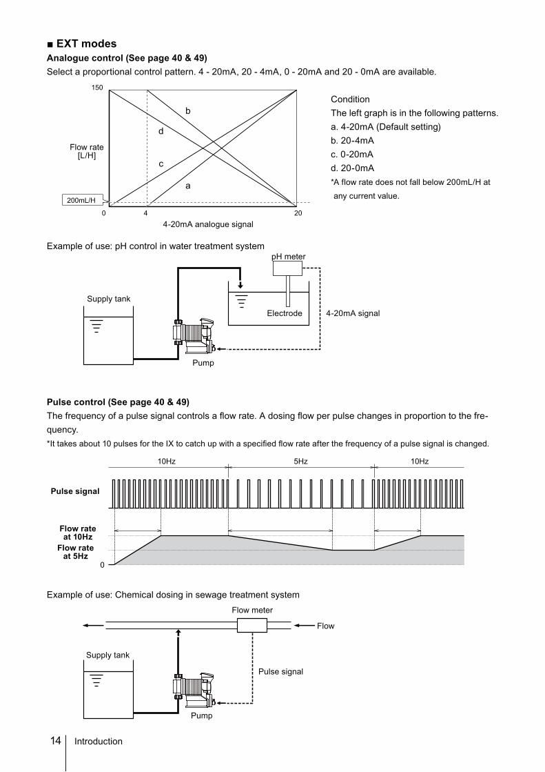
■ EXT modesAnalogue control (See page 40 & 49)Select a proportional control pattern. 4 - 20mA, 20 - 4mA, 0 - 20mA and 20 - 0mA are available.
ConditionThe left graph is in the following patterns.a. 4-20mA (Default setting)b. 20-4mAc. 0-20mAd. 20-0mA* A flow rate does not fall below 200mL/H at
any current value.
Example of use: pH control in water treatment system
Pulse control (See page 40 & 49) The frequency of a pulse signal controls a flow rate. A dosing flow per pulse changes in proportion to the fre-quency.* It takes about 10 pulses for the IX to catch up with a specified flow rate after the frequency of a pulse signal is changed.
Example of use: Chemical dosing in sewage treatment system
10Hz 5Hz 10Hz
0
Flow meter
Pulse signal
Flow
Pump
Supply tank
Supply tank
pH meter
Electrode
Pump
4-20mA signal
200mL/H
0
150
4 20
a
d
c
b
Flow rate[L/H]
4-20mA analogue signal
Pulse signal
Flow rateat 10Hz
Flow rateat 5Hz
Introduction
15
Outline
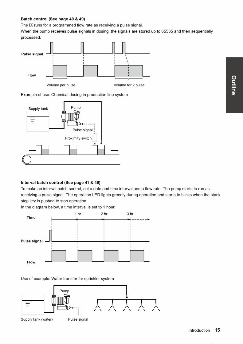
Batch control (See page 40 & 49)The IX runs for a programmed flow rate as receiving a pulse signal. When the pump receives pulse signals in dosing, the signals are stored up to 65535 and then sequentially processed.
Example of use: Chemical dosing in production line system
Interval batch control (See page 41 & 49)To make an interval batch control, set a date and time interval and a flow rate. The pump starts to run as receiving a pulse signal. The operation LED lights greenly during operation and starts to blinks when the start/stop key is pushed to stop operation.In the diagram below, a time interval is set to 1 hour.
Use of example: Water transfer for sprinkler system
Introduction
Volume per pulse Volume for 2 pulse
Pump
Supply tank (water) Pulse signal
1 hrTime
Flow
Pulse signal
2 hr 3 hr
Flow
Pulse signal
Supply tank
Pulse signal
Pump
Proximity switch
16
■ AUX function (See page 47)The pump runs at a set flow rate while receiving the external signal via the AUX terminal. Use this function for degassing or priming.*This function is available at any time except when the pump is in the MAN/EXT selection or menu selection.
■ Priming functionThe pump runs at the maximum stroke rate while both the UP and DOWN keys are pressed. Use this function for degassing.Press and hold both the keys for 10 seconds and then release the keys to leave the pump running in this state.Push the start/stop key to stop operation.*This function is available at any time except when the pump is in the MAN/EXT selection or menu selection.
■ STOP function (See page 42)The start/stop of operation can be controlled by a signal from a level sensor.See page 30 "STOP signal" for wiring diagram.
When Make-OFF is selected...The pump stops and the operation LED lights in red colour while receiving the stop signal (closed circuit).*The pump resumes operation when the stop signal is released.
Introduction
AUX signal
Pump operationRunStop RunStop
Press & hold
RunStop Pump keeps running.Stop
Release keys after 10 sec.
To stop
Pump operation
Run Stop Run
STOP signal
Pump operation
17
Outline
Introduction
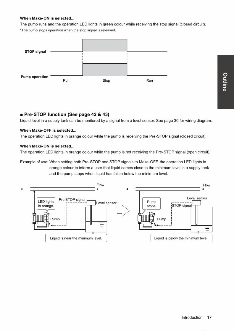
When Make-ON is selected...The pump runs and the operation LED lights in green colour while receiving the stop signal (closed circuit).*The pump stops operation when the stop signal is released.
■ Pre-STOP function (See page 42 & 43)Liquid level in a supply tank can be monitored by a signal from a level sensor. See page 30 for wiring diagram.
When Make-OFF is selected...The operation LED lights in orange colour while the pump is receiving the Pre-STOP signal (closed circuit).
When Make-ON is selected...The operation LED lights in orange colour while the pump is not receiving the Pre-STOP signal (open circuit).
Example of use: When setting both Pre-STOP and STOP signals to Make-OFF, the operation LED lights in orange colour to inform a user that liquid comes close to the minimum level in a supply tank and the pump stops when liquid has fallen below the minimum level.
Run Stop Run
STOP signal
Pump operation
LED lightsin orange. STOP signal
Pre STOP signal
PumpPump
Level sensorLevel sensor
Flow
Liquid is near the minimum level. Liquid is below the minimum level.
Flow
Pump stops.
18 Introduction
■ Protective functionsInterlock function (See page 42 &43)The start/stop of operation can be controlled by a signal from an external device.Interlock function works in the same way as the STOP function but uses a preference circuit. Use this function for emergency stop.*This function is available at any time except when the pump is in the MAN/EXT selection or menu selection.
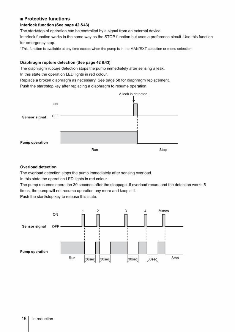
Diaphragm rupture detection (See page 42 &43)The diaphragm rupture detection stops the pump immediately after sensing a leak. In this state the operation LED lights in red colour.Replace a broken diaphragm as necessary. See page 58 for diaphragm replacement.Push the start/stop key after replacing a diaphragm to resume operation.
Overload detectionThe overload detection stops the pump immediately after sensing overload.In this state the operation LED lights in red colour.The pump resumes operation 30 seconds after the stoppage. If overload recurs and the detection works 5 times, the pump will not resume operation any more and keep still.Push the start/stop key to release this state.
OFF
ON
Run Stop
Sensor signal
Pump operation
A leak is detected.
OFF
ON1 2 3 4 5times
30sec 30sec 30sec 30sec
Sensor signal
Pump operation
Run Stop
19
Outline
Introduction
■ Output function (See page 44 & 45) Set the STOP, Pre-STOP, Interlock, Diaphragm rupture detection and Overload detection outputs to the OUT 1 and OUT2.See page 31 "Output signal" for wiring diagram.OUT1: Mechanical relay output(No voltage contact 1a×1 250VAC 3A Resistive load)OUT2: PhotoMOS relay output(No voltage contact 1a×1 24VAC/DC 0.1A Resistive load)
■ Other functionsSuction speed setting (See page 47)Suction speed is adjustable by 4 levels.Select 100%, 75%, 50% or 25%.Example of use: Viscous liquid transfer
Diaphragm position adjustment (See page 47 & 48)A pump shaft expands or contracts to help diaphragm replacement.The pump shaft comes at the top dead centre when stopping operation. Replace a diaphragm and contract the pump shaft, and then mount the pump head.See page 58 "Diaphragm replacement" for detail.
Anti chattering programming (See page 47 & 48)Program a pulse recognition time not to be adversely affected by chattering or noise.Factory default setting is 5msec.Select 1 or 2msec if a pulse frequency is high.
Flow unit setting (See page 47 & 48)Select L/H or GPH for flow rate indication.
20 Part names
Part names
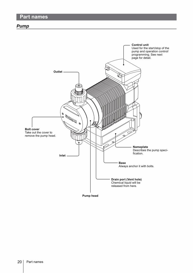
Pump
Control unitUsed for the start/stop of the pump and operation control/programming. See next page for detail.
Bolt coverTake out the cover to remove the pump head.
Drain port (Vent hole)Chemical liquid will be released from here.
NameplateDescribes the pump speci-fication.
BaseAlways anchor it with bolts.
Outlet
Pump head
Inlet
21
Outline
Part names
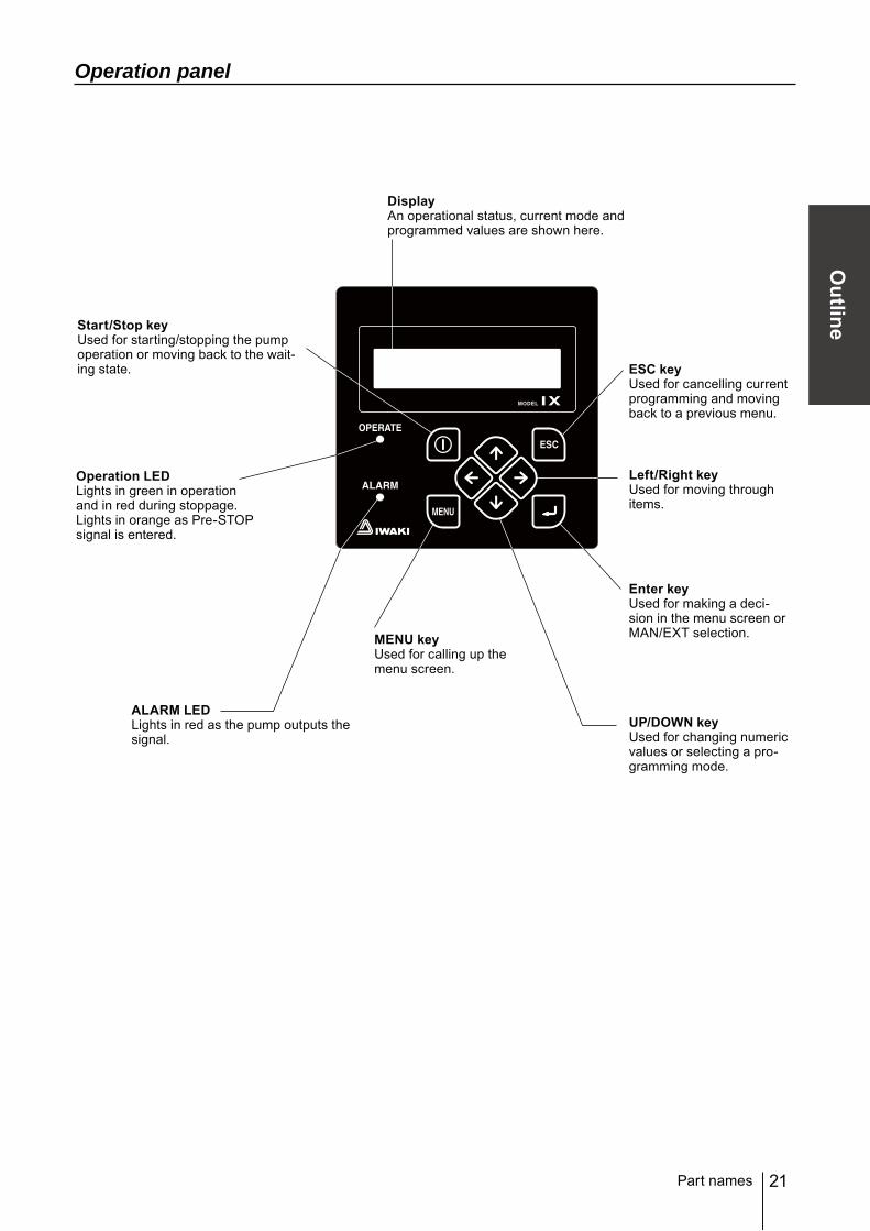
Operation panel
UP/DOWN keyUsed for changing numeric values or selecting a pro-gramming mode.
MENU keyUsed for calling up the menu screen.
Left/Right keyUsed for moving through items.
DisplayAn operational status, current mode and programmed values are shown here.
Start/Stop keyUsed for starting/stopping the pump operation or moving back to the wait-ing state. ESC key
Used for cancelling current programming and moving back to a previous menu.
ALARM LEDLights in red as the pump outputs the signal.
Operation LEDLights in green in operation and in red during stoppage.Lights in orange as Pre-STOP signal is entered.
Enter keyUsed for making a deci-sion in the menu screen or MAN/EXT selection.
22
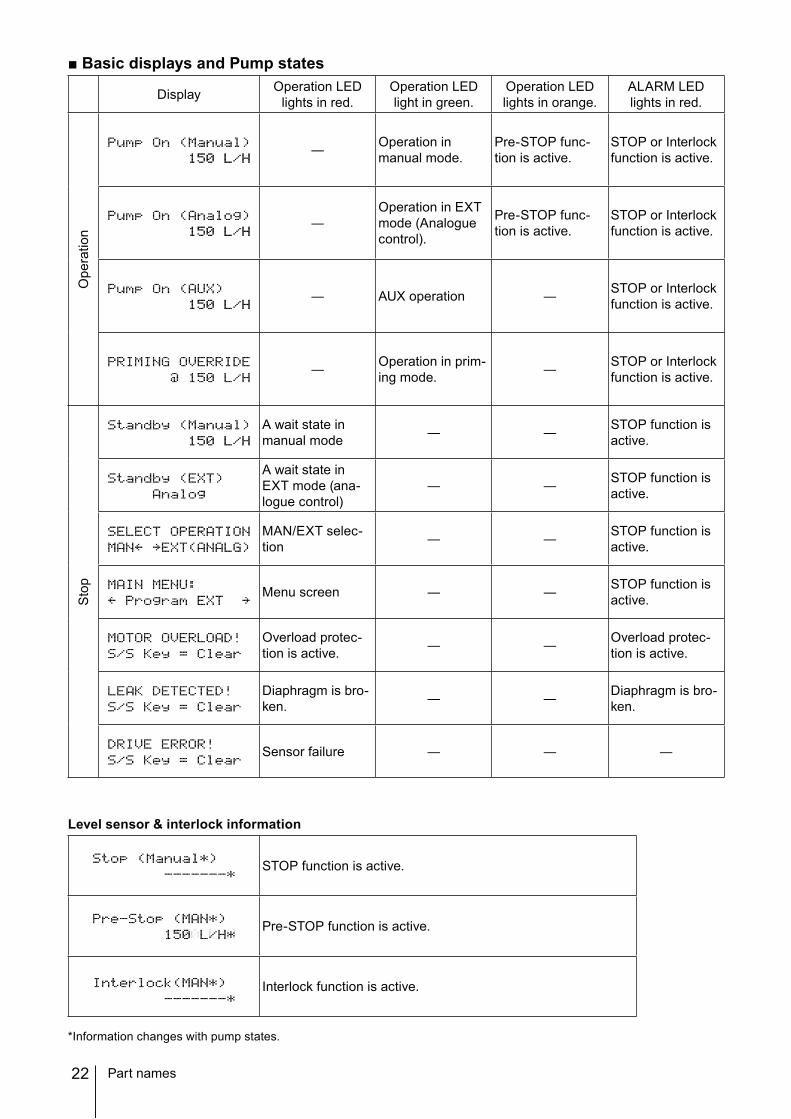
■ Basic displays and Pump states
Display Operation LEDlights in red.
Operation LEDlight in green.
Operation LEDlights in orange.
ALARM LEDlights in red.
Ope
ratio
n
― Operation in manual mode.
Pre-STOP func-tion is active.
STOP or Interlock function is active.
―Operation in EXT mode (Analogue control).
Pre-STOP func-tion is active.
STOP or Interlock function is active.
― AUX operation ― STOP or Interlock function is active.
― Operation in prim-ing mode. ― STOP or Interlock
function is active.
Sto
p
A wait state in manual mode ― ― STOP function is
active.
A wait state in EXT mode (ana-logue control)
― ― STOP function is active.
MAN/EXT selec-tion ― ― STOP function is
active.
Menu screen ― ― STOP function is active.
Overload protec-tion is active. ― ― Overload protec-
tion is active.
Diaphragm is bro-ken. ― ― Diaphragm is bro-
ken.
Sensor failure ― ― ―
Level sensor & interlock information
STOP function is active.
Pre-STOP function is active.
Interlock function is active.
*Information changes with pump states.
Part names
23
Outline
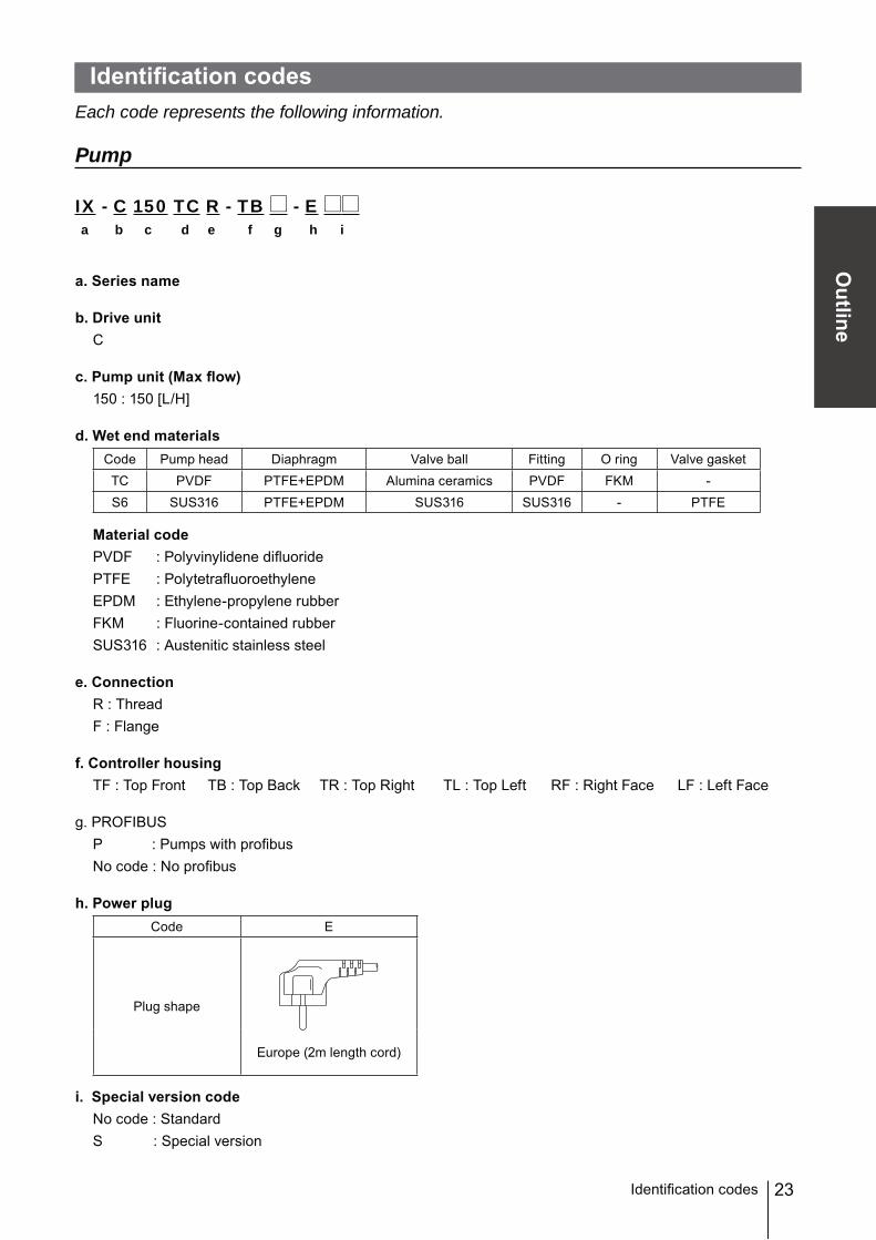
Identification codesEach code represents the following information.
Pump
IX - C 150 TC R - TB - E a b c d e f g h i
a. Series name
b. Drive unitC
c. Pump unit (Max flow)150 : 150 [L/H]
d. Wet end materialsCode Pump head Diaphragm Valve ball Fitting O ring Valve gasketTC PVDF PTFE+EPDM Alumina ceramics PVDF FKM -S6 SUS316 PTFE+EPDM SUS316 SUS316 - PTFE
f. Controller housingTF : Top Front TB : Top Back TR : Top Right TL : Top Left RF : Right Face LF : Left Face
g. PROFIBUSP : Pumps with profibusNo code : No profibus
h. Power plugCode E
Plug shape
Europe (2m length cord)
i. Special version codeNo code : StandardS : Special version
Identification codes
24
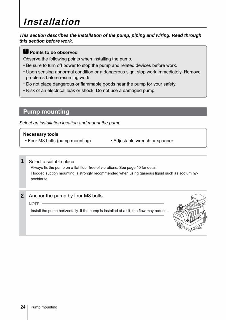
InstallationThis section describes the installation of the pump, piping and wiring. Read through this section before work.
Points to be observedObserve the following points when installing the pump.• Be sure to turn off power to stop the pump and related devices before work.• Upon sensing abnormal condition or a dangerous sign, stop work immediately. Remove
problems before resuming work.• Do not place dangerous or flammable goods near the pump for your safety.• Risk of an electrical leak or shock. Do not use a damaged pump.
Pump mounting
Select an installation location and mount the pump.
Necessary tools• Four M8 bolts (pump mounting) • Adjustable wrench or spanner
Select a suitable placeAlways fix the pump on a flat floor free of vibrations. See page 10 for detail.Flooded suction mounting is strongly recommended when using gaseous liquid such as sodium hy-pochlorite.
Anchor the pump by four M8 bolts.NOTE
Install the pump horizontally. If the pump is installed at a tilt, the flow may reduce.
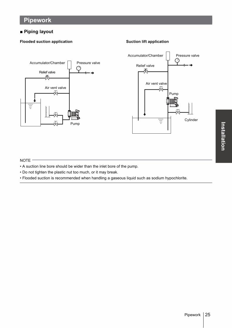
NOTE• A suction line bore should be wider than the inlet bore of the pump.• Do not tighten the plastic nut too much, or it may break.• Flooded suction is recommended when handling a gaseous liquid such as sodium hypochlorite.
Accumulator/Chamber
Pump
Relief valve
Pressure valve
Cylinder
Pipework
Accumulator/Chamber
Pump
Relief valve
Pressure valve
Air vent valveAir vent valve
26
Drain port (Vent hole)
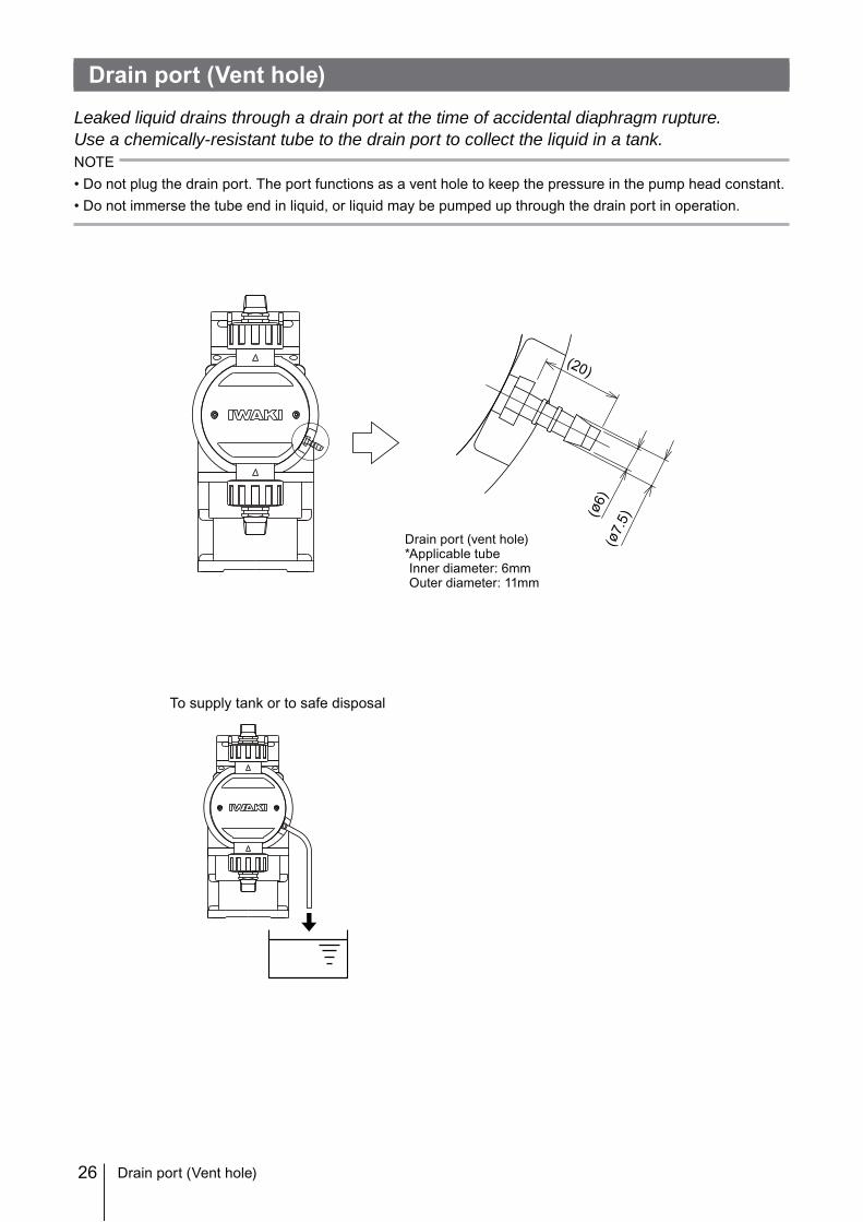
Leaked liquid drains through a drain port at the time of accidental diaphragm rupture.Use a chemically-resistant tube to the drain port to collect the liquid in a tank.NOTE• Do not plug the drain port. The port functions as a vent hole to keep the pressure in the pump head constant.• Do not immerse the tube end in liquid, or liquid may be pumped up through the drain port in operation.
(ø6)
(ø7.
5)
(20)
Drain port (vent hole)*Applicable tubeInner diameter: 6mmOuter diameter: 11mm
To supply tank or to safe disposal
Drain port (Vent hole)
27
Installation
Wiring
Wiring
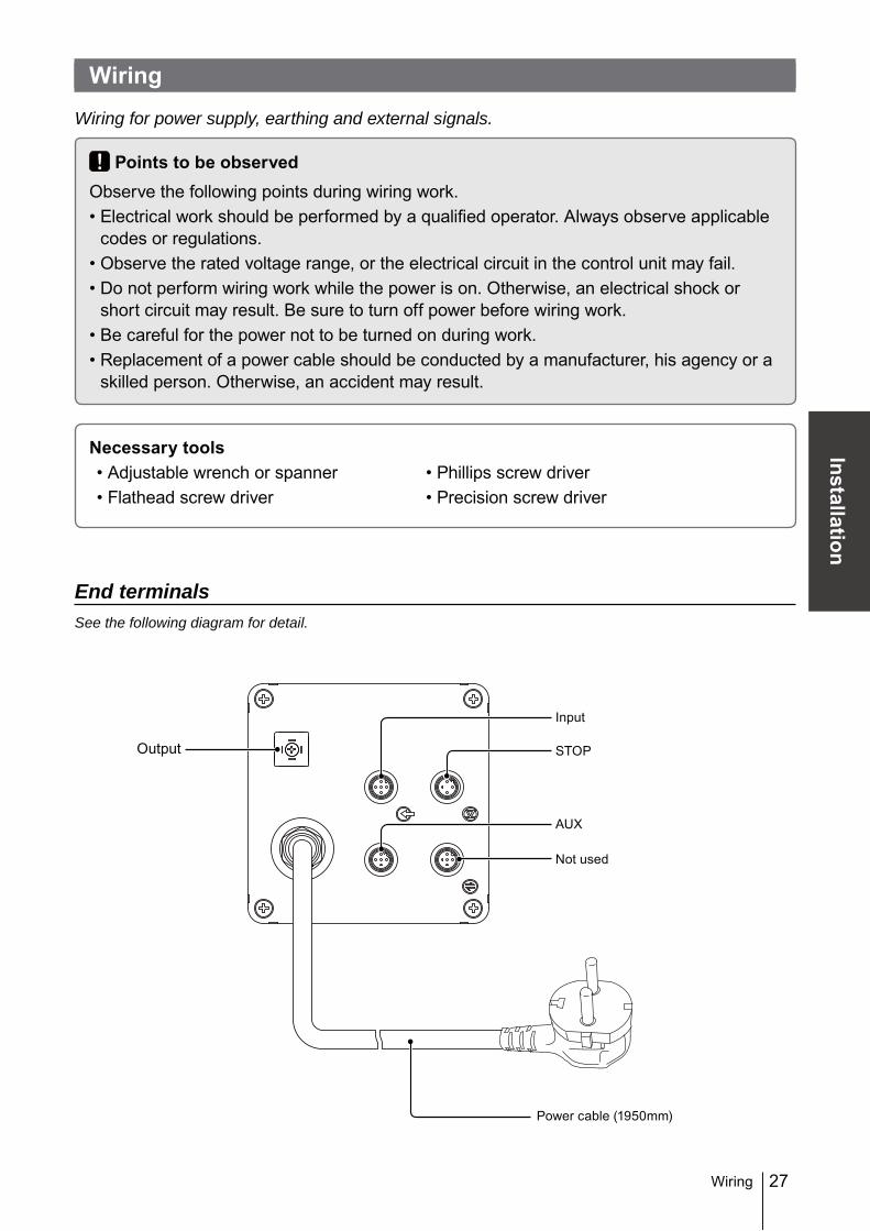
Wiring for power supply, earthing and external signals.
Points to be observedObserve the following points during wiring work.• Electrical work should be performed by a qualified operator. Always observe applicable
codes or regulations.• Observe the rated voltage range, or the electrical circuit in the control unit may fail.• Do not perform wiring work while the power is on. Otherwise, an electrical shock or
short circuit may result. Be sure to turn off power before wiring work.• Be careful for the power not to be turned on during work.• Replacement of a power cable should be conducted by a manufacturer, his agency or a
skilled person. Otherwise, an accident may result.
End terminalsSee the following diagram for detail.
AUX
STOPOutput
Input
Not used
Power cable (1950mm)
28
Power supply/Earthing
Points to be checked• Check that the main power is turned off.
Insert the plug all the way seated in a socket.
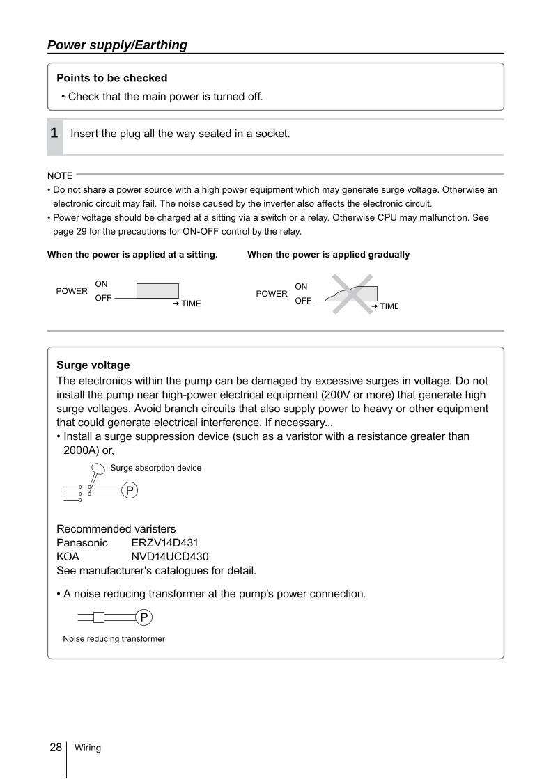
NOTE• Do not share a power source with a high power equipment which may generate surge voltage. Otherwise an
electronic circuit may fail. The noise caused by the inverter also affects the electronic circuit.• Power voltage should be charged at a sitting via a switch or a relay. Otherwise CPU may malfunction. See
page 29 for the precautions for ON-OFF control by the relay.
When the power is applied at a sitting. When the power is applied gradually
Surge voltageThe electronics within the pump can be damaged by excessive surges in voltage. Do not install the pump near high-power electrical equipment (200V or more) that generate high surge voltages. Avoid branch circuits that also supply power to heavy or other equipment that could generate electrical interference. If necessary...• Install a surge suppression device (such as a varistor with a resistance greater than
2000A) or,
Recommended varistersPanasonic ERZV14D431KOA NVD14UCD430See manufacturer's catalogues for detail.
• A noise reducing transformer at the pump’s power connection.
Surge absorption device
Noise reducing transformer
POWERON
OFF TIMEPOWER
ON
OFF TIME
1
Wiring
29
Installation
Wiring
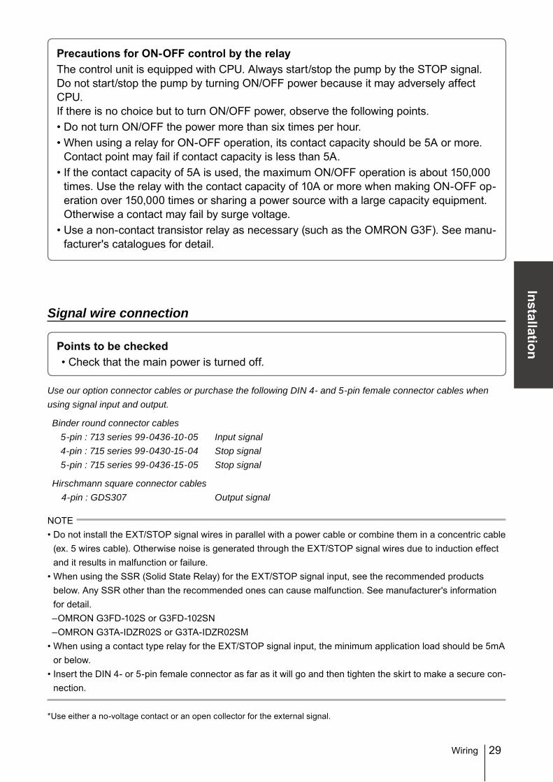
Precautions for ON-OFF control by the relayThe control unit is equipped with CPU. Always start/stop the pump by the STOP signal. Do not start/stop the pump by turning ON/OFF power because it may adversely affect CPU.If there is no choice but to turn ON/OFF power, observe the following points.• Do not turn ON/OFF the power more than six times per hour.• When using a relay for ON-OFF operation, its contact capacity should be 5A or more.
Contact point may fail if contact capacity is less than 5A.• If the contact capacity of 5A is used, the maximum ON/OFF operation is about 150,000
times. Use the relay with the contact capacity of 10A or more when making ON-OFF op-eration over 150,000 times or sharing a power source with a large capacity equipment. Otherwise a contact may fail by surge voltage.
• Use a non-contact transistor relay as necessary (such as the OMRON G3F). See manu-facturer's catalogues for detail.
Signal wire connection
Points to be checked• Check that the main power is turned off.
Use our option connector cables or purchase the following DIN 4- and 5-pin female connector cables when using signal input and output.
Binder round connector cables 5-pin : 713 series 99-0436-10-05 Input signal 4-pin : 715 series 99-0430-15-04 Stop signal 5-pin : 715 series 99-0436-15-05 Stop signal
Hirschmann square connector cables 4-pin : GDS307 Output signal
NOTE• Do not install the EXT/STOP signal wires in parallel with a power cable or combine them in a concentric cable
(ex. 5 wires cable). Otherwise noise is generated through the EXT/STOP signal wires due to induction effect and it results in malfunction or failure.
• When using the SSR (Solid State Relay) for the EXT/STOP signal input, see the recommended products below. Any SSR other than the recommended ones can cause malfunction. See manufacturer's information for detail.–OMRON G3FD-102S or G3FD-102SN–OMRON G3TA-IDZR02S or G3TA-IDZR02SM
• When using a contact type relay for the EXT/STOP signal input, the minimum application load should be 5mA or below.
• Insert the DIN 4- or 5-pin female connector as far as it will go and then tighten the skirt to make a secure con-nection.
*Use either a no-voltage contact or an open collector for the external signal.
30
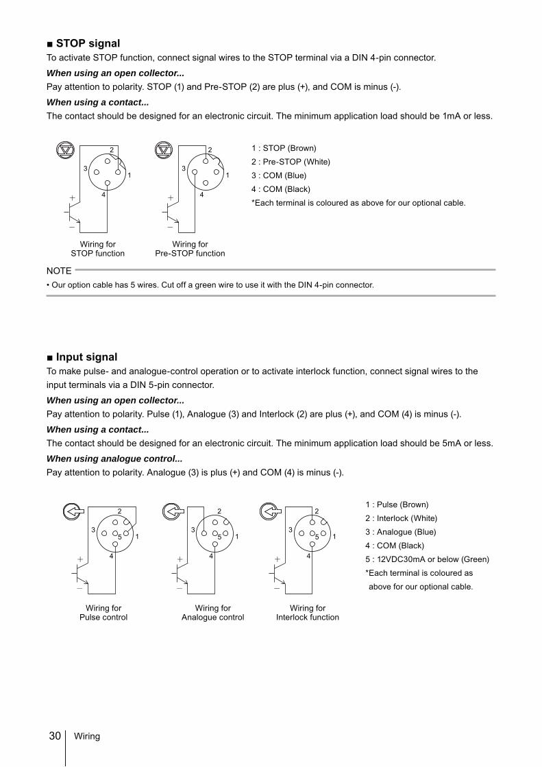
■ STOP signalTo activate STOP function, connect signal wires to the STOP terminal via a DIN 4-pin connector.
When using an open collector...Pay attention to polarity. STOP (1) and Pre-STOP (2) are plus (+), and COM is minus (-).
When using a contact...The contact should be designed for an electronic circuit. The minimum application load should be 1mA or less.
1 : STOP (Brown)
2 : Pre-STOP (White)
3 : COM (Blue)
4 : COM (Black)
* Each terminal is coloured as above for our optional cable.
NOTE• Our option cable has 5 wires. Cut off a green wire to use it with the DIN 4-pin connector.
■ Input signalTo make pulse- and analogue-control operation or to activate interlock function, connect signal wires to the input terminals via a DIN 5-pin connector.
When using an open collector...Pay attention to polarity. Pulse (1), Analogue (3) and Interlock (2) are plus (+), and COM (4) is minus (-).
When using a contact...The contact should be designed for an electronic circuit. The minimum application load should be 5mA or less.
When using analogue control...Pay attention to polarity. Analogue (3) is plus (+) and COM (4) is minus (-).
1 : Pulse (Brown)
2 : Interlock (White)
3 : Analogue (Blue)
4 : COM (Black)
5 : 12VDC30mA or below (Green)
* Each terminal is coloured as
above for our optional cable.
Wiring forSTOP function
3
2
4
13
2
4
1
Wiring forPre-STOP function
Wiring forInterlock function
3
2
4
5 13
2
4
5 13
2
4
5 1
Wiring forAnalogue control
Wiring forPulse control
Wiring
31
Installation
■ AUX signalTo activate AUX function, connect signal wires to the AUX terminal via a DIN 5-pin connector.
When using an open collector...Pay attention to polarity. AUX (3) is plus (+), and COM (4) is minus (-).
When using a contact...The contact should be designed for an electronic circuit. The minimum application load should be 5mA or less.
1 : N.C.
2 : N.C.
3 : AUX
4 : COM
5 : 12VDC30mA or below
■ Output signalTo transmit signal to an external device, connect signal wires to the OUT terminal via a DIN 4-pin connector.
OUT1<Mechanical relay>: Enable or disable STOP, Pre-STOP, Interlock, Motor overload and Leak de-tection individually.*Leak detection only is enabled at factory default setting.
OUT2<PhotoMOS relay>: Enable or disable STOP, Pre-STOP, Interlock, Motor overload and Leak de-tection individually.*Interlock only is enabled at factory default setting.
1 : OUT12 : OUT13 : OUT24 : OUT2
3
2
4
5 1
Wiring forAUX function
1
2
3
4
Wiring
32
This section describes pump operation and programming. Run the pump after pipework and wiring is completed.
Before operationFirst check piping and wiring are collect. And then make commissioning before starting op-eration.
Points to be checkedBefore operation, check if...• Liquid level in the supply tank is enough.• Piping is securely connected and is free from leakage and clogging• Discharge/suction valves are opened.• Specified power voltage is applied to the pump.• Electrical wiring is correct and is free from short circuit and electrical leakage.
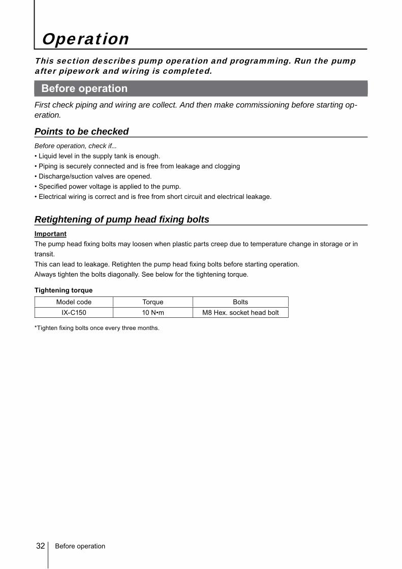
Retightening of pump head fixing boltsImportantThe pump head fixing bolts may loosen when plastic parts creep due to temperature change in storage or in transit.This can lead to leakage. Retighten the pump head fixing bolts before starting operation.Always tighten the bolts diagonally. See below for the tightening torque.
Tightening torque
Model code Torque BoltsIX-C150 10 N•m M8 Hex. socket head bolt
*Tighten fixing bolts once every three months.
Operation
Before operation
33
Operation
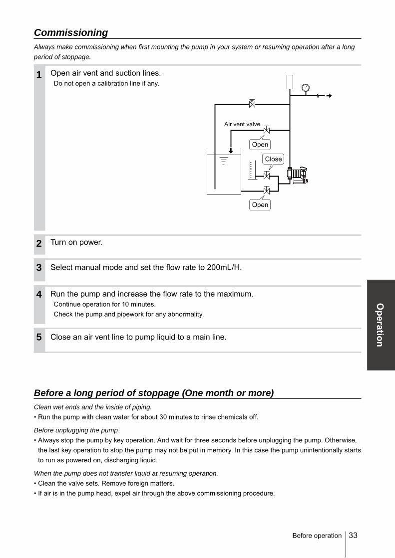
CommissioningAlways make commissioning when first mounting the pump in your system or resuming operation after a long period of stoppage.
Open air vent and suction lines.Do not open a calibration line if any.
Turn on power.
Select manual mode and set the flow rate to 200mL/H.
Run the pump and increase the flow rate to the maximum.Continue operation for 10 minutes.Check the pump and pipework for any abnormality.
Close an air vent line to pump liquid to a main line.
Before a long period of stoppage (One month or more)Clean wet ends and the inside of piping.• Run the pump with clean water for about 30 minutes to rinse chemicals off.
Before unplugging the pump• Always stop the pump by key operation. And wait for three seconds before unplugging the pump. Otherwise,
the last key operation to stop the pump may not be put in memory. In this case the pump unintentionally starts to run as powered on, discharging liquid.
When the pump does not transfer liquid at resuming operation.• Clean the valve sets. Remove foreign matters.• If air is in the pump head, expel air through the above commissioning procedure.
Open
Open
Close
Air vent valve
2
1
3
4
5
Before operation
34
Perform a calibrationPeriodically make a calibration to monitor an accurate flow through control display.The pump has been calibrated by pumping clean water at the maximum operating pressure before shipping, however, make calibration again in an actual operating condition as neces-sary. Follow the calibration step on the next page.NOTE• The pump does not measure how much volume is being pumped. A flow rate on the screen is calculation
value based on calibration and is not an actual flow rate.
Calibration is made for determine liquid volume per shot. Arrange your pump system based on the diagram below.
Suggested piping layoutUse a calibration cylinder.
Bad example Do not immerse a calibration tube in a liquid level in a calibration cylinder. Tube volume is added to the liquid volume to be measured, and calibration will be upset.
Before calibration
Accumulator/Chamber
Pump
Pump
After calibration
Relief valve
Calibration cylinder
Air vent valve
Tube in liquid
Pressure valve
Calibration cylinder
Perform a calibration
Calibration cylinder
35
Operation
Perform a calibration
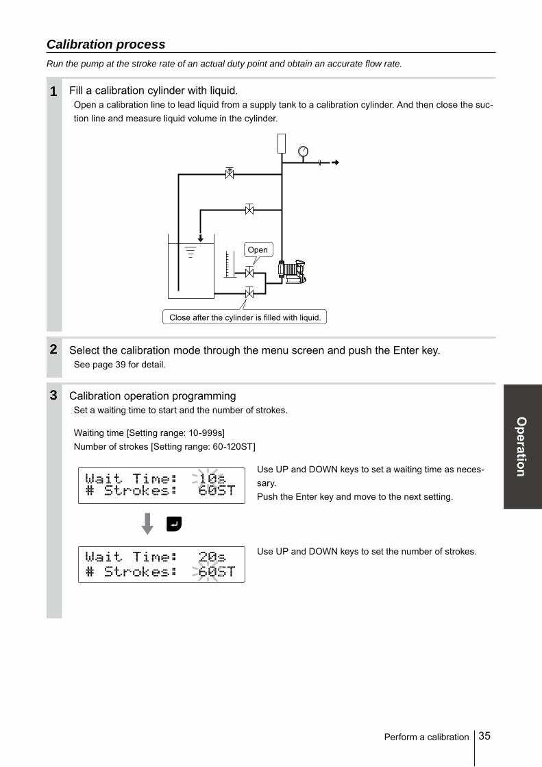
Calibration processRun the pump at the stroke rate of an actual duty point and obtain an accurate flow rate.
Fill a calibration cylinder with liquid.Open a calibration line to lead liquid from a supply tank to a calibration cylinder. And then close the suc-tion line and measure liquid volume in the cylinder.
Select the calibration mode through the menu screen and push the Enter key.See page 39 for detail.
Calibration operation programmingSet a waiting time to start and the number of strokes.
Waiting time [Setting range: 10-999s]Number of strokes [Setting range: 60-120ST]
Use UP and DOWN keys to set a waiting time as neces-sary.Push the Enter key and move to the next setting.
Use UP and DOWN keys to set the number of strokes.
Close after the cylinder is filled with liquid.
Open
2
1
3
36
Start calibration operation.Push the Enter key after setting the number of strokes. The pump starts a countdown.
The pump starts to run for the set number of strokes as it comes to zero.
Measure liquid volume in the calibration cylinder again.
Enter how much liquid volume reduces.
Use UP and DOWN keys to set the volume reduction.* The screen shows "ERROR! Volume Out Of Range!!" if the set
value is out of range. Enter collect liquid volume.
Push the Enter key once. The screen shows a flow rate per shot. Calibration is now has been completed.
Push the ESC key to return to waite mode.
Pumpstops
4
5
Pumpstarts
6
Perform a calibration
37
Operation
Operation programmingThe pump operation is programmed and controlled by a control unit in different ways at each operation mode.
Mode Parameters Setting ranges DefaultMode selection - MAN/EXT MAN
External con-trol
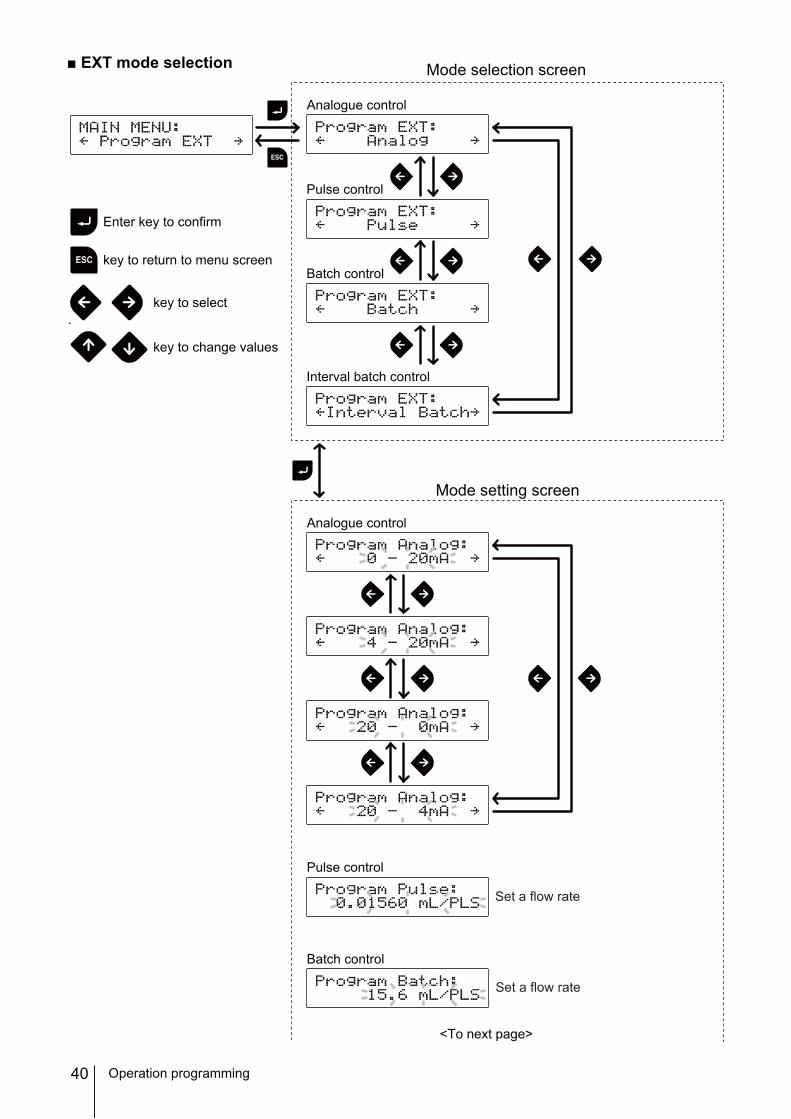
Analogue control 0-20mA/ 4-20mA/ 20-0mA/ 20-4mA 4-20mAPulse control 0.0156mL/PLS-300mL/PLS 0.01560mL/PLSBatch control 15.6mL/PLS-300L/PLS 15.6mL/PLS
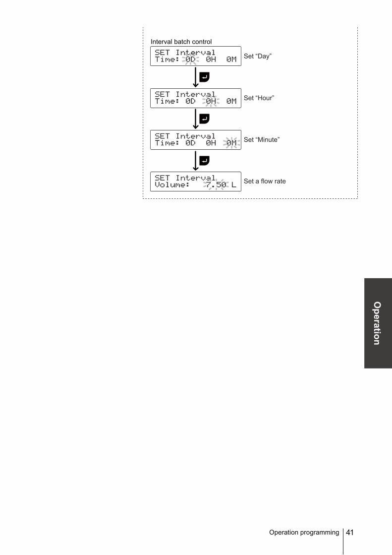
Interval Batch control 0-9day, 0-23Hr, 1-59min15.6mL-300L
Alarm 2 STOP/ Pre-STOP/ InterlockLeak Detection/ Motor Overload Interlock
Others
Suction speed 100%/ 75%/ 50%/ 25% 100%
Flow rate in AUX opera-tion 200mL/H - 150L/H 150L/H
Diaphragm position MAX OUT Pos./ MAX IN Pos. MAX OUT Pos.Anti-Chattering 1msec/ 2msec/ 5msec 5msecUnit Liter/ US. Gallon Liter
*A value increases/decreases step by step as pushing the UP/DOWN keys. Press and hold either key for quick change.
Operation programming
38
Programming flow
Operation programming
Wait state
Operation
MAN modeEXT mode
Menu screen
MAN/EXT selection
Power ON
Use keys.
*See page 39 for setting at each menue.
MAN modeEXT mode
39
Operation
Menu screenPush the MENU key while the MAN/EXT selection display appears and call up the menu screen.Push the MENU or ESC key to return to the MAN/EXT selection mode.
EXT mode selectionThe pump can run in four different operating modes of Analog, Pulse, Batch and Interval Batch for the external signal. See page 40.
CalibrationCalibrate the pump to obtain a correct flow rate on the screen. See page 42.
Signal input settingProgram STOP, Pre-STOP & Interlock functions and diaphragm rupture detection. See page 42.
Alarm 1 settingEnable or disable the Alarm 1 for STOP, Pre-STOP, Interlock and/or diaphragm rupture detection. See page 44.
Alarm 2 settingEnable or disable the Alarm 2 for STOP, Pre-STOP, Interlock and/or diaphragm rupture detection. See page 45.
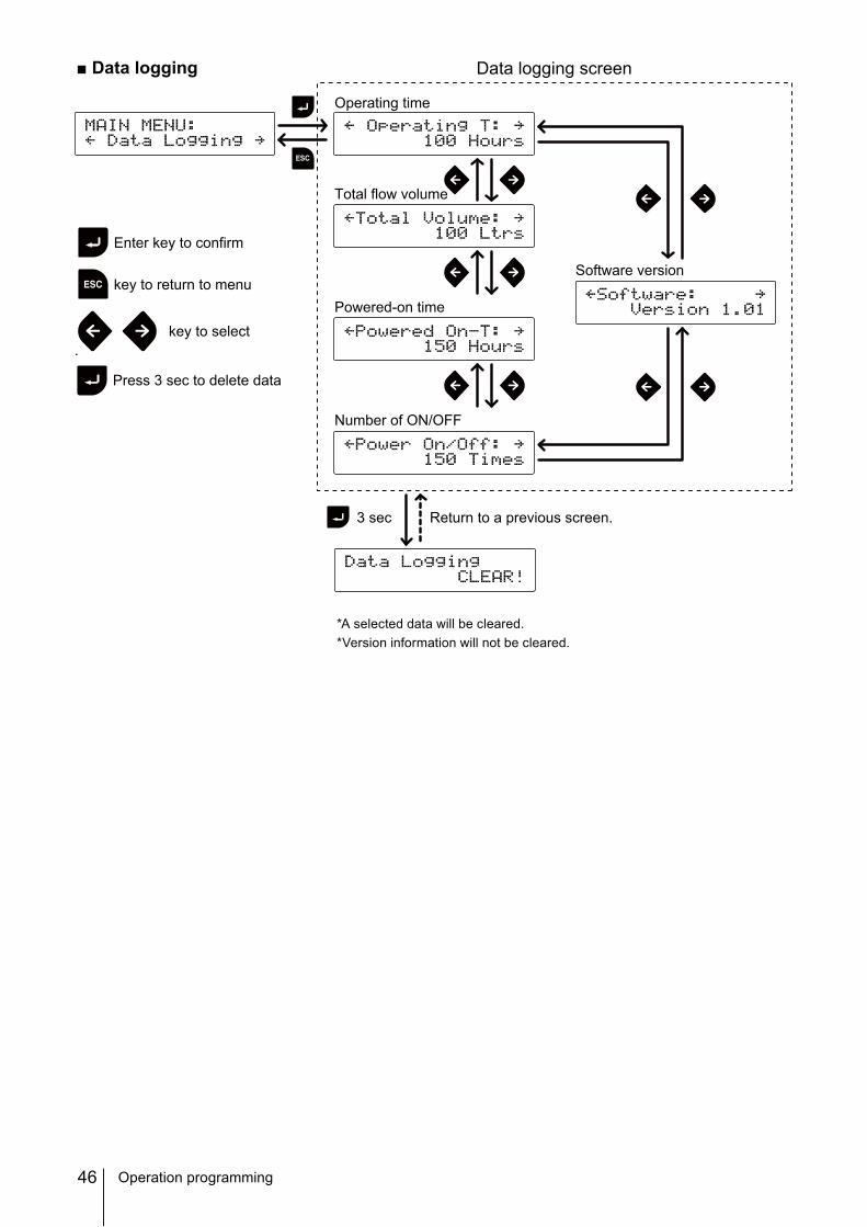
Data loggingThe pump can display operating time, total flow volume, power-on time, the number of ON/OFF and software version. See page 46.
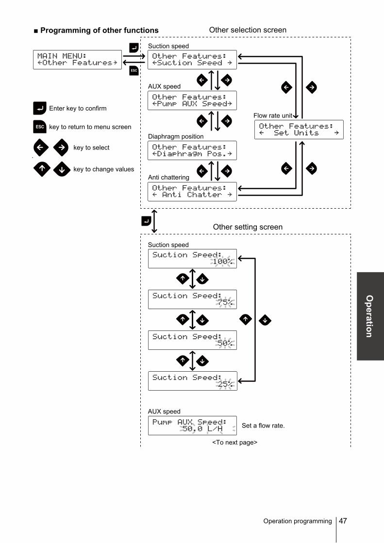
Programming of other functions.Program a suction speed, a flow rate in AUX operation, dia-phragm position, anti-chattering and flow rate unit. See page 47.
Use the left and right keys to scroll through the items and then push the Enter key to make a selection.
Operation programming
40
Pulse control
Batch control
Analogue control
Mode setting screen
Enter key to confirm
key to return to menu screen
key to select
key to change values
<To next page>
Analogue control
Pulse control
Batch control
Interval batch control
Mode selection screen
Set a flow rate
Set a flow rate
■ EXT mode selection
Operation programming
41
Operation
Operation programming
Interval batch control
Set “Day”
Set “Hour”
Set “Minute”
Set a flow rate
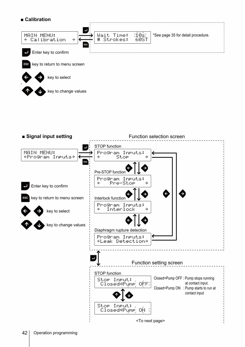
42 Operation programming
*See page 35 for detail procedure.
Enter key to confirm
key to return to menu screen
key to select
key to change values
■ Calibration
STOP function
Pre-STOP function
Interlock function
Diaphragm rupture detection
STOP functionClosed=Pump OFF : Pump stops running
at contact input.Closed=Pump ON : Pump starts to run at
contact input
<To next page>
Enter key to confirm
key to return to menu screen
key to select
key to change values
Function setting screen
Function selection screen■ Signal input setting
43
Operation
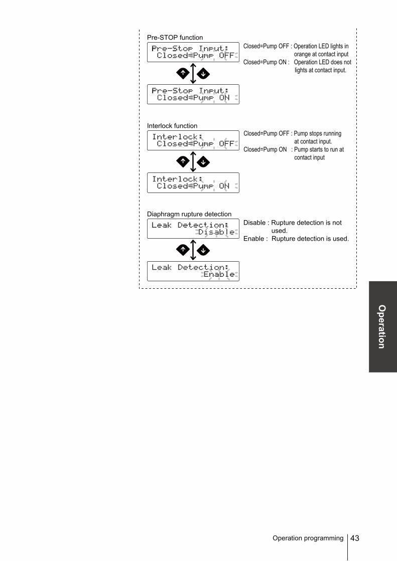
Operation programming
Pre-STOP functionClosed=Pump OFF : Operation LED lights in
orange at contact inputClosed=Pump ON : Operation LED does not
lights at contact input.
Interlock function
Diaphragm rupture detectionDisable : Rupture detection is not
used.Enable : Rupture detection is used.
Closed=Pump OFF : Pump stops running at contact input.
Closed=Pump ON : Pump starts to run at contact input
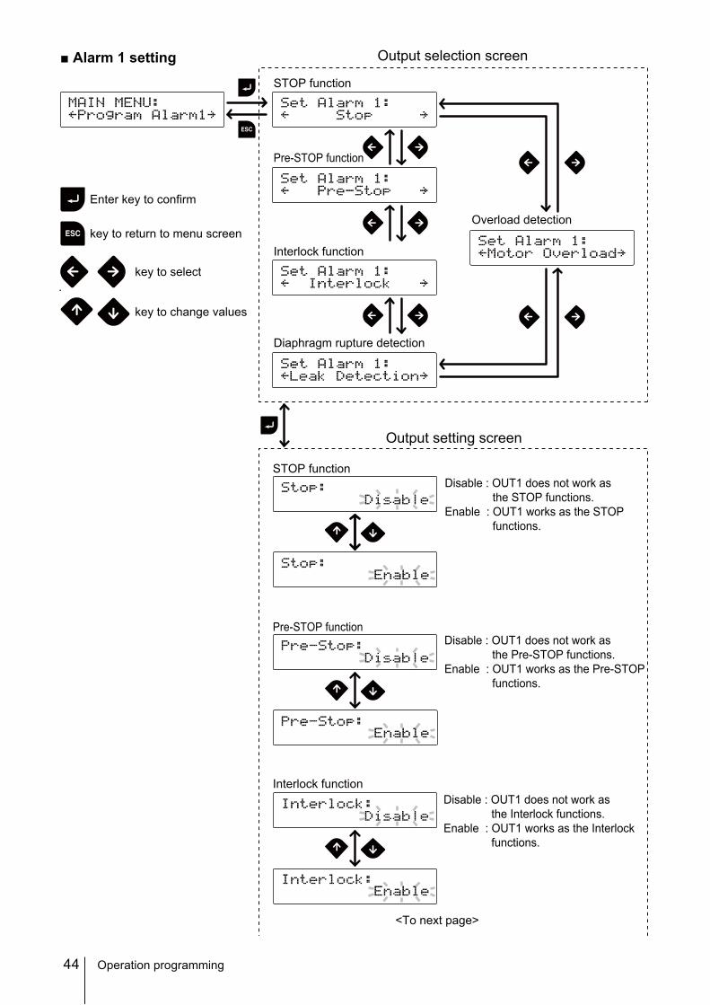
44 Operation programming
Disable : OUT1 does not work asthe STOP functions.
Enable : OUT1 works as the STOPfunctions.
Output setting screen
Output selection screen
STOP function
Pre-STOP function
Interlock function
Diaphragm rupture detection
STOP function
Pre-STOP function
Interlock function
Overload detection
Disable : OUT1 does not work asthe Interlock functions.
Enable : OUT1 works as the Interlockfunctions.
Disable : OUT1 does not work asthe Pre-STOP functions.
Enable : OUT1 works as the Pre-STOPfunctions.
<To next page>
■ Alarm 1 setting
Enter key to confirm
key to return to menu screen
key to select
key to change values
45
Operation
Operation programming
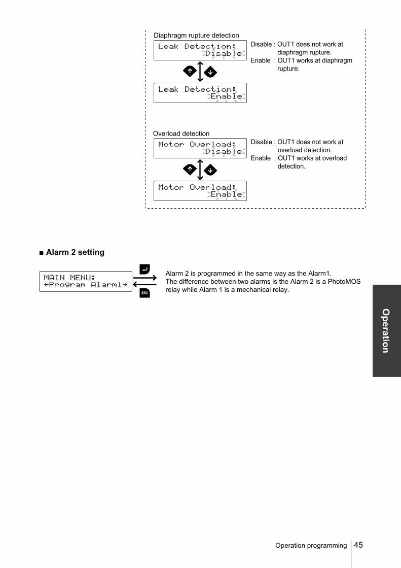
Alarm 2 is programmed in the same way as the Alarm1.The difference between two alarms is the Alarm 2 is a PhotoMOSrelay while Alarm 1 is a mechanical relay.
■ Alarm 2 setting
Diaphragm rupture detection
Overload detection
Disable : OUT1 does not work atdiaphragm rupture.
Enable : OUT1 works at diaphragmrupture.
Disable : OUT1 does not work atoverload detection.
Enable : OUT1 works at overloaddetection.
46
*A selected data will be cleared.*Version information will not be cleared.
Operation programming
Operating time
Total flow volume
Powered-on time
Number of ON/OFF
3 sec Return to a previous screen.
Software version
Data logging screen
Enter key to confirm
key to return to menu
key to select
Press 3 sec to delete data
■ Data logging
47
Operation
Suction speed
AUX speed
Diaphragm position
Anti chattering
Suction speed
AUX speed
Flow rate unit
Set a flow rate.
Other setting screen
Other selection screen
Enter key to confirm
key to return to menu screen
key to select
key to change values
<To next page>
■ Programming of other functions
Operation programming
48 Operation programming
Diaphragm position
MAX OUT Pos. : The diaphragm comes to the top dead point.MAX IN Pos. : The diaphragm comes to the bottom dead point.
Anti chattering
Flow rate unit
Either one of the above indication keeps flashing as long as thediaphragm is at either end. Push the Enter key to return.
49
Operation
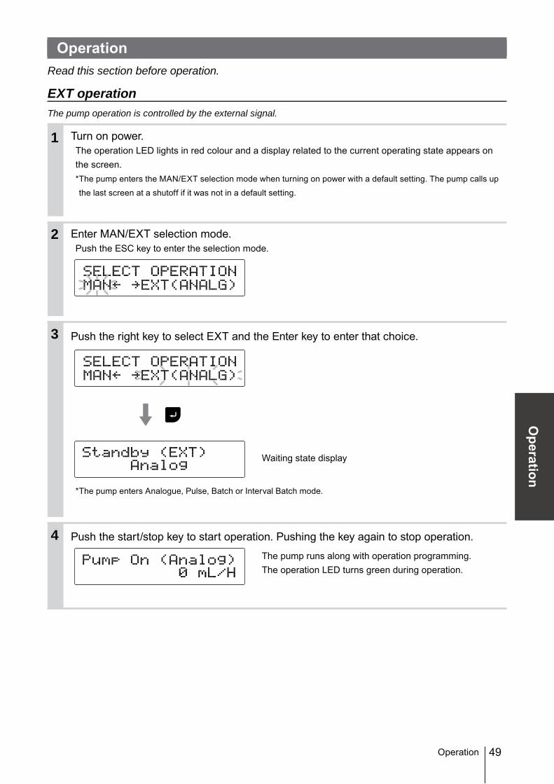
OperationRead this section before operation.
EXT operationThe pump operation is controlled by the external signal.
Turn on power.The operation LED lights in red colour and a display related to the current operating state appears on the screen.* The pump enters the MAN/EXT selection mode when turning on power with a default setting. The pump calls up
the last screen at a shutoff if it was not in a default setting.
Enter MAN/EXT selection mode.Push the ESC key to enter the selection mode.
Push the right key to select EXT and the Enter key to enter that choice.
Waiting state display
*The pump enters Analogue, Pulse, Batch or Interval Batch mode.
Push the start/stop key to start operation. Pushing the key again to stop operation.
The pump runs along with operation programming.The operation LED turns green during operation.
Operation
2
1
3
4
50
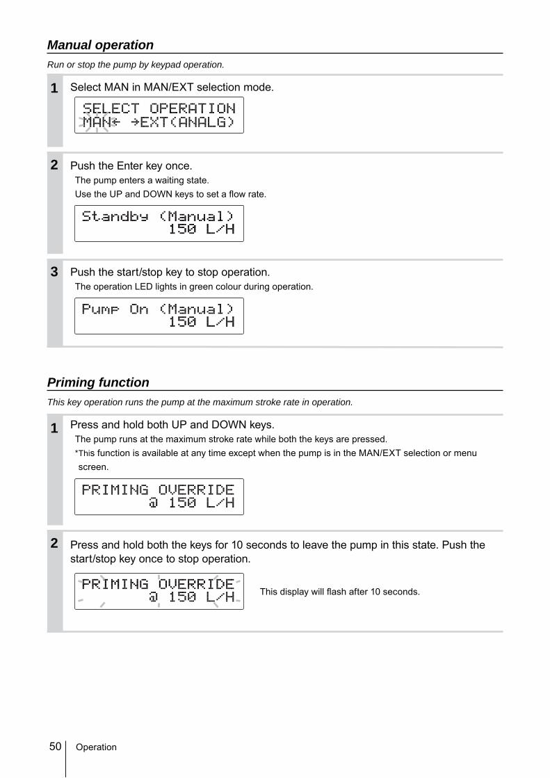
Manual operationRun or stop the pump by keypad operation.
Select MAN in MAN/EXT selection mode.
Push the Enter key once.The pump enters a waiting state. Use the UP and DOWN keys to set a flow rate.
Push the start/stop key to stop operation.The operation LED lights in green colour during operation.
Priming functionThis key operation runs the pump at the maximum stroke rate in operation.
Press and hold both UP and DOWN keys.The pump runs at the maximum stroke rate while both the keys are pressed.* This function is available at any time except when the pump is in the MAN/EXT selection or menu screen.
Press and hold both the keys for 10 seconds to leave the pump in this state. Push the start/stop key once to stop operation.
This display will flash after 10 seconds.
2
1
3
2
1
Operation
51
Maintenance
Maintenance
This section describes troubleshooting, maintenance, wear part replacement, exploded views and specification.
Points to be observedObserve the following points during wiring work.• Observe instructions in this manual for maintenance, inspection, dismantlement and as-
sembly. Do not dismantle the pump beyond the extent of the instructions.• Always wear protective clothing such as an eye protection, chemical resistant gloves, a
mask and a work cap during dismantlement, assembly or maintenance work.• Be sure to turn off power to stop the pump and related devices before work. See below.
Before unplugging the pumpAlways stop the pump by key operation. And wait for three seconds before unplugging the pump. Otherwise, the last key operation to stop the pump may not be put in memory. In this case the pump unintentionally starts to run as powered on, discharging liquid.
NOTE• We do not assure material suitability in a specified application and are not responsible for any failure due to
corrosion or erosion.• Contact your distributor for repair or contact a manufacturer of the host machine which our product is built in.• Be sure to drain chemicals and clean the inside of the pump before return so that a harmful chemical does
not spill out in transit.
Maintenance
52 Troubleshooting
TroubleshootingFirst check the following points. If the following measures do not help remove problems, con-tact your distributor.
■ PumpStates Possible causes Solutions
The pump does not run ( The operation LED does not appear or the screen is blank.).
Power voltage is too low. • Recover the power voltage to a normal level.
• Allowable voltage range: 90-264VACThe pump is not powered. • Check the switch if it is installed.
• Correct wiring.• Replace a breaking wire to new one.
Liquid can not be pumped up.
Air lock in the pump • Expel air. See page 33.Air ingress through suction line. • Reroute piping.An O ring is not fitted to a valve set. • Fit O ring to the valve set.Foreign matters are stuck in the pump head valves.
• Dismantle, inspect and clean the valve. Replace as necessary.
A ball valve is stuck on a valve seat. • Dismantle, inspect and clean the valve. Replace as necessary.
A flow rate fluctuates. Air stays in the pump head. • Expel air. See page 33.Overfeeding occurs. • Mount a back pressure valve to keep a
level of discharge line pressure. Foreign matters are stuck in the pump head valves.
• Dismantle, inspect and clean the valve. Replace as necessary.
Diaphragm is broken. • Replace diaphragm. See page 57.Pressure fluctuates at an injection point.
• Maintain a pressure constant at an injec-tion point by optimizing piping or by relo-cating the point.
Liquid leaks. A fitting is loose. • Tighten the nut to fix the fitting.Loose fit of the pump head. • Retighten the pump head. See page 32.An O ring is not fitted to a valve set. • Fit O ring to the valve set. See page 56.Diaphragm is broken.A leak from the drain port (Vent hole)
• Replace diaphragm. See page 57.
Discharge pressure is too high. • Check that a discharge line is not closed.• Check if piping is not clogged.
53
Maintenance
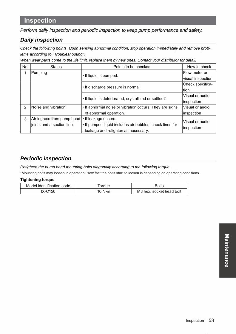
InspectionPerform daily inspection and periodic inspection to keep pump performance and safety.
Daily inspectionCheck the following points. Upon sensing abnormal condition, stop operation immediately and remove prob-lems according to "Troubleshooting".When wear parts come to the life limit, replace them by new ones. Contact your distributor for detail.No. States Points to be checked How to check1 Pumping
• If liquid is pumped.Flow meter or visual inspection
• If discharge pressure is normal.Check specifica-tion.
• If liquid is deteriorated, crystallized or settled?Visual or audio inspection
2 Noise and vibration • If abnormal noise or vibration occurs. They are signs of abnormal operation.
Visual or audio inspection
3 Air ingress from pump head joints and a suction line
• If leakage occurs.• If pumped liquid includes air bubbles, check lines for
leakage and retighten as necessary.
Visual or audio inspection
Periodic inspectionRetighten the pump head mounting bolts diagonally according to the following torque.* Mounting bolts may loosen in operation. How fast the bolts start to loosen is depending on operating conditions.
Wear parts replacementTo run the pump for a long period, wear parts need to be replaced periodically.It is recommended that the following parts are always stocked for immediate replacement. Contact your distributor for detail.
Precautions• When dismantling the pump, pay attention to the residual liquid in the pump.• Rinse wet ends thoroughly with tap water.• Each time the pump head is dismantled, replace the diaphragm and valve sets with new
ones.
Wear part listParts # of parts Estimated life
Valve set(TC type) 2 sets
O ring (7&8)4000 hours
Valve seat (4)8000 hours
Valve (2)Seat holder (5&6)
Valve guide (3)24000 hours
Diaphragm 1 4000 hours
* Wear part duration varies with the pressure, temperature and characteristics of the liquid.* The estimated life is calculated based on pumping clean water at ambient temperature.
7
3
24
8
5
7
6
30
Discharge side
Suction side
55
Maintenance
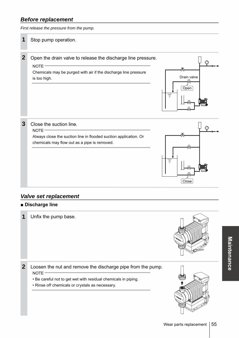
Before replacementFirst release the pressure from the pump.
Stop pump operation.
Open the drain valve to release the discharge line pressure.
NOTEChemicals may be purged with air if the discharge line pressure is too high.
Close the suction line.NOTEAlways close the suction line in flooded suction application. Or chemicals may flow out as a pipe is removed.
Valve set replacement■ Discharge line
Unfix the pump base.
Loosen the nut and remove the discharge pipe from the pump.NOTE• Be careful not to get wet with residual chemicals in piping.• Rinse off chemicals or crystals as necessary.
Wear parts replacement
Open
Close
2
1
3
2
1
Drain valve
56 Wear parts replacement
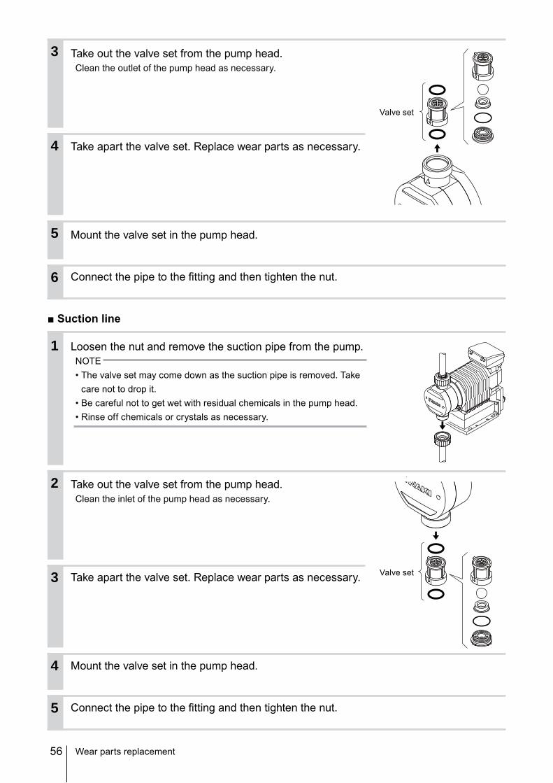
Take out the valve set from the pump head.Clean the outlet of the pump head as necessary.
Take apart the valve set. Replace wear parts as necessary.
Mount the valve set in the pump head.
Connect the pipe to the fitting and then tighten the nut.
■ Suction line
Loosen the nut and remove the suction pipe from the pump.NOTE• The valve set may come down as the suction pipe is removed. Take
care not to drop it.• Be careful not to get wet with residual chemicals in the pump head.• Rinse off chemicals or crystals as necessary.
Take out the valve set from the pump head.Clean the inlet of the pump head as necessary.
Take apart the valve set. Replace wear parts as necessary.
Mount the valve set in the pump head.
Connect the pipe to the fitting and then tighten the nut.
Loosen the nuts and disconnect piping.NOTE• The valve set may come down as the suction pipe is removed.
Take care not to drop it.• Be careful not to get wet with residual chemicals in the pump head
or discharge piping.
Remove the bolt cover by a hexagon wrench.
Use an adjustable wrench or spanner to remove 8 pump head fixing bolts and detach the pump head with a rein-forcing plate.
Rotate and remove the diaphragm with the retainer.
Wear parts replacement
2
1
3
4
Hexagon wrench
58 Wear parts replacement
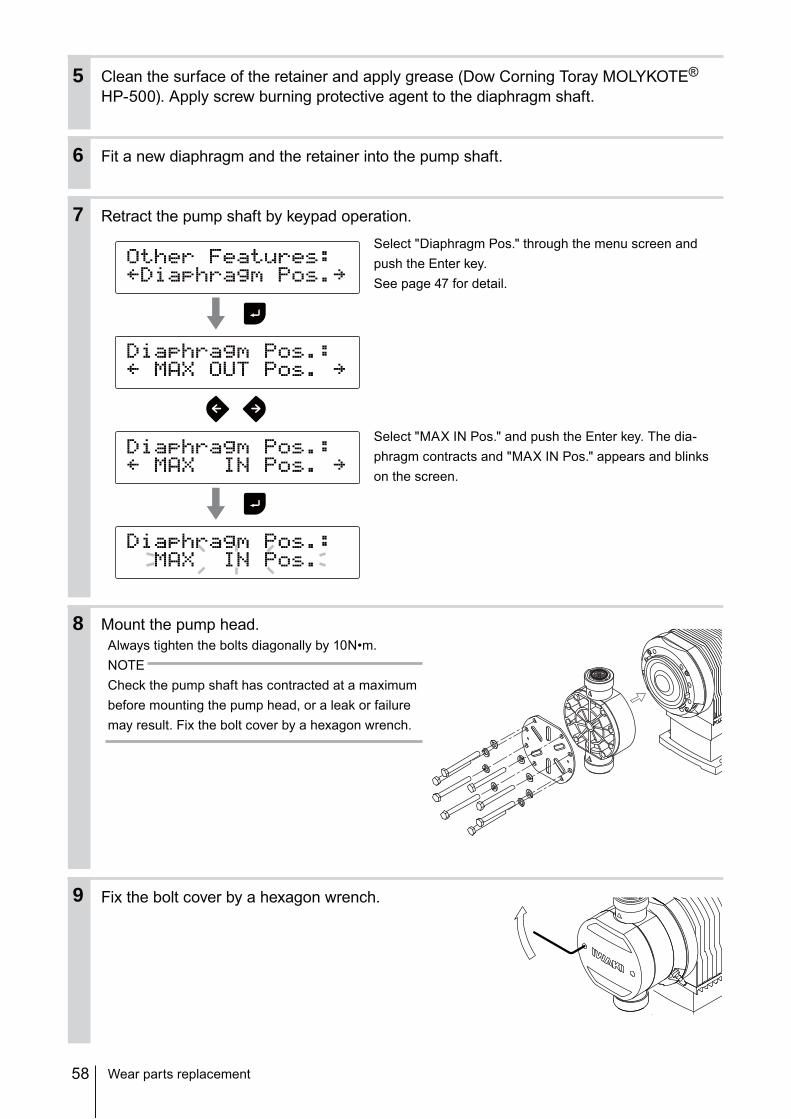
Clean the surface of the retainer and apply grease (Dow Corning Toray MOLYKOTE® HP-500). Apply screw burning protective agent to the diaphragm shaft.
Fit a new diaphragm and the retainer into the pump shaft.
Retract the pump shaft by keypad operation.
Select "Diaphragm Pos." through the menu screen and push the Enter key.See page 47 for detail.
Select "MAX IN Pos." and push the Enter key. The dia-phragm contracts and "MAX IN Pos." appears and blinks on the screen.
Mount the pump head.Always tighten the bolts diagonally by 10N•m.NOTECheck the pump shaft has contracted at a maximum before mounting the pump head, or a leak or failure may result. Fix the bolt cover by a hexagon wrench.
Fix the bolt cover by a hexagon wrench.
6
5
7
8
9
59
Maintenance
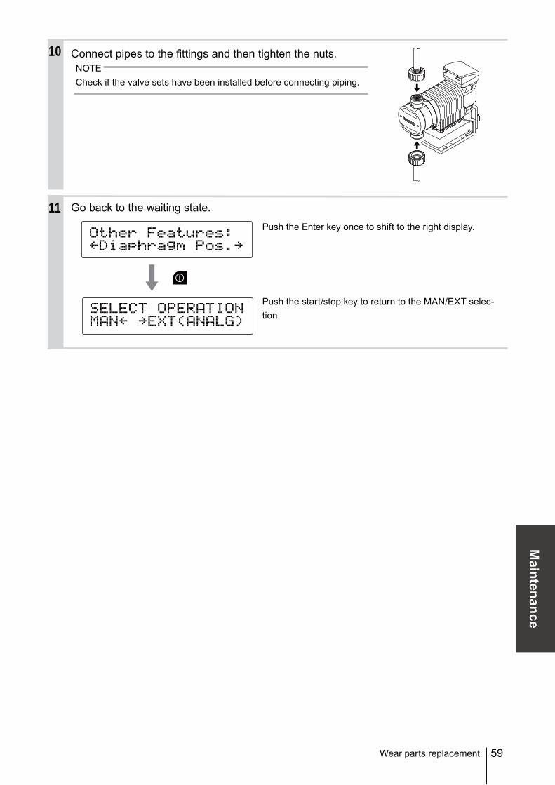
Connect pipes to the fittings and then tighten the nuts.NOTECheck if the valve sets have been installed before connecting piping.
Go back to the waiting state.
Push the Enter key once to shift to the right display.
Push the start/stop key to return to the MAN/EXT selec-tion.
Wear parts replacement
10
11
60
Exploded view
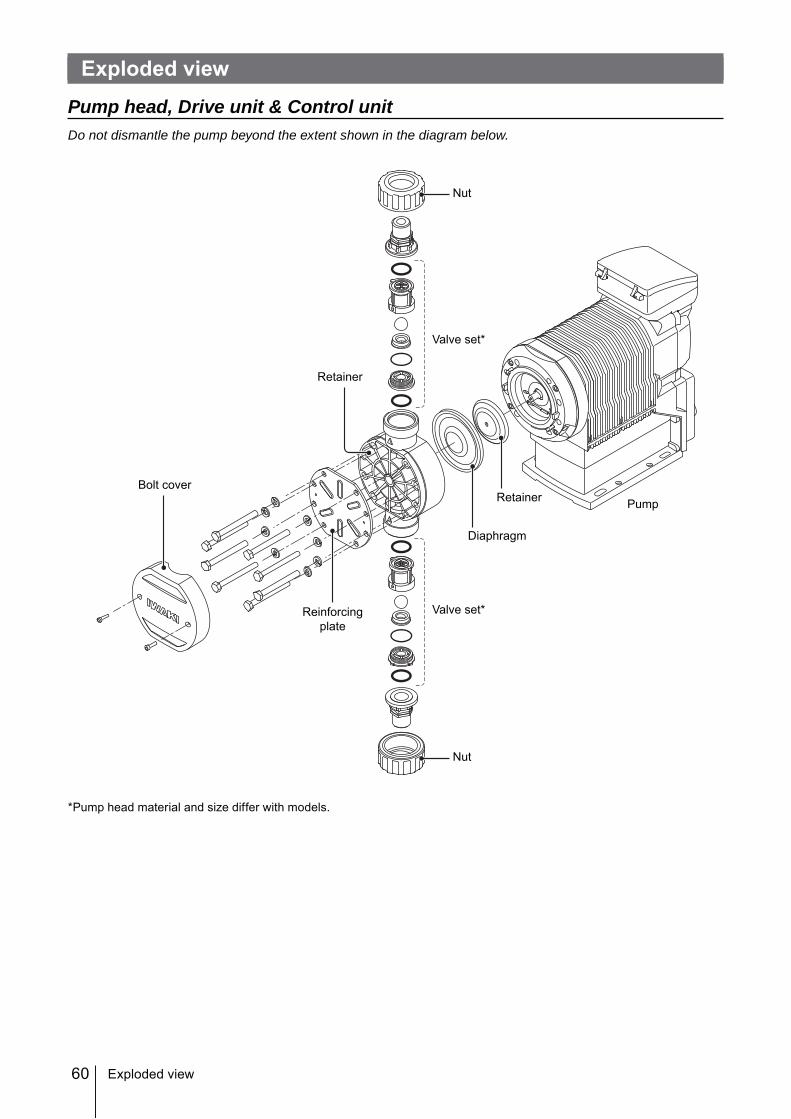
Pump head, Drive unit & Control unitDo not dismantle the pump beyond the extent shown in the diagram below.
*Pump head material and size differ with models.
Exploded view
PumpRetainer
Diaphragm
Bolt cover
Reinforcingplate
Valve set*
Valve set*
Retainer
Nut
Nut
61
Maintenance
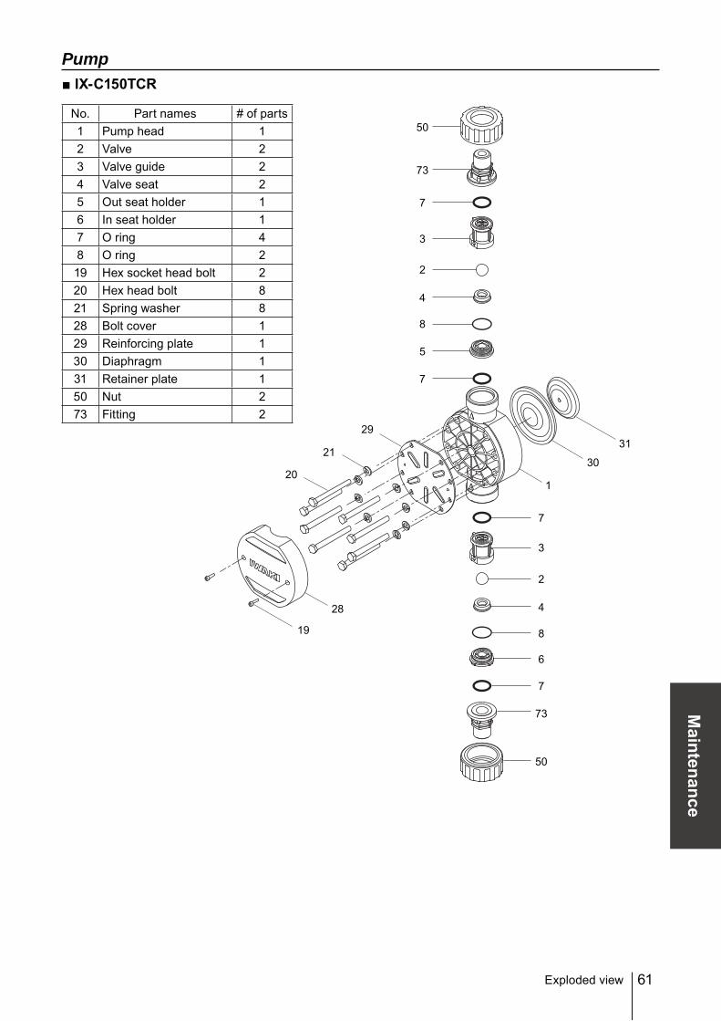
Pump■ IX-C150TCR
No. Part names # of parts1 Pump head 12 Valve 23 Valve guide 24 Valve seat 25 Out seat holder 16 In seat holder 17 O ring 48 O ring 219 Hex socket head bolt 220 Hex head bolt 821 Spring washer 828 Bolt cover 129 Reinforcing plate 130 Diaphragm 131 Retainer plate 150 Nut 273 Fitting 2
Exploded view
1
30
31
19
28
20
21
29
50
50
73
7
3
2
4
8
5
7
73
7
7
6
3
2
4
8
62
■ IX-C150TCF
No. Part names # of parts1 Pump head 12 Valve 23 Valve guide 24 Valve seat 25 Out seat holder 16 In seat holder 17 O ring 48 O ring 219 Hex socket head bolt 220 Hex head bolt 821 Spring washer 828 Bolt cover 129 Reinforcing plate 130 Diaphragm 131 Retainer plate 145 Flange unit 2
Exploded view
1
30
31
19
28
20
21
29
45
45
7
3
2
4
8
5
7
7
7
6
3
2
4
8
63
Specification
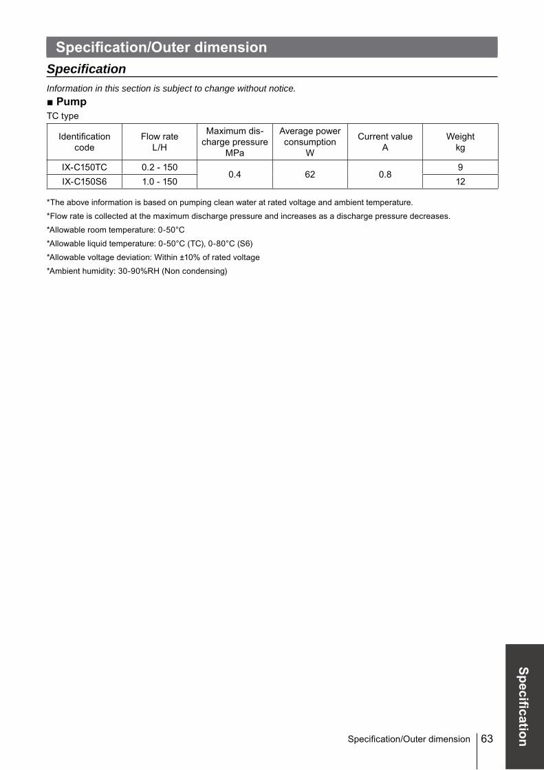
Specification/Outer dimensionSpecificationInformation in this section is subject to change without notice.■ PumpTC type
Identification code
Flow rateL/H
Maximum dis-charge pressure
MPa
Average power consumption
W
Current valueA
Weightkg
IX-C150TC 0.2 - 1500.4 62 0.8
9IX-C150S6 1.0 - 150 12
*The above information is based on pumping clean water at rated voltage and ambient temperature.
*Flow rate is collected at the maximum discharge pressure and increases as a discharge pressure decreases.
*Allowable voltage deviation: Within ±10% of rated voltage
*Ambient humidity: 30-90%RH (Non condensing)
Specification/Outer dimension
64
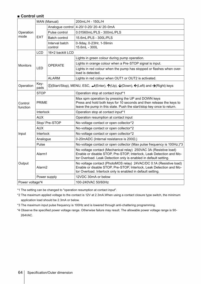
■ Control unit
Operation mode
MAN (Manual) 200mL/H - 150L/H
EXT
Analogue control 4-20/ 0-20/ 20-4/ 20-0mAPulse control 0.01560mL/PLS - 300mL/PLSBatch control 15.6mL/PLS - 300L/PLSInterval batch control
0-9day, 0-23Hr, 1-59min15.6mL - 300L
Monitors
LCD 16×2 backlit LCD
LEDOPERATE
Lights in green colour during pump operation.Lights in orange colour when a Pre-STOP signal is input.Lights in red colour when the pump has stopped or flashes when over-load is detected.
ALARM Lights in red colour when OUT1 or OUT2 is activated.
PRIMEMax spm operation by pressing the UP and DOWN keysPress and hold both keys for 10 seconds and then release the keys to leave the pump in this state. Push the start/stop key once to return.
Interlock Operation stop at contact input*1AUX Operation resumption at contact input
Input
Stop/ Pre-STOP No-voltage contact or open collector*2AUX No-voltage contact or open collector*2Interlock No-voltage contact or open collector*2Analogue 0-20mADC (Internal resistance is 200Ω.)Pulse No-voltage contact or open collector (Max pulse frequency is 100Hz.)*3
Output
Alarm1No voltage contact (Mechanical relay) 250VAC 3A (Resistive load)Enable or disable STOP, Pre-STOP, Interlock, Leak Detection and Mo-tor Overload. Leak Detection only is enabled in default setting.
Alarm2No voltage contact (PhotoMOS relay) 24VAC/DC 0.1A (Resistive load)Enable or disable STOP, Pre-STOP, Interlock, Leak Detection and Mo-tor Overload. Interlock only is enabled in default setting.
Power supply 12VDC 30mA or belowPower voltage*4 100-240VAC 50/60Hz
*1 The setting can be changed to "operation resumption at contact input".
*2 The maximum applied voltage to the contact is 12V at 2.3mA.When using a contact closure type switch, the minimum
application load should be 2.3mA or below.
*3 The maximum input pulse frequency is 100Hz and is lowered through anti-chattering programming.
*4 Observe the specified power voltage range. Otherwise failure may result. The allowable power voltage range is 90-
264VAC.
Specification/Outer dimension
65
Specification
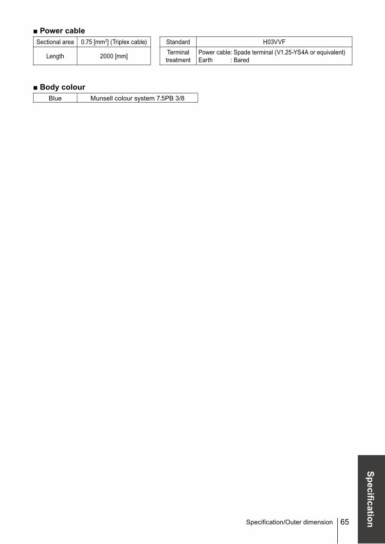
■ Power cableSectional area 0.75 [mm2] (Triplex cable) Standard H03VVF
Length 2000 [mm] Terminal treatment
Power cable: Spade terminal (V1.25-YS4A or equivalent)Earth : Bared