This slide set is distributed to support students of the University of Stuttgart who attend the IPNA lectureduring summer term 2004. All other use requires written permission by Joachim Charzinski.
1. Introduction 1-11.1 Overview of the lecture 1-61.2 Internet History 1-261.3 IP Standardisation 1-461.4 Networking Basics Refresher 1-551.4.1 Reference Model 1-561.4.2 Circuit Switching and Packet Switching 1-591.4.3 Local Area Networks 1-651.4.4 Network Elements 1-76
Questions 1-94
2. Network Layer et. al. 2-12.1 Internet Reference Model 2-32.2 IP 2-142.2.1 IP Packets 2-192.2.2 Addressing 2-322.2.3 Fragmentation 2-432.3 ICMP 2-502.4 ARP 2-622.5 Routing 2-682.5.1 Principle 2-692.5.2 Algorithms 2-812.5.3 Protocols 2-862.6 UDP 2-93
Questions 2-99
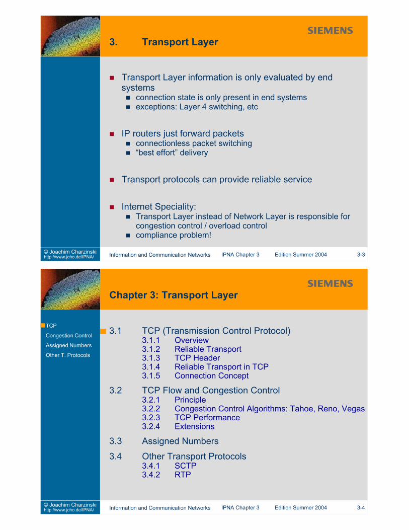
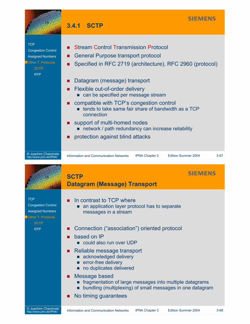
3. Transport Layer 3-13.1 TCP (Transmission Control Protocol) 3-53.1.1 Overview 3-63.1.2 Reliable Transport 3-83.1.3 TCP Header 3-133.1.4 Reliable Transport in TCP 3-223.1.5 Connection Concept 3-283.2 TCP Flow and Congestion Control 3-383.2.1 Principle 3-413.2.2 Congestion Control Algorithms: Tahoe, Reno, Vegas 3-473.2.3 TCP Performance 3-563.2.4 Extensions 3-613.3 Assigned Numbers 3-623.4 Other Transport Protocols 3-663.4.1 SCTP 3-673.4.2 RTP 3-71
Questions 3-76
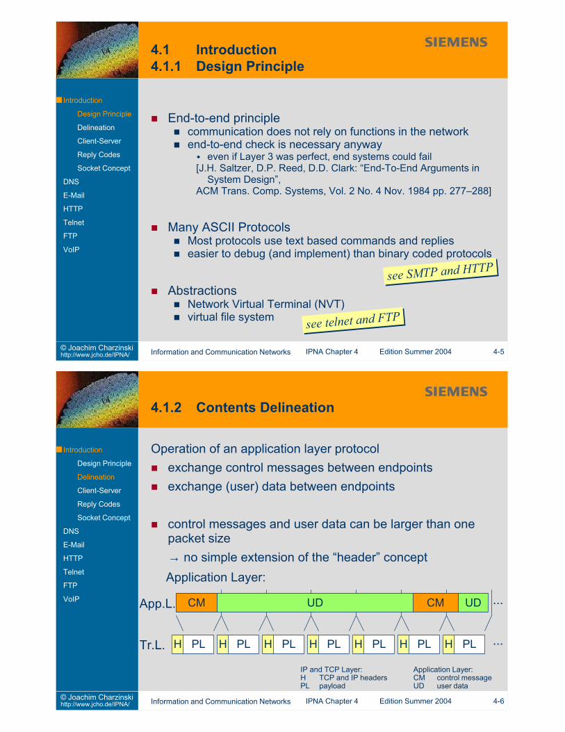
IPNA – IP based Networks and ApplicationsTable of Contents (2) 2004 Edition4. Applications and Application Layer Protocols 4-14.1 Introduction 4-54.1.1 Design Principles 4-54.1.2 Contents Delineation 4-64.1.3 Client-Server Paradigm 4-94.1.4 Reply Codes 4-114.1.5 Socket Concept 4-154.2 DNS 4-204.3 E-Mail 4-284.3.1 SMTP 4-324.3.2 MIME 4-374.3.3 POP3 4-394.3.4 IMAP 4-424.4 HTTP 4-434.5 Telnet 4-554.6 FTP 4-624.7 VoIP 4-674.7.1 Packetized Voice 4-694.7.1 H.323 4-714.7.2 SIP 4-78
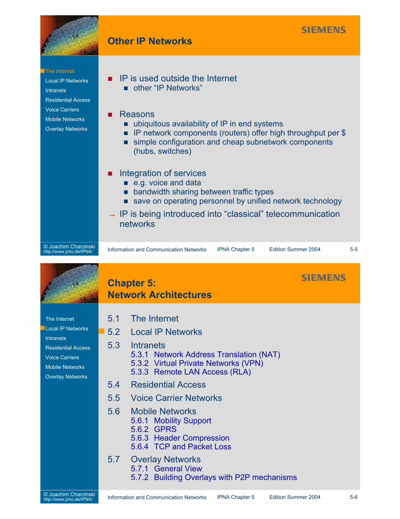
5. Network Architectures 5-15.1 The Internet 5-45.2 Local IP Networks 5-65.3 Intranets 5-135.3.1 Network Address Translation (NAT) 5-155.3.2 Virtual Private Networks (VPN) 5-165.3.3 Remote LAN Access (RLA) 5-175.4 Residential Access 5-185.5 Voice Carrier Networks 5-225.6 Mobile Networks 5-255.6.1 Mobility Support 5-265.6.2 GPRS 5-295.6.3 Header Compression 5-305.6.4 TCP and Packet Loss 5-325.7 Overlay Networks 5-345.7.1 General View 5-355.7.2 Building Overlays with P2P Mechanisms 5-37
Questions 5-39
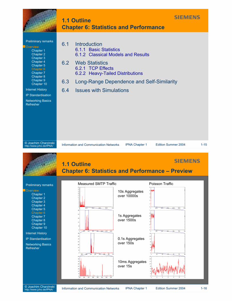
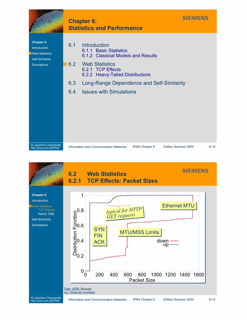
6. Statistics and Performance 6-16.1 Introduction 6-46.1.1 Basic Statistics 6-46.1.2 Classical Models and Results 6-106.2 Web Statistics 6-136.2.1 TCP Effects 6-146.2.2 Heavy-Tailed Distributions 6-176.3 Long-Range Dependence and Self-Similarity 6-216.4 Issues with Simulations 6-27
Questions 6-32
IPNA – IP based Networks and ApplicationsTable of Contents (3) 2004 Edition7. Quality of Service 7-17.1 What is Quality of Service? 7-47.2 Best Effort Service 7-97.3 Differentiated Services 7-117.4 Integrated Services 7-147.5 MPLS 7-167.6 Service Level Agreements 7-22
This slide set is distributed to support students of the University of Stuttgart who attend the IPNA lectureduring summer term 2004. All other use requires written permission by Joachim Charzinski.
“homework”preparation for next lecturesimple tasks to give you a “hands-on” feeling for the coursematerialmixture of fun and workno “official” solutions
1. Introduction2. Network Layer (et al.)3. Transport Layer4. Applications and Application Layer Protocols5. Network Architectures6. Statistics and Performance7. Quality of Service8. Network Management9. Security
Minimum conversation between client (C) and server (S)
S: 220 host-a.net readyC: HELO host-b.eduS: 250 host-a.netC: MAIL FROM:<[email protected]>S: 250 OKC: RCPT TO:<[email protected]>S: 250 OKC: DATAS: 354 Start mail input; end with <CR><LF>.<CR><LF>C: Hi, this is my test mail to you allC: which extends over a few linesC: ...C: <CR><LF>.<CR><LF>S: 250 OKC: QUITS: 221 mailserver.mynet closing connection. Thanks for your message.
S: 220 host-a.net readyC: HELO host-b.eduS: 250 host-a.netC: MAIL FROM:<[email protected]>S: 250 OKC: RCPT TO:<[email protected]>S: 250 OKC: DATAS: 354 Start mail input; end with <CR><LF>.<CR><LF>C: Hi, this is my test mail to you allC: which extends over a few linesC: ...C: <CR><LF>.<CR><LF>S: 250 OKC: QUITS: 221 mailserver.mynet closing connection. Thanks for your message.
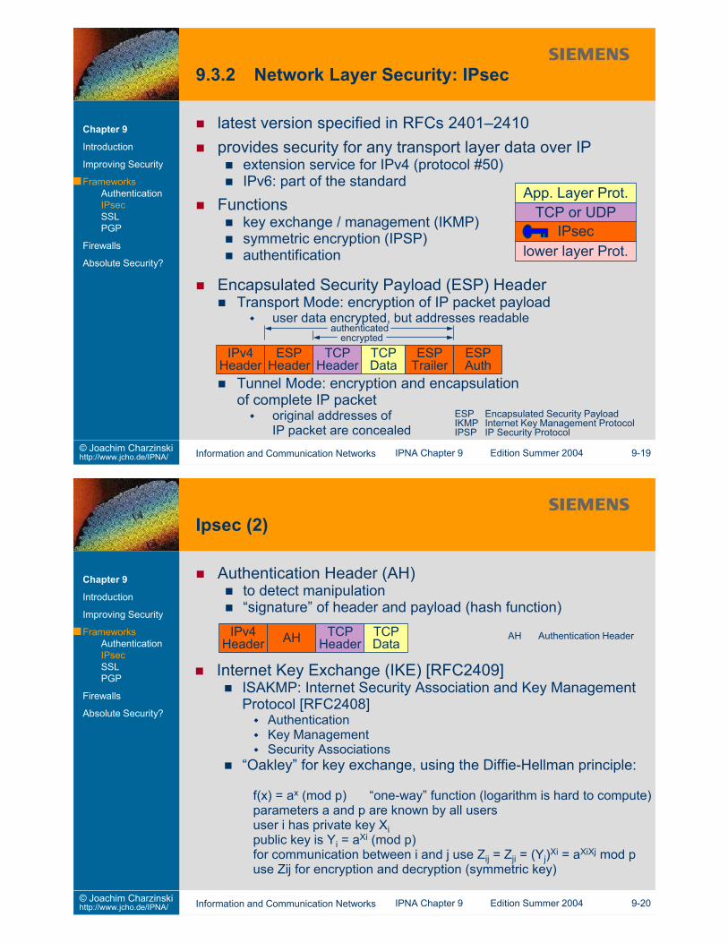
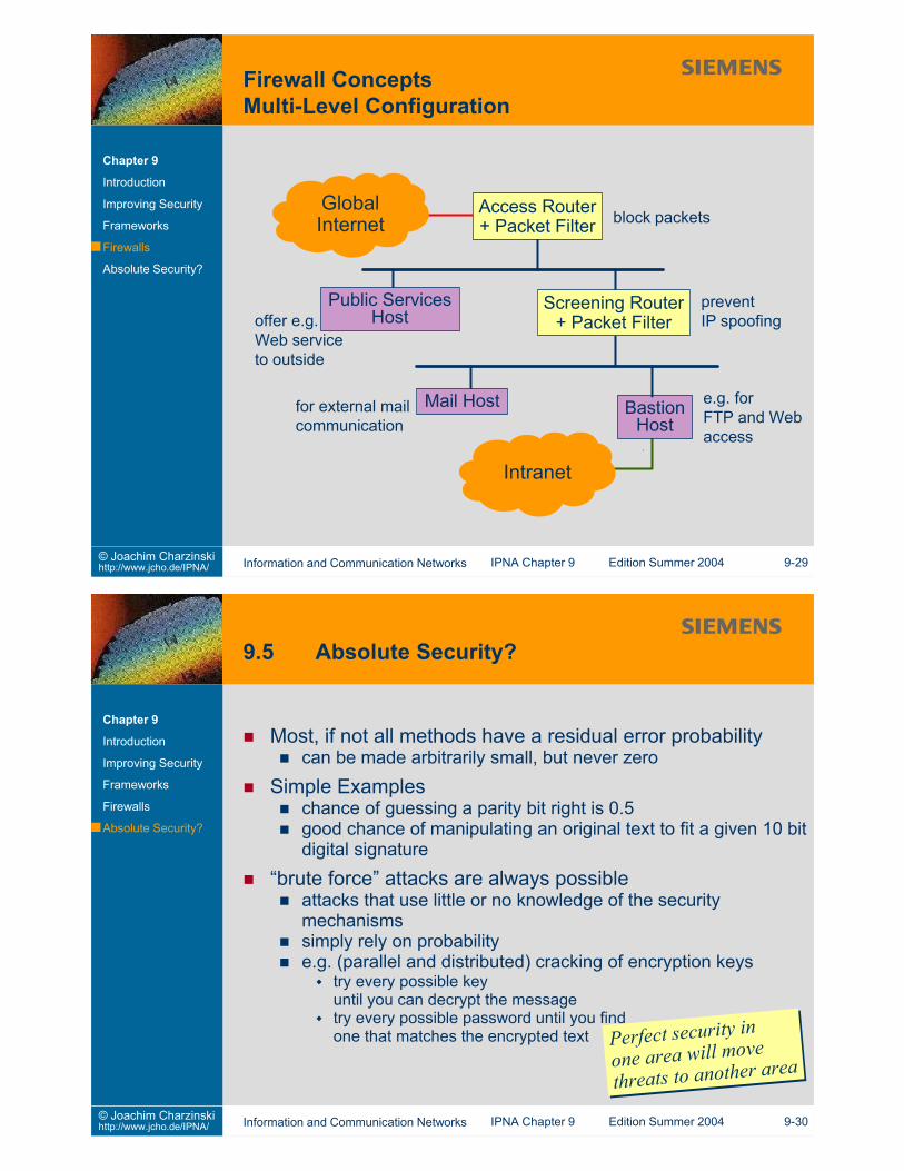
Secure a whole enterprise networkCommon point of trust
reduces effort in securing many computersreduces risk of a misconfigured computer compromising others’securityonly one system to verify and observeonly few services need to go across
GlobalInternet
(insecure)
Intranet(protected)
FirewallFirewall
selected servicescan pass throughselected servicescan pass through
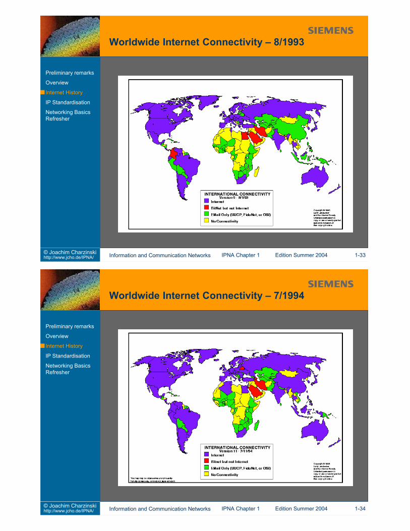
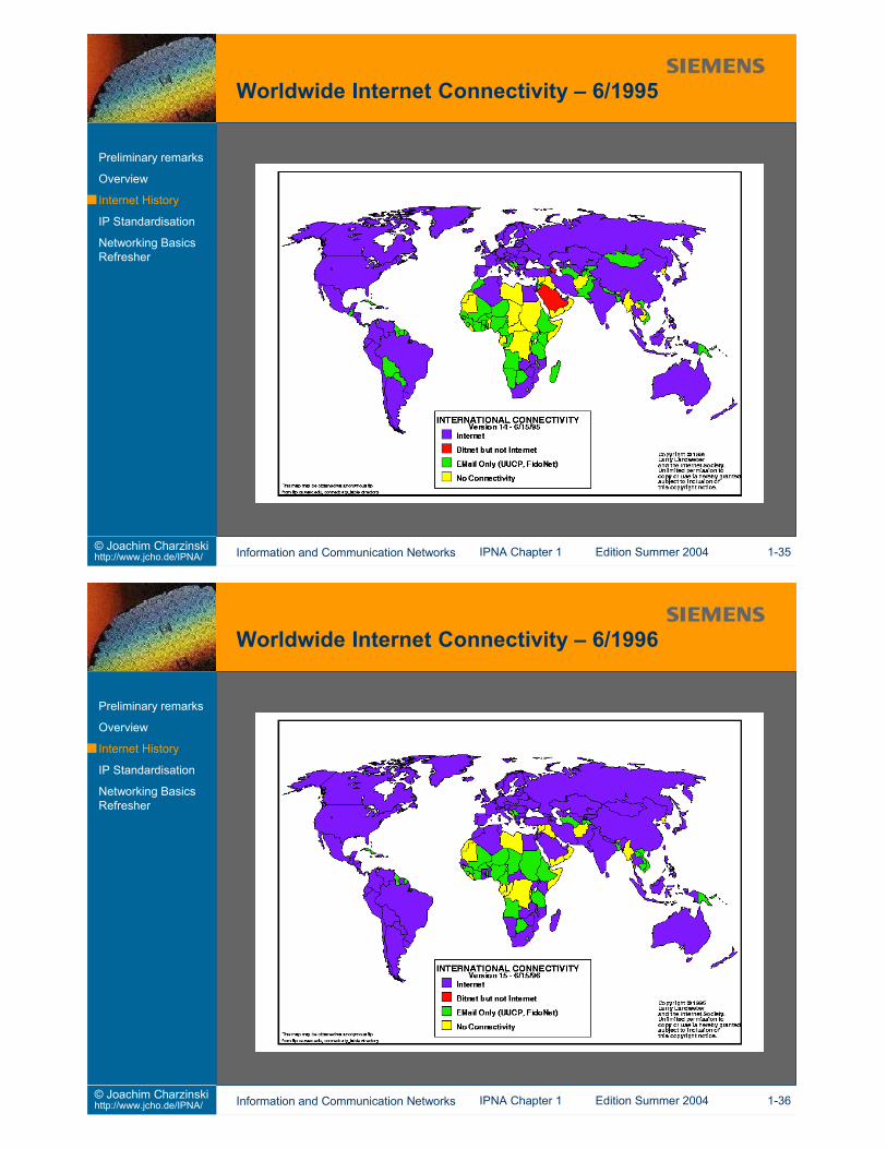
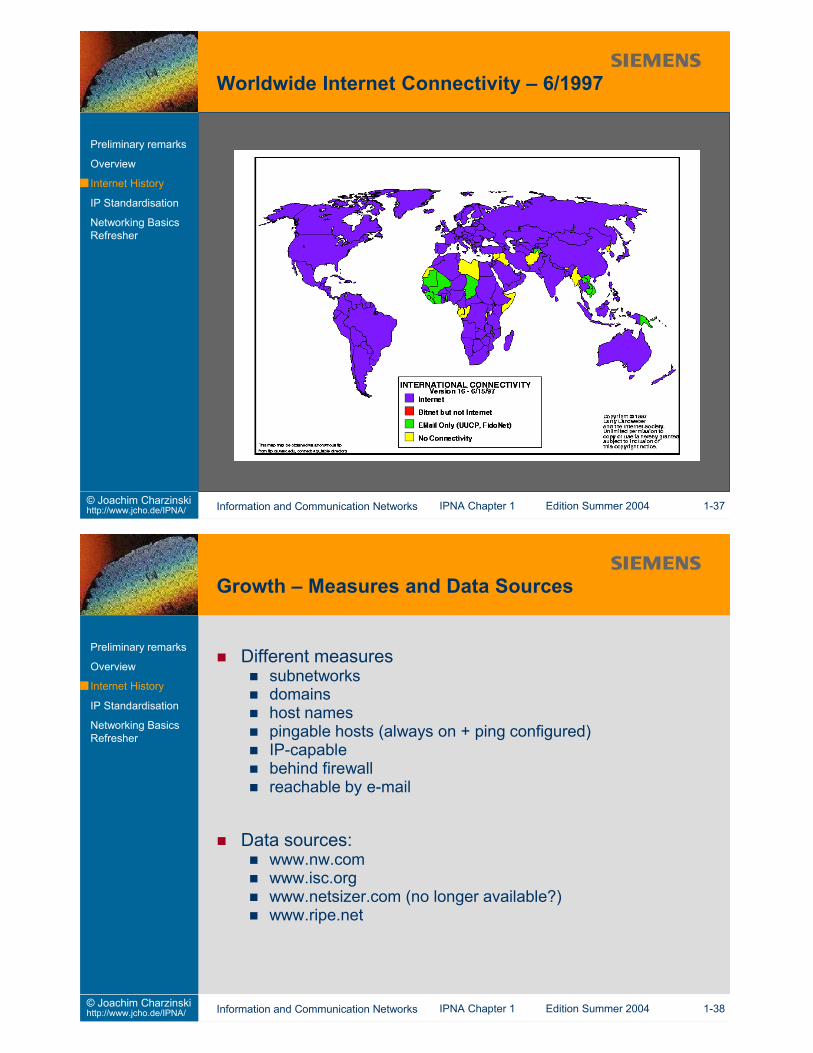
1960s: studies of packet switchingearly 1969: Arpanet contract to BBNDec. 1969: four node network between UCLA, UCSB andUtah4 IMPs (Interface Message Processor)funded by US ARPA (defense) advance research projectsagency (for academia and US military)early inclusion of wireless (ALOHA) and satellite links1973: first international connections1979: around 100 nodes
1980-1983: Introduction of TCP and IPTCP/IP popular on Unix machines
communication protocols and utilities for remote work1984: Domain Name System1986: NSFNET (US national science foundation)1989: 100000 nodes1989: first Web proposal (Tim Berners-Lee, Robert Cailliau)1991: gopher1992: MBONE (multicast for audio and video)1993: NCSA Mosaic (first widely used Web browser)1994: Internet known in public (press, adverts, ISPs)1995: end of the NSFnet backboneNext Generation research networks
Internet2, Canarie (1993), ...Everything over IP, IP over everything
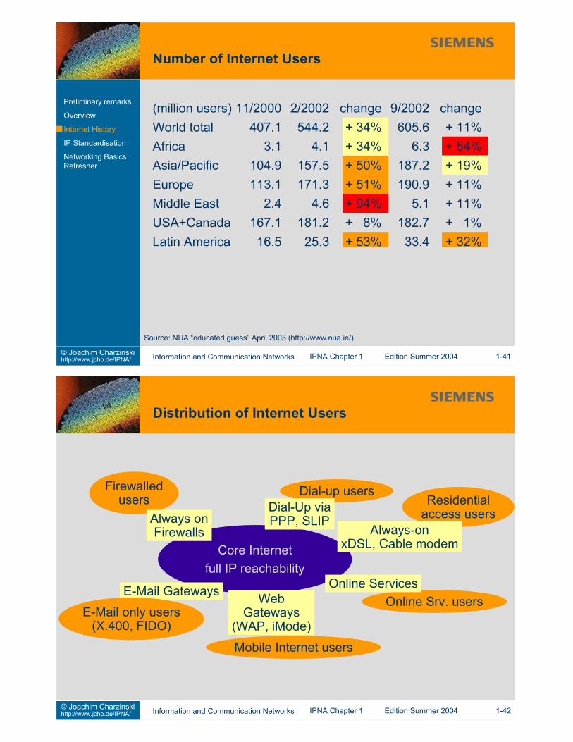
No. Most Hosts Most Largest Fastestper Capita Hosts Domains Growing
1 USA USA com Colombia2 Finland Japan net Ukraine3 Iceland Canada edu Czechia4 Canada UK jp Singapore5 Sweden Germany ca Sweden6 Norway Italy uk Belgium7 New Zealand Australia it South Africa8 Netherlands Netherlands de Argentina9 Hong Kong Taiwan us Spain10 Australia France mil Uruguay
Source:Telcordia Netsizer (http://www.netsizer.com/) on April 21, 2001
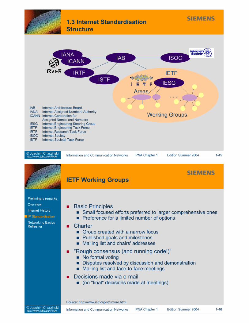
IAB Internet Architecture BoardIANA Internet Assigned Numbers AuthorityICANN Internet Corporation for
Assigned Names and NumbersIESG Internet Engineering Steering GroupIETF Internet Engineering Task ForceIRTF Internet Research Task ForceISOC Internet SocietyISTF Internet Societal Task Force
Active IRTF Research GroupsAnti-Spam*Authentication Authorisation Accounting ArchitectureCrypto Forum*Delay-Tolerant Networking*End-to-EndGroup Security*Internet Measurement*IP Mobility Optimizations*Network ManagementPeer-to-Peer*RoutingServices Management
"Historical" IRTF Research GroupsBuilding Differentiated ServicesInformation Infrastructure Arch.Digital Rights ManagementInternet Resource DiscoveryInterplanetary Internet
Preliminary remarks
Overview
Internet History
IP Standardisation
Networking BasicsRefresher
NameSpacePrivacy and SecurityReliable MulticastSecure MulticastSearchable Resource Names
Internet DraftsWorking documents (works in progress)No status of any kind, not archived, deleted after 6 monthsAnnounced and disseminated by IETF Secretariat
RFCs (Requests for Comment), since 1969Archival document series of the IABNot all RFCs are standards-trackEdited, announced, and disseminated by RFC Editor
Proposed StandardComplete, credible specificationDemonstrated utilityAt least 6 months, no longer than 2 years, then either elevated,depreciated, or recycled
Draft StandardMultiple, independent, interoperable implementationsLimited operational experience - works wellAt least 4 months, no longer than 2 years, then either elevated,depreciated, recycled, or back to Proposed
StandardDemonstrated operational stability"The real thing"Can stay forever, or can be depreciated to Historic (newversions must start over from the beginning)
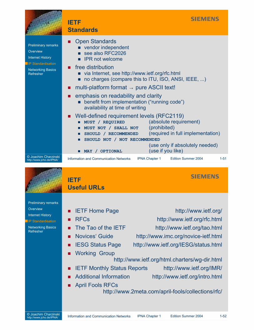
Open Standardsvendor independentsee also RFC2026IPR not welcome
free distributionvia Internet, see http://www.ietf.org/rfc.htmlno charges (compare this to ITU, ISO, ANSI, IEEE, ...)
multi-platform format → pure ASCII text!emphasis on readability and clarity
benefit from implementation (“running code”)availability at time of writing
Well-defined requirement levels (RFC2119)MUST / REQUIRED (absolute requirement)MUST NOT / SHALL NOT (prohibited)SHOULD / RECOMMENDED (required in full implementation)SHOULD NOT / NOT RECOMMENDED
(use only if absolutely needed)MAY / OPTIONAL (use if you like)
IETF Home Page http://www.ietf.org/RFCs http://www.ietf.org/rfc.htmlThe Tao of the IETF http://www.ietf.org/tao.htmlNovices‘ Guide http://www.imc.org/novice-ietf.htmlIESG Status Page http://www.ietf.org/IESG/status.htmlWorking Group
http://www.ietf.org/html.charters/wg-dir.htmlIETF Monthly Status Reports http://www.ietf.org/IMR/Additional Information http://www.ietf.org/intro.htmlApril Fools RFCs
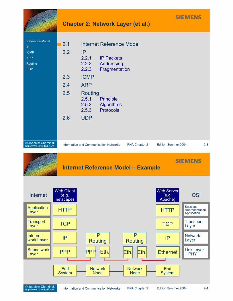
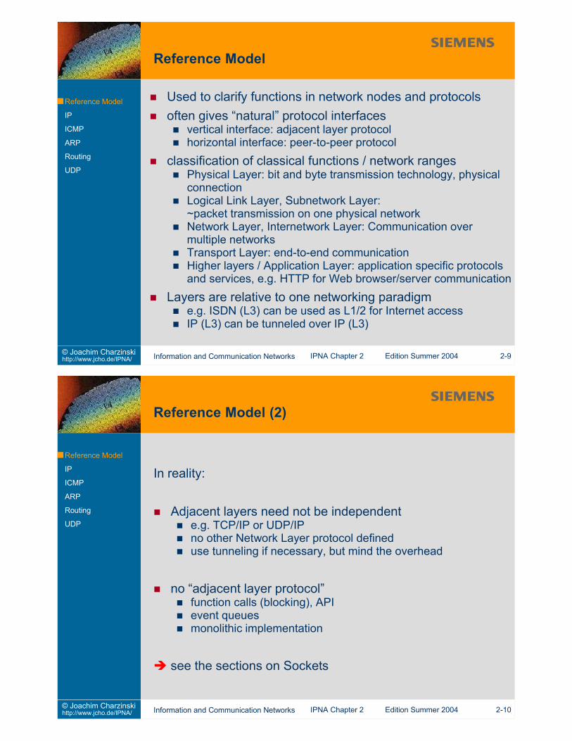
classification of classical functions / network rangesPhysical Layer: bit and byte transmission technology, physicalconnectionLogical Link Layer, Subnetwork Layer:~packet transmission on one physical networkNetwork Layer, Internetwork Layer: Communication over multiplenetworksTransport Layer: end-to-end communicationHigher layers / Application Layer: application specific protocolsand services, e.g. HTTP for Web browser/server communication
Layers are relative to one networking paradigme.g. ISDN (L3) can be used as L1/2 for Internet accessIP (L3) can be tunneled over IP (L3)
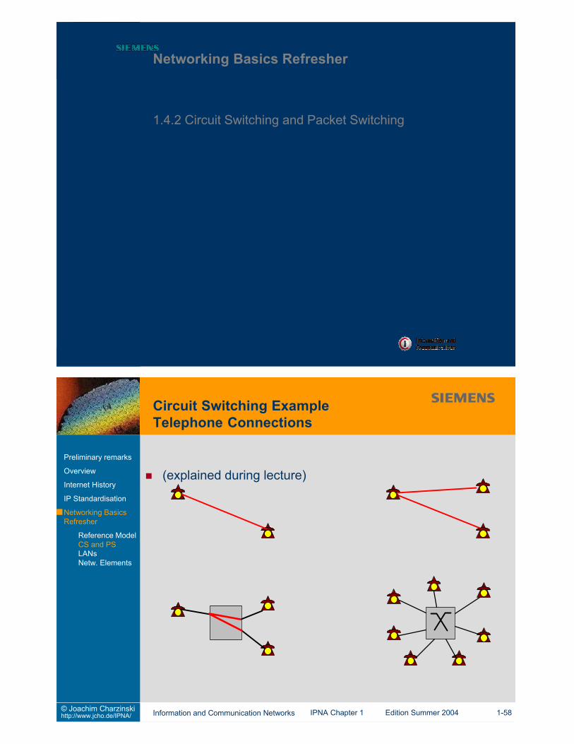
A circuit can be ...a physical linea time slot in a frame in a TDM systema carrier frequency in an FDM systema wavelength in a WDM systema code in a CDMA system
A connection - during its existence - uses one circuit... or a selection of circuits in parallel (multichannel switching)
connection set-upfind path through network and through switches towardsdestinationestablish path
communiationsend fixed data rate into the connectionrelease connection after use
Send packets of datainstead of a fixed bit or byte rateidle time between packets can be used by othercommunication relationsvariable data rate is possibleconnectionless (CL) or connection oriented (CO) modes
Connection establishment before data transmissionrouting performed only for connection establishmentdata transmitted along established patdata packets only carry connection identifierfor packet switching: "virtual connection"
connection state (next hop address) stored in networkelements along the path
destination address given during connection set-up
"meta signalling" or default signalling connections needed
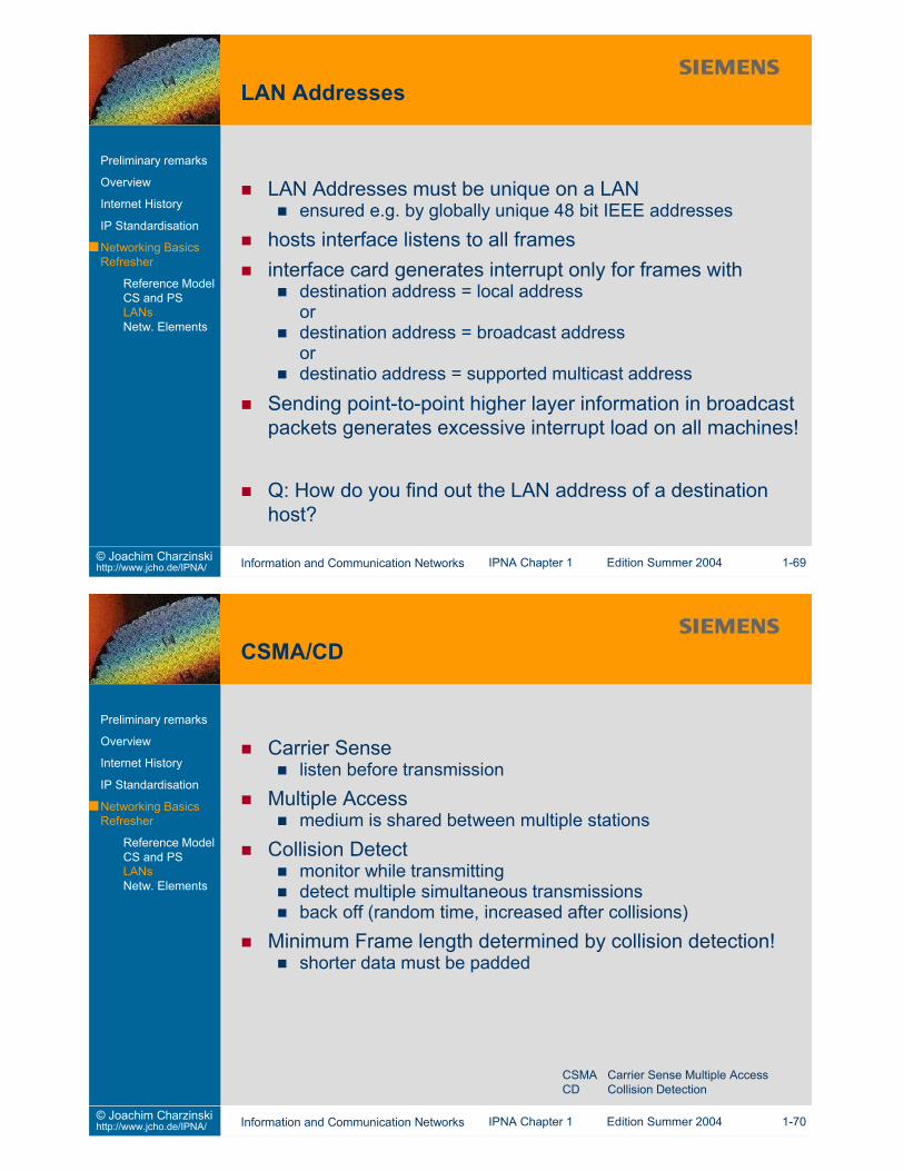
What is a LAN?Multiple systems attached to a shared medium“high” total bandwidth, shared by the stations“low” delay“low” error ratebroadcast/multicast capability
single message (frame) transmitted onceand received by multiple recipients
limited geography (max. some km)limited number of stations (max. few hundred)all stations are equivalent (no master/slave)privately operated, not governed by telecommunicationsregulations(i.e. “data communication” in contrast to “telecommunication”)
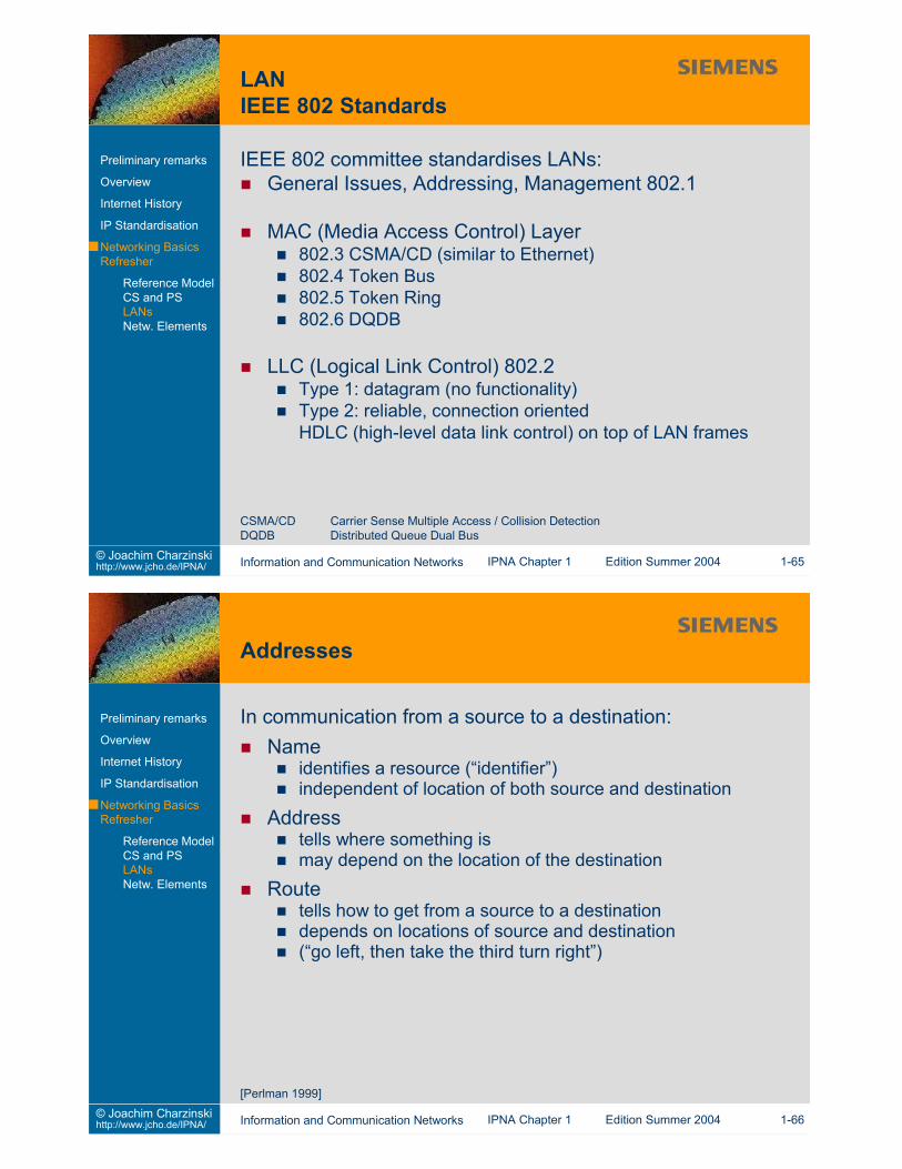
MAC (Media Access Control) Layer802.3 CSMA/CD (similar to Ethernet)802.4 Token Bus802.5 Token Ring802.6 DQDB
LLC (Logical Link Control) 802.2Type 1: datagram (no functionality)Type 2: reliable, connection orientedHDLC (high-level data link control) on top of LAN frames
CSMA/CD Carrier Sense Multiple Access / Collision DetectionDQDB Distributed Queue Dual Bus
16 bit addresses (option in the IEEE standards)enough for any LAN if configured during network start-upnot used
48 bit addresses for Ethernet / 802.3 LAN interfacesinitialised by hardware manufacturers in a globally unique wayfirst 3 octets: vendor code (organizationally unique identifier,OUI)last 3 octets: unique hardware IDe.g. “00-60-8c-f9-cf-30”
see http://standards.ieee.org/regauth/oui/oui.txtBit and byte orders depend on LAN standard
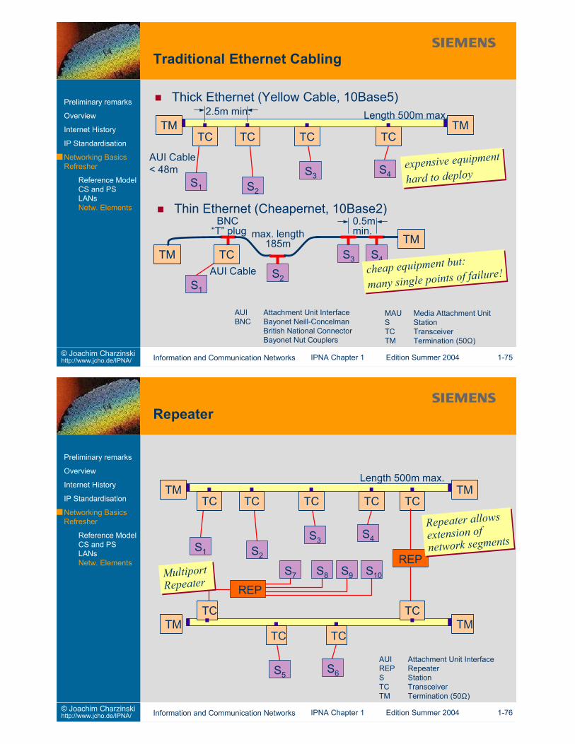
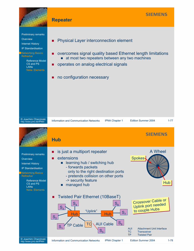
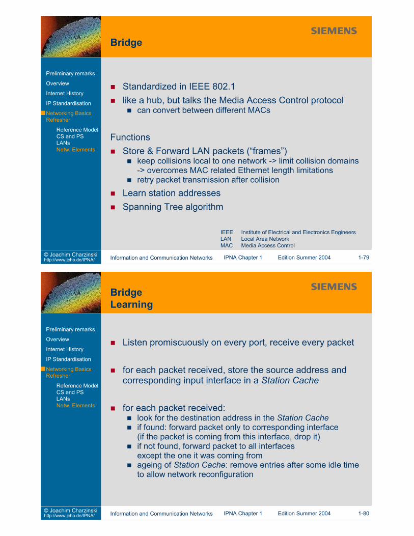
Standardized in IEEE 802.1like a hub, but talks the Media Access Control protocol
can convert between different MACs
FunctionsStore & Forward LAN packets (“frames”)
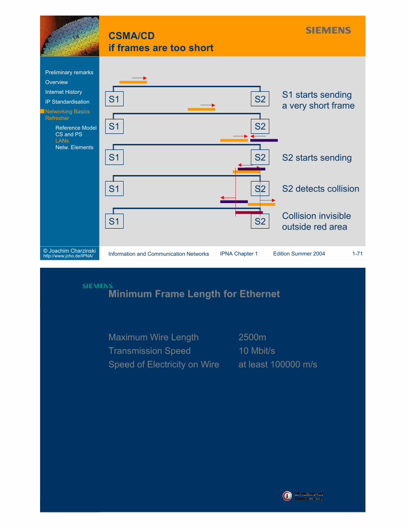
keep collisions local to one network -> limit collision domains-> overcomes MAC related Ethernet length limitationsretry packet transmission after collision
Learn station addressesSpanning Tree algorithm
IEEE Institute of Electrical and Electronics EngineersLAN Local Area NetworkMAC Media Access Control
Listen promiscuously on every port, receive every packet
for each packet received, store the source address andcorresponding input interface in a Station Cache
for each packet received:look for the destination address in the Station Cacheif found: forward packet only to corresponding interface(if the packet is coming from this interface, drop it)if not found, forward packet to all interfacesexcept the one it was coming fromageing of Station Cache: remove entries after some idle timeto allow network reconfiguration
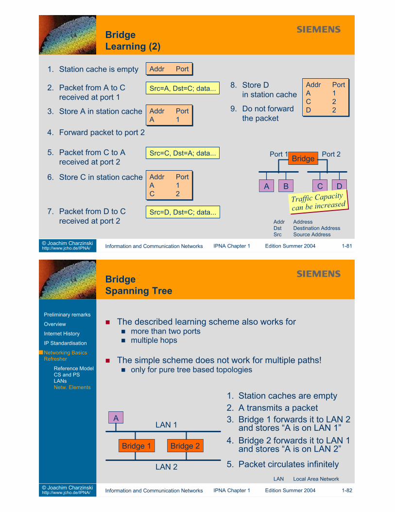
Bridges use a “spanning tree” algorithm to convert anytopology into a loop-free subsetprotocol uses configuration messages (“configuration bridgeprotocol data units”)
steps at each bridge during configuration BPDU exchange:1. Elect one single bridge to be the Root Bridge (lowest ID)2. Calculate distance of shortest path
from this bridge to the root bridge3. For each LAN, elect a Designated Bridge
(closest to the root bridge)4. Choose a port (“root port”) that gives the
best path from this bridge to the Root Bridge5. Root port plus the ports on which this bridge has been elected
Designated Bridge will be included in the spanning tree
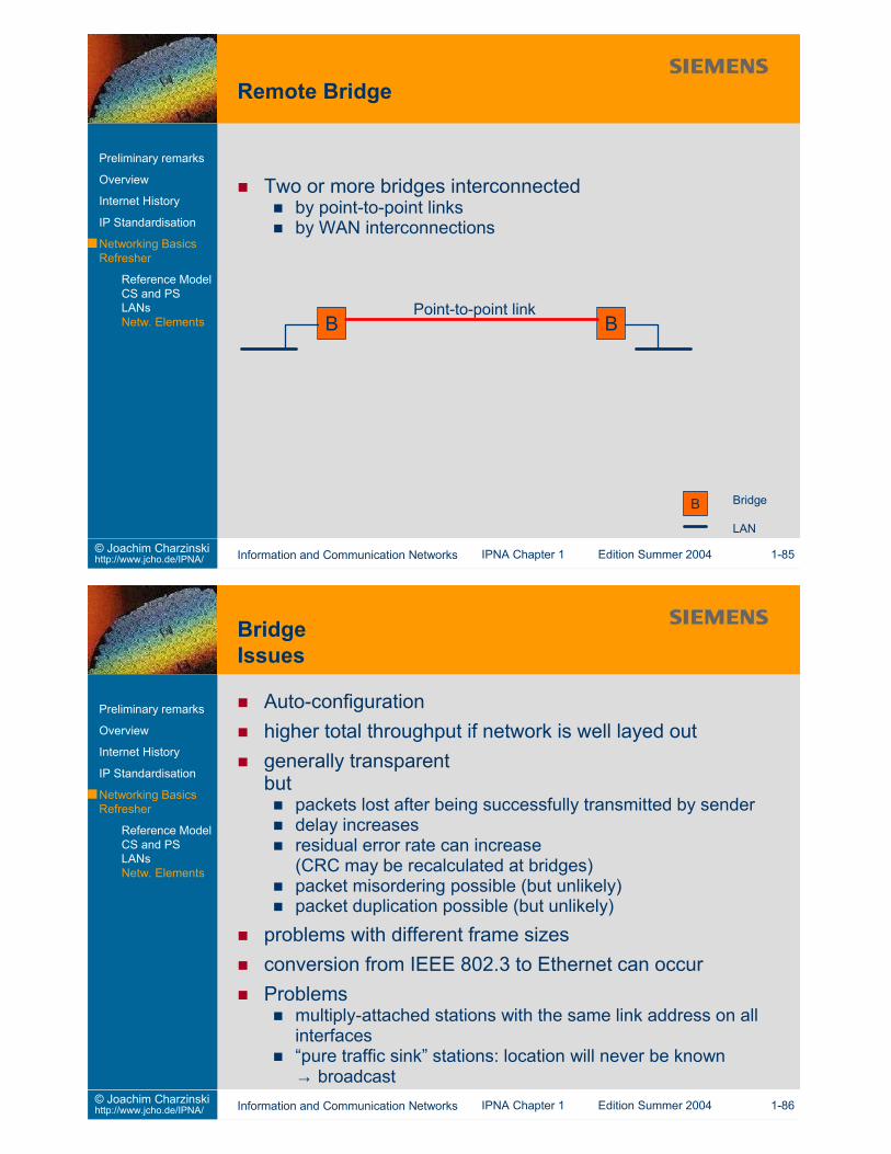
Auto-configurationhigher total throughput if network is well layed outgenerally transparentbut
packets lost after being successfully transmitted by senderdelay increasesresidual error rate can increase(CRC may be recalculated at bridges)packet misordering possible (but unlikely)packet duplication possible (but unlikely)
problems with different frame sizesconversion from IEEE 802.3 to Ethernet can occurProblems
multiply-attached stations with the same link address on allinterfaces“pure traffic sink” stations: location will never be known→ broadcast
A) Term for a Bridge with many portse.g. Ethernet Switch
B) Term for a telecommunications devicee.g. Voice Switch, ATM Switch
C) Term for a combination of bridging and routing functionsfrom Multiport Ethernet bridge with IGMP snoopingto configurable setting of routed / bridged ports
D) Term for any fast and modernnetwork interconnection device
e.g. “Layer 4+ Switch”
...ATM Asynchronous Transfer ModeIGMP Internet Group Management Protocol
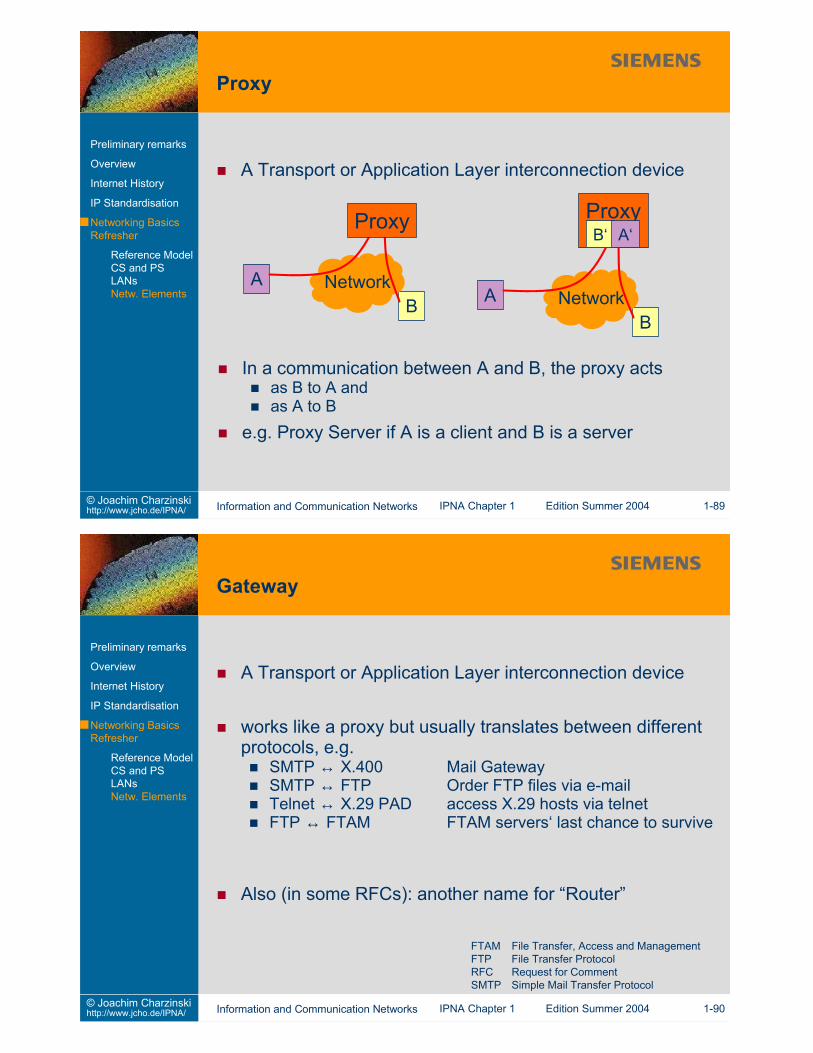
A Transport or Application Layer interconnection device
works like a proxy but usually translates between differentprotocols, e.g.
SMTP ↔ X.400 Mail GatewaySMTP ↔ FTP Order FTP files via e-mailTelnet ↔ X.29 PAD access X.29 hosts via telnetFTP ↔ FTAM FTAM servers‘ last chance to survive
Also (in some RFCs): another name for “Router”
FTAM File Transfer, Access and ManagementFTP File Transfer ProtocolRFC Request for CommentSMTP Simple Mail Transfer Protocol
This slide set is distributed to support students of the University of Stuttgart who attend the IPNA lectureduring summer term 2004. All other use requires written permission by Joachim Charzinski.
1. Introduction2. Network Layer (et al.)3. Transport Layer4. Applications and Application Layer Protocols5. Network Architectures6. Statistics and Performance7. Quality of Service8. Network Management9. Security
classification of classical functions / network rangesPhysical Layer: bit and byte transmission technology, physicalconnectionLogical Link Layer, Subnetwork Layer:~packet transmission on one physical networkNetwork Layer, Internetwork Layer: Communication overmultiple networksTransport Layer: end-to-end communicationHigher layers / Application Layer: application specific protocolsand services, e.g. HTTP for Web browser/server communication
Layers are relative to one networking paradigme.g. ISDN (L3) can be used as L1/2 for Internet accessIP (L3) can be tunneled over IP (L3)
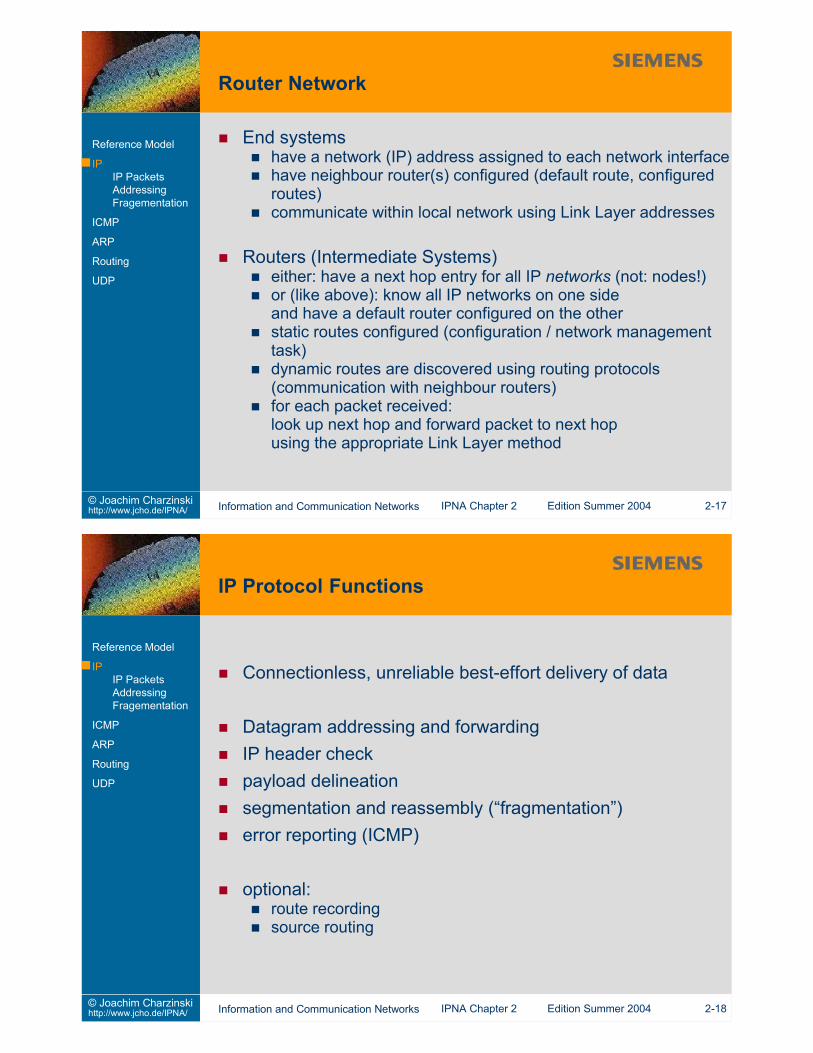
End systemshave a network (IP) address assigned to each network interfacehave neighbour router(s) configured (default route, configuredroutes)communicate within local network using Link Layer addresses
Routers (Intermediate Systems)either: have a next hop entry for all IP networks (not: nodes!)or (like above): know all IP networks on one sideand have a default router configured on the otherstatic routes configured (configuration / network managementtask)dynamic routes are discovered using routing protocols(communication with neighbour routers)for each packet received:look up next hop and forward packet to next hopusing the appropriate Link Layer method
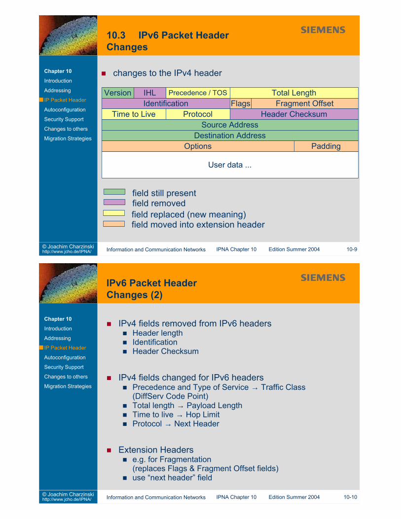
Total Length (16 bits)length of the datagram (in octets), including IP header and dataat most 65535 octetsall hosts must be able to accept a datagram of 576 octets(512+64)only send datagrams longer than 576 octets if the receiver canhandle them
Identification (16 bits)identification of transmitted datagramunique for transmitter (for the next 65535 packets)used by receiver to reassemble fragmented datagrams
Control Flags (3 bits)Bit 0: must be zero (“MBZ”)Bit 1: DF 1 = don’t fragment 0 = may fragmentBit 2: MF 1 = more fragments 0 = last fragment
Fragment Offset (13 bits)counts 8 octet (64 bits) wordsindicates where the current fragment belongs in the datagram
Time to Live (TTL) (8 bits)indicates the maximum residual time the datagram is allowed toremain in the networkRFC791: “measured in seconds“, but:each router must decrement the TTL value by 1
-> effectively implemented as “residual hop count”necessary to avoid infinitely circling packets in the case of arouting loop(special problem of connectionless packet switching!)
Protocol (8 bits)indicates the next layer protocol (usually transport layer)
EGP Exterior Gateway ProtocolICMP Internet Control Message ProtocolIGMP Internet Group Management ProtocolIGP Interior Gateway ProtocolIGRP Cisco Interior Gateway Routing ProtocolIP Internet ProtocolNHRP Next Hop Resolution ProtocolRSVP Resource Reservation ProtocolTCP Transmission Control ProtocolUDP User Datagram Protocol
Header checksum (16 bits)checksum computed on the IP headerre-computed at every node that changes the header (e.g. theTTL field!)16 bit one’s complement of one’s complement sum of all 16 bitfields in the IP header (taking the checksum field to be zero forcomputation)
Source Address (32 bits)see section 2.2.2
Destination Address (32 bits)see section 2.2.2
Options (variable length)zero or more optionsCase 1: single octet optionCase 2: option type (1 oct.) +option length (1 oct.) +option-data
Paddingincreases the IP header length to the next integer multiple of4 octets
Option Lengthnumber of octets in (option-type + option-length + option-data)
Option Type
Copy Flag (CF): 1 = copy / 0 = do not copy(controls treatment of options under fragmentation)Option Class (OC):0 = control2 = debugging & measurement1,3 = reserved for future use
0 0 – End of option list. Used for padding.No length octet.
0 1 – No operation. No length octet.0 2 11 Security and handling restrictions (US DoD)0 3 var. Loose source route. Request routing along
the specified routers.0 7 var. Record Route. Collect the addresses
of routers along the path.0 8 4 Strem identifier (SATNET, obsolete)0 9 var. Strict source route.0 11 4 MTU probe. Used for path MTU discovery.0 12 4 MTU probe reply.
Used for path MTU discovery.0 20 4 Router alert. Request router to process
end-to-end packet contents. (RFC2113)2 4 var. Record timestamps along a route.2 18 var. Traceroute. To find routers along a path.
Length Description
DoD Department of DefenseMTU Maximum Transmission Unit
Machines store data in different formats, even for integersLittle Endian:Lowest memory address contains lowest-order byte of aninteger.Big Endian:Lowest memory address contains highest-order byte of aninteger.plus: byte-swapping within 16 bit words
Standardized Network Byte OrderOnly a machine independent interpretation allows interworking!
IP, TCP and UDP: Transmit most significant byte first
extra issue for application protocols:transmission data formats must be defined individually
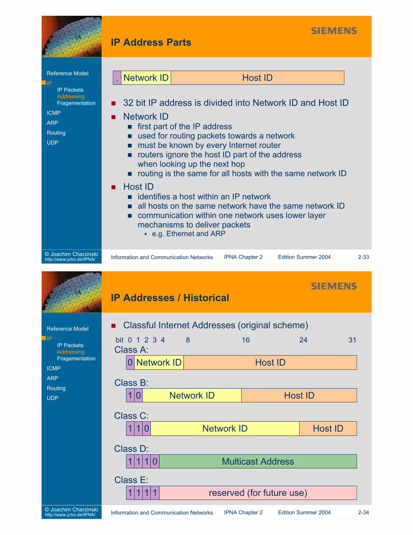
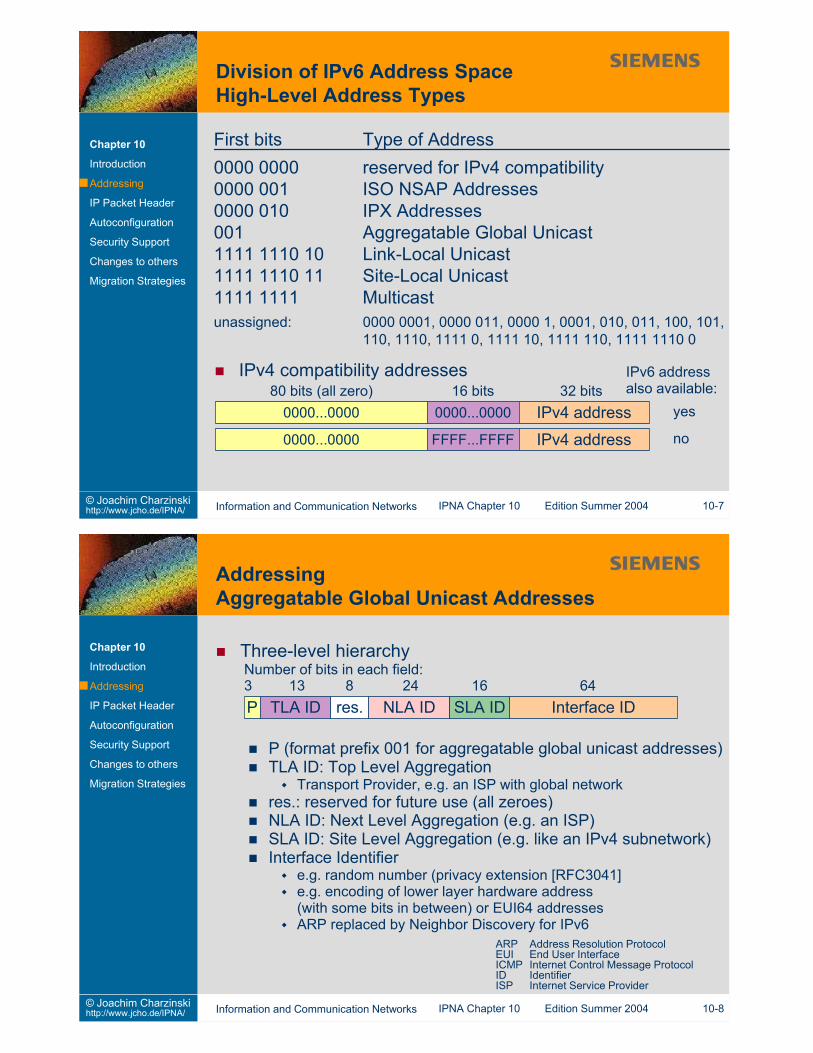
32 bit IP address is divided into Network ID and Host IDNetwork ID
first part of the IP addressused for routing packets towards a networkmust be known by every Internet routerrouters ignore the host ID part of the addresswhen looking up the next hoprouting is the same for all hosts with the same network ID
Host IDidentifies a host within an IP networkall hosts on the same network have the same network IDcommunication within one network uses lower layermechanisms to deliver packets
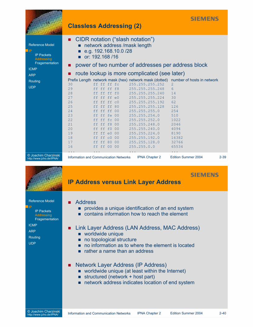
basically like subnetting, butalso used in WANalso to reduce network mask
reasons:only 16384 class B networks-> “ROADS” (running out of address space) problemonly few of the ~2 million class C networks are really assigned
combine e.g. multiple class C networks into a larger networkonly one common routing entry in wide area network routersadditional prefix lengthto be stored and used for routing
“Classless Inter-Domain Routing” (CIDR)[RFC1518, RFC1519]specify prefix length along with network address(number of “1” bits in network mask)knowledge of prefix for each network address required by allWAN routerswork-around (historical, expensive!):insert many routes to classful network addresses
Addressprovides a unique identification of an end systemcontains information how to reach the element
Link Layer Address (LAN Address, MAC Address)worldwide uniqueno topological structureno information as to where the element is locatedrather a name than an address
Network Layer Address (IP Address)worldwide unique (at least within the Internet)structured (network + host part)network address indicates location of end system
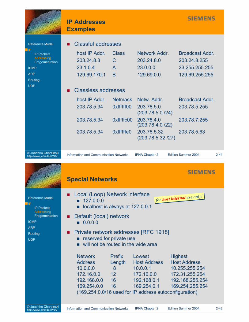
Classful addresseshost IP Addr. Class Network Addr. Broadcast Addr.203.24.8.3 C 203.24.8.0 203.24.8.25523.1.0.4 A 23.0.0.0 23.255.255.255129.69.170.1 B 129.69.0.0 129.69.255.255
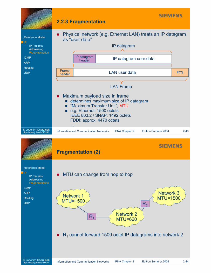
Physical network (e.g. Ethernet LAN) treats an IP datagramas “user data”Reference Model
IPIP PacketsAddressingFragementation
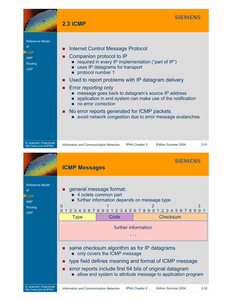
ICMP
ARP
Routing
UDP
IP datagram user dataIP datagramheader
Frameheader FCS
IP datagram
LAN Frame
LAN user data
Maximum payload size in framedetermines maximum size of IP datagram“Maximum Transfer Unit”, MTUe.g. Ethernet: 1500 octetsIEEE 803.2 / SNAP: 1492 octetsFDDI: approx. 4470 octets...
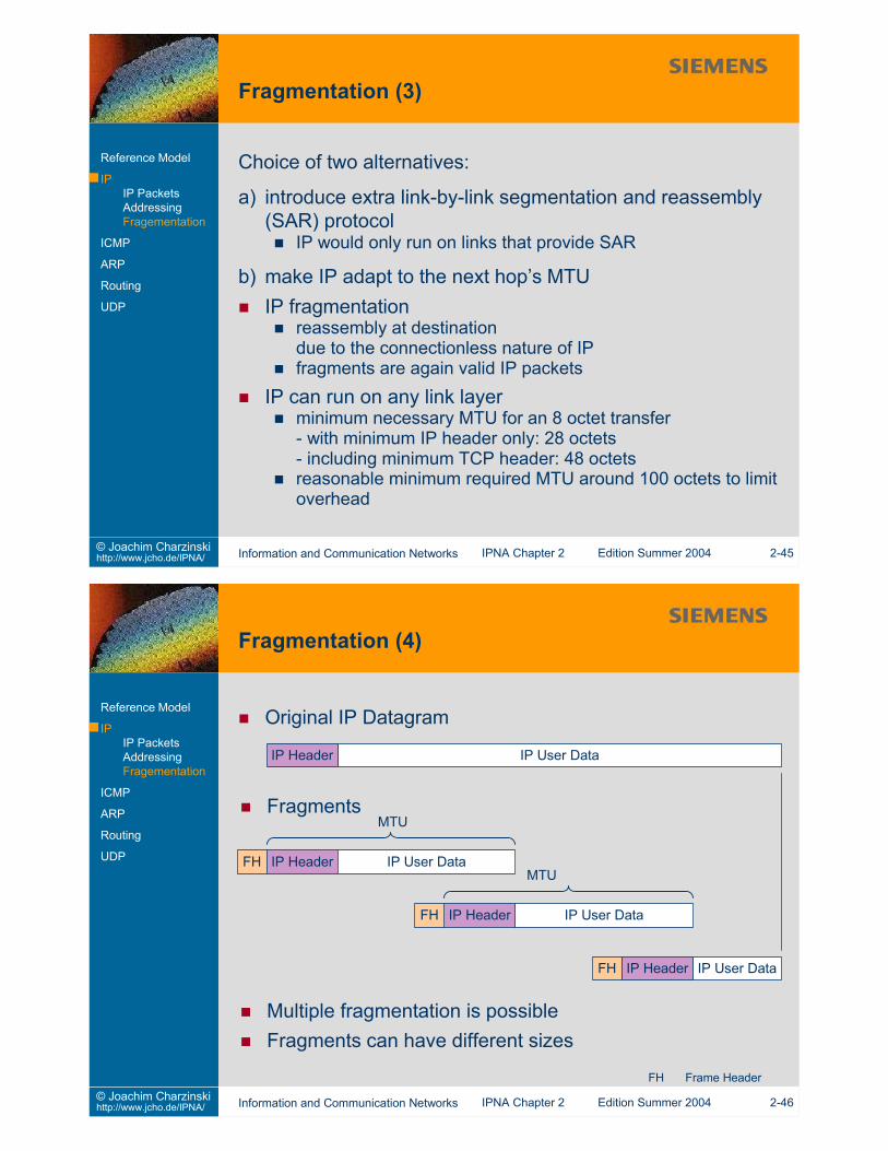
a) introduce extra link-by-link segmentation and reassembly(SAR) protocol
IP would only run on links that provide SAR
b) make IP adapt to the next hop’s MTUIP fragmentation
reassembly at destinationdue to the connectionless nature of IPfragments are again valid IP packets
IP can run on any link layerminimum necessary MTU for an 8 octet transfer- with minimum IP header only: 28 octets- including minimum TCP header: 48 octetsreasonable minimum required MTU around 100 octets to limitoverhead
Datagram ID used to collect fragments for reassembly
Total Length field in IP header gives length of fragment,not of the original datagram
original datagram length only known after reception of the lastfragment(MF flag = 0)receiver needs to reserve large reassembly buffer
Don’t Fragment flag in IP headerfragmentation not allowedrouter will send ICMP message back to sender (see sec. 2.3)can be used to test maximum possible datagram sizeused to avoid having the receiver reassemble a datagram
10 Router Solicitation11 Time exceeded for a datagram12 Parameter problem on a datagram13 Timestamp Request14 Timestamp Reply15 Information Request (obsolete)16 Information Reply (obsolete)17 Address Mask Request18 Address Mask Reply
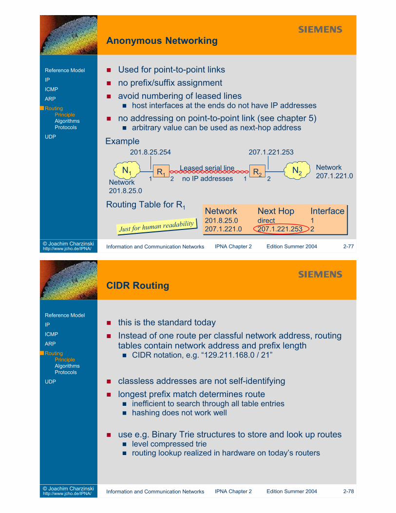
Routers are assumed to know a correct route to thedestinationhosts have minimal routing information
can be started up knowing only one routermay learn additional information from routers
Type (5) Code (0–3) Checksum
Router Internet Address
0 8 16 31
IP header + first 64 bits of datagram. . .
0 Redirect datagrams for the Net (now obsolete)1 Redirect datagrams for the Host2 Redirect datagrams for the Type of Service and Net3 Redirect datagrams for the Type of Service and Host
Ask available routers to send an advertisement immediatelyused by freshly booted hostssend to broadcast address (255.255.255.255)or to the “all routers” multicast address (224.0.0.2)
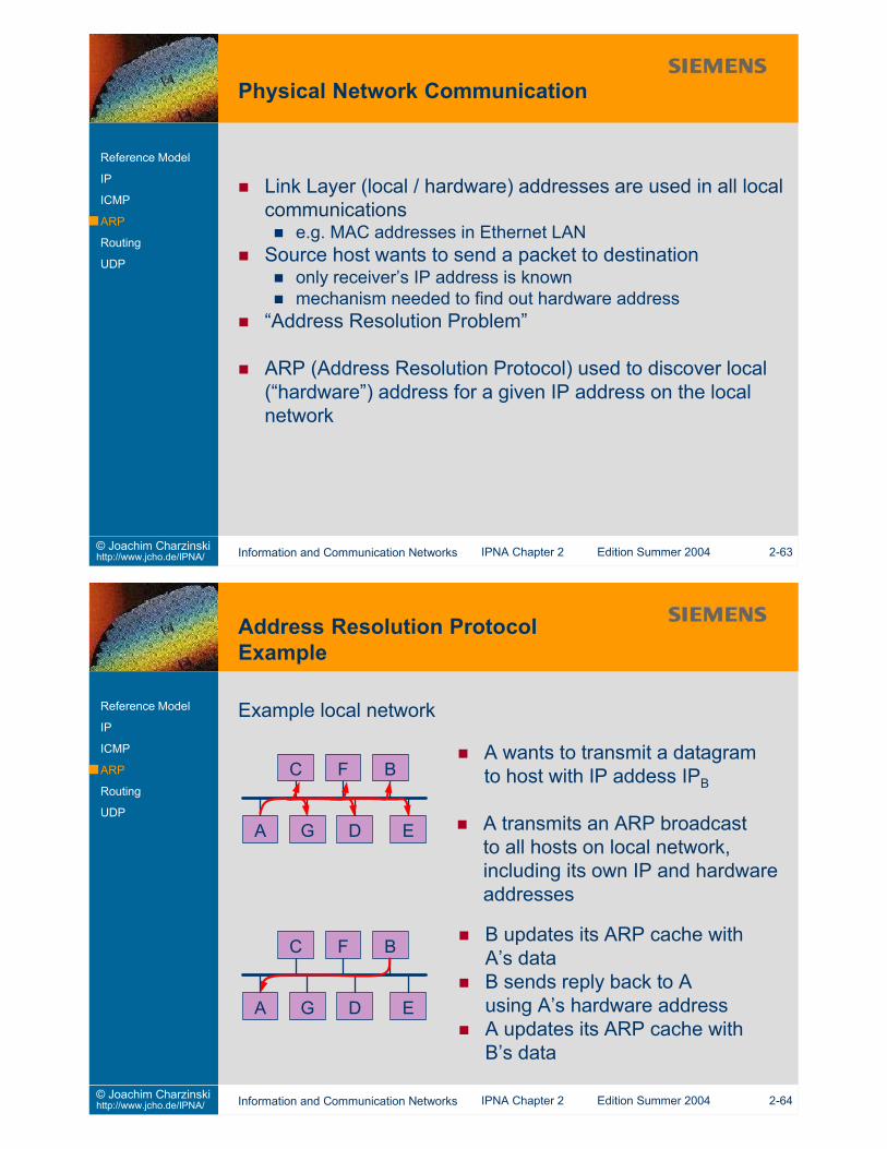
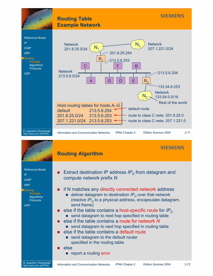
Extract destination IP address IPD from datagram andcompute network prefix N
if N matches any directly connected network addressdeliver datagram to destination IPD over that network(resolve IPD to a physical address, encapsulate datagram,send frame)
else if the table contains a host-specific route for IPDsend datagram to next hop specified in routing table
else if the table contains a route for network Nsend datagram to next hop specified in routing table
else if the table contains a default routesend datagram to the default routerspecified in the routing table
get next hop from routing tableget hardware address for next hop (ARP / ARP cache)reduce Time To Live (usually by 1)recompute header checksumsend datagram on local networkto the next hop’s hardware address
address fields in IP header are not modified!(exception: source routing option fields)
check if 32bit AND of destination address and network mask inrouting table entry is equal to network address in routing tableentrynext hop still needs to be accessible on the local network
Beware of ambiguities!Use consistent subnet masks across all networks within thesame subnetted IP network
otherwise subnet broadcasting is ambiguoususe contiguous bits to form subnet maskshosts can obtain local subnet maks from router via ICMP
Subnet Mask Network Address Next HopSubnet Mask Network Address Next Hop
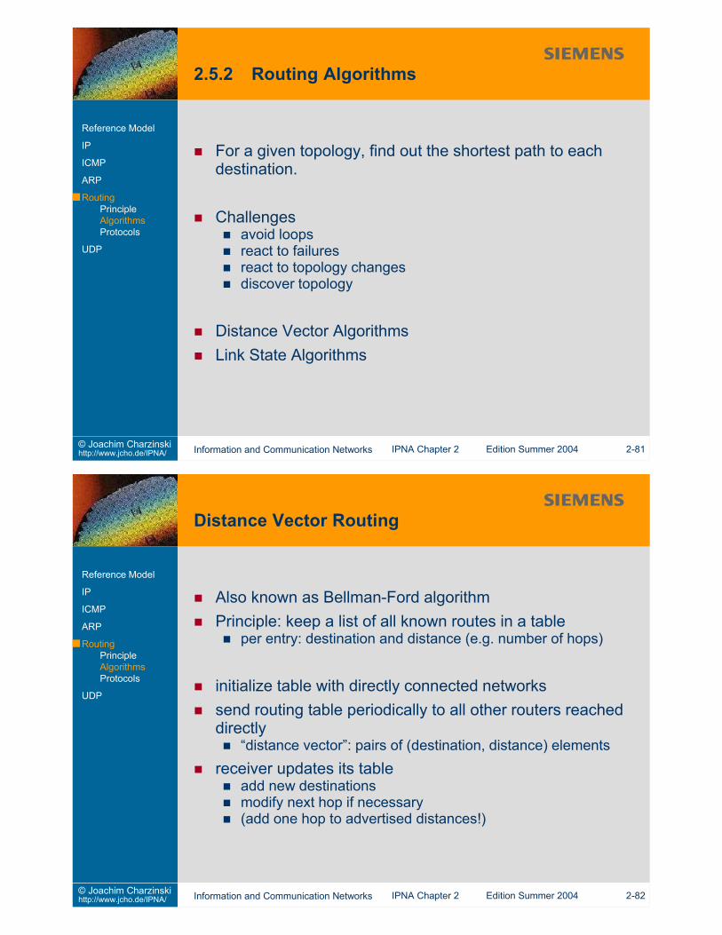
Each router has complete topology informationgraphnodes = routersedges = links (only if two routers can communicate directly)interface cost and link cost metrics
Router actionsactively test status of all direct links(with tolerance: k out of n HELLO packets must be received)distribute link status information to all other routers (broadcast)compute new shortest paths using Dijkstra’s Shortest Pathalgorithm on the graph
Routing protocols used todiscover routespropagate route informationvalidate routescheck route consistency
Autonomous System (AS)group of networks and routers controlled by a singleadministrative authorityhidden networks advertised to other AScentral assignment of AS numbers
Communication between different Autonomous Systemsexterior gateway protocols (EGP)propagation of reachability informationrouting metrics are not communicated or interpretedinternal structures are hidden
Communication within Autonomous Systemsinterior gateway protocols (IGP)propagation of reachability informationpropagation of routing metrics (distance, cost, etc)optimisation possible using internal structure information
an exterior gateway protocolcoordinates information released from different BGP routerswithin the same ASpropagates reachability informationsupplies next-hop informationmixture between distance-vector and link state protocolpolicy can hide selected parts of an ASruns over TCP (reliable transport!)communicates changes as incremental updatessupports CIDRsupports route aggregationsupports authentication (sender of messages can beverified)implemented in Unix gated
AS Autonomous SystemBGP Border Gateway ProtocolCIDR Classless Inter Domain RoutingTCP Transmission Control Protocol
Message TypesOpen initialize communicationUpdate advertise or withdraw routesNotification response to an incorrect messageKeepalive actively test peer connectivity
Marker in message headerallows message delineation from octet stream delivered by TCP
additional configuration needed in case of multipleinterconnections
routing arbiter system: one route server running BGP
metric transformation allows interworking with IGPsroutes between hosts in the same AS should not leave the AS
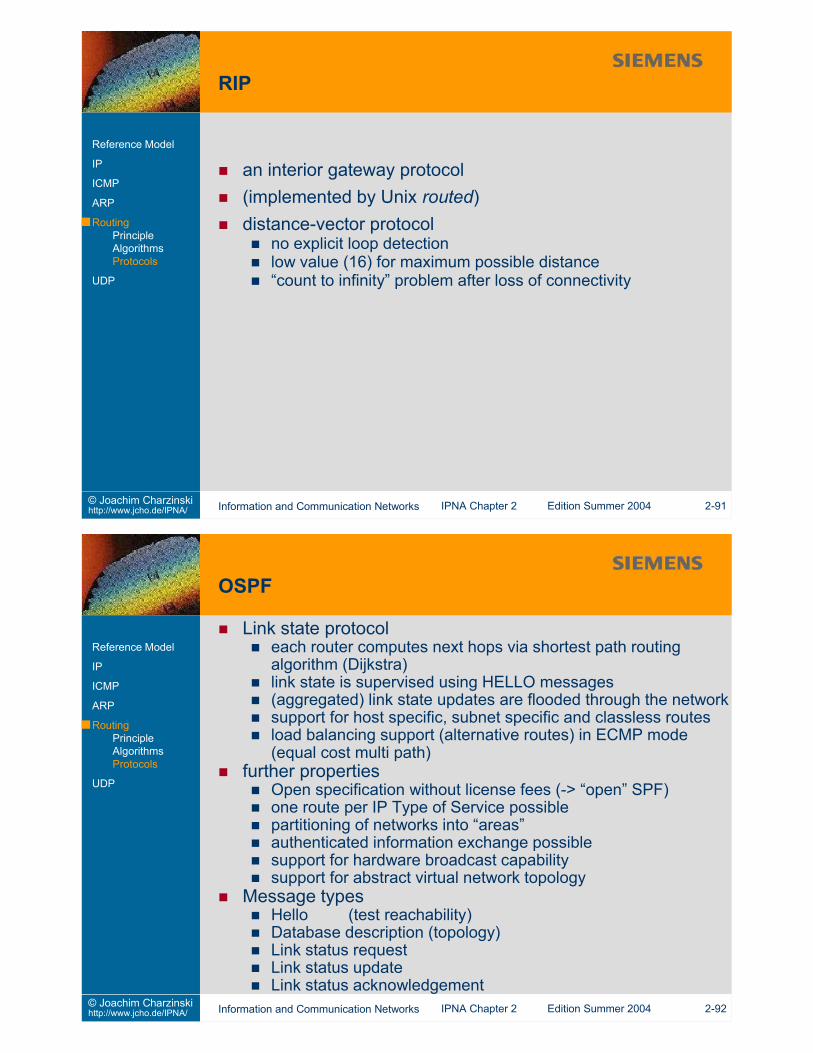
Link state protocoleach router computes next hops via shortest path routingalgorithm (Dijkstra)link state is supervised using HELLO messages(aggregated) link state updates are flooded through the networksupport for host specific, subnet specific and classless routesload balancing support (alternative routes) in ECMP mode(equal cost multi path)
further propertiesOpen specification without license fees (-> “open” SPF)one route per IP Type of Service possiblepartitioning of networks into “areas”authenticated information exchange possiblesupport for hardware broadcast capabilitysupport for abstract virtual network topology
Message typesHello (test reachability)Database description (topology)Link status requestLink status updateLink status acknowledgement
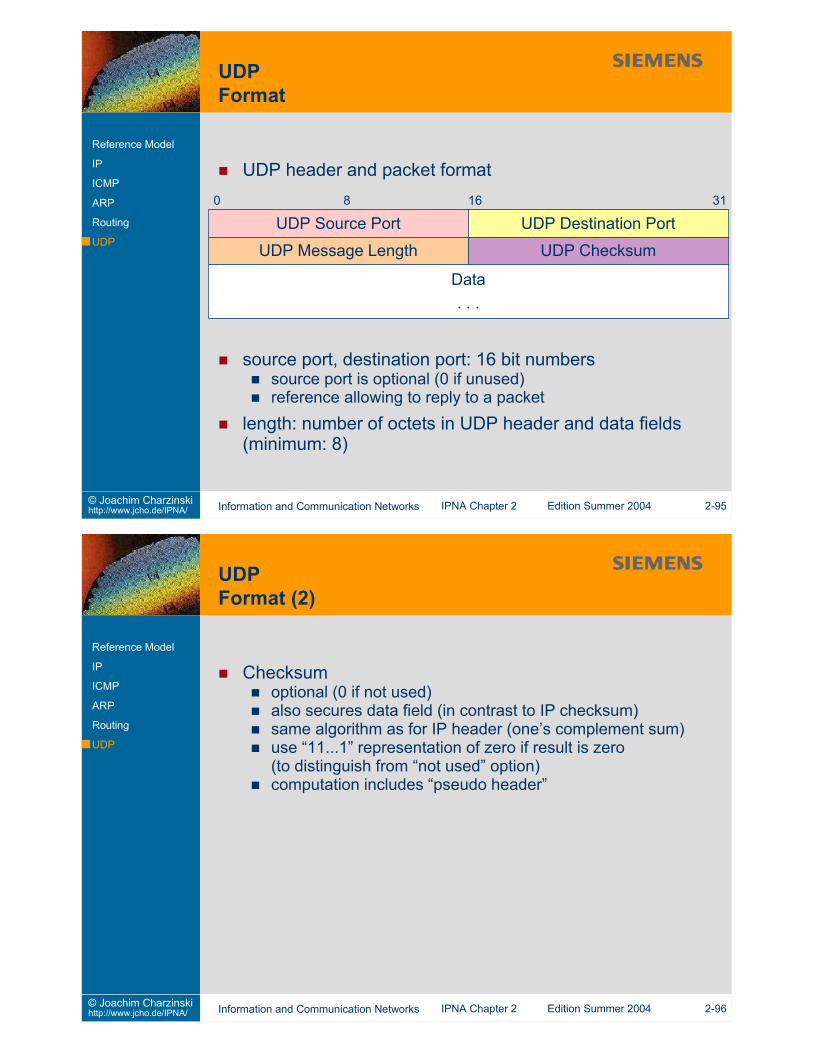
Checksumoptional (0 if not used)also secures data field (in contrast to IP checksum)same algorithm as for IP header (one’s complement sum)use “11...1” representation of zero if result is zero(to distinguish from “not used” option)computation includes “pseudo header”
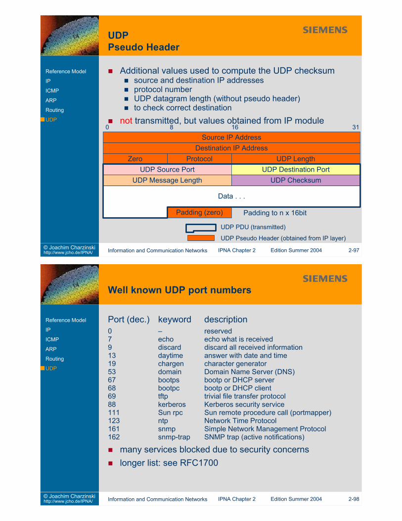
Additional values used to compute the UDP checksumsource and destination IP addressesprotocol numberUDP datagram length (without pseudo header)to check correct destination
not transmitted, but values obtained from IP module
UDP Source Port UDP Destination PortUDP ChecksumUDP Message Length
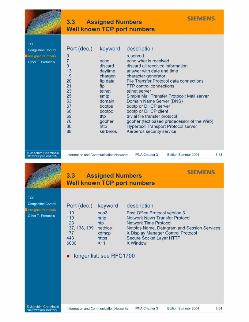
Port (dec.) keyword description0 – reserved7 echo echo what is received9 discard discard all received information13 daytime answer with date and time19 chargen character generator53 domain Domain Name Server (DNS)67 bootps bootp or DHCP server68 bootpc bootp or DHCP client69 tftp trivial file transfer protocol88 kerberos Kerberos security service111 Sun rpc Sun remote procedure call (portmapper)123 ntp Network Time Protocol161 snmp Simple Network Management Protocol162 snmp-trap SNMP trap (active notifications)
many services blocked due to security concernslonger list: see RFC1700
2.1 What routes are configured in your end system?2.2 How many networks does University of Stuttgart use? How many
Class B networks?2.3 How many internet domains (third-level)?2.4 Why can reassembly only be done at the final destination?2.5 Examine the routing tables of hosts you have access to
(Hint: Use the “route“ or “netstat” tools)2.6 How does the “traceroute” program work?2.7 Modify the routing algorithm (2-71) to include source routing2.8 Which ICMP messages does a router generate?
2.9 Devise a simple protocol to recover from packet loss.2.10 What would you describe as fairness?2.11 Test the throughput on your local network with n parallel TCP
connections (n=1,2,3,4)2.12 Test the throughput on the Internet with n parallel TCP
This slide set is distributed to support students of the University of Stuttgart who attend the IPNA lectureduring summer term 2004. All other use requires written permission by Joachim Charzinski.
1. Introduction2. Network Layer (et al.)3. Transport Layer4. Applications and Application Layer Protocols5. Network Architectures6. Statistics and Performance7. Quality of Service8. Network Management9. Security
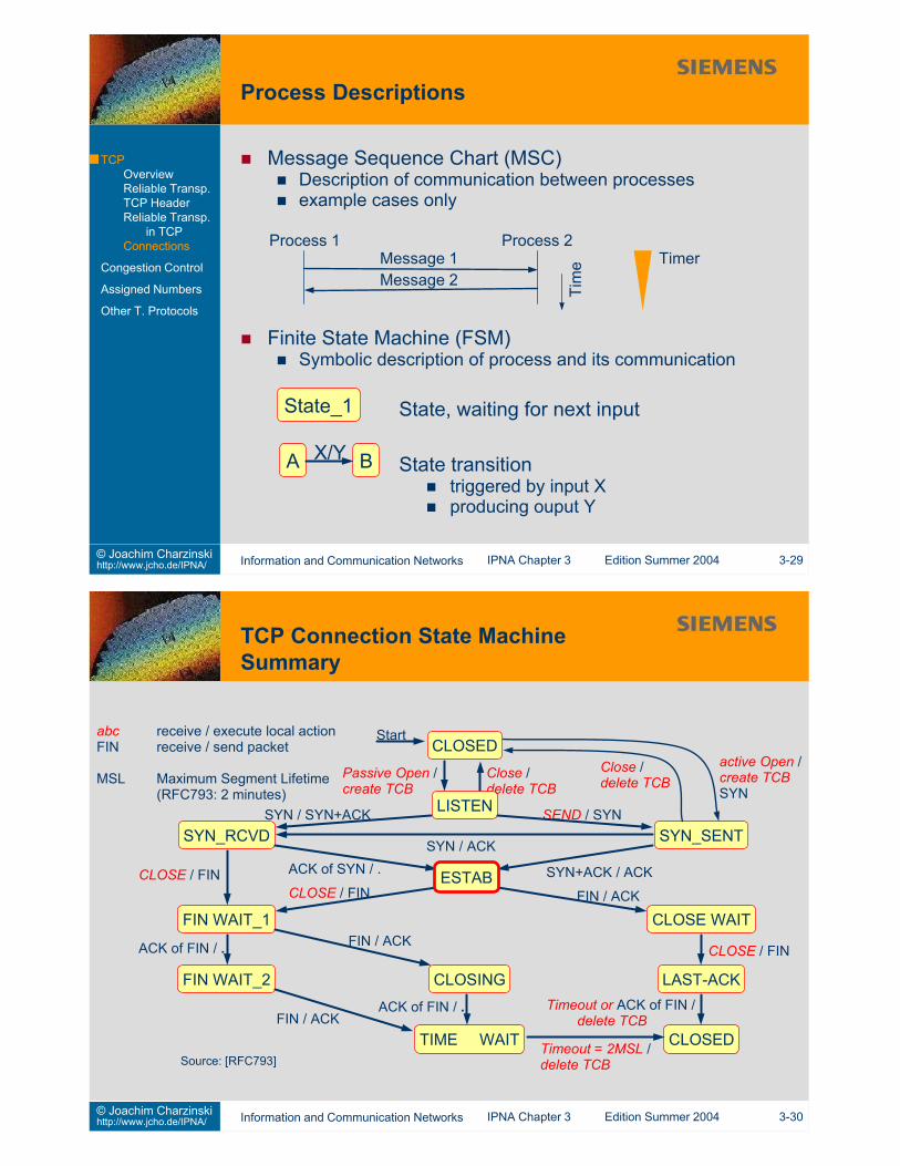
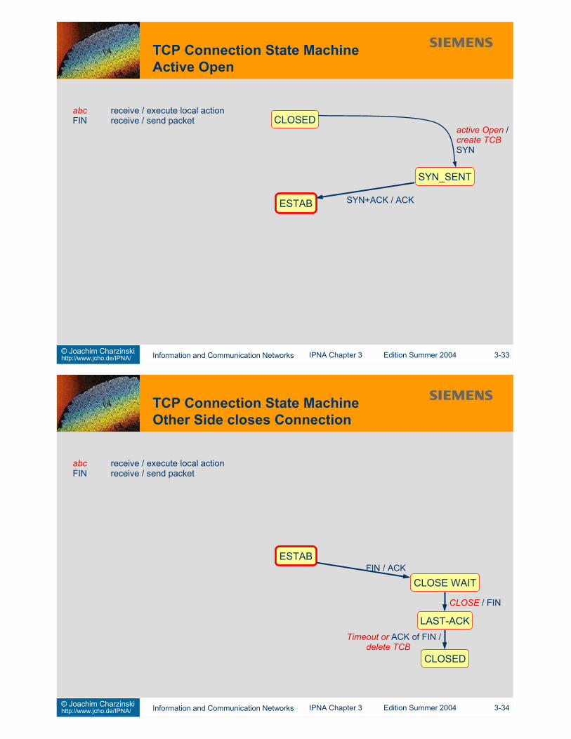
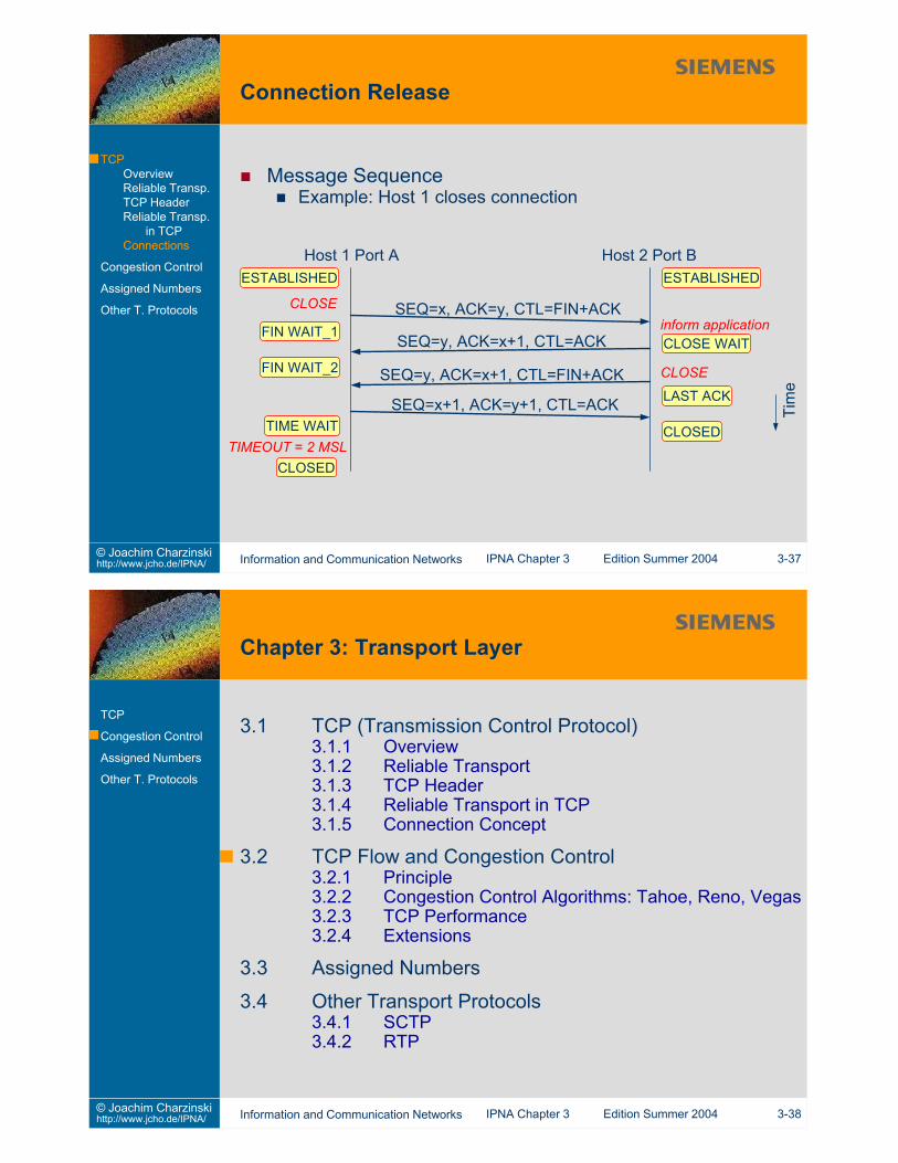
specified in RFC793 (Sep. 1981)clarified in RFC 1122 (Oct. 1989)
Some additions:Extensions for long delay [RFC 1072]Big Windows [RFC1106, RFC1110]Selective Acknowledgement [RFC 2018]Increasing TCP’s Initial Window [RFC 2414]NewReno Fast Recovery [RFC 2582]
Stream oriented transport protocoluser data taken as octet (byte) streamdelivered in the same octet sequence
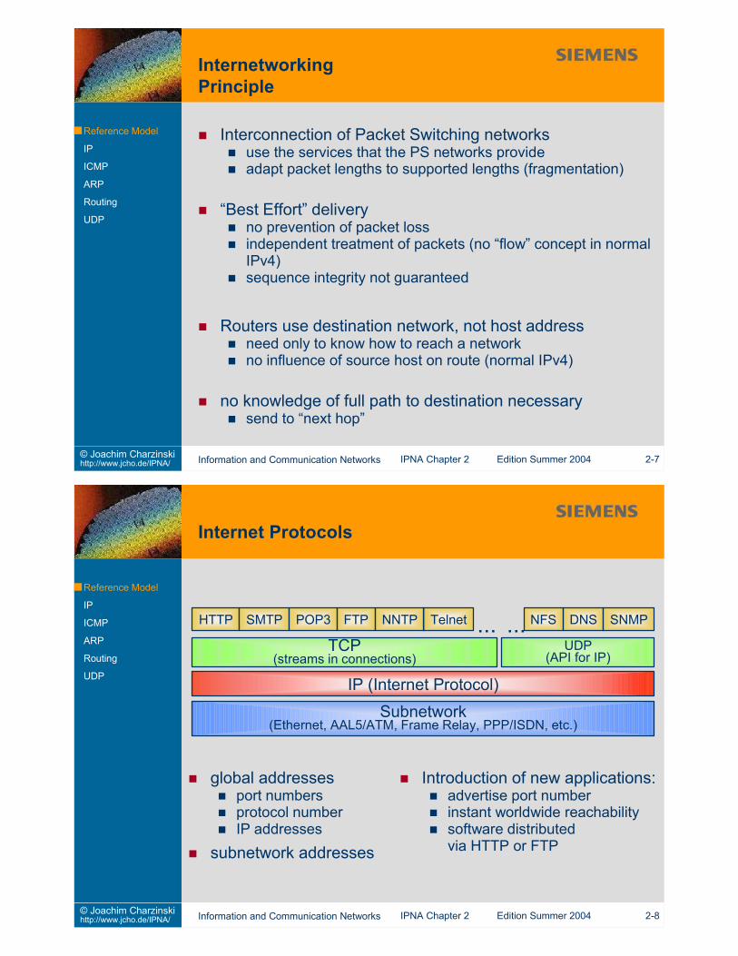
Virtual Circuit Connectionbuilds connection oriented service above connectionless layer(IP)
Buffered TransferTCP can collect user data from multiple user calls into onepacketincreased efficiency (less TCP/IP overhead per user data octet)“push”: deliver the data now (not necessarily as a singlepacket!)
Unstructured Streamapplication programs must define and parse stream formats
Full Duplex Connectionno need for opening a separate reverse connectionpiggy-backing of protocol control information
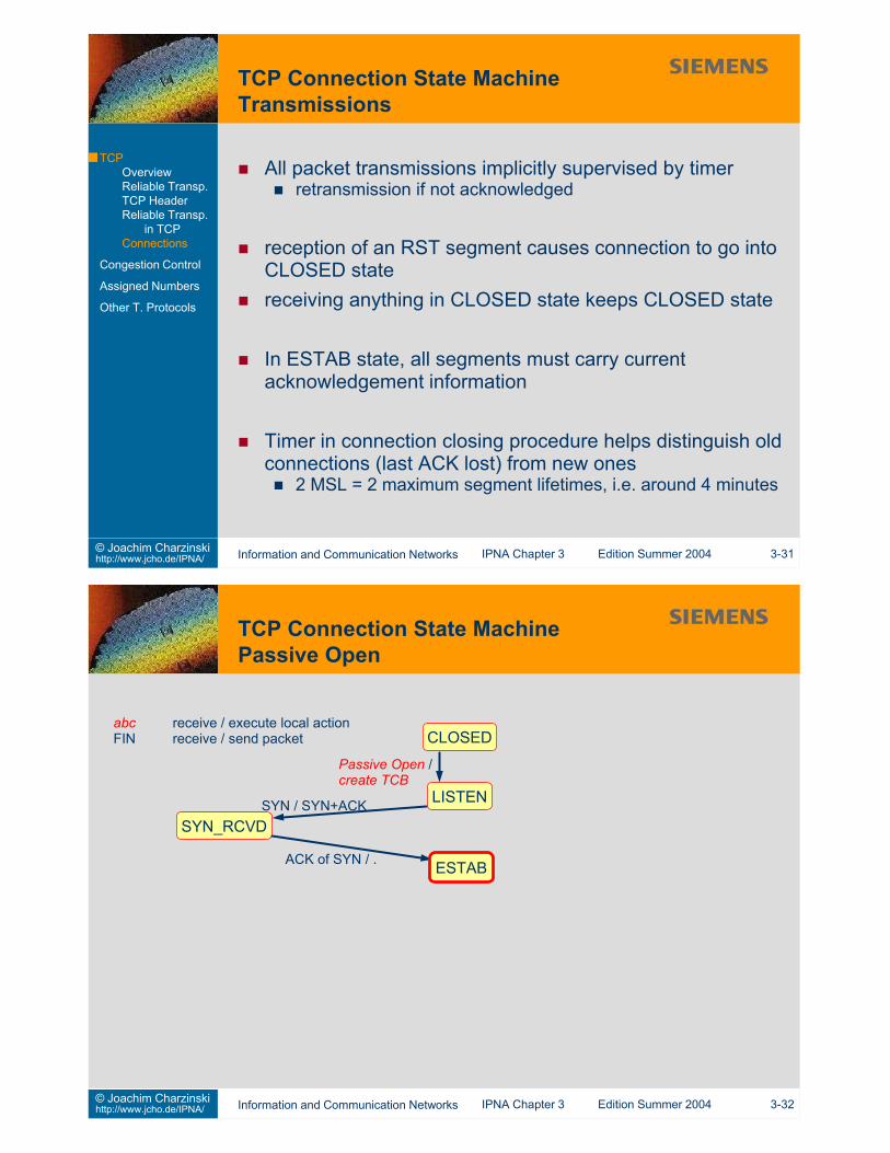
Openactive: open a connection to a communication partnerpassive: be ready to accept connections from a communicationpartner
Closetransmit remaining data, then close the connection
Sendsubmit data to transmitunstructured octet stream“push” if no more data are to come(e.g. when waiting for partner’s application layer protocol toanswer)
Larger transmission windowtransmit more packets untilacknowledgement is needed“sliding window”line speed can be reachedlonger sequence numbersneeded to avoid ambiguity
more packets to repeat after loss
Tim
e
Data Packet #1Data Packet #2Data Packet #3Data Packet #4
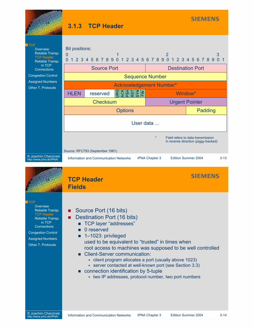
TCP layer “addresses”0 reserved1–1023: privilegedused to be equivalent to “trusted” in times whenroot access to machines was supposed to be well controlledClient-Server communication:
client program allocates a port (usually above 1023)server contacted at well-known port (see Section 3.3)
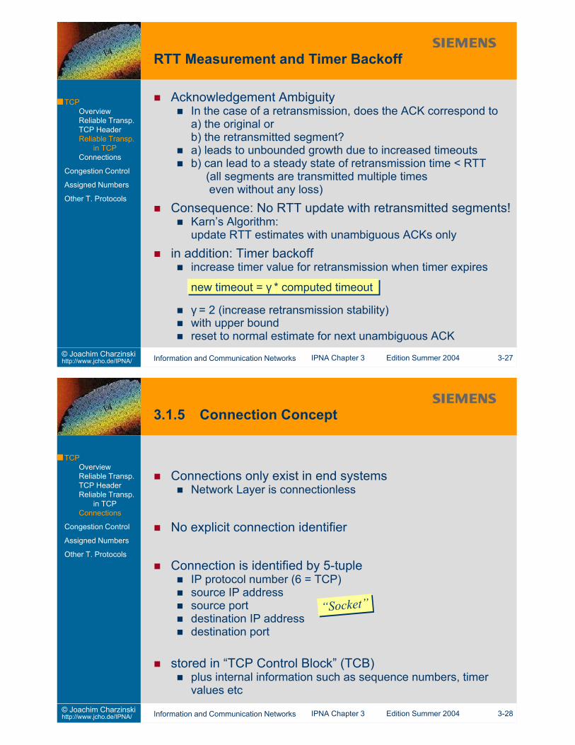
connection identification by 5-tupletwo IP addresses, protocol number, two port numbers
HLEN (4 bits)length of the TCP header (without IP) in 32bit wordsindicates position of first data octet in 32bit wordsRFC793: “data offset”TCP header length is always an integer of 32 bit
Reserved (6 bits)reserved for future usemust be zero
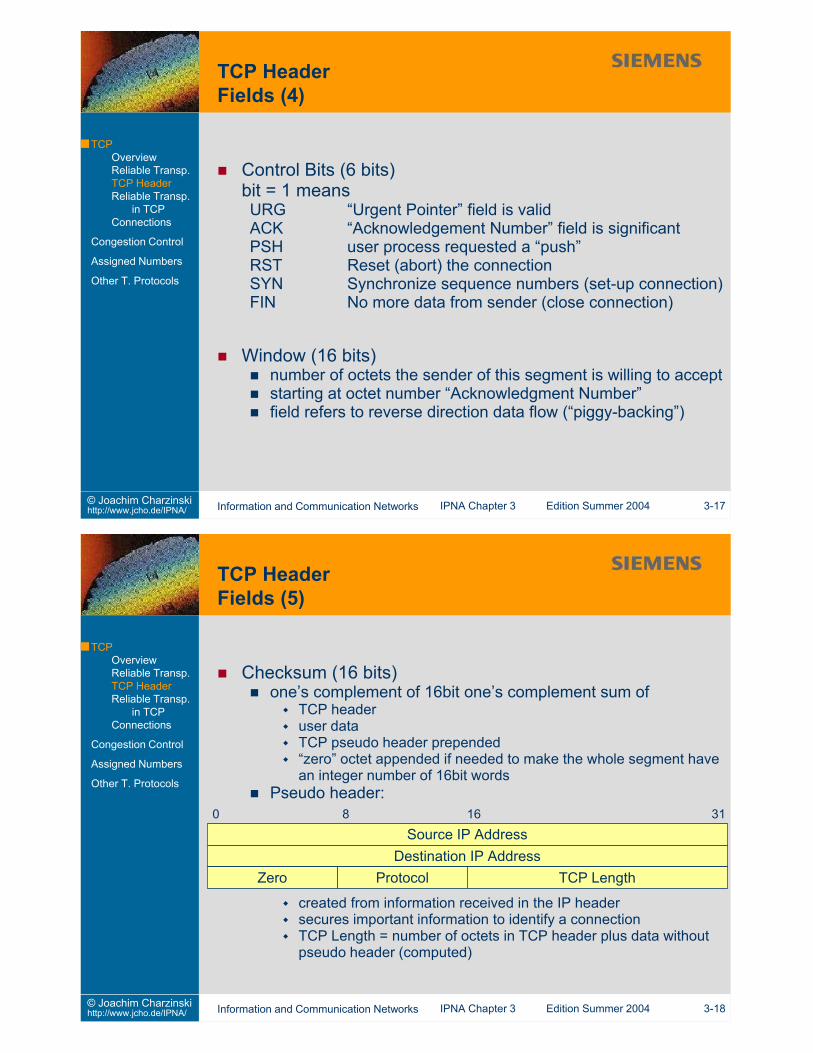
Control Bits (6 bits)bit = 1 meansURG “Urgent Pointer” field is validACK “Acknowledgement Number” field is significantPSH user process requested a “push”RST Reset (abort) the connectionSYN Synchronize sequence numbers (set-up connection)FIN No more data from sender (close connection)
Window (16 bits)number of octets the sender of this segment is willing to acceptstarting at octet number “Acknowledgment Number”field refers to reverse direction data flow (“piggy-backing”)
Checksum (16 bits)one’s complement of 16bit one’s complement sum of
TCP headeruser dataTCP pseudo header prepended“zero” octet appended if needed to make the whole segment havean integer number of 16bit words
Pseudo header:
created from information received in the IP headersecures important information to identify a connectionTCP Length = number of octets in TCP header plus data withoutpseudo header (computed)
Urgent Pointer (16 bits)only meaningful if the URG control bit is setused to indicate urgent data in the data fieldpositive offset from the sequence number of the segmentpoints to the sequence number of the first octet after the urgentdata(= number of “urgent” octets in the data field)used to send “out of band” data to applications ignoring normalinpute.g. to send a software interrupt to a program in a Telnetsession
Options (variable length)zero or more TCP optionsCase 1: single octet optionCase 2: option type (1 oct.), option length (1 oct.), option data
Padding (variable length)makes the TCP header length an integer multiple of 32 bits
Maximum given by “Maximum Segment Size” (MSS)per directiondefault: 536 octetsi.e. 576 octets IP datagram including standard IP and TCPheaders
segment size too smalllarge overhead due to sending one IP and TCP header persegment
segment size too largerisk of fragmentationIf one fragment of a segment is lost, the whole segment mustbe retransmitted (no reliable transport on the IP Layer).
Path MTU discovery [RFC 1191]send large segment with IP “don’t fragment” bit setreduce packet size and retryuntil no ICMP “fragmentation needed” message comes back
Send Segmentsegmentize send buffersend segment with piggybacked current acknowledgementput segment into retransmission buffer and set retransmissiontimer
Receive Segmentput data into receive bufferevaluate piggy-backed acknowledgement
take segment(s) from retransmission bufferreset timer
send acknowledgement (piggy-backed if possible)inform user process about Push or Urgent data
Retransmission Timeoutsend first segment in retransmission queue againre-initialize retransmission timerwait for acknowledgement(different implementations!)
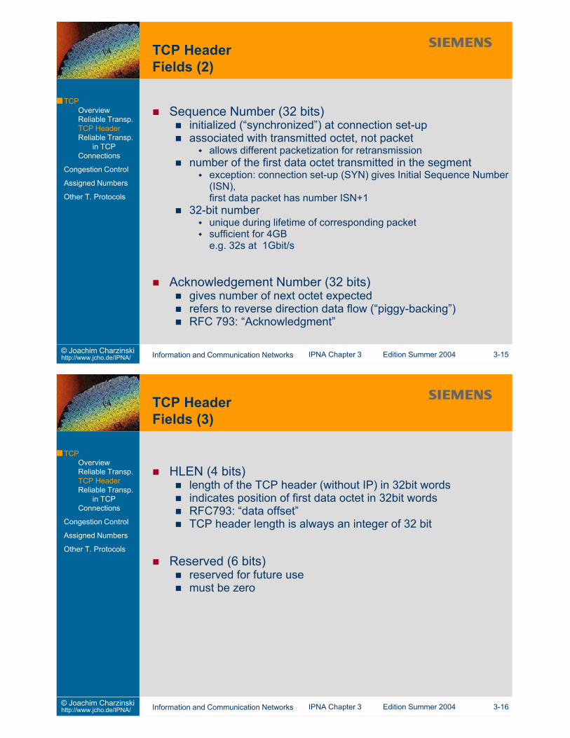
32 bit Sequence and Acknowledgement Numberscumulative acknowledgements
ACK gives “next octet expected”i.e. acknowledgement of all contiguously received octetssegments received after lost packet cannot be acknowledged[NACK would be possible here!]
Retransmission if acknowledgement is missing after timeoutadaptive timeout trying to follow network delay (route and loadchange)avoid unnecessary timeoutsallow fastest possible reaction to loss
Retransmission can include more data than the originalsegment!
Efficient computationchoose inverse powers of 2 for δ and ρperform integer arithmetic by scaling correspondinglye.g. δ=1/8, ρ=1/4, η=2 or 4,scale results by factor of 8
Acknowledgement AmbiguityIn the case of a retransmission, does the ACK correspond toa) the original orb) the retransmitted segment?a) leads to unbounded growth due to increased timeoutsb) can lead to a steady state of retransmission time < RTT
(all segments are transmitted multiple timeseven without any loss)
Consequence: No RTT update with retransmitted segments!Karn’s Algorithm:update RTT estimates with unambiguous ACKs only
in addition: Timer backoffincrease timer value for retransmission when timer expires
new timeout = γ * computed timeout
γ = 2 (increase retransmission stability)with upper boundreset to normal estimate for next unambiguous ACK
Receiver Flow Controladapt sender data rate to receiver speedprevent buffer overflow at receiverreceiver advertises available buffer space
Network Congestion Controlavoid network overloadprevent packet loss at router buffers in the network“fair sharing” of rates between all TCP connectionson a bottleneck link“elastic traffic”: connection bit rate variesaccording to available capacityTCP traffic cannot adequately be described by a rate profile
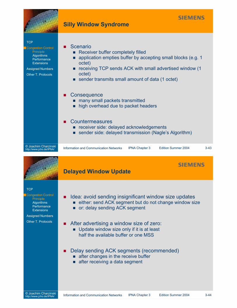
ScenarioReceiver buffer completely filledapplication empties buffer by accepting small blocks (e.g. 1octet)receiving TCP sends ACK with small advertised window (1octet)sender transmits small amount of data (1 octet)
Consequencemany small packets transmittedhigh overhead due to packet headers
Send an ACK packet only ifreceive window has significantly changed (see 3-44) or500ms have passed since a segment to be acknowledged hasarrived oranother segment has arrived beforeand has not been acknowledged yet
→ Increase chance of piggybacking ACK on answer packetcharacter echo in telnet etc.protocol response in ftp-control, http etc.
→ Increase chance of ACK updating the window size→ Decrease network traffic due to ACK packets
cumulative ACK
Disadvantagesincreased chance of timeoutsaccuracy of RTT estimates reduced due to fewer samples
TCP collects data before transmitting a segmentwait long enough to limit overheadtransmit fast enough to ensure deliveryif higher level protocol is waiting
Nagle’s Algorithmput data into output bufferIf still waiting for an ACK, wait until
MSS can be filled orACK arrives
Do this even if PUSH was requested
This algorithm is self-clockingsimple operationno need for extra timer
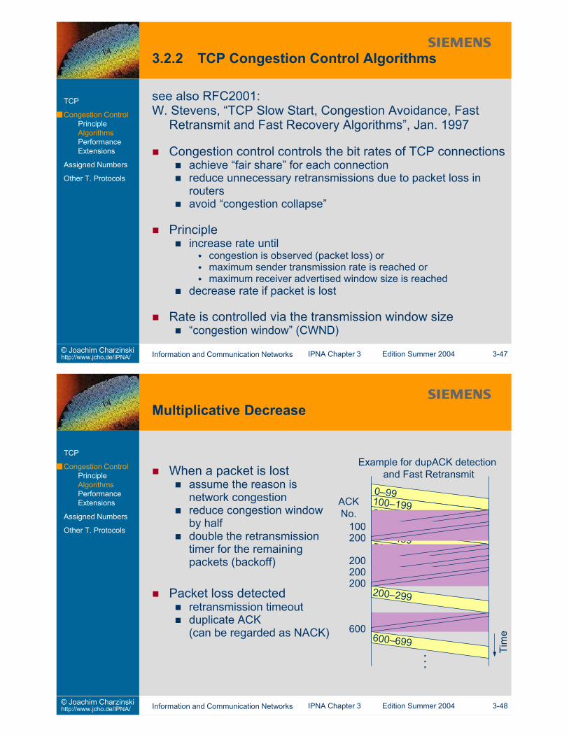
see also RFC2001:W. Stevens, “TCP Slow Start, Congestion Avoidance, Fast
Retransmit and Fast Recovery Algorithms”, Jan. 1997
Congestion control controls the bit rates of TCP connectionsachieve “fair share” for each connectionreduce unnecessary retransmissions due to packet loss inroutersavoid “congestion collapse”
Principleincrease rate until
congestion is observed (packet loss) ormaximum sender transmission rate is reached ormaximum receiver advertised window size is reached
decrease rate if packet is lost
Rate is controlled via the transmission window size“congestion window” (CWND)
When a packet is lostassume the reason isnetwork congestionreduce congestion windowby halfdouble the retransmissiontimer for the remainingpackets (backoff)
Packet loss detectedretransmission timeoutduplicate ACK(can be regarded as NACK)
Limit exponential growth of congestion window“Threshold” = half the window size before previous lossSSTHRESH = CWND/2When threshold is reached:increase window by 1 segment only when all segments in thewindow have been acknowledgedlinear increase of the window over time
Window size computed in octets, not packetsincrease by MSS in slow start phaseincrease by MSS * MSS / windowSizein congestion avoidance phase
start at CWND = MSSCongestion Avoidance after CWND reaching threshold valueSSTHRESHFast Retransmit
after number of duplicate ACKs (e.g. 3),retransmit segments without waiting for timeoutset SSTHRESH = CWND / 2perform slow start: set CWND = MSS
Renolike Tahoeplus Fast Recovery
after receiving dup ACKs (usually 3)Fast Retransmit (reduce CWND by half)schedule transmissions according to incoming ACKswindow size = min(AWIN, CWND+nDUP)
ACK AcknowledgementAWIN Advertised WindowCWND Congestion WindownDUP number of duplicate ACKs
New Renochange in “partial ACK” handling during Fast Recoveryretain Fast Recovery status even if a second packet was lostreduce CWND by half only once
SACKTCP Option (header extension) to allow selectiveacknowledgementsonly retransmit the lost segmentsallows retransmitting more than one segment per RTT
Problem without SACK:either retransmit segments already successfully receivedor retransmit at most one segment per RTT
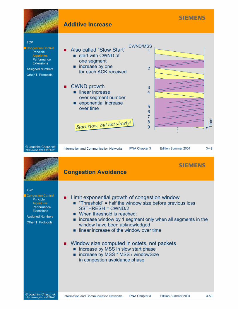
Tahoe, Reno, SACKuse additive increase and multiplicative decreasesense congestion only through packet loss (timeout or dupACK)
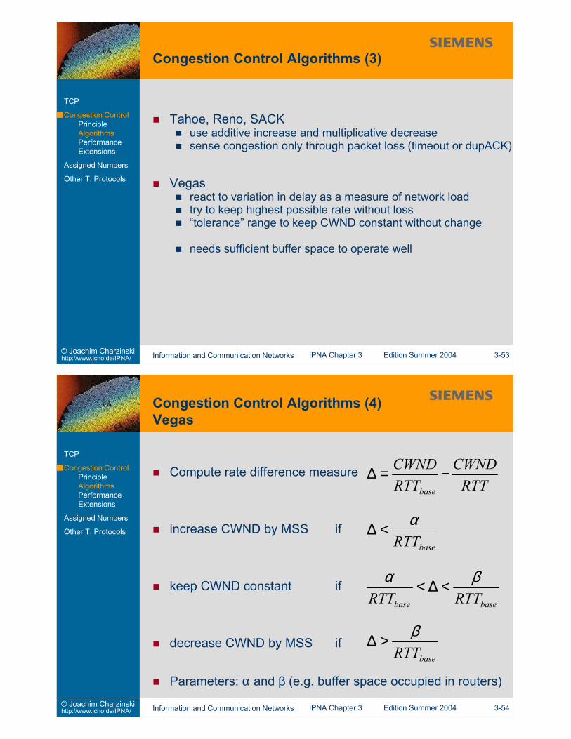
Vegasreact to variation in delay as a measure of network loadtry to keep highest possible rate without loss“tolerance” range to keep CWND constant without change
Formula derived by Mathis, Semke, Mahdavi, OttM. Mathis, J. Semke, J. Mahdavi, T. Ott,
“The Macroscopic Behavior of the TCP Congestion AvoidanceAlgorithm”, ACM Computer Communication Review 27 (3) Jul.1997, available athttp://www.psc.edu/networking/papers/model_ccr97.ps(last checked April 2003)
Mean Congestion Window size
Mean Steady State Throughput (in packets per time)
Explicit Congestion Notification (ECN)set an “ECN” bit instead of dropping packets
set ECN bit if buffer levels are above a threshold,so additional packets can still be stored
control TCP congestion window without requiringretransmissionreverse transmission neededneeds support in routers and end systems
Random Early Detection (RED)avoid source synchronisation by introducing queue thresholdto randomly drop packetsindependent implementation in routers (“IP gateways”)performance improvement depends on scenario (questionable)
Port (dec.) keyword description0 – reserved7 echo echo what is received9 discard discard all received information13 daytime answer with date and time19 chargen character generator20 ftp data File Transfer Protocol data connections21 ftp FTP control connections23 telnet telnet server25 smtp Simple Mail Transfer Protocol: Mail server53 domain Domain Name Server (DNS)67 bootps bootp or DHCP server68 bootpc bootp or DHCP client69 tftp trivial file transfer protocol70 gopher gopher (text based predecessor of the Web)80 http Hypertext Transport Protocol server88 kerberos Kerberos security service
Port (dec.) keyword description110 pop3 Post Office Protocol version 3119 nntp Network News Transfer Protocol123 ntp Network Time Protocol137, 138, 139 netbios Netbios Name, Datagram and Session Services177 xdmcp X Display Manager Control Protocol443 https Secure Socket Layer HTTP6000 X11 X Window
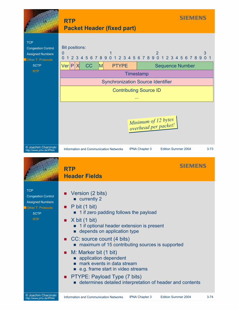
Sequence Number (16 bits)identifies RTP packetsinitial sequence number chosen randomly for each session
Timestamp (32 bits)time at which the first octet of digitized data was sampled(relative)random choice of initial time stampcontinuously incrementedclock granularity depends on application
Synchronization Source Identifier (32 bits)identifies the source of a streamreal source, mixer or translatoridentification collisions resolved by protocol
Contributing Source ID (variable size, CC x 32 bits)list of source identifiers that contributed the samples mixedtogether by a mixer
3.1 Can two TCP applications establish a connection if they bothissue an “active” open call? (Hint: Check the TCP connectionstate diagram)
3.2 Can an application open two parallel TCP connections to thesame server at the same server port?
3.3 Collect all the well-known port numbers for the protocolsshown on slide 2-11.Does each protocol have an assigned number?What would happen if a server offered a protocolon another than the well-known port?
3.4 How is message delineation done in SMTP? in HTTP?3.5 What is a “persistent connection” in HTTP?3.6 How can a computer learn its configuration using DHCP?
This slide set is distributed to support students of the University of Stuttgart who attend the IPNA lectureduring summer term 2004. All other use requires written permission by Joachim Charzinski.
1. Introduction2. Network Layer (et al.)3. Transport Layer4. Applications and Application Layer Protocols5. Network Architectures6. Statistics and Performance7. Quality of Service8. Network Management9. Security
TCP transfers an octet streammapping of protocol messages into packets is not reliable
PUSH mechanism may still deliver multiple messages perpacket (see Nagle’s algorithm in Sec. 3.2.1)messages may be longer than MSS and split across packets→ multiple packets’ payloads must be concatenated
→ messages must be delineated within the octet stream“end-of-line” codes
mostly for ASCII text message based protocolsone message per “line”“end-of-line” must be defined, e.g. as the [CR][LF] sequenceexamples: HTTP, SMTP, POP, IMAP
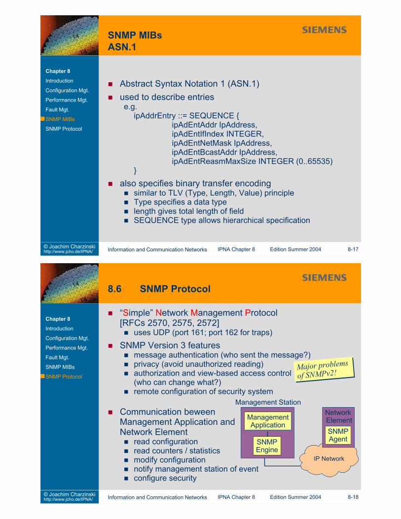
“type-length-value” (TLV) encodingalso used in the IP and TCP options header fieldsexample: SNMP (doing it with ASN.1, see Sec. 8.6)
use separate connections for control and user dataconnection endpoints must communicate aboutuser data connections to open and closeaddresses and port numbers exchanged between endpoints
→ problems with NAT, firewalls and IPv4/v6 transitionexamples: FTP, H.323, SIP (voice over IP)
special character sequences separate control and user datacharacter sequence must be escaped if it occurs in user dataexample: SMTP using “a period on a single line by itself”
content length encodingspecify content length of user data in control messagescontent length must be known in advanceeasy to get desynchronized
non-transparent networks (should not be a problem anymore)lazy programmers might mis-calculate lengths
example: HTTPIf the content length was unknown before transmission (e.g. indynamically created pages), the HTTP server closes theconnection to mark the end of a transferred element.
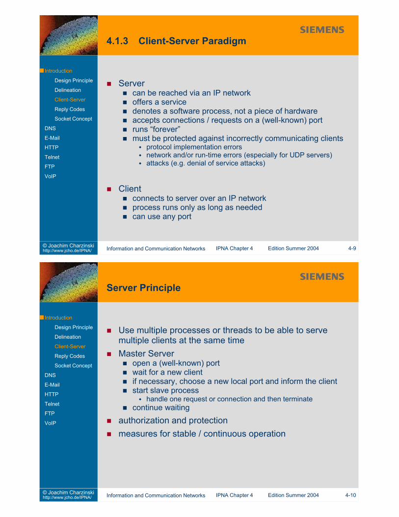
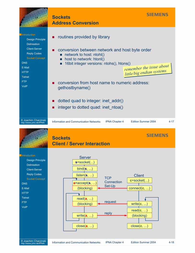
Servercan be reached via an IP networkoffers a servicedenotes a software process, not a piece of hardwareaccepts connections / requests on a (well-known) portruns “forever”must be protected against incorrectly communicating clients
protocol implementation errorsnetwork and/or run-time errors (especially for UDP servers)attacks (e.g. denial of service attacks)
Clientconnects to server over an IP networkprocess runs only as long as neededcan use any port
Information204 No Content205 Reset Content206 Partial Content300 Multiple Choices301 Moved Permanently302 Found303 See Other304 Not Modified305 Use Proxy307 Temporary Redirect400 Bad Request401 Unauthorized402 Payment Required403 Forbidden
404 Not Found405 Method Not Allowed406 Not Acceptable407 Proxy Authentication
Required408 Request Time-out409 Conflict410 Gone411 Length Required412 Precondition Failed413 Request Entity Too Large414 Request-URI Too Large415 Unsupported Media Type416 Requested range
not satisfiable417 Expectation Failed500 Internal Server Error501 Not Implemented502 Bad Gateway503 Service Unavailable504 Gateway Time-out505 HTTP Version not supported
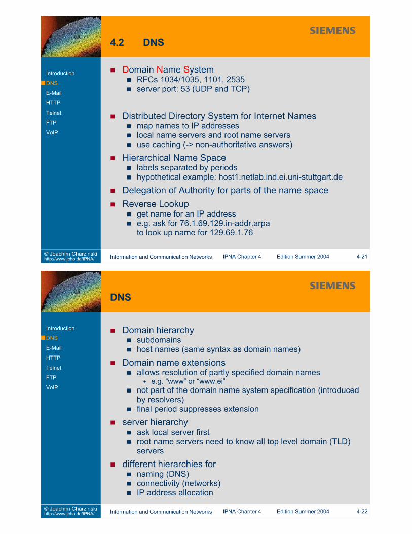
Domain Name SystemRFCs 1034/1035, 1101, 2535server port: 53 (UDP and TCP)
Distributed Directory System for Internet Namesmap names to IP addresseslocal name servers and root name serversuse caching (-> non-authoritative answers)
Hierarchical Name Spacelabels separated by periodshypothetical example: host1.netlab.ind.ei.uni-stuttgart.de
Delegation of Authority for parts of the name spaceReverse Lookup
get name for an IP addresse.g. ask for 76.1.69.129.in-addr.arpato look up name for 129.69.1.76
Domain names stored as sequence of “labels”succession of 1 octet length n and n octets label (ASCII)length = 0: end of namelabels restricted to 63 characters (top 2 bits of length value arezeroes)
Label00 Length 00 Length Label 00000000
11 Pointer
Repetition of domain names in packets avoided by pointersif top 2 bits of length value are set to one,interpret the following 14 bits as a pointer(offset from start of message; 0 = first octet of ID field)
Multi-hop deliveryto build address hierarchy, hide local addresses in privatenetworksto have central mail gateway e.g. for an organisationto perform central filtering functions, e.g. Virus removal
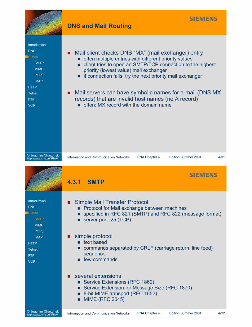
Mail client checks DNS “MX” (mail exchanger) entryoften multiple entries with different priority valuesclient tries to open an SMTP/TCP connection to the highestpriority (lowest value) mail exchangerif connection fails, try the next priority mail exchanger
Mail servers can have symbolic names for e-mail (DNS MXrecords) that are invalid host names (no A record)
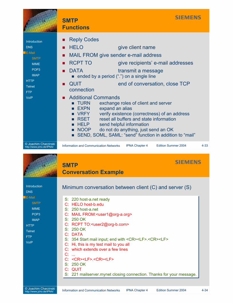
Reply CodesHELO give client nameMAIL FROM give sender e-mail addressRCPT TO give recipients’ e-mail addressesDATA transmit a message
ended by a period (“.”) on a single lineQUIT end of conversation, close TCPconnectionAdditional Commands
TURN exchange roles of client and serverEXPN expand an aliasVRFY verify existence (correctness) of an addressRSET reset all buffers and state informationHELP send helpful informationNOOP do not do anything, just send an OKSEND, SOML, SAML: “send” function in addition to “mail”
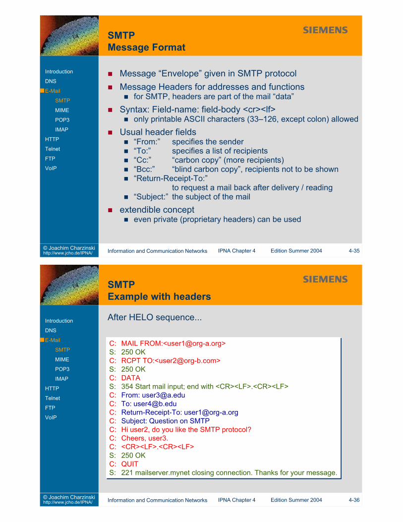
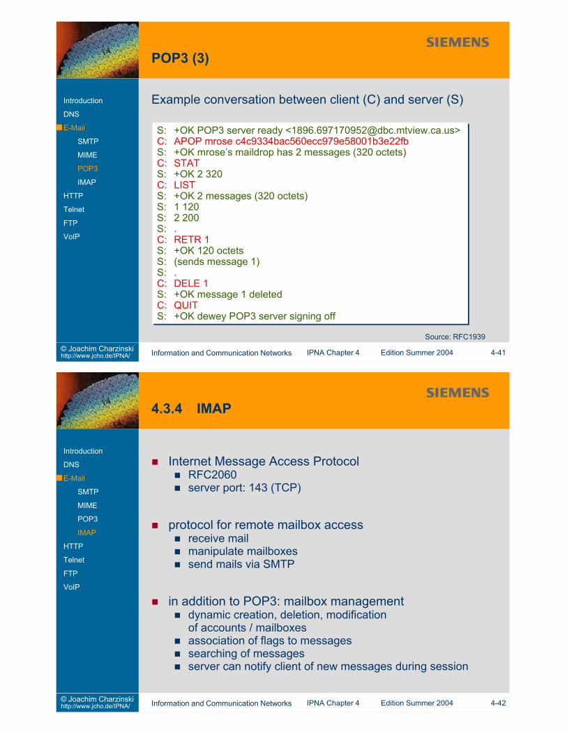
Minimum conversation between client (C) and server (S)
S: 220 host-a.net readyC: HELO host-b.eduS: 250 host-a.netC: MAIL FROM:<[email protected]>S: 250 OKC: RCPT TO:<[email protected]>S: 250 OKC: DATAS: 354 Start mail input; end with <CR><LF>.<CR><LF>C: Hi, this is my test mail to you allC: which extends over a few linesC: ...C: <CR><LF>.<CR><LF>S: 250 OKC: QUITS: 221 mailserver.mynet closing connection. Thanks for your message.
S: 220 host-a.net readyC: HELO host-b.eduS: 250 host-a.netC: MAIL FROM:<[email protected]>S: 250 OKC: RCPT TO:<[email protected]>S: 250 OKC: DATAS: 354 Start mail input; end with <CR><LF>.<CR><LF>C: Hi, this is my test mail to you allC: which extends over a few linesC: ...C: <CR><LF>.<CR><LF>S: 250 OKC: QUITS: 221 mailserver.mynet closing connection. Thanks for your message.
Message “Envelope” given in SMTP protocolMessage Headers for addresses and functions
for SMTP, headers are part of the mail “data”Syntax: Field-name: field-body <cr><lf>
only printable ASCII characters (33–126, except colon) allowedUsual header fields
“From:” specifies the sender“To:” specifies a list of recipients“Cc:” “carbon copy” (more recipients)“Bcc:” “blind carbon copy”, recipients not to be shown“Return-Receipt-To:”
to request a mail back after delivery / reading“Subject:” the subject of the mail
extendible concepteven private (proprietary headers) can be used
C: MAIL FROM:<[email protected]>S: 250 OKC: RCPT TO:<[email protected]>S: 250 OKC: DATAS: 354 Start mail input; end with <CR><LF>.<CR><LF>C: From: [email protected]: To: [email protected]: Return-Receipt-To: [email protected]: Subject: Question on SMTPC: Hi user2, do you like the SMTP protocol?C: Cheers, user3.C: <CR><LF>.<CR><LF>S: 250 OKC: QUITS: 221 mailserver.mynet closing connection. Thanks for your message.
C: MAIL FROM:<[email protected]>S: 250 OKC: RCPT TO:<[email protected]>S: 250 OKC: DATAS: 354 Start mail input; end with <CR><LF>.<CR><LF>C: From: [email protected]: To: [email protected]: Return-Receipt-To: [email protected]: Subject: Question on SMTPC: Hi user2, do you like the SMTP protocol?C: Cheers, user3.C: <CR><LF>.<CR><LF>S: 250 OKC: QUITS: 221 mailserver.mynet closing connection. Thanks for your message.
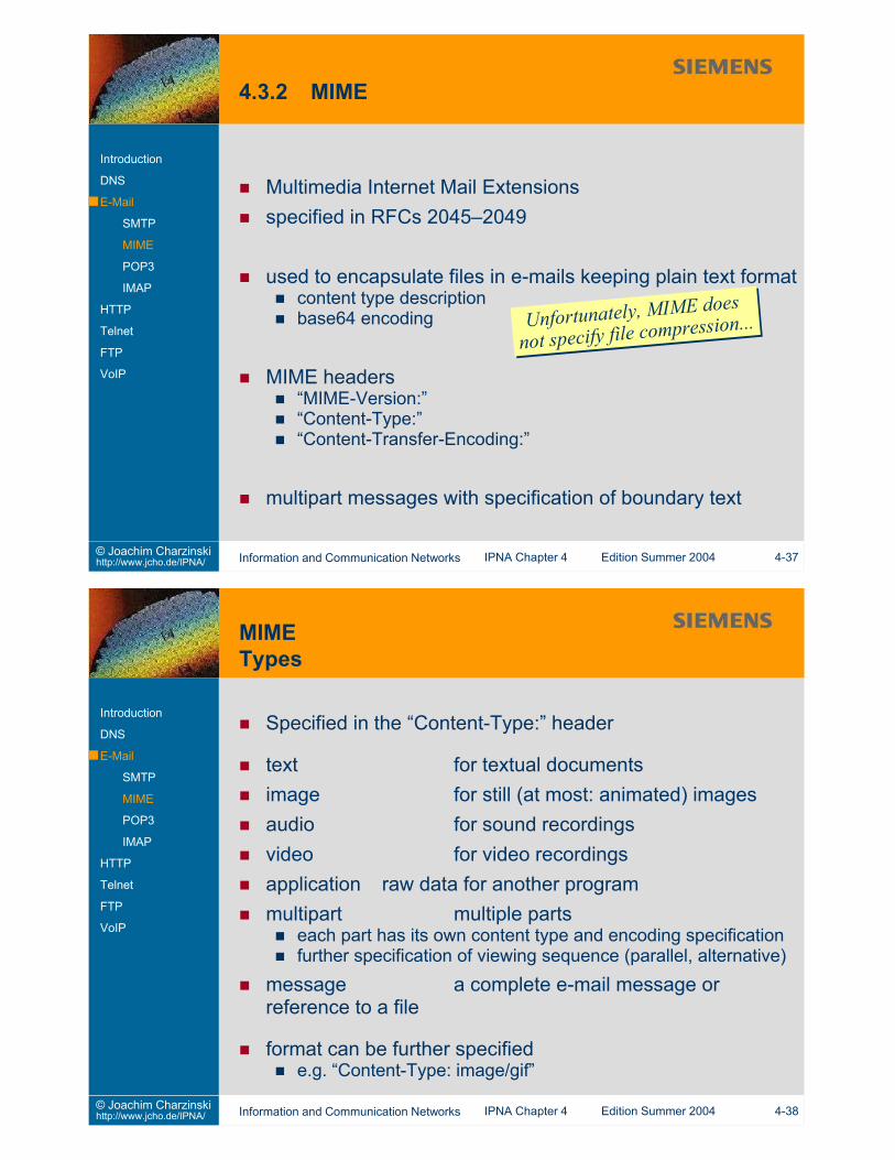
text for textual documentsimage for still (at most: animated) imagesaudio for sound recordingsvideo for video recordingsapplication raw data for another programmultipart multiple parts
each part has its own content type and encoding specificationfurther specification of viewing sequence (parallel, alternative)
message a complete e-mail message orreference to a file
format can be further specifiede.g. “Content-Type: image/gif”
Client commands3 or four characters ASCII, case insensitivearguments separated by a single space characterup to 40 characters per argumenttermination by CRLF
Server responsesstatus indicator (“+OK” or “-ERR”)additional information (max. 512 characters total)multi-line response terminated by CRLF.CRLF
Authorization Statecommands: USER+PASS or APOP or QUIT
Internet Message Access ProtocolRFC2060server port: 143 (TCP)
protocol for remote mailbox accessreceive mailmanipulate mailboxessend mails via SMTP
in addition to POP3: mailbox managementdynamic creation, deletion, modificationof accounts / mailboxesassociation of flags to messagessearching of messagesserver can notify client of new messages during session
FTP File Transfer ProtocolHTML Hypertext Markup LanguageMIME Multipurpose Internet Mail ExtensionsNNTP Network News Transfer ProtocolSMTP Simple Mail Transfer ProtocolURL Uniform Resource LocatorWAIS Wide Area Information Service
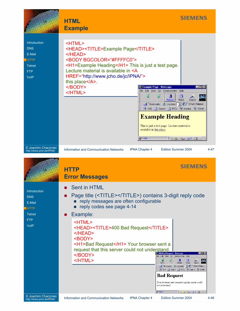
<HTML><HEAD><TITLE>Example Page</TITLE></HEAD><BODY BGCOLOR=“#FFFFC0”><H1>Example Heading</H1> This is just a test page.Lecture material is available in <AHREF=“http://www.jcho.de/jc/IPNA/”>this place</A>.</BODY></HTML>
<HTML><HEAD><TITLE>Example Page</TITLE></HEAD><BODY BGCOLOR=“#FFFFC0”><H1>Example Heading</H1> This is just a test page.Lecture material is available in <AHREF=“http://www.jcho.de/jc/IPNA/”>this place</A>.</BODY></HTML>
Sent in HTMLPage title (<TITLE></TITLE>) contains 3-digit reply code
reply messages are often configurablereply codes see page 4-14
Example:<HTML><HEAD><TITLE>400 Bad Request</TITLE></HEAD><BODY><H1>Bad Request</H1> Your browser sent arequest that this server could not understand.</BODY></HTML>
<HTML><HEAD><TITLE>400 Bad Request</TITLE></HEAD><BODY><H1>Bad Request</H1> Your browser sent arequest that this server could not understand.</BODY></HTML>
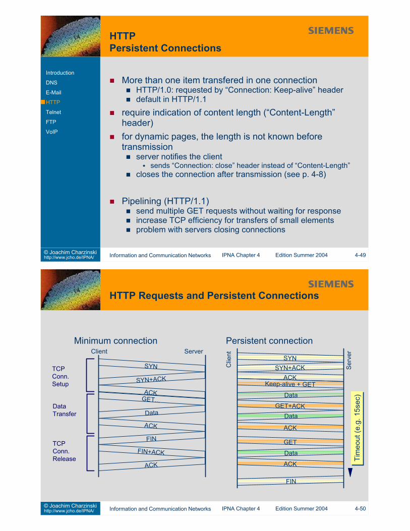
More than one item transfered in one connectionHTTP/1.0: requested by “Connection: Keep-alive” headerdefault in HTTP/1.1
require indication of content length (“Content-Length”header)for dynamic pages, the length is not known beforetransmission
server notifies the clientsends “Connection: close” header instead of “Content-Length”
closes the connection after transmission (see p. 4-8)
Pipelining (HTTP/1.1)send multiple GET requests without waiting for responseincrease TCP efficiency for transfers of small elementsproblem with servers closing connections
Terminal and process control are usually vendor specifice.g. end of line by CR (carriage return), LF (line feed) or bothe.g. program interrupt by Control-C, Escape, Stop...
Network Virtual Terminal defines transmission across theInternet
specific formats are used on client and server sideconverted into NVT format and back
ASCII Dec. Name OperationNUL 0 no operationBEL 7 bell audible/visible signalBS 8 backspace move left one character positionHT 9 hor. Tab move right to next horizontal tabulator positionLF 10 line feed move vertically down to the next lineVT 11 vert. Tab move down to next vertical tabulator positionFF 12 form feed move to top of next pageCR 13 carriage return move to left margin of current lineother ignored
Signal OperationIP Interrupt Process: terminate running programAO Abort Output: discard any buffered outputAYT Are You There: request response from serverEC Erase Character: delete the previous characterEL Erase Line: entirely delete the current lineSYNCH Synchronize: clear data until TCP urgent point
but interpret commands (concept)BRK Break: break key or attention signal
IAC (interpret as control) character reserved as escapesequence
indicate that a control octet followsCommand Dec. FunctionIAC 255 interpret next octet as commandEOR 239 end of recordSE 240 end of option subnegotiationNOP 241 no operationDMARK 242 data stream portion of a SYNCH signal
(with TCP Urgent notification)BRK 243 NVT Break signalIP 244 NVT Interrupt Process signalAO 245 NVT Abort Output signalAYT 246 NVT Are You There signalEC 247 NVT Erase Character signalEL 248 NVT Erase Line signalGA 249 Go AheadSB 250 start of option subnegotiationWILL 251 agree to perform specified optionWON’T 252 refuse to perform specified optionDO 253 allow specified optionDON’T 254 deny to perform specified option requested
Telnet options are negotiated between client and serversymmetric negotiation (client or server can make a request)extendible (anyone can refuse to use or let use unknownoptions)
Negotiation: WILL/WONT, DO/DONTtwo-way negotiationdo not acknowledge options already in use
A->B: WILL xA wants to use option xB->A: DO x (ok) or DONT x (not ok)
A->B: DO xA wants B to use option xB->A: WILL x (ok) or WONT x (not ok)
Option Code RFC ExplanationTransmit Binary 0 856 Change transmission to 8-bit binaryEcho 1 857 process echoes the data it receivesSuppress-GA 3 858 do not send Go-Ahead signal after dataStatus 5 859 request the status of a Telnet OptionTiming-Mark 6 860 request timing mark to be inserted
in return streamTerminal-Type 24 884 terminal type information to allow
programs to use advanced terminalfeatures(cursor positioning, optimisation, colors)
End-of-Record 25 885 terminate data with EOR codeLinemode 34 1116 send complete line after local editing
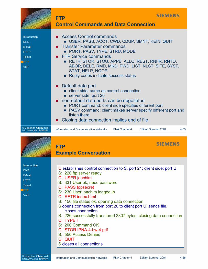
Default data portclient side: same as control connectionserver side: port 20
non-default data ports can be negotiatedPORT command: client side specifies different portPASV command: client makes server specify different port andlisten there
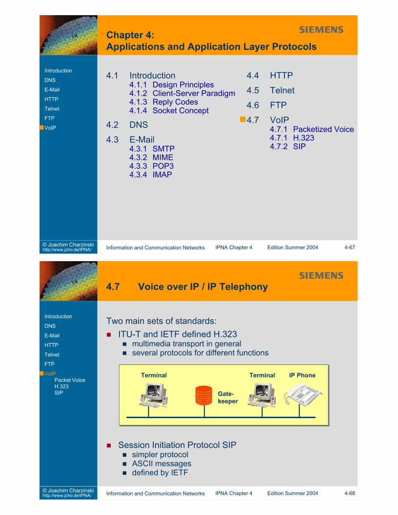
C establishes control connection to S, port 21; client side: port US: 220 ftp server readyC: USER joachimS: 331 User ok, need passwordC: PASS topsecretS: 230 User joachim logged inC: RETR index.htmlS: 150 file status ok, opening data connectionS opens connection from port 20 to client port U, sends file,
closes connectionS: 226 successfully transfered 2307 bytes, closing data connectionC: TYPE IS: 200 Command OKC: STOR IPNA-4-bw-4.pdfS: 550 Access DeniedC: QUITS closes all connections
H.450: additional featuresH.450.1: common protocol for service / features supportH.450.2ff: description of features,e.g. call transfer, holdlike private branch exchange (PBX) features
H.235: security
H.246: interworking with circuit switched networks
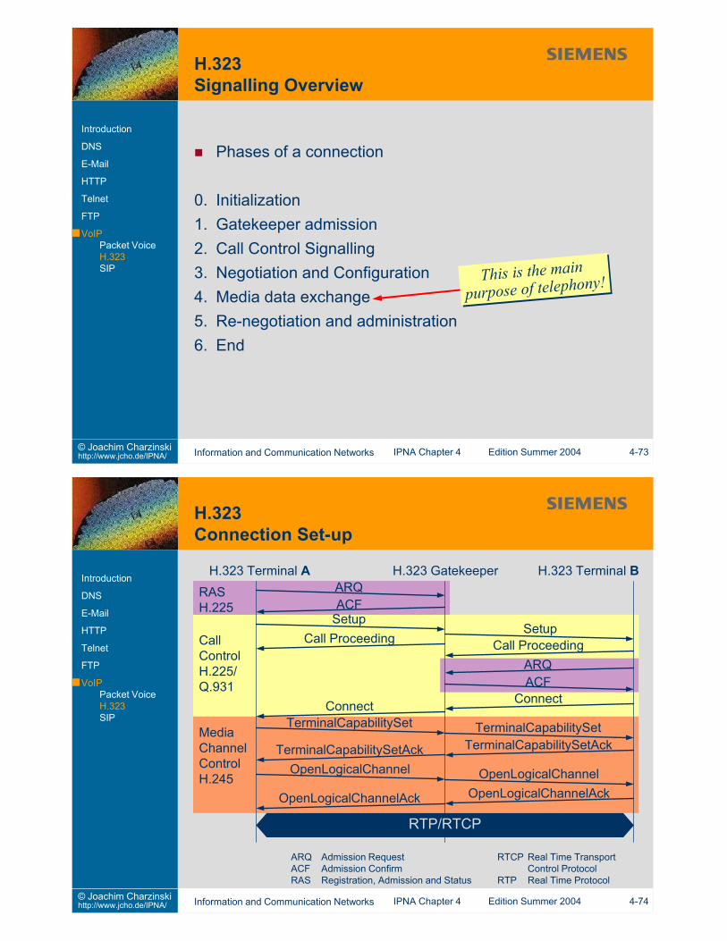
0. Initialization1. Gatekeeper admission2. Call Control Signalling3. Negotiation and Configuration4. Media data exchange5. Re-negotiation and administration6. End
4.1 Determine the name and address of the authoritative nameserverfor “ei.uni-stuttgart.de” using “nslookup” or “dig”.
4.2 Use nslookup to determine the host name for IP address129.69.1.76 .
4.3 What hosts are mail exchangers for “jcho.de”?4.4 Write a simple SMTP client and test if it can deliver a mail
message.(Handle only the “good” case.)
4.5 Telnet to a Web server (port 80) and retrieve a Web page.Can you make the server not close the connection immediately?How long does it take until the server closes the connection?
4.6 Play with the Web server from Section 4.1.4.
4.7 What is Network Address Translation (NAT)?4.8 What is the Hurst Parameter?4.9 How would you measure Internet quality?4.10 What is the difference between the IntServ and DiffServ
This slide set is distributed to support students of the University of Stuttgart who attend the IPNA lectureduring summer term 2004. All other use requires written permission by Joachim Charzinski.
1. Introduction2. Network Layer (et al.)3. Transport Layer4. Applications and Application Layer Protocols5. Network Architectures6. Statistics and Performance7. Quality of Service8. Network Management9. Security
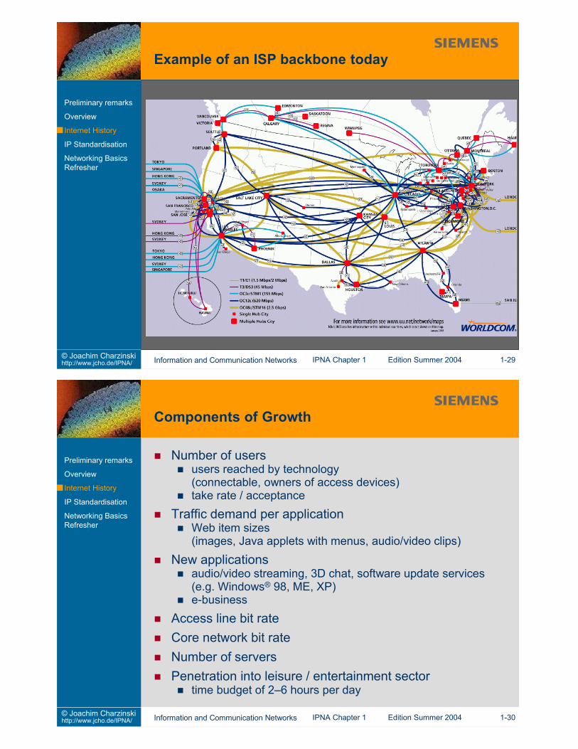
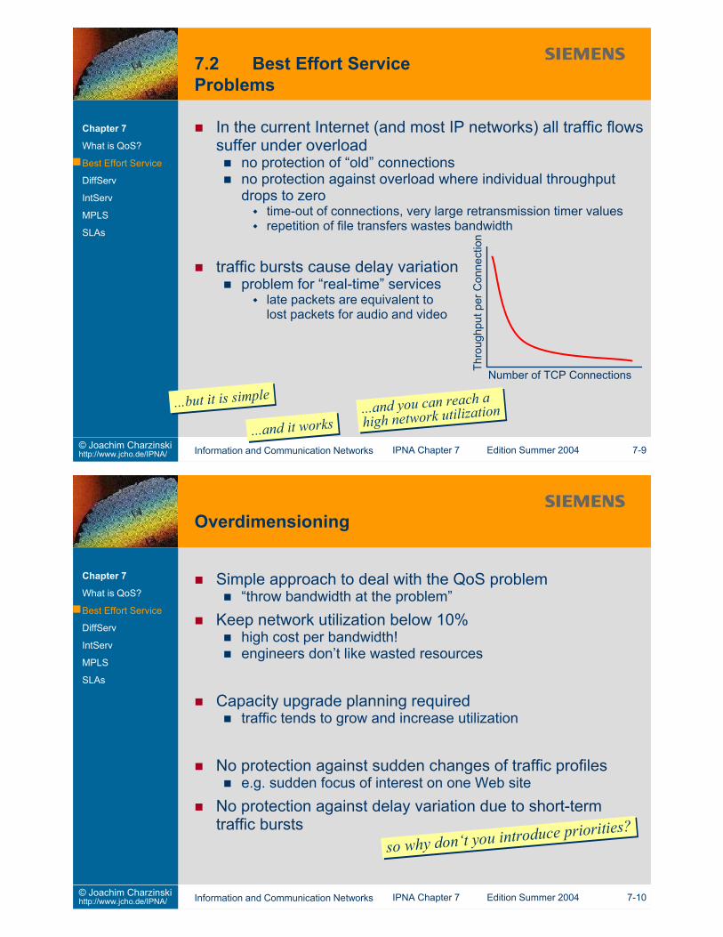
Worldwide connectivityISPs connect private and business usersprivate: mostly dial-up connectionsbusiness: mostly always-on connectionsplus: academic networks (part of the Internet)
Structurelarge ISPs have their own world-wide backbone networks(leased lines interconnecting routers)smaller ISPs have peering agreements with large ISPs totransport wide area trafficmost traffic to or from outside networks
efforts (e.g. portals) to keep more traffic within own network
IP is used outside the Internetother “IP Networks”
Reasonsubiquitous availability of IP in end systemsIP network components (routers) offer high throughput per $simple configuration and cheap subnetwork components(hubs, switches)
Integration of servicese.g. voice and databandwidth sharing between traffic typessave on operating personnel by unified network technology
→ IP is being introduced into “classical” telecommunicationnetworks
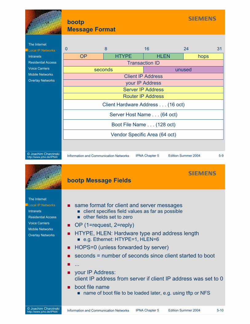
same format for client and server messagesclient specifies field values as far as possibleother fields set to zero
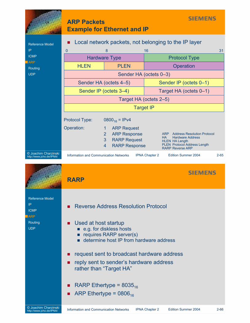
OP (1=request, 2=reply)HTYPE, HLEN: Hardware type and address length
e.g. Ethernet: HTYPE=1, HLEN=6HOPS=0 (unless forwarded by server)seconds = number of seconds since client started to boot...your IP Address:client IP address from server if client IP address was set to 0boot file name
name of boot file to be loaded later, e.g. using tftp or NFS
Dynamic Host Configuration Protocol [RFC 2131]extension of bootp
more information in returned messagee.g. subnet mask
optional automatic or dynamic IP address assignmentserver selects IP address from a pool of free addressesmulti-step procedure
limited-time lease of an IP address to a clientclient wishes and server grants lease durationclient requests renewal after 50% of lease durationearly lease termination is possible
static address assignment with DHCPserver knows client’s hardware address (configured by networkmanager)grants very long (or infinite) lease of address
Internal IP networks (e.g. of a company)full internal IP connectivityoften with internal DNS name space, DNS servers etcoften interconnecting multiple sites in the worldexternal connectivity to Internet
via NAT, application proxies, firewalls, gateways
often with private address range (e.g. 10.0.0.0 network)or duplicate of a valid Internet address range (connectivityproblems!)problems with company mergers!
Internal servicesusually not exported to external worldexported services with access limitation → “Extranets”
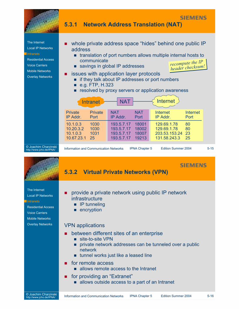
whole private address space “hides” behind one public IPaddress
translation of port numbers allows multiple internal hosts tocommunicatesavings in global IP addresses
issues with application layer protocolsif they talk about IP addresses or port numberse.g. FTP, H.323resolved by proxy servers or application awareness
PrivateIP Addr.
10.1.0.310.20.3.210.1.0.310.67.23.1
PrivatePort
10301030103125
NATIP Addr.
193.5.7.17193.5.7.17193.5.7.17193.5.7.17
NATPort
18001180021800719213
InternetIntranet NAT
InternetIP Addr.
129.69.1.78129.69.1.78203.53.153.24131.58.243.3
InternetPort
80802325
recompute the IPheader checksum!recompute the IPheader checksum!
Private modem pool and access server within Intranetlong-distance dial-up connectionsinformation security relies on telephone network
VPN based accessuse IP tunnel over the Internet or from a VPN providerencryption of data in tunnel ensures information securityworld-wide ISP presence allows local calls for dial-upconnections
Media Gatewayconversion between voice formatsusing DSPs
traditional networkPCM voiceISDN
IP networkG.711, G.723, etc for voice codingsee Sec. 4.5.1
Media Gateway Controller (MGC)conversion between IP and POTS/ISDNsignallingIP side: H.323, SIPPOTS side: SS7, PBX protocolscontrol of media gateway (e.g. MEGACO)
PBX Private Branch ExchangePCM Pulse Code ModulationPOTS Plain Old Telephony ServiceSIP Session Initiation ProtocolSS7 Signalling System #7
DSP Digital Signal ProcessorISDN Integrated Services Digital NetworkMEGACO Media Gateway Control ProtocolMGC Media Gateway Controller
Difference between wireless technology and mobility!wireless technology: communicate while movingwire bound technology: plug into a new network and continueworking
Mobile IP specifies mobility support(more or less) independent of access technologytransparent support (independent of communication partners)for IPv4mobility across the Internet (scalable in terms of distance)
advertisement / broadcast based forwarding managementfor infrequent changes of location
mobility of mobile node MN supportedno need for communication partner (Correspondent Node,CN) to know about thisCN still sends packets to home address of MNminimum requirement: Home Agent (HA)MN can act as Foreign Agent (FA)
MN HA R FA
HomeNetwork
ForeignNetwork
CN Correspondent NodeFA Foreign AgentHA Home AgentMN Mobile NodeR Router
Mobile node connects to foreign networkMN obtains IP address in foreign network (e.g. via dhcp)MN locates foreign agentIPsec tunnel established from Home Agent (HA)to Foreign Agent (FA)IP address of FA is called “care-of” address
packets to the mobile nodereach the home network via standard IP routingare intercepted by the home agenthome agent forwards packet to care-of address within tunnelforeign agent forwards packet to mobile node (no tunnel)
packets from the mobile nodeare sent via standard IP routing to the corresponding node(“triangular routing”)orare sent to the foreign agentforwarded within reverse tunnel to home agentsent to correspondent node by home agent
General Packet Radio Serviceprovide a packet service extension to GSM mobile networks
Protocol Stack:
BSSGP
NetworkServiceL1bis
LLCSNDCP GTP
Relay
L1
L2
IP
UDP /TCP*
GTP
L1
L2
IP
UDP /TCP*
IP/X.25
SGSN GGSN* TCP for X.25, UDP for IP
LLC Logical Link ControlMAC Media Access ControlRLC Radio Link ControlSGSN Serving GPRS Support NodeSNDCP Subnetwork Dependent Convergence Prot.
RLC
MAC
GSM RF
BSSGPNetworkServiceL1bis
Relay
Base Station
ApplicationIP/X.25
SNDCP
LLC
RLC
MAC
GSM RF
Mobile Station
BSSGP Base Station System GPRS ProtocolGGSN Gateway GPRS Support NodeGPRS General Packet Radio ServiceGSM Global System for Mobile CommunicationGTP GPRS Tunnelling Protocol
remove redundancy from IP, UDP, TCP headersnew header compression schemes (rohc working group)
especially for wireless linkscompress RTP and frequently used TCP options (SACK,timestamps)robust to high error rates / packet (frame) lossrobust to long round-trip timesunidirectional links (?)
requirementssemantic identity of header after compression anddecompressionperform well even when the end-to-end path involves multiplewireless linkssupport IPv4 and IPv6
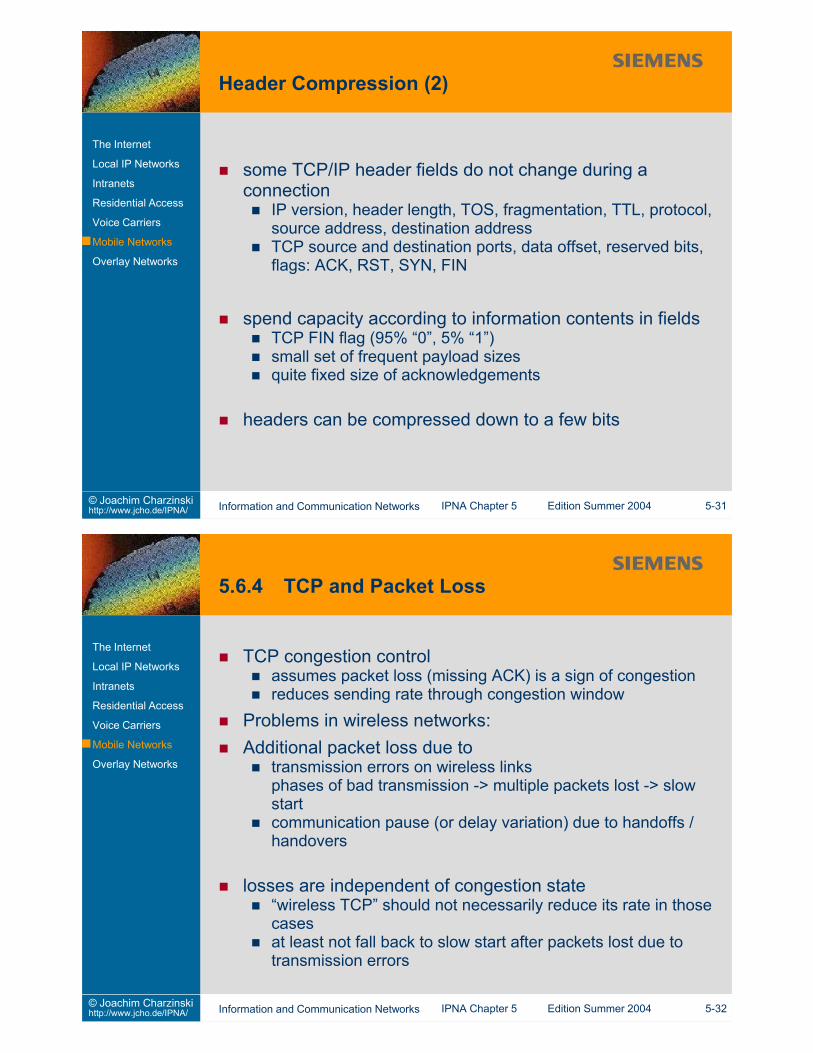
some TCP/IP header fields do not change during aconnection
IP version, header length, TOS, fragmentation, TTL, protocol,source address, destination addressTCP source and destination ports, data offset, reserved bits,flags: ACK, RST, SYN, FIN
spend capacity according to information contents in fieldsTCP FIN flag (95% “0”, 5% “1”)small set of frequent payload sizesquite fixed size of acknowledgements
TCP congestion controlassumes packet loss (missing ACK) is a sign of congestionreduces sending rate through congestion window
Problems in wireless networks:Additional packet loss due to
transmission errors on wireless linksphases of bad transmission -> multiple packets lost -> slowstartcommunication pause (or delay variation) due to handoffs /handovers
losses are independent of congestion state“wireless TCP” should not necessarily reduce its rate in thosecasesat least not fall back to slow start after packets lost due totransmission errors
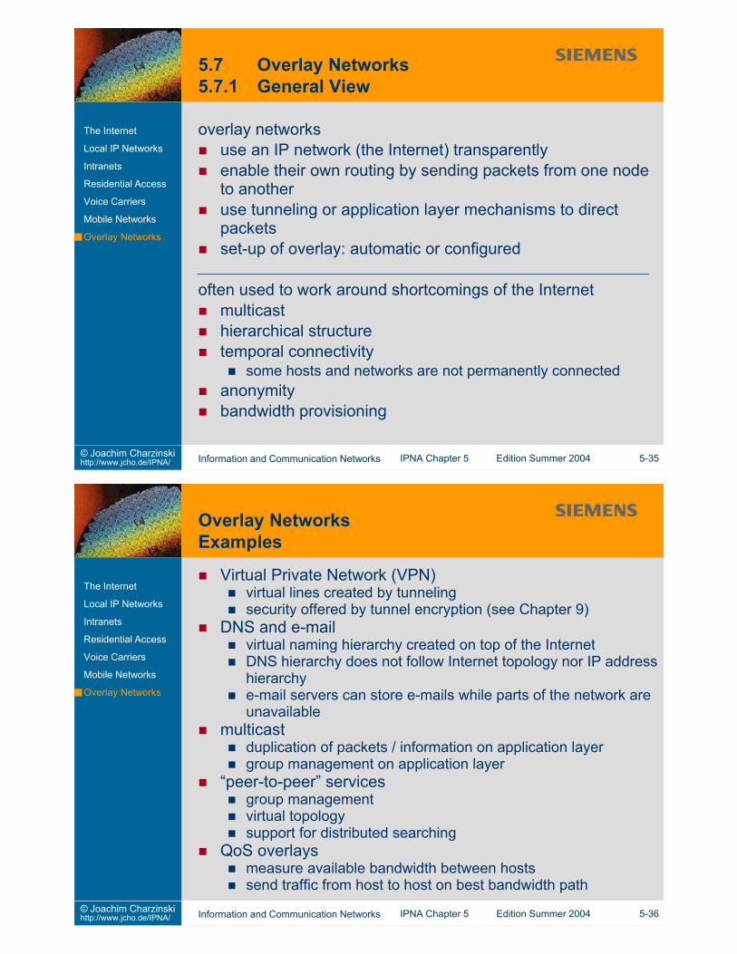
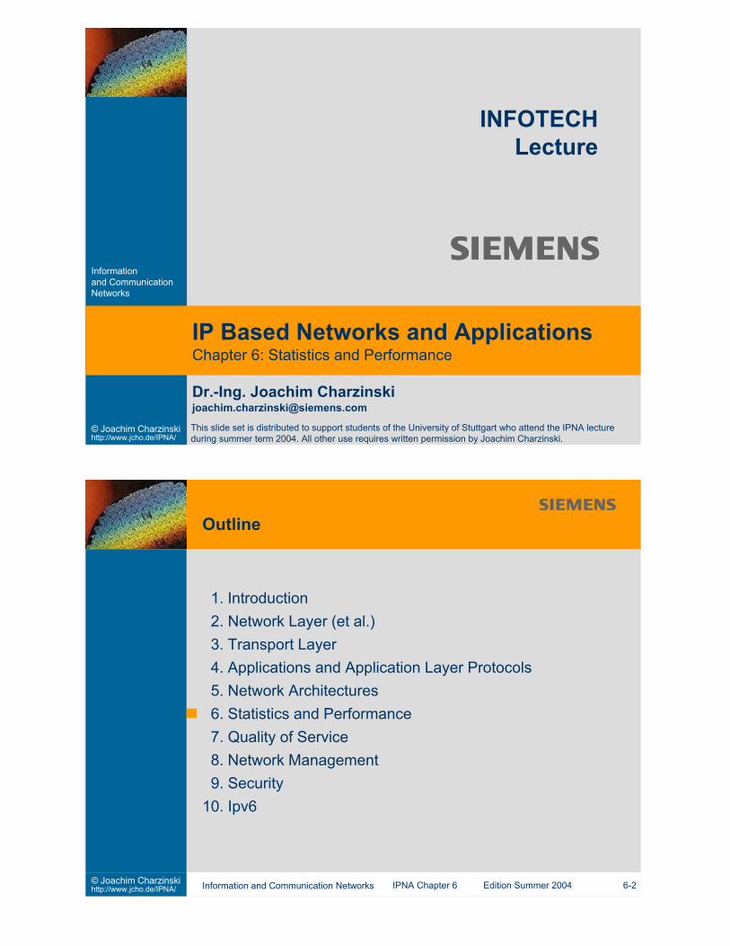
overlay networksuse an IP network (the Internet) transparentlyenable their own routing by sending packets from one nodeto anotheruse tunneling or application layer mechanisms to directpacketsset-up of overlay: automatic or configured
often used to work around shortcomings of the Internetmulticasthierarchical structuretemporal connectivity
some hosts and networks are not permanently connectedanonymitybandwidth provisioning
Virtual Private Network (VPN)virtual lines created by tunnelingsecurity offered by tunnel encryption (see Chapter 9)
DNS and e-mailvirtual naming hierarchy created on top of the InternetDNS hierarchy does not follow Internet topology nor IP addresshierarchye-mail servers can store e-mails while parts of the network areunavailable
multicastduplication of packets / information on application layergroup management on application layer
“peer-to-peer” servicesgroup managementvirtual topologysupport for distributed searching
QoS overlaysmeasure available bandwidth between hosts send traffic from host to host on best bandwidth path
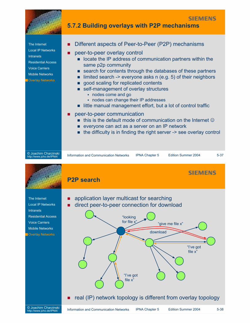
Different aspects of Peer-to-Peer (P2P) mechanismspeer-to-peer overlay control
locate the IP address of communication partners within thesame p2p communitysearch for contents through the databases of these partnerslimited search -> everyone asks n (e.g. 5) of their neighborsgood scaling for replicated contentsself-management of overlay structures
nodes come and gonodes can change their IP addresses
little manual management effort, but a lot of control traffic
peer-to-peer communicationthis is the default mode of communication on the Internet everyone can act as a server on an IP networkthe difficulty is in finding the right server -> see overlay control
This slide set is distributed to support students of the University of Stuttgart who attend the IPNA lectureduring summer term 2004. All other use requires written permission by Joachim Charzinski.
1. Introduction2. Network Layer (et al.)3. Transport Layer4. Applications and Application Layer Protocols5. Network Architectures6. Statistics and Performance7. Quality of Service8. Network Management9. Security
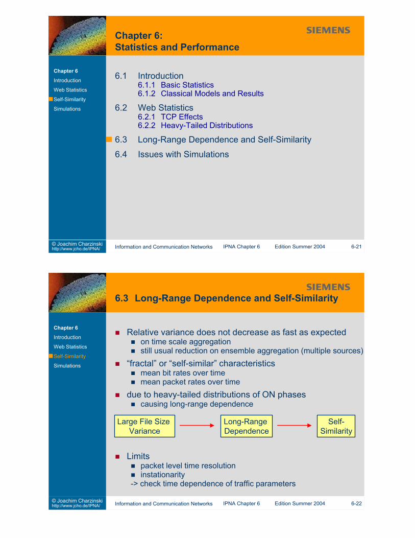
Variance-Time Analysisplot variance of aggregate versus aggregation timesimple, easy to understandalso gives second (variance) parameterslightly unreliable
R/S Analysisclassical approach for unknown mean and varianceplot rescaled adjusted range versus interval length
Periodogram Analysisshows increase of spectral density around zero
Abry-Veitch Estimatorusing wavelet theoryindependent of stationaritydetermines H and variance parameter from regression ofWavelet coefficients
6.4 Issues with SimulationsSteady State and Confidence
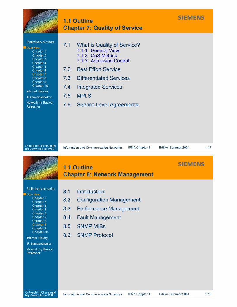
Effects of long-range dependent traffic
steady state reached slowlystochastic generators (input processes!)observed system state (e.g. queue length)
High variability at steady statehigh probability of “swamping” sample
Standard deviation of batch means decreases slowlyTo reduce batch means standard deviation by a factor of 10:simulate factor of 101/(1-H) longerH=0.5: factor 100 longerH=0.9: factor 10 000 000 000 longer!
... can never be simulated M/G/1 has infinite expected waiting time if the “G“ has infinitevariance
Mean Waiting Time
Residual Lifetime
model carefullyconsider packets instead of bursts orfor TCP, use M/G/r-PS or M/D/1-PS instead of M/G/1
limit distributionscheck validity of assumption(e.g. do simulation results change with limit?)introduce corresponding mechanisms into networks(e.g. limit on e-mail sizes)
6.1 How can you guarantee a limited queueing delay in a router?At what cost?
6.2 Find out the expectation and variance of the distributionsgiven on slide 6-9
6.3 Assume you did a simulation of traffic with Hurst parameterH=0.8 that took 10 seconds. How long does a simulation withconfidence intervals reduced to one tenth take?
This slide set is distributed to support students of the University of Stuttgart who attend the IPNA lectureduring summer term 2004. All other use requires written permission by Joachim Charzinski.
1. Introduction2. Network Layer (et al.)3. Transport Layer4. Applications and Application Layer Protocols5. Network Architectures6. Statistics and Performance7. Quality of Service8. Network Management9. Security
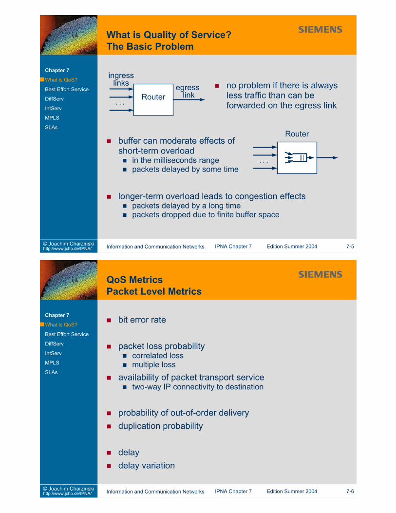
Availabilityreliability (Can I reach the server?)blocking probability (Am I allowed to use the service now?)in-service failures (Does the service break down after I gotstarted?)
achievable bit ratereaction time to user input
e.g. telephony connection set-up or Web page retrievalcan consist of many packet transfer times + repetitions in caseof losses
audio / video qualityachievable quality for a certain codec (time and spaceresolution, noise)impact of packet level effects on quality
lost packetsdelayed packets (often equivalent to loss but impact onsynchronization)
Aim:Once a user has been admitted to a service, they should havea chance to finish their task.
Avoid:interruption of audio/video communicationsinterruption of long file transfers(repeated transfer wastes resources)
Mechanism:Admit only the amount of traffic a network can handle.Block the rest of the traffic.
Problems:blocking also reduces perceived quality→ AC does not help on insufficiently dimensioned networksresource requirements are hard to describe (e.g. for elastictraffic)all concerned network links need to take part in the admissiondecision
processing and communication overheadcomplexity of network nodes
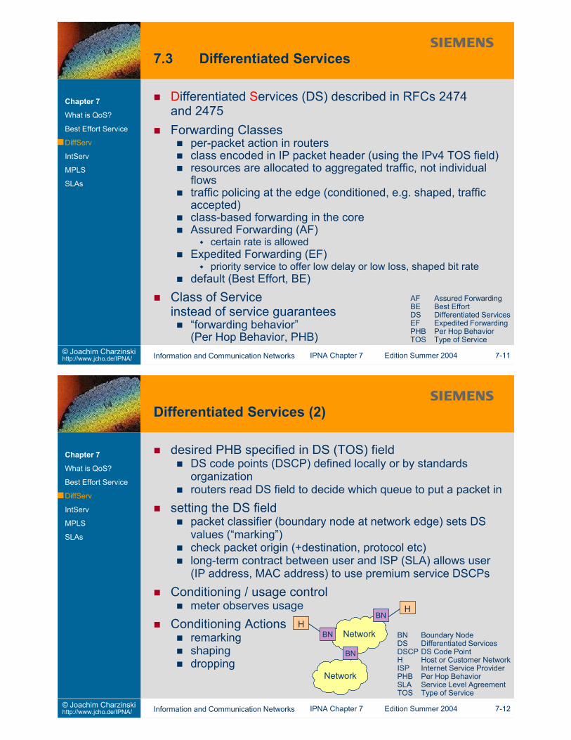
Differentiated Services (DS) described in RFCs 2474and 2475Forwarding Classes
per-packet action in routersclass encoded in IP packet header (using the IPv4 TOS field)resources are allocated to aggregated traffic, not individualflowstraffic policing at the edge (conditioned, e.g. shaped, trafficaccepted)class-based forwarding in the coreAssured Forwarding (AF)
certain rate is allowedExpedited Forwarding (EF)
priority service to offer low delay or low loss, shaped bit ratedefault (Best Effort, BE)
Class of Serviceinstead of service guarantees
“forwarding behavior”(Per Hop Behavior, PHB)
Chapter 7
What is QoS?
Best Effort Service
DiffServ
IntServ
MPLS
SLAs
AF Assured ForwardingBE Best EffortDS Differentiated ServicesEF Expedited ForwardingPHB Per Hop BehaviorTOS Type of Service
desired PHB specified in DS (TOS) fieldDS code points (DSCP) defined locally or by standardsorganizationrouters read DS field to decide which queue to put a packet in
setting the DS fieldpacket classifier (boundary node at network edge) sets DSvalues (“marking”)check packet origin (+destination, protocol etc)long-term contract between user and ISP (SLA) allows user(IP address, MAC address) to use premium service DSCPs
Conditioning / usage controlmeter observes usage
Conditioning Actionsremarkingshapingdropping
Network BN Boundary NodeDS Differentiated ServicesDSCP DS Code PointH Host or Customer NetworkISP Internet Service ProviderPHB Per Hop BehaviorSLA Service Level AgreementTOS Type of Service
Resource reservation protocol (RSVP) described inRFC2205
IP protocol ID 46 (raw IP packets), optional transmission onUDProuter alert option [RFC 2113] set
PATH message from origin to destinationeach router stores a “path state” per flow,including the previous hop
RESV message from dest. to originuses recorded previous hopto follow the path back
Soft State principleperiodic repetition of PATH and RESV messages
unidirectional operationcompliant with existing IP routingreverse data can take another path in the networkseparate signalling required for reverse data path
Policy Decision Points (PDP) in the networkrequired for globally (at least network-wide) coordinated policiesknow who is allowed to do whateach router can ask a PDP if the global policy allows a specificclient request to be granted
COPS data format is compatible to RSVPsimplifys routers’ actions
Problem:Protocol is well specifieddata structure semantics are not
LSPs can have allocated bandwidthflexible way to optimize or reroute traffic flows in a network
Label switching can overcome standard IP routing limitationsclassical IP routing cannot fully distribute trafficRSVP allows full optimization of routing for a given traffic matrixon a network topology
R4 N3
R2
R3
R1
N1
N2
classically, all traffic from N1 and N2
to N3 would have to take the same
route between R1 and R4
classically, all traffic from N1 and N2
to N3 would have to take the same
route between R1 and R4
Different routes can be allocated for different QoS classes
IP shortest path routing is determined bylink / interface cost metricsby changing those metrics, routing can be changedlink loads can be reduced by appropriate routing
Example (simplified):
R2R1
Chapter 7
What is QoS?
Best Effort Service
DiffServ
IntServ
MPLS
SLAsR5R4R3
N1 N2
N3
hop count basedrouting metrics
flows from N1 to N2 and N1 to N3 all go via the link R1-R2
1
1 1
11
changed metricsflows from N1 to N2 and N1 to N3 take different paths
Traffic Engineering without MPLSOptimization of Routing Metrics
link loads can be reduced by appropriate routinghighly non-linear influence of metrics on link loads
hard to find out metrics for optimum load distributionnot every target routing can be realized with metricslinear solution mechanisms not applicable
metrics can be optimized using heuristic approachesgreedy search
always increase metric value of the link with highest loadgenetic algorithms
vector contains all link cost metrics of the networkpopulation of several such vectors is a generationsubsequent generation created through copy, crossover, mutationcontrolled by “fitness” indicated by e.g. highest link load
simulated annealingrandom movement in 2n-dimensional discrete parameter space(for a network with n links)
7.1 Find out the availability of your favourite Web server. How often(out of 50 experiments) do you get the entry page withinreasonable time? How often do you get no answer at all?
7.2 Have a look at some major ISPs’ Web sites and check the SLAsthey offer their customers.
7.3 Can different QoS classes be introduced with “flat rate” pricing?
7.4 What is the difference between in-band and out-of-band networkmanagement? What are the advantages / disadvantages?
7.5 What is the difference between authentification andauthorization?
7.6 Are there other ways than encryption to achieve confidentialcommunication?
7.7 What is the format of an IPv6 packet header? What fields havebeen added / left out / moved to options compared to an IPv4header?
This slide set is distributed to support students of the University of Stuttgart who attend the IPNA lectureduring summer term 2004. All other use requires written permission by Joachim Charzinski.
1. Introduction2. Network Layer (et al.)3. Transport Layer4. Applications and Application Layer Protocols5. Network Architectures6. Statistics and Performance7. Quality of Service8. Network Management9. Security
“Simple” Network Management Protocol (SNMP)specification of data structures (MIB Management InformationBase)specification of transfer encodingspecification of a communication protocol
... has problems in dynamic (chaotic) environmentsas found in many small to medium size enterprise networks
... should help tracking down errorserrors can be introduced by configuration changeshave the current configuration available when locating othererrors
Configuration tracking needs to be done continuouslyarchive results
Objective:Prevent load or configuration related performance problems
Performance problems may be perceived as “failures” by users!“hard” problems (equipment failure) may manifest themselvesas performance problems due to automatic reconfiguration
Approach: Monitoring of network performanceperiodic evaluation of resultsnetwork-wide observationsautomatic baselining
Also useful for end-user interfacenetwork manager knows problems before phone calls come inusers can get (good) performance statistics fromInternet/Intranet server
Problem: deduce the true failure cause from (indirect)indications
indications are observed (e.g.: highly variable delay)
condensation of raw data into informationeach single data item has little informationcombinatorial or temporal correlation of data
prevent event stormssingle fault can cause many measures to trigger alarmsde-duplication of multiple events by network managementsoftwareDo not overload human operators by too much (identical)information!
see RFC 1213, RFC 1907 and many othersHierarchical structure of informationunique identification of information fields (for all vendors andnations)standard SNMP MIBs defined for many network elementtypes
allow retrieving information without knowledge of machinedetailsget-next mechanism for retrieving “all information”without prior knowledge of what will be available
element values encoded in ASN.1Abstract Syntax Notationdefines content transfer encodingreceiver can detect data type and encoding
similar to TLV (Type, Length, Value) principleType specifies a data typelength gives total length of fieldSEQUENCE type allows hierarchical specification
uses UDP (port 161; port 162 for traps)SNMP Version 3 features
message authentication (who sent the message?)privacy (avoid unauthorized reading)authorization and view-based access control(who can change what?)remote configuration of security system
Communication beweenManagement Application andNetwork Element
read configurationread counters / statisticsmodify configurationnotify management station of eventconfigure security
Trapsused for spontaneous communication from agent to serverserver address is pre-configured in agentserver is prepared to receive Trap messages from (many)agents
This slide set is distributed to support students of the University of Stuttgart who attend the IPNA lectureduring summer term 2004. All other use requires written permission by Joachim Charzinski.
1. Introduction2. Network Layer (et al.)3. Transport Layer4. Applications and Application Layer Protocols5. Network Architectures6. Statistics and Performance7. Quality of Service8. Network Management9. Security
use keys to encrypt and decrypt a plain text message P
Symmetric key methods (“Private Key” methods)fast operation, suitable for mass data encryptionone key needed for any pair of communication partnersrisk of key being revealed
Asymmetric key methods (“Public Key” methods)generate pairs of keys where one cannot (easily)be computed from the otheruse public key and secret keyTrust Center gives access to all public keys
Hybrid methodgenerate random key for symmetric encryptionuse public key method to transfer symmetric keyfollowing communication encrypted using symmetric key (moreefficient)
hide texts e.g. in large inconspicious audio or video filesset the least significant bits of some pixels or audio samplesaccording to the information to be hiddennot as efficient as encryption
not as obvious as encryptionhard to find in a data streamhard to track even where encryption is illegal
also used for digital signatures for copyrightdigital “watermark”
Authentication Header (AH)to detect manipulation“signature” of header and payload (hash function)
Internet Key Exchange (IKE) [RFC2409]ISAKMP: Internet Security Association and Key ManagementProtocol [RFC2408]
AuthenticationKey ManagementSecurity Associations
“Oakley” for key exchange, using the Diffie-Hellman principle:
f(x) = ax (mod p) “one-way” function (logarithm is hard to compute)parameters a and p are known by all usersuser i has private key Xipublic key is Yi = aXi (mod p)for communication between i and j use Zij = Zji = (Yj)Xi = aXiXj mod puse Zij for encryption and decryption (symmetric key)
Secure a whole enterprise networkCommon point of trust
reduces effort in securing many computersreduces risk of a misconfigured computer compromising others’securityonly one system to verify and observeonly few services need to go across
GlobalInternet
(insecure)
Intranet(protected)
FirewallFirewall
selected servicescan pass throughselected servicescan pass through
as simple as possibleeasy to implementeasy to understand implementation
as little functionality as possible (per module)as little trust as possible (between modules)
no trust in unprotected modulesno trust in any WAN userconsider attacks from both sidesonly provide minimum servicesblock the restprotect firewall configuration
Packet Filteringrules specify what to do with a packeton the basis of IP addresses (local and remote) and / or portnumbersblock access to unwanted servers and services
locally compiled lists or lists from service providersactions: pass through / translate network address / translateport / drop
Application Gatewayrestriction to basic functionality of application level protocolsproxy server
Most, if not all methods have a residual error probabilitycan be made arbitrarily small, but never zero
Simple Exampleschance of guessing a parity bit right is 0.5good chance of manipulating an original text to fit a given 10 bitdigital signature
“brute force” attacks are always possibleattacks that use little or no knowledge of the securitymechanismssimply rely on probabilitye.g. (parallel and distributed) cracking of encryption keys
try every possible keyuntil you can decrypt the messagetry every possible password until you findone that matches the encrypted text Perfect security in
This slide set is distributed to support students of the University of Stuttgart who attend the IPNA lectureduring summer term 2004. All other use requires written permission by Joachim Charzinski.
1. Introduction2. Network Layer (et al.)3. Transport Layer4. Applications and Application Layer Protocols5. Network Architectures6. Statistics and Performance7. Quality of Service8. Network Management9. Security
IP version 6 is the designated successor of IPv4(see Chapter 2)
also known as IPnG (next Generation)version 5 was assigned for the (experimental)Stream Protocol (ST)described in RFCs 1883, 2460, 2462–2464, 2373–2375, 2526
Motivation for IPv6increased address space to allow maintainingend to end transparencyIntroduction of Quality of Service mechanismson Network LayerImprovement of Network Layer Security (end to end)
completely new header formatlarger addressesnew options and option handling32bit alignment for faster processing
can also bedone with IPv4can also bedone with IPv4
Reasons for introducing IPv6address space problem solved
especially interesting for mobile networks and large growthcountries (China)
support of flow labelsfull support for tunnelling and interworking
v6 over v4 networksv4 over v6 network not defined yet (not yet needed)
MPLS Multiprotocol Label Switching
Chapter 10
Introduction
Addressing
IP Packet Header
Autoconfiguration
Security Support
Changes to others
Migration Strategies
Reasons for not introducing IPv6changes required to all routers and end systemschanges required to some applicationsIPv4 works wellenormous overhead due to long addresses(especially for short packets)addressing problem not as urgent as believed 5 years agolabel stacking not supported→ flow label field not useful for MPLS
128 bit (16 octets) addresses [RFC1887]more than 1024 addresses per m2 of earth surfaceenough freedom for structured addressing
Address Typesunicast addresses [RFC2374]
global aggregatable / link local / site localanycast addresses
deliver packet to one of a set of addresses that has the shortestpath
multicast addressestextual representation
8x16bit integers, represented by 4 hex digitse.g. 1080:0000:0000:0000:00AB:0801:200E:3AB2short form: 1080:0:0:0:AB:0801:200E:3AB2“::” used to denote as many “0” fields as necessary (once perstring), e.g.1080::AB:0801:200E:3AB2prefix indication in decimal,e.g. 1090:2ADC:3300:: /40 for a 40 bit prefix
P (format prefix 001 for aggregatable global unicast addresses)TLA ID: Top Level Aggregation
Transport Provider, e.g. an ISP with global networkres.: reserved for future use (all zeroes)NLA ID: Next Level Aggregation (e.g. an ISP)SLA ID: Site Level Aggregation (e.g. like an IPv4 subnetwork)Interface Identifier
e.g. random number (privacy extension [RFC3041]e.g. encoding of lower layer hardware address(with some bits in between) or EUI64 addressesARP replaced by Neighbor Discovery for IPv6
ARP Address Resolution ProtocolEUI End User InterfaceICMP Internet Control Message ProtocolID IdentifierISP Internet Service Provider
IPv4 fields removed from IPv6 headersHeader lengthIdentificationHeader Checksum
IPv4 fields changed for IPv6 headersPrecedence and Type of Service → Traffic Class(DiffServ Code Point)Total length → Payload LengthTime to live → Hop LimitProtocol → Next Header
Extension Headerse.g. for Fragmentation(replaces Flags & Fragment Offset fields)use “next header” field
first 2 bits of Type determine handling of unknown options:00=skip, 01=discard packet,10=discard packet and send ICMP message,11=like 10 but only if destination address was not multicast
option field contains extra 4 Bytes length indicatormaximum length of packet increased to 4GB
not to be used in conjunction with fragmentation
Changes necessary to TCP and UDP [RFC2147]UDP length=0 indicates “use IPv6 length value”TCP MSS=65535 indicates infinite MSSTCP URG pointer can only address data up to octet 65535
especially interesting for high-speed reliable local networksreduce processor interrupt load at end systems
IPv6 routers do not fragment packetsPath MTU discovery is mandatory
if path MTU discovery is not possible, send packets for smallMTU sizeif absolutely necessary, fragment at source (“end-to-endfragmentation”)re-discovery may be necessary after path change
source and destination nodes can do fragmentation andreassembly
to transmit larger size payloadsfragment offset / identification principle similar to IPv4
use Fragment Header to indicatenext headerfragment offset“more fragments” (1 bit)identification MTU Maximum Transmission Unit
Traffic Class / DiffServ Code Pointnot counted in check sum or authentification information
routers can change the Traffic Class value without recomputingchecksums
Flow Labelsimplifies special treatment for flowsflow identified by source IPv6 address and flow labelrandom uniform choice of flow labels optimizes hashing inroutersexact function still to be defined
defined by destination address and Security Parameter Index(SPI)Key for authentification / encryptionAlgorithms for authentification / encryptionKey lifetimeSecurity association lifetimeSource addressSecurity level (confidential, unclassified, etc)
Key ManagementInternet Key Exchange (IKE) [RFC2409]Internet Security Association and Key Management Protocol(ISAKMP) [RFC2408]
Migration StrategiesTunnelling of IPv6 over IPv4 networks
encapsulation of IPv6 packet in IPv4 packettransmission over IPv4 network as far as neededingress router of IPv6 network strips off IPv4 header (end oftunnel)configured tunnels [RFC1933]
use next IPv4/IPv6 router as end of tunnelautomatic tunnels [RFC1933]
using IPv4 compatible addressesIPv4 address can be deduced from IPv6 addressnewer developments: “6over4” [RFC2529], “6to4” [Internetdrafts]
exchange of routing and reachability information betweenIPv6 islandsensure consistency between IPv4 and IPv6 routing
Header Translation (SIIT) [RFC2765]translation between IPv4 and IPv6 headerstranslation between ICMPv4 and ICMPv6 packetstranslation of fragment extension header into IPv4 fragment infotemporary allocation of IPv4 address for IPv6 host(e.g. via DHCP)no multicast support
NAT-PT: Protocol Translation [RFC2766]NNAT or DSTM
temporary allocation of IPv4 address for an IPv6 host(e.g. via DHCP)NNAT server causes reconfiguration of IPv6 hostafter IPv4 DNS query
Application Level GatewaysFirewalls, Proxiesstatically configured addresses on IPv4 / IPv6 sidesallow an institution to run IPv6 internally and communicateexternally via IPv4 (or vice versa)