31
| Date post: | 19-Dec-2015 |
| Category: |
Documents |
| View: | 222 times |
| Download: | 0 times |


OUTLINEOUTLINE
• OverviewOverview
• InstrumentsInstruments
• Scientific ObjectivesScientific Objectives

• Prepared by ASI with the participants INFN&IASF.Prepared by ASI with the participants INFN&IASF.• Sensitive in the range 30 Mev-50 Gev & 15-45keV. Sensitive in the range 30 Mev-50 Gev & 15-45keV. • Having a large FOV covering Having a large FOV covering 1/5 of the entire sky at 1/5 of the entire sky at
energies above 30Mev.(energies above 30Mev.(3 sr)3 sr)• Based on the state-of-the-art technology of solid state Based on the state-of-the-art technology of solid state
Silicon detectors and associated electronics Silicon detectors and associated electronics developed in Italian Lab. developed in Italian Lab.
120kg (the total satellite mass is 120kg (the total satellite mass is 350kg)350kg)• Primary scientific goals include the study of ;Primary scientific goals include the study of ;
-AGN-AGN-GRBs-GRBs-Galactic sources-Galactic sources-Unidentified Gamma-ray sources-Unidentified Gamma-ray sources-Diffuse Gamma-ray emission-Diffuse Gamma-ray emission-High-precision timing studies-High-precision timing studies-Quantum Gravity testing-Quantum Gravity testing
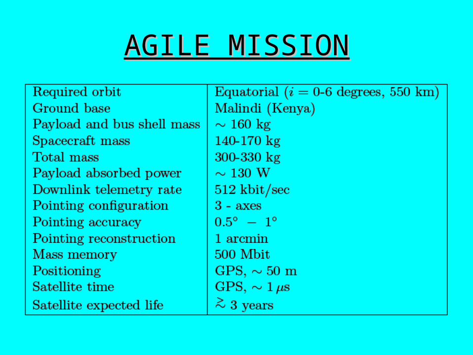
AGILE AGILE MISSIONMISSION

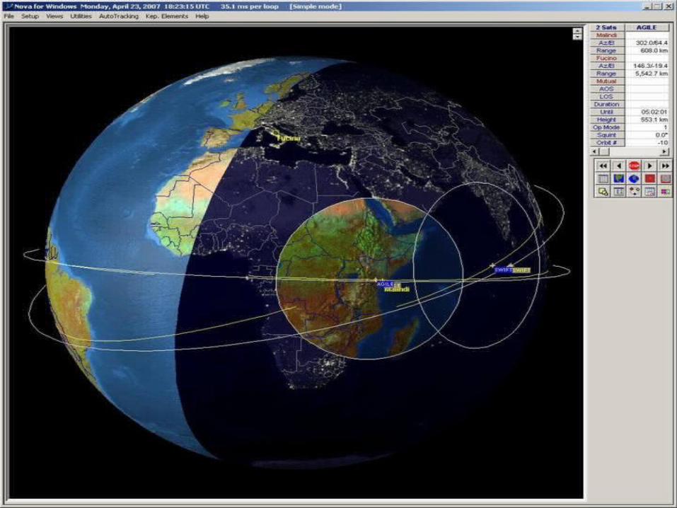
AGILE was succesfully AGILE was succesfully launched on April 23, launched on April 23, 2007 at 10:00 GMT in an 2007 at 10:00 GMT in an equatorial orbit with an equatorial orbit with an altitude of 550 km and altitude of 550 km and inclination of inclination of 0-6 0-6 deg.by the Indian PSLV deg.by the Indian PSLV rocket from the rocket from the Shriarikota ISRO base Shriarikota ISRO base (Chennai-Madras), India. (Chennai-Madras), India.
• AGILE Launch• PSLV-C6
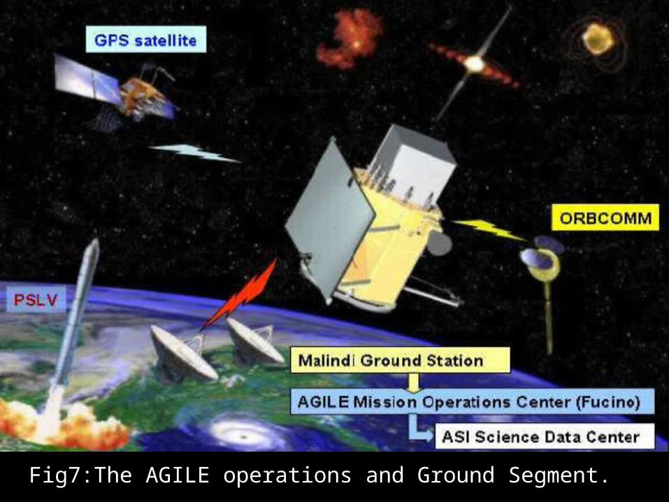
Fig7:The AGILE operations and Ground SegmentFig7:The AGILE operations and Ground Segment.
AGILE MISSIONAGILE MISSION

INSTRUMENTSINSTRUMENTS
Fig1:LEFT:The AGILE integrated satellite in its final configuration.Fig1:LEFT:The AGILE integrated satellite in its final configuration.
RIGHT:Hard X-ray imager,the gamma-ray Tracker, and the RIGHT:Hard X-ray imager,the gamma-ray Tracker, and the Calorimeter. Calorimeter.


TheThe AGILEAGILE payload is made of three detectors combined into payload is made of three detectors combined into one integrated instrument with broad-band detection and one integrated instrument with broad-band detection and imaging capabilities.imaging capabilities. The AnticoincidenceThe Anticoincidence and and Data Data Handling systemsHandling systems complete instrument.complete instrument.
1.The Gama-Ray Imaging Detector 1.The Gama-Ray Imaging Detector ((GRIDGRID))
2.The Hard X-ray Imager 2.The Hard X-ray Imager ((Super-AGILESuper-AGILE))
3.The Mini-Calorimeter 3.The Mini-Calorimeter ((MCMC))

1.1. The Gamma-Ray Imagıng DetectorThe Gamma-Ray Imagıng Detector
GRIDGRID • Sensitive in the rangeSensitive in the range
30Mev-50Gev30Mev-50Gev• Consisting of ;Consisting of ;
- A Silicon-Tungsten Tracker- A Silicon-Tungsten Tracker
- A Cesium Iodide - A Cesium Iodide CalorimeterCalorimeter
- The Anticoincidence System- The Anticoincidence System• Characterised by the Characterised by the
smallest ever obtainedsmallest ever obtained deadtimedeadtime ≲≲ 220000μμss
• Source location accuracySource location accuracy 1515´́
• FOVFOV 2.5 sr2.5 sr
Fig2:Engineering model of the Fig2:Engineering model of the AGILE instrument. The GRID is AGILE instrument. The GRID is made of 12 silicon-tungsten planes made of 12 silicon-tungsten planes and the Mini Calorimeter positioned and the Mini Calorimeter positioned at the bottom of the instrument.at the bottom of the instrument.

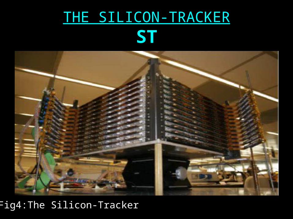
THE SILICON-TRACKERTHE SILICON-TRACKER
STST
Fig4:The Silicon-TrackerFig4:The Silicon-Tracker

• Providing the Providing the γγ-ray imager is based on photon -ray imager is based on photon conversion into electron-positron pairs.conversion into electron-positron pairs.
• Consisting of a total of 12 trays…Consisting of a total of 12 trays…
• The fundamental Silicon detector unit is a tile of area The fundamental Silicon detector unit is a tile of area 9.5x9.5 cm9.5x9.5 cm22 ,microstrip pitch equal to ,microstrip pitch equal to 121 121 μμmm,and ,and thickness thickness 410 410 μμmm(Fig5).(Fig5).
• The adopted ‘floating readout strip ’ system has a total of The adopted ‘floating readout strip ’ system has a total of 384 readout channels and three readout 384 readout channels and three readout TAA1TAA1 chips per chips per Si-tile.Si-tile.

Fig5:Schematic layout of the fundamental 9.5x9.5 cmFig5:Schematic layout of the fundamental 9.5x9.5 cm2 2
unit(tile) of the AGILE Sİ-Tracker.unit(tile) of the AGILE Sİ-Tracker.
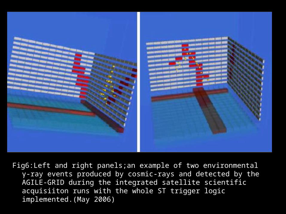
Fig6:Left and right panels;an example of two environmental Fig6:Left and right panels;an example of two environmental γγ-ray -ray events produced by cosmic-rays and detected by the AGILE-GRID events produced by cosmic-rays and detected by the AGILE-GRID during the integrated satellite scientific acquisiiton runs with the during the integrated satellite scientific acquisiiton runs with the whole ST trigger logic implemented.(May 2006)whole ST trigger logic implemented.(May 2006)

Fig6: (Tracking perf.)Schematic rep.and typical Fig6: (Tracking perf.)Schematic rep.and typical results of beamtests carried out at CERN. results of beamtests carried out at CERN. The right panel shows the results of the The right panel shows the results of the AGILE beamtest carried out in August,2000 at AGILE beamtest carried out in August,2000 at the CERN T11 beamline.(East Hall,CERN the CERN T11 beamline.(East Hall,CERN PS)PS)

MINI CALORIMETERMINI CALORIMETER
MCMC• Operating in the ‘burst’ mode is the 3rd AGILE detector.Operating in the ‘burst’ mode is the 3rd AGILE detector.• The energy range for this non-imaging detector is The energy range for this non-imaging detector is
25keV-200MeV.25keV-200MeV.• Made of 30 Thallium activated Cesium Iodide (CsI(Tl)) Made of 30 Thallium activated Cesium Iodide (CsI(Tl))
bars arranged in two planes,for a total radiation length bars arranged in two planes,for a total radiation length 1.5 X1.5 X 0. 0. The signal from each CsI bar is collected by two The signal from each CsI bar is collected by two photodiodes placed at both ends.photodiodes placed at both ends.
• deadtime deadtime 5 5 μμss • The main goals are ;The main goals are ;
– obtaining additional information on the energy obtaining additional information on the energy deposited in the CsI bars….deposited in the CsI bars….
– detecting GRBs and other impulsive events with detecting GRBs and other impulsive events with spectral and intensity information in the range spectral and intensity information in the range ~~0.3-0.3-100MeV100MeV
THE ANTICOINCIDENCE SYSTEM THE ANTICOINCIDENCE SYSTEM
ACAC• Aimed at both charged particle background rejection and Aimed at both charged particle background rejection and
preliminary direction reconstruction for triggered preliminary direction reconstruction for triggered photons.photons.
• Completely surrounding with AGILE detectors.Completely surrounding with AGILE detectors.
• Each lateral face segmented in three plastic scintillator Each lateral face segmented in three plastic scintillator layers connected with photomultipliers placed at the layers connected with photomultipliers placed at the bottom.bottom.

The operating principle of GRID is based onThe operating principle of GRID is based on ;;
the conversion of the conversion of γγ-ray photons in -ray photons in
electron-positron pairs by thin tungsten electron-positron pairs by thin tungsten
sheets and tracking the pairs, in sheets and tracking the pairs, in
energy and directions, by microstrip energy and directions, by microstrip
silicon detectors,thus reconstructing silicon detectors,thus reconstructing
the kinematic of the impingingthe kinematic of the impinging
photonphoton (Feroci,M. et al.2007)(Feroci,M. et al.2007)

2. 2. The Hard X-Ray ImagerThe Hard X-Ray Imager
Super-AGILESuper-AGILE
Fig7:Super-AGILEFig7:Super-AGILE
2. 2. The Hard X-Ray ImagerThe Hard X-Ray Imager
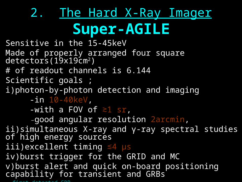
Super-AGILESuper-AGILE• Sensitive in the 15-45keVSensitive in the 15-45keV• Made of properly arranged four square detectors(19x19cmMade of properly arranged four square detectors(19x19cm22))• # of readout channels is 6.144# of readout channels is 6.144• Scientific goals ;Scientific goals ;
i)photon-by-photon detection and imaging i)photon-by-photon detection and imaging -in-in 10-40keV10-40keV,,-with a FOV of-with a FOV of ≳≳1 1 srsr,,--good angular resolutiongood angular resolution 2arcmin2arcmin,,
ii)simultaneous X-ray and ii)simultaneous X-ray and γγ-ray spectral studies of high energy -ray spectral studies of high energy sourcessourcesiii)excellent timingiii)excellent timing 4 ≲4 ≲ μμssiv)burst trigger for the GRID and MCiv)burst trigger for the GRID and MCv)burst alert and quick on-board positioning capability for v)burst alert and quick on-board positioning capability for transient and GRBstransient and GRBs
first detected GRB...

AGILE’s SCIENTIFIC OBJECTIVESAGILE’s SCIENTIFIC OBJECTIVES
• AGNAGN-wide FOV survey.-wide FOV survey.-quick reaction to transients.-quick reaction to transients.-SA monitoring in the hard X-ray band.-SA monitoring in the hard X-ray band.
-correlative obs. in the radio,optical,X-ray,TeV-correlative obs. in the radio,optical,X-ray,TeV
• GRBGRB-expected detection rate above 50 MeV:5-10 event/year-expected detection rate above 50 MeV:5-10 event/year-broad-band spectral information-broad-band spectral information-SA imaging(-SA imaging(~~1’-2’ for intense GRBs)1’-2’ for intense GRBs)-search for sub-milisecond GRB pulses-search for sub-milisecond GRB pulses

• PULSARSPULSARS-high-resolution timing of known -high-resolution timing of known γγ-ray pulsars,-ray pulsars,-period searches for Galactic unidentified sources,-period searches for Galactic unidentified sources,-milisecond pulsars.-milisecond pulsars.
• UNIDENTIFIED SOURCESUNIDENTIFIED SOURCES-deep exposure,variability studies,-deep exposure,variability studies,-refined positions,search for counterparts,-refined positions,search for counterparts,-serach for new transients and quicklook alert-serach for new transients and quicklook alert
• SUPERNOVA REMNANTSSUPERNOVA REMNANTS-search and precise imaging with deep exposures-search and precise imaging with deep exposures-monitoring of plerions in SNRs-monitoring of plerions in SNRs--γγ-ray /TeV studies-ray /TeV studies

• BINARY SYSTEMSBINARY SYSTEMS-neutron star binaries,-neutron star binaries,-black-hole systems;microquasars-black-hole systems;microquasars-interacting binaries,-interacting binaries,-SA monitoring and simultaneous detection.-SA monitoring and simultaneous detection.
• DIFFUSE EMISSIONDIFFUSE EMISSION-deep exposure and precise mapping mapping of Galactic -deep exposure and precise mapping mapping of Galactic emission,emission,-study of cosmic-ray origin and propagation-study of cosmic-ray origin and propagation
• GALAXIESGALAXIES-deep pointings at the SMC and LMC-deep pointings at the SMC and LMC-testing dark matter model(by deep exposures of -testing dark matter model(by deep exposures of Andromeda)Andromeda)-deep exposures of cluster of galaxies-deep exposures of cluster of galaxies

• SOLAR FLARESSOLAR FLARES
-Si-tracker ratemeter transient detection(-Si-tracker ratemeter transient detection(≳≳ 100keV),100keV),
-MC detection in the range 25keV-200MeV,-MC detection in the range 25keV-200MeV,
• FUNDAMENTAL PHYSICSFUNDAMENTAL PHYSICS
-quantum gravity tests for sub-ms GRB pulses,-quantum gravity tests for sub-ms GRB pulses,
-high-precision pulsar timing and QG effects,-high-precision pulsar timing and QG effects,
-MACHO emission from our and nearby galaxies.-MACHO emission from our and nearby galaxies.
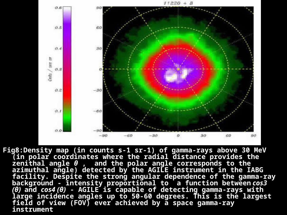
Fig8:Density map (in counts s-1 sr-1) of gamma-rays above 30 MeV (in Fig8:Density map (in counts s-1 sr-1) of gamma-rays above 30 MeV (in polar coordinates where the radial distance provides the zenithal polar coordinates where the radial distance provides the zenithal angle angle θθ , and the polar angle corresponds to the azimuthal angle) , and the polar angle corresponds to the azimuthal angle) detected by the AGILE instrument in the IABG facility. Despite the detected by the AGILE instrument in the IABG facility. Despite the strong angular dependence of the gamma-ray background - intensity strong angular dependence of the gamma-ray background - intensity proportional to a function betweenproportional to a function between cos3 (θ) cos3 (θ) and and cos4 (θ)cos4 (θ) - AGILE is - AGILE is capable of detecting gamma-rays with large incidence angles up to capable of detecting gamma-rays with large incidence angles up to 50-60 degrees. This is the largest field of view (FOV) ever achieved 50-60 degrees. This is the largest field of view (FOV) ever achieved by a space gamma-ray instrumentby a space gamma-ray instrument


REFERENCESREFERENCES
1.Science with AGILE,20041.Science with AGILE,2004
http://agile.asdc.asi.it/a-science-27.pdf
2. The AGILE mission and its scientific 2. The AGILE mission and its scientific
instruments ,Tavani,M. Et al, 2006SPIE.6266E.2Tinstruments ,Tavani,M. Et al, 2006SPIE.6266E.2T 3. Gamma-ray Astrophysics with the Space AGILE 3. Gamma-ray Astrophysics with the Space AGILE
Detector,Pittori,C.;Tavani,M.;the AGILE Detector,Pittori,C.;Tavani,M.;the AGILE
Team,2006ChJAS.6a.373PTeam,2006ChJAS.6a.373P 4.ASI Data Center4.ASI Data Center
http://agile.rm.iasf.cnr.it/

FINEFINE


