The Southern African Institute of Mining and Metallurgy Base Metals Conference 2013 T. Hirsi, P. Salonen, and J. Vaarno 65 Outotec ® cooling towers provide cooling efficiency and low emissions in gypsum removal in SX plants T. Hirsi, P. Salonen, and J. Vaarno Outotec (Finland) Oy With gypsum removal before solvent extraction (SX), the maintenance expenditure and downtime of SX plants can be considerably reduced and higher product quality achieved. Uncontrolled gypsum precipitation has been one of the major challenges in SX processes. Particularly after the high-temperature reactor leach, gypsum precipitation causes equipment failure and dramatic crud formation in the following SX processes. Outotec has developed a new cooling tower design that can be used as part of the gypsum removal circuit. By reducing the temperature of the pregnant leach solution (PLS) to below the solubility point, gypsum is precipitated prior to the SX process. After gypsum removal, the temperature of the solution is adjusted for the SX process needs. The Outotec® Solution Cooling Tower has been designed to operate in harsh conditions, such as the gypsum removal process. The development of the tower is based on computational flow dynamics (CFD) modelling to find the optimal structure and to estimate the cooling efficiency and behaviour of the tower. The major novelty of the design is the horizontal airflow, allowing optimal droplet separation in the demisters, resulting in cooling efficiency combined with optimized drift loss. In gypsum removal, scaling on the surfaces of the demisters and nozzles is unavoidable. Therefore, it is crucial that the design also allows easy and fast maintenance. This is achieved by utilizing a patented structure for the cooling tower, enabling the use of horizontal airflow demisters that can undergo maintenance during operation. Thus the downtime of the tower can be minimized and a higher utilization rate achieved. In 2012 Outotec commissioned the first gypsum removal cooling tower installation with the new tower design at the Chambishi plc SX plant in Chambishi, Zambia, together with the installation of spent electrolyte cooling towers at Grupo Mexico’s zinc plant, Industrial Minera México (IMMSA), in San Luis Potosi, Mexico. During commissioning on both sites the tower cooling efficiency was validated against CFD modelling, and the results were found to be in accordance with calculated cooling results in similar conditions. Also, the maintenance procedures fulfilled expectations. Keywords: Gypsum removal, cooling tower, drift loss, solvent extraction, crud prevention. Introduction Gypsum content in the feed solution to solvent extraction (SX) can cause additional maintenance expenses and equipment downtime, as well as lead to a lower standard end product from SX. If this is the case, it is advisable to use gypsum removal before the SX process. Outotec has developed a new forced-draught solution cooling tower design. The development of the tower began with the need to streamline the maintenance of the solution cooling tower, while improving cooling efficiency and reducing emissions. In the first phase of the development of the new tower design, extensive measurements were taken of cooling based on the conventional design. Measurements from old towers were used to develop and validate a computational fluid dynamics (CFD) model. Since the developed simulation model is not geometry-dependent, it could be used to develop the geometry for the new cooling tower. The model enables the behavior of gas inside the tower, cooling efficiency, droplet behavior, and the functioning of the tower in different weather conditions and different applications to be estimated. After the CFD research phase, structural development commenced, concentrating on the optimized maintenance of cooling towers. This resulted in a structure that enables online maintenance of the tower demisters with minimum downtime during operation. Preliminary maintenance tests were carried out during the start-up with local maintenance personnel. True online maintenance can be realized and fully utilized only after some time of operation, but will not be discussed in this paper. (Outotec, n.d; Hirsi et al., 2013)
Transcript
The Southern African Institute of Mining and Metallurgy Base Metals Conference 2013 T. Hirsi, P. Salonen, and J. Vaarno
65
Outotec® cooling towers provide cooling efficiency and low emissions in gypsum removal in SX plants
T. Hirsi, P. Salonen, and J. Vaarno Outotec (Finland) Oy
With gypsum removal before solvent extraction (SX), the maintenance expenditure and downtime of SX plants can be considerably reduced and higher product quality achieved. Uncontrolled gypsum precipitation has been one of the major challenges in SX processes. Particularly after the high-temperature reactor leach, gypsum precipitation causes equipment failure and dramatic crud formation in the following SX processes.
Outotec has developed a new cooling tower design that can be used as part of the gypsum removal circuit. By reducing the temperature of the pregnant leach solution (PLS) to below the solubility point, gypsum is precipitated prior to the SX process. After gypsum removal, the temperature of the solution is adjusted for the SX process needs.
The Outotec® Solution Cooling Tower has been designed to operate in harsh conditions, such as the gypsum removal process. The development of the tower is based on computational flow dynamics (CFD) modelling to find the optimal structure and to estimate the cooling efficiency and behaviour of the tower. The major novelty of the design is the horizontal airflow, allowing optimal droplet separation in the demisters, resulting in cooling efficiency combined with optimized drift loss.
In gypsum removal, scaling on the surfaces of the demisters and nozzles is unavoidable. Therefore, it is crucial that the design also allows easy and fast maintenance. This is achieved by utilizing a patented structure for the cooling tower, enabling the use of horizontal airflow demisters that can undergo maintenance during operation. Thus the downtime of the tower can be minimized and a higher utilization rate achieved.
In 2012 Outotec commissioned the first gypsum removal cooling tower installation with the new tower design at the Chambishi plc SX plant in Chambishi, Zambia, together with the installation of spent electrolyte cooling towers at Grupo Mexico’s zinc plant, Industrial Minera México (IMMSA), in San Luis Potosi, Mexico. During commissioning on both sites the tower cooling efficiency was validated against CFD modelling, and the results were found to be in accordance with calculated cooling results in similar conditions. Also, the maintenance procedures fulfilled expectations.
Gypsum content in the feed solution to solvent extraction (SX) can cause additional maintenance expenses and equipment downtime, as well as lead to a lower standard end product from SX. If this is the case, it is advisable to use gypsum removal before the SX process.
Outotec has developed a new forced-draught solution cooling tower design. The development of the tower began with the need to streamline the maintenance of the solution cooling tower, while improving cooling efficiency and reducing emissions. In the first phase of the development of the new tower design, extensive measurements were taken of cooling based on the conventional design. Measurements from old towers were used to develop and validate a computational fluid dynamics (CFD) model. Since the developed simulation model is not geometry-dependent, it could be used to develop the geometry for the new cooling tower. The model enables the behavior of gas inside the tower, cooling efficiency, droplet behavior, and the functioning of the tower in different weather conditions and different applications to be estimated. After the CFD research phase, structural development commenced, concentrating on the optimized maintenance of cooling towers. This resulted in a structure that enables online maintenance of the tower demisters with minimum downtime during operation. Preliminary maintenance tests were carried out during the start-up with local maintenance personnel. True online maintenance can be realized and fully utilized only after some time of operation, but will not be discussed in this paper. (Outotec, n.d; Hirsi et al., 2013)
Base Metals Conference 2013
66
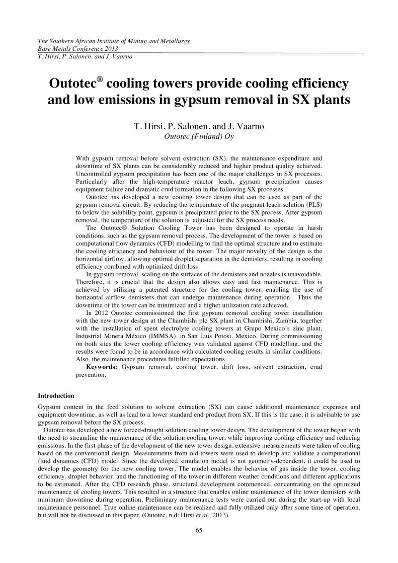
Outotec has currently (as of May 2013) supplied two installations of the new tower type for gypsum removal application: one of the installations is operational and the second is being installed. The currently operating installation (Figure 1) is a gypsum removal tower that is used to cool down slurry coming from leaching to copper solvent extraction, while the other installation is for gypsum removal ahead of zinc electrowinning. Outotec has also supplied cooling towers with the new design for spent electrolyte cooling.
Figure 1. Outotec® Solution Cooling Tower installation at Chambishi
Solution cooling towers are a distinctly different type of equipment than the counterflow induced-draught cooling towers used to cool water, which can be found in a wide range of industrial, residential, and other applications. Applications in which the solution cooling towers are used include, but are not limited to, spent electrolyte cooling, gypsum removal, and chloride removal, and solutions cooled in solution cooling towers contain sulphuric acid, solid particles, copper, cobalt, and/or zinc sulphate at high concentration causing scaling and other process problems inside the equipment. (Hirsi et al., 2013; Couper et al., 2009)
The quantity of droplets exiting the tower is called drift loss and represents the direct pollution produced by the cooling tower. In solution cooling towers these droplets can contain a range of environmentally harmful components, such as Cu, H2SO4, ZnSO4, and Cl. In addition to the emissions from the gas outlet, i.e. direct emissions, cooling towers produce indirect emissions, such as emissions caused by the production of the electricity needed to operate the equipment. In this article the non-direct emissions are not estimated or discussed.
New cooling tower design from Outotec
In a solution cooling tower, gas is introduced into the tower from the lower part of the tower and travels upwards, interacting with solution droplets that are falling down from the upper part of the tower. Some of the droplets are caught in the airflow travelling upwards through the tower, especially smaller droplets. As airflow exits the tower, it travels through the demisters. Usually there are two layers of demisters: a coarse demister and a fine demister to remove the droplets, i.e. minimize the drift loss.
Conventional solution cooling towers have vertical outflow demisters, i.e. the air exiting the tower is flowing upwards from the top of the cooling tower (Figure 2). Airflow is produced by a fan or fans placed at the lower part of the cooling tower blowing air horizontally inside the tower. The usual placement of the fan in conventional towers – at the side of the tower – requires the air to make a 90-degree turn when entering the tower. This usually leads to uneven air distribution inside the tower and the presence of dead spots, i.e. areas inside the tower where gas flow speed is
Outotec® cooling towers provide cooling efficiency and low emissions in gypsum removal in SX plants
67
negligible, especially with towers with a rectangular base design. This can also lead to uneven air distribution in the demisters and even to the return of exiting air into the tower.
The new Outotec cooling tower design (Figure 2) addresses the problems with airflow in traditional designs. The placement of the fan has been selected for a uniform gas flow pattern inside the cooling tower, with no sharp turns for the gas flow. Horizontal flow outlets achieve a more even gas flow with higher speeds through the demisters and out of the cooling tower. The new design offers advantages in cooling efficiency and droplet separation, and therefore also lower emissions and streamlined online maintenance. These topics are described in later sections.
Figure 2. Geometrical presentation of solution cooling towers, with a vertical outflow cooling tower (conventional design) on the left and a horizontal outflow tower (Outotec design) on the right. The arrows show the flow direction of the air (Hirsi et al., 2013)
The hot solution is dispersed as droplets countercurrently to the air entering the tower from the upper part of the
tower, usually just below the demister layers. Dispersion is achieved by gravity-operated plate dispensers or pressure nozzles. The use of plate dispensers leads to a larger droplet size. Lucas et al. (2013) found that the selection of the fluid dispersion system by itself can lead to a 40% increase in cooling tower performance. Similar differences have also been noticed in the CFD research carried out by Outotec. Since the cooling of the solution inside the tower is based on the evaporation of the solution and heat transfer between the droplets and cooling air inside the cooling tower, a relatively fine droplet size leads to a better cooling result. In the new Outotec cooling tower design, the direction of the sprays and its effect on cooling efficiency has been extensively tested (Hirsi et al., 2013; Couper et al., 2009; Outotec, n.d.).
Gypsum precipitation in process equipment
Gypsum causes scaling inside the cooling tower, process piping, and other process equipment. The most critical parts of the cooling tower regarding gypsum scaling are the demisters, spray nozzles, and outflow nozzles. Scaling in demisters hinders the airflow through the tower, which hinders cooling efficiency; scaling in the nozzles disturbs the spray pattern and diminishes the flow through the nozzles; and if the outflow nozzles are blocked, the tower has to be taken off-line for cleaning. With the innovative cleaning procedures employed with the Outotec® cooling tower, the uptime is increased with more efficient maintenance solutions that allow quicker cleaning and online cleaning of the demisters without using any cooling capacity.
In the Outotec® cooling tower, an internal curtain is used to prevent internal wall scaling. The curtain is made of a material that resists scaling, and is moved by the airflow inside the tower, so any large scaling is detached by the airflow from the curtain. Based on our experience of using this new curtain design for 6 months (as of March 2013), there is negligible scaling present in the curtain whenever the tower is stopped. The advantage of the curtain compared to materials attached straight to the wall is the possibility of changing the curtain if required and the additional cleaning benefit achieved through the movement.
Base Metals Conference 2013
68
Gypsum solubility in acidic solutions
Gypsum is white in pure form; usually the colour of the gypsum varies according to the metal components in the solution. Gypsum is formed from calcium, sulphuric acid, and water (CaSO4 * 2H2O). In acidic solutions, if the temperature rises above 90°C, the gypsum tends not to form if the solution becomes oversaturated. Instead of gypsum, anhydrate (CaSO4) is formed. Gypsum has many uses in construction, and it is also used as a fertilizer and soil conditioner. However, gypsum recovered from hydrometallurgical processes is usually not clean enough to be used in these applications. Gypsum produced by hydrometallurgical processes can contain precipitated components and is usually stored in waste areas.
Calcium is soluble in acidic solutions and is present as CaSO4. The solubility of calcium is dependent on the temperature of the solution, with solubility increasing with increasing temperature. In water, CaSO4 solubility increases slightly with rising temperatures and reaches its maximum at approximately 50°C, then starts to decrease. As H2SO4 is present in the solution, the solubility of calcium sulphate increases, but after a certain point it starts to diminish. Other solution parameters affecting the solubility of CaSO4 are the concentration of certain metal ions in the solution, such as Zn and Fe. Figure 3 shows the solubility of gypsum in an acidic solution; the data is based on an article by Dutrizac.
Figure 3. Saturation solubility of CaSO4 with varying H2SO4 concentrations and an increasing solution temperature (after Dutrizac, 2002)
Gypsum precipitation in SX – effects on the process and OPEX
Gypsum causes several kinds of problems in the SX process. For example, a calcium-saturated pregnant leach solution (PLS) can increase crud formation and precipitate on the cooler surfaces of the equipment, and cause scaling on picket fences and agitators.
Crud formation is a problem in all, or at least most, SX plants. Crud is a stable emulsion containing an organic and an aqueous solution and solid particles. The type and cause of crud differs between the operation plants. Crud can cause solvent losses and directly affects operating costs (Ritcey and Ashbrook, 2006). Fine gypsum particles increase crud formation, and problems occur especially when crud accumulates on the picket fences in the settler. Gypsum scaling can result in poor phase separation and stable emulsions. The settler capacity and throughput can be reduced (Ritcey, 2002). Figure 4 shows the crud layer in an organic solution at a nickel production plant caused by gypsum precipitation in the process.
Outotec® cooling towers provide cooling efficiency and low emissions in gypsum removal in SX plants
69
Figure 4. Crud caused by gypsum in a solvent extraction settler
Problems can also occur when calcium is extracted in high amounts into the organic phase and it precipitates after
returning to aqueous phase in the scrubbing and stripping stages (Nofal et al., 2001). This problem cannot be avoided completely with some extractants, like Versatic 10 and D2EHPA, but minimizing the calcium in the PLS will decrease the operational costs of the SX process.
A calcium-saturated solution causes gypsum scaling on the surfaces of equipment. Gypsum on the agitators directly increases power consumption. Gypsum precipitate can force a plant to shut down for maintenance and gypsum removal. An example of massive gypsum precipitation inside an SX settler is shown in Figure 5. The plant was operated with a > 1 m thick gypsum layer prior to the maintenance shutdown.
Figure 5. Gypsum cleaning during maintenance shutdown in a copper SX plant settler
Production lost can be estimated based on excess maintenance shutdown days. Indicative figures of production loss
* London Metal Exchange, 24 Apr.2013 In the Chambishi plc SX plant in Chambishi, Zambia, the gypsum removal tower was utilized. The calcium content
was measured from the feed line before the tower and from the PLS bond feed, which is after the tower and thickener. From the amount of calcium removed from the solution flow, the amount of gypsum removed and potential amount of crud to be removed from the flow was calculated, as seen in Table II. The potential crud loss was based on the estimation that removing crud from the SX will result in removing solution including 20% solid matter and 80% SX solution.
Table II. Removal of the calcium from the PLS flow
The operating principle of a gypsum removal circuit is based on the decrease in the solubility of gypsum when the temperature of the solution is lowered. The temperature is lowered so that the gypsum is precipitated out of solution to the point where the risk of gypsum precipitation in the SX is substantially reduced. The precipitated gypsum can be efficiently removed from the solution using the Outotec® High Rate Thickener and the overflow used in solvent extraction. After the thickener, the solution is reheated back to the SX temperature. In some cases part of the gypsum underflow from the thickener is recycled to act as a seed for gypsum precipitation. Figure 6 presents a graph of the temperatures in a gypsum removal circuit.
Figure 6. Temperature profile in a gypsum removal circuit
Outotec® cooling towers provide cooling efficiency and low emissions in gypsum removal in SX plants
71
With the Outotec® Cooling Tower it is possible to direct the slurry straight from leaching to the cooling tower and then perform a simultaneous solid separation for leach residue and gypsum in the thickener after the cooling tower. In this case it is possible for the gypsum to precipitate on the solid particles of the leach residue (Figure 7). This process has been utilized in the Chambishi installation and has been running since November 2012. Outotec can provide the equipment and process know-how for the entire solution.
Figure 7. Process from leach to SX with Outotec cooling tower, used in the Chambishi plant
Emissions from the gypsum removal cooling tower
The first commissioning of the Outotec® Solution Cooling Tower commenced at the IMMSA zinc plant in San Luis Potosi. The application was spent electrolyte cooling. The cooled solution in the zinc electrolyte process contains H2SO4, ZnSO4, Cl and other metallic components. In the research carried out in the development phase of the new tower design, the total emissions released from the conventional cooling tower were estimated to be as high as 27 m3 a year. With the new cooling tower design, the emissions were estimated to be one third or less compared to those from a conventional tower. This was achieved by using the horizontal demister technology, which allows for a much higher breakout point speed to be used, thus allowing more flow through the demister area and a considerable lower cutout size for the droplets. Increasing the gas velocity imparts more inertial force to the droplets in the gas flow, which leads to more droplets hitting the vane walls. The horizontal airflow, which is perpendicular to the flow direction of the droplets exiting the demister, also causes less entrapment of droplets in the airflow (Hirsi et al., 2013; Narimani and Shahhoseini, 2011).
The solution through gypsum removal before copper SX contains H2SO4, Cu, Fe, Co and other metallic components. (See Table III for generic solution compositions. Note that this is not the composition of the solution at the Chambishi plant; the data is presented as a general example.) In some plants the concentrations can be considerably higher for some components, increasing the need for good droplet separation.
Table III. Generic chemical components in cooled solutions in solution cooling towers in gypsum removal duty before copper SX
Component Gypsum removal
Unit
H2SO4 2 pH Cu 12 g/l Co 8 g/l Mg 9 g/l Mn 100 mg/l
Base Metals Conference 2013
72
Drift loss through the gas outlet, i.e. solution droplets exiting the tower, constitutes the direct emissions from the solution cooling tower. The tower outlet is equipped with demisters to remove the droplets, the most commonly used being vane-type demisters. The vane demister utilizes the momentum of the droplets in the gas flow, causing them to collide with the vanes and thus be removed from the gas flow. Mesh-type demisters that are used in water cooling towers could offer higher efficiency, but they are very difficult to clean and easily become blocked.
Efficient droplet separation lowers the emissions for the tower, which leads to less environmental impact. It can also lower plant maintenance costs due to less corrosion to the platforms and other structures adjacent to the cooling tower. With older or dysfunctional tower designs, emissions can have a significant corrosive effect.
In the startup of the electrolyte cooling tower, preliminary comparison studies were made between conventional towers and Outotec® Cooling Towers. Accordingly, the drift loss out of Outotec towers was estimated to be considerably lower than the flow out of conventional towers. Due the measurement method the emissions from the Outotec® Cooling Tower were under the detection limit and quantitative results could not be obtained. More research is needed to find more accurate measurement techniques (Hirsi et al., 2013).
Summary
In recent startups the operation of the Outotec® Cooling Tower has been proven to match the targets that were set at the start of the product development. High cooling efficiency was achieved in a wide range of conditions, with low emissions. Efficient maintenance procedures have been trialled and honed. The operation at the Chambishi plant shows the suitability of the new Outotec cooling tower design for gypsum removal. Measurement data shows that the CFD modelling used in the development of the cooling tower is valid and that the dimension principles are accurate.
Gypsum removal prior to solvent extraction can reduce operational costs and production lost caused by excess maintenance shutdown days. Gypsum scaling and excess solids entering the solvent extraction process cause crud formation. Gypsum can block picket fences inside the settler, reducing phase separation. The prevention of gypsum precipitation in solvent extraction makes the process operation easier and helps maintain the capacity of the plant.
With the commissioning of the Outotec® Cooling Tower at the Chambishi plant, the new cooling tower design was successfully applied for the first time for gypsum removal in slurry cooling application. The operational efficiency and ease of maintenance diminished considerably the risk of crud formation and maintenance requirements caused by crud in solvent extraction. Based on this experience, a gypsum removal circuit with the Outotec® Cooling Tower prior to solvent extraction offers clear advantages and is therefore a recommended addition to the process.
References
Couper, J.R.,Penney, W.R.,. Fair, J.R., and Walas, S.M. 2009. Chemical Process Equipment. 3rd edn. Chapter 9. Dryers and Cooling Towers. . (Butterworth-Heinemann, Burlington, MA. pp. 219-271.
NARIMANI, E. AND SHAHHOSEINI, S. 2011. Optimization of vane mist eliminators. Applied Thermal Engineering vol. 31. pp.188-193.
HIRSI T., RITASALO T., SAARIKOSKI A., VAARNO J., LAHTINEN M., and LARRAGOITIA S A.C. 2013. Outotec® Cooling Towers provide higher efficiency and decreased emissions. Proceedings of EMC 2013.
ADAMS, J.F. AND PAPANGELAKIS, V.G. 2003. Gypsum fouling in neutralization reactors and aqueous streams. HYDROMETALLURGY 2003: Proceedings of the 5th International Symposium Honoring Professor Ian M. Ritchie. TMS, Warrendale, PA. pp.1741–1754.
LUCAS, M., RUIZ, J., MARTÍNEZ, P.J, KAISER, A.S., and. VIEDMA. A. 2013. Experimental study on the performance of a mechanical cooling tower fitted with different types of water distribution systems and drift eliminators. Applied Thermal Engineering, vol. 50, no. 1, pp. 282–292.
Nofal P., Allen S., Hosking P., and Showell T. 2001. Gypsum control at Bulong the final hurdle? ALTA Ni-Co Conference 2001. ALTA Metallurgical Services, Perth.
Outotec. Not dated. Internal Outotec Documentation
Outotec. Not dated. Internal Outotec Documentation
RITCEY, G.M. 2002. Some design and operating problems encountered in solvent extraction plants. ISEC 2002. pp. 87 –878.
Outotec® cooling towers provide cooling efficiency and low emissions in gypsum removal in SX plants
73
RITCEY, G.M. and Ashbrook, A.W. 2006. Solvent extraction: principles and applications to process metallurgy. Vol. 1. G. M. Ritcey and Associates Inc., Ottawa. pp. 441–463.
The Authors
Tuomas Kristian Hirsi, Product Manager, Outotec Oyj Hydrometallurgical reactor, gas cleaning equipmen,t and cooling tower process and technology development, technology sales support, project support and implementation, technology commercialization and start-up supervision.
7 years’ experience in using CFD (computational fluid dynamics) for production development and troubleshooting. Development of dimensioning and pricing tools for different products (Excel, Visualbasic).
Experience of using computer aided design tools (AutoCad, Rhinoceros, etc.) and other programs used in process development (HSC). Also experience in computer program development and web-based application development.
Summer 2000 OMG Harjavalta Nickel Oy • Process operator 2005-2/2008 Helsinki University of technology • Researcher • (also part-time 2001-2004) 9.9.-5.10.2007 Division of Materials and Manufacturing Science, Osaka University • Visiting researcher 2/2008-5/2010 Outotec Oyj/ Base metals • Process Metallurgist 5/2010-6/2013 Outotec Oyj/Non-Ferrous Metals • Application Engineer 5/2011-5/2013 Outotec (Australia) Plc • Project Engineer 6/2013-present Outotec Oyj • Product Manager, OKTOP reactors, cooling towers, and hydrometallurgical gas cleaning
Base Metals Conference 2013
74
Jussi Vaarno, Director – Flotation and hydrometallurgical equipment, Outotec From 1995, reseacher in the field of Metallurgy and Fluid Dynamics at Helsinki University of Technology.
Joined Outokumpu in 1999, and worked in various positions in R&D, process design, sales, projects, and product management.