Designed for semiconductor, MOCVD, and other gas flow control applications that require a high purity all-metal flow path, the Brooks ® GF100 Series mass flow controllers and meters deliver outstanding performance, reliability, and flexibility. Highlights of the GF Series industry-leading features include: ultra fast 300 millisecond settling time, MultiFlo™ gas and range programmability, optional pressure transient insensitivity (PTI), local display, extremely low wetted surface area, and corrosion resistant Hastelloy ® sensor tube and valve seat. The GF100 Series has been marathon tested to over three times the semiconductor industry standard for reliability, ensuring repeatable low-drift perfor- mance over time. An independent diagnostic/service port permits users to troubleshoot or change flow conditions without removing the mass flow controller from service. The flagship GF125 is a second generation multi-variable, pressure transient insensitive mass flow controller. This product builds upon Brooks' leadership position in pressure transient insensitive (PTI) mass flow controller technology, minimizing process gas flow variation due to pressure and temperature fluctuations. The GF125 enables customers to simplify and reduce the size and cost of gas panels by eliminating the need for point of use pressure regulators, pressure transducers, and associated hardware. MultiFlo™ gas and range programmability, a patented technology developed and refined by Brooks over the last 10 years, has changed the mass flow controller industry by offering customers the ability to select new gas calibrations and full scale ranges without the trouble and cost of removing the mass flow controller from the gas line. The GF Series fourth generation MultiFlo technology continues to lead the market with the most accurate and broadest range performance through extensive refinement and physical validation on critical process gases. The GF100 Series is a highly configurable platform based on a novel modular architecture. Already widely adopted by semiconductor, vacuum thin film, solar, and related customers, the GF100 Series feature set was carefully selected to enable drop-in replacement and upgrade of most brands of metal-seal mass flow controllers, including the former Celerity, UNIT, Tylan, and Mykrolis brands. With the wide range of options and features available, the GF100 Series provides users with a path to simplification and standardization, greatly reducing spares inventory and support costs. Data Sheet GF Series GF100/GF120/GF125 Thermal Mass Flow Overview Overview Overview Overview Overview Pr Pr Pr Pr Product Description oduct Description oduct Description oduct Description oduct Description High Purity/Ultra-High Purity Digital Thermal Mass Flow Devices DS-TMF-GF100-Series-MFC-eng December, 2016 GF100 Series
Transcript
1
Designed for semiconductor, MOCVD, and other gas flow control applications that requirea high purity all-metal flow path, the Brooks® GF100 Series mass flow controllers andmeters deliver outstanding performance, reliability, and flexibility. Highlights of the GFSeries industry-leading features include: ultra fast 300 millisecond settling time,MultiFlo™ gas and range programmability, optional pressure transient insensitivity (PTI),local display, extremely low wetted surface area, and corrosion resistant Hastelloy® sensortube and valve seat. The GF100 Series has been marathon tested to over three times thesemiconductor industry standard for reliability, ensuring repeatable low-drift perfor-mance over time. An independent diagnostic/service port permits users to troubleshoot orchange flow conditions without removing the mass flow controller from service.
The flagship GF125 is a second generation multi-variable, pressure transient insensitivemass flow controller. This product builds upon Brooks' leadership position in pressuretransient insensitive (PTI) mass flow controller technology, minimizing process gas flowvariation due to pressure and temperature fluctuations. The GF125 enables customers tosimplify and reduce the size and cost of gas panels by eliminating the need for point ofuse pressure regulators, pressure transducers, and associated hardware.
MultiFlo™ gas and range programmability, a patented technology developed and refinedby Brooks over the last 10 years, has changed the mass flow controller industry byoffering customers the ability to select new gas calibrations and full scale ranges withoutthe trouble and cost of removing the mass flow controller from the gas line. The GF Seriesfourth generation MultiFlo technology continues to lead the market with the mostaccurate and broadest range performance through extensive refinement and physicalvalidation on critical process gases.
The GF100 Series is a highly configurable platform based on a novel modulararchitecture. Already widely adopted by semiconductor, vacuum thin film, solar, andrelated customers, the GF100 Series feature set was carefully selected to enable drop-inreplacement and upgrade of most brands of metal-seal mass flow controllers, includingthe former Celerity, UNIT, Tylan, and Mykrolis brands. With the wide range of options andfeatures available, the GF100 Series provides users with a path to simplification andstandardization, greatly reducing spares inventory and support costs.
High Purity/Ultra-High PurityDigital Thermal Mass Flow Devices
DS-TMF-GF100-Series-MFC-engDecember, 2016
GF100 Series
2
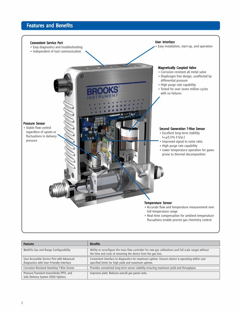
FeaturFeaturFeaturFeaturFeatures and Benefitses and Benefitses and Benefitses and Benefitses and Benefits
User InUser InUser InUser InUser Interfaceterfaceterfaceterfaceterface• Easy installation, start-up, and operation
Magnetically Coupled Magnetically Coupled Magnetically Coupled Magnetically Coupled Magnetically Coupled VVVVValvealvealvealvealve• Corrosion resistant all metal valve• Diaphragm free design, unaffected by
differential pressure• High purge rate capability• Tested for over seven million cycles
with no failures
TTTTTemperemperemperemperemperaturaturaturaturature Sensore Sensore Sensore Sensore Sensor• Accurate flow and temperature measurement over
full temperature range• Real-time compensation for ambient temperature
flucuations enable precise gas chemistry control
ConConConConConvenienvenienvenienvenienvenient Service Pt Service Pt Service Pt Service Pt Service Portortortortort• Easy diagnostics and troubleshooting• Independent of tool communication
PrPrPrPrPressuressuressuressuressure Sensore Sensore Sensore Sensore Sensor• Stable flow control
regardless of upsets orfluctuations in deliverypressure
MultiFlo Gas and Range Configurability Ability to reconfigure the mass flow controller for new gas calibrations and full scale ranges withoutthe time and costs of removing the device from the gas line.
User Accessible Service Port with Advanced Convenient interface to diagnostics for maximum uptime. Ensures device is operating within userDiagnostics with User-Friendly Interface specified limits for high yield and maximum uptime.
Corrosion Resistant Hastelloy T-Rise Sensor Provides unmatched long-term sensor stability ensuring maximum yield and throughput.
Pressure Transient Insensitivity (PTI), and Improves yield. Reduces overall gas panel costs.Safe Delivery System (SDS) Options
3
Ultra Fast ResponseUltra Fast ResponseUltra Fast ResponseUltra Fast ResponseUltra Fast ResponseBy combining Brooks' patented flow sensor technology with ahigh speed ARM processor and fast acting diaphragm free valveassembly, the GF100 Series delivers up to 3 times fasterresponse and settling time compared to other mass flowcontrollers, enabling:
• Improved wafer throughput by reducing nonproductive flow
settling steps
• Critical Etch processes requiring ultrafast 1-2 second etch steps
• Reduced diverted gas consumption and associated
abatement costs
• Time-sensitive gas delivery steps in Atomic Layer Deposition
• For processes requiring a slow ramped gas turn-on or time
critical transitions between flow rates. A user programmableramp function is provided
MultiFloMultiFloMultiFloMultiFloMultiFlo™ Gas and Range Configurability Gas and Range Configurability Gas and Range Configurability Gas and Range Configurability Gas and Range ConfigurabilityA major advancement over traditional single point gasconversion factors, Brooks MultiFlo technology delivers up to athree-times improvement in process gas accuracy. This isachieved through advanced gas modeling optimized throughactual gas testing providing compensation for non-linear gases.MultiFlo also allows the device to be quickly and easilyconfigured for another gas and/or flow range withoutsacrificing accuracy or rangability. Selecting a new gasautomatically creates a new calibration curve, establishesoptimized PID settings for dynamic control, automaticallycompensates for gas density effects, and ensures smooth,overshoot-free transitions between flow rates with excellentsteady-state stability.
Brooks MultiFlo technology offers unparalleled flexibility; asingle device can be programmed for thousands of differentgas and flow range configurations.
Re-programming is simple and fast; a new gas and range canbe programmed in under 30 seconds. Brooks provides a fullgas database to ensure the true value of MultiFlo is realized:
• Dramatically reduces inventory costs
• Mass flow controller full scale flow range can re-scaled down
typically by a factor of 3:1 with no impact on accuracy,turndown or leak by specifications, for optimum process andinventory flexibility
• Up to 40% fewer configurations required to support typical
etch and CVD processes verses our closest competitor
• Widest process gas coverage through extensive gas library
• Mass flow controllers can be replaced in only a few minutes
• Off-the shelf spares programmability enables rapid process
778Z011ZZZ778Z011ZZZ778Z011ZZZ778Z011ZZZ778Z011ZZZ Basic MultiFlo Configurator KitBasic MultiFlo Configurator KitBasic MultiFlo Configurator KitBasic MultiFlo Configurator KitBasic MultiFlo Configurator Kitw/Power Supply and Adapter Cablesw/Power Supply and Adapter Cablesw/Power Supply and Adapter Cablesw/Power Supply and Adapter Cablesw/Power Supply and Adapter Cables*Software, MultiFlo Configurator
A331710003 Cable Assembly 2.5mm214F027AAA USB-RS485 Converter with DB-9 femaleA332295001 Power Supply MFCA332297002 Cable, Power, 9-PinA332297001 Cable, Power, DeviceNet
* MultiFlo Configurator Software is available on the BrooksInstrument website at: www.BrooksInstrument.com/MultiFlo
Pressure Transient Insensitivity (PTI) (GF125 only)Pressure Transient Insensitivity (PTI) (GF125 only)Pressure Transient Insensitivity (PTI) (GF125 only)Pressure Transient Insensitivity (PTI) (GF125 only)Pressure Transient Insensitivity (PTI) (GF125 only)Cost and space constraints are driving gas panel designers toremove point of use pressure regulators and pressuremonitoring components, placing more burden on the mass flowcontroller to control accurately under dynamic pressureconditions. Conventional mass flow controllers react strongly tosmall inlet pressure fluctuations resulting in unstableperformance and unpredictable accuracy (see Non-PressureInsensitive MFC). This drove Brooks to develop PressureTransient Insensitive mass flow controller technology (PTI-MFC).
The GF125 PTI-MFC is a second generation PTI-MFC utilizing apatented control algorithm that inverts the pressure signal,compares it to the pre-fluctuation signal and drives real-timevalve position compensation to maintain stable flow. Enhancedpressure transient insensitivity is achieved through fastersensing, faster processing, and a reduction in internal dead-volume between the sensors and valve orifice.
Extensive Mechanical Configuration SupportExtensive Mechanical Configuration SupportExtensive Mechanical Configuration SupportExtensive Mechanical Configuration SupportExtensive Mechanical Configuration SupportGF100 Series supports all metal seal / UHP industry gasconnection interface standards for full OEM and process coverage
• Downport 80mm and 92mm C-seal and W-Seal, on 1.125" and
1.5" bodies
• Downport 80mm CS seal on 1.5" body
• 124 mm 1/4” VCR Male on 1.5" body
Enhanced DiagnosticsEnhanced DiagnosticsEnhanced DiagnosticsEnhanced DiagnosticsEnhanced DiagnosticsThe mass flow controller remains the most complex and criticalcomponent in gas delivery systems. When dealing with UHP gasdistribution or highly toxic or corrosive gases, removing the massflow controller to determine if it is faulty should be the last resort.In response to this, Brooks pioneered smarter mass flow controllerswith embedded self test routines and introduced an independentdiagnostic/service port to provide the user with a simple interface,for troubleshooting without disturbing flow controller operation.
User InterfaceUser InterfaceUser InterfaceUser InterfaceUser InterfaceThe user interface has a high visibility LCD display that providesa local indication of Flow (%), Temperature (°C), Pressure (PSIA/KPa) and Network Address, selectable through the Display button.A Zero button provides a simple means to re-zero the mass flowcontroller as part of scheduled maintenance.
Communication InterfaceCommunication InterfaceCommunication InterfaceCommunication InterfaceCommunication InterfaceThe GF100 Series supports analog 0-5 Vdc, RS485, andDeviceNet™ communication protocols. A range of low profileadapter cables facilitate replacing older mass flow controllerswith the GF100 Series eliminating the need to carry mass flowcontrollers of same gas/range but different electrical connectors.
Digital Communication Digital Communication Digital Communication Digital Communication Digital Communication RS485+ (model specific), DeviceNet (model specific), RS485 Diagnostic Port (all models)
Diagnostic /Service Port Diagnostic /Service Port Diagnostic /Service Port Diagnostic /Service Port Diagnostic /Service Port RS485 via 2.5mm jack
Power Supply/Consumption Power Supply/Consumption Power Supply/Consumption Power Supply/Consumption Power Supply/Consumption DeviceNet: 545mA max. @ +11-25 Vdc., 250mA max. @ 24VdcRS485/Analog: 6 Watts max @ +15Vdc. (+10%) or +24 Vdc (±10%)
PerformancePerformancePerformancePerformancePerformanceFull Scale Flow Range (NFull Scale Flow Range (NFull Scale Flow Range (NFull Scale Flow Range (NFull Scale Flow Range (N
Normally Open ValveNormally Open ValveNormally Open ValveNormally Open ValveNormally Open Valve <1.5 sec
Pressure InsensitivityPressure InsensitivityPressure InsensitivityPressure InsensitivityPressure Insensitivity Not Applicable < 5% SP up to 5 psi/sec upstream press. spike
Control RangeControl RangeControl RangeControl RangeControl Range 2-100% (Normally Closed Valve) 3-100% (Normally Open Valve)
MultiFloMultiFloMultiFloMultiFloMultiFlo standard
#of Bins#of Bins#of Bins#of Bins#of Bins 11 bins
Valve Shut Down (N.C. Valve)Valve Shut Down (N.C. Valve)Valve Shut Down (N.C. Valve)Valve Shut Down (N.C. Valve)Valve Shut Down (N.C. Valve) < 1% of F.S.Valve Shut Down (N.O. Valve)Valve Shut Down (N.O. Valve)Valve Shut Down (N.O. Valve)Valve Shut Down (N.O. Valve)Valve Shut Down (N.O. Valve) 2% of F.S.
Zero StabilityZero StabilityZero StabilityZero StabilityZero Stability < + 0.5% F.S. per year
Temperature CoefficientTemperature CoefficientTemperature CoefficientTemperature CoefficientTemperature Coefficient Span: 0.05% S.P. per oC, Zero: 0.005% F.S. per oC
RatingsRatingsRatingsRatingsRatingsOperating Temperature RangeOperating Temperature RangeOperating Temperature RangeOperating Temperature RangeOperating Temperature Range 10-50oC
Differential Pressure Range*Differential Pressure Range*Differential Pressure Range*Differential Pressure Range*Differential Pressure Range* 3-860 sccm = 7-45 psid, 861- 7200 sccm = 10-45 psid, 7201-55000 sccm = 15-45 psid *Argon gas applications require an additional 10 psid differential pressure. Low vapor pressure gases require an inlet pressure of > 100 Torr, with vacuum on outlet (example SiCl4). Contact Brooks Technical Support for more information.
Maximum Operating PressureMaximum Operating PressureMaximum Operating PressureMaximum Operating PressureMaximum Operating Pressure 500 psia max 100 psia max
*Performance at minimum inlet pressure will be gas and flow range dependent. Consult Technical Support for details.**Typical pressure drop. Actual pressure drop will be gas and flow dependent. Consult Technical Support for details.***Consult factory for other gases.
PrPrPrPrProduct Specifications (GF120XSD and GF120XSL) Optionsoduct Specifications (GF120XSD and GF120XSL) Optionsoduct Specifications (GF120XSD and GF120XSL) Optionsoduct Specifications (GF120XSD and GF120XSL) Optionsoduct Specifications (GF120XSD and GF120XSL) Options
PrPrPrPrProduct Description GF120 Safe Delivery System (SDSoduct Description GF120 Safe Delivery System (SDSoduct Description GF120 Safe Delivery System (SDSoduct Description GF120 Safe Delivery System (SDSoduct Description GF120 Safe Delivery System (SDS ) Option) Option) Option) Option) Option®®®®®
Full Scale Flow Range (NFull Scale Flow Range (NFull Scale Flow Range (NFull Scale Flow Range (NFull Scale Flow Range (N22222 Eq.) Eq.) Eq.) Eq.) Eq.) 4 - 25 sccm >25 to 1 slpm
Zero StabilityZero StabilityZero StabilityZero StabilityZero Stability <=0.6% F.S. per year
Settling Time (to within Settling Time (to within Settling Time (to within Settling Time (to within Settling Time (to within +++++2% F.S.)2% F.S.)2% F.S.)2% F.S.)2% F.S.) < 3 sec
Warm Up TimeWarm Up TimeWarm Up TimeWarm Up TimeWarm Up Time minimum of 30 minutes
Leak IntegrityLeak IntegrityLeak IntegrityLeak IntegrityLeak Integrity 1X10-11 atm. cc/sec He
Valve Shut Down (Leaky by)Valve Shut Down (Leaky by)Valve Shut Down (Leaky by)Valve Shut Down (Leaky by)Valve Shut Down (Leaky by) <1% F.S.
Ambient Temperature RangeAmbient Temperature RangeAmbient Temperature RangeAmbient Temperature RangeAmbient Temperature Range 10OC-50OC
Zero Temperature CoefficientZero Temperature CoefficientZero Temperature CoefficientZero Temperature CoefficientZero Temperature Coefficient Span: 0.05% SP per OC, Zero: 0.005% F.S. per OC
The GF120 Safe Delivery System (SDSGF120 Safe Delivery System (SDSGF120 Safe Delivery System (SDSGF120 Safe Delivery System (SDSGF120 Safe Delivery System (SDS®®®®®) ) ) ) ) is Brooks’ state-of-the-art lowpressure drop mass flow controller for the delivery of sub atmosphericsafe delivery system (SDS) gases used in Implant and Etch processes. TheBrooks GF120 (SDS) models are available in full scale flow ranges 4-25sccm (option GF120XSL) or >25 sccm to 1 slpm (option GF120XSD).
These expensive, hazardous gases are adsorbed onto a solid mediumwithin the gas cylinder, remaining below atmospheric pressure despitecontaining up to 15 times more dopant than conventional pressurizedsources.
The amount of gas that can be extracted from the SDS controlled cylinderis highly dependent upon the final cylinder pressure. This is illustrated inSDS desorption species information in the SDS Gas Use Rate EfficiencyCurve. Most of the gas is released at pressures below 100 Torr. Theminimum cylinder pressure that can be reached is limited by theconductance of the mass flow controller regulating the flow. Most massflow controllers require a 50 Torr differential pressure at flow rates of 5sccm. At this 50 Torr limit, only ~65% of the dopant can be extractedfrom the adsorbent medium at normal operating temperatures. TheGF120 (SDS)GF120 (SDS)GF120 (SDS)GF120 (SDS)GF120 (SDS) low pressure operation enables a further 30% of thedopant to be extracted, driving significant cost savings in SDS gasesand equipment OEE.
8
I/O Options Using Base Model and Adapter Cable
A range of low profile adapter cables have been developed to supportreplacing older generation MFC's with different pinout configurations.The base MFC will be either a G1, TX or SX configuration, depending onthe product being replaced.
PDC OrPDC OrPDC OrPDC OrPDC Ordering Code: EXdering Code: EXdering Code: EXdering Code: EXdering Code: EXDescription: GX base I/O with7003083 adapter for compatibilitywith Unit “E”, IN “L”, “R”
PDC OrPDC OrPDC OrPDC OrPDC Ordering Code: KXdering Code: KXdering Code: KXdering Code: KXdering Code: KXDescription: G1 base I/O with7003298 adapter for compatibilitywith Unit UDK15
PDC OrPDC OrPDC OrPDC OrPDC Ordering Code UXdering Code UXdering Code UXdering Code UXdering Code UXDescription: SX base I/O with7003550 adapter forcompatibility with Unit UDU15
PDC OrPDC OrPDC OrPDC OrPDC Ordering Code: FX / dering Code: FX / dering Code: FX / dering Code: FX / dering Code: FX / JXJXJXJXJXDescription: SX base I/O with7003069 (FX)/7001814 (JX)adapter for compatibility withUnit UDF9/UDJ9
PDC OrPDC OrPDC OrPDC OrPDC Ordering Code: Bdering Code: Bdering Code: Bdering Code: Bdering Code: BXXXXXDescription: G1 base I/O with7003590 adapter forcompatibility with Brooks 15-Pin D
Other adapter options arOther adapter options arOther adapter options arOther adapter options arOther adapter options are available for the GF Series. Please cone available for the GF Series. Please cone available for the GF Series. Please cone available for the GF Series. Please cone available for the GF Series. Please contact Brtact Brtact Brtact Brtact BrooksooksooksooksooksCustomer Service for morCustomer Service for morCustomer Service for morCustomer Service for morCustomer Service for more ine ine ine ine information.formation.formation.formation.formation.
PDC OrPDC OrPDC OrPDC OrPDC Ordering Code dering Code dering Code dering Code dering Code TXTXTXTXTXDescription: Industry standardAnalog only interface
PDC OrPDC OrPDC OrPDC OrPDC Ordering Code BBdering Code BBdering Code BBdering Code BBdering Code BBDescription: Industry standardODVA compliant DeviceNetinterface, Plus a separateAnalog 0-5 Vdc Connector
PDC OrPDC OrPDC OrPDC OrPDC Ordering Code SXdering Code SXdering Code SXdering Code SXdering Code SXDescription: Industry standardAnalog 9-Pin Sub D connectorand dual RJ11 RS485 ports
All Base I/O options include:All Base I/O options include:All Base I/O options include:All Base I/O options include:All Base I/O options include:Diagnostic port communication RS485 via 2.5mm jacDiagnostic port communication RS485 via 2.5mm jacDiagnostic port communication RS485 via 2.5mm jacDiagnostic port communication RS485 via 2.5mm jacDiagnostic port communication RS485 via 2.5mm jackkkkk
Model CodeModel CodeModel CodeModel CodeModel Code
Code DescriptionCode DescriptionCode DescriptionCode DescriptionCode Description Code OptionCode OptionCode OptionCode OptionCode Option Option DescriptionOption DescriptionOption DescriptionOption DescriptionOption DescriptionI.I.I.I.I. Base Model Code GFGFGFGFGF High Purity/Ultra High Purity Digital Mass Flow Controllers
III.III.III.III.III. Configurability CCCCC MultiFlo capable. Standard bins or specific gas/range may be selected.XXXXX Not MultiFlo capable. Specific gas/range required. (must select w/ SD, SL or HA special application)
IV.IV.IV.IV.IV. Special Application XXXXXXXXXX StandardSLSLSLSLSL Safe Delivery System (GF120 Only) Full scale flow range; 4 to 25 sccm, Nitrogen EquivalentSDSDSDSDSD Safe Delivery System (GF120 Only) Full scale flow range; >25 sccm to 1 slpm, Nitrogen Equivalent
V.V.V.V.V. Valve Configuration OOOOO Normally Open valve (not available with SD, SL or HA options)CCCCC Normally Closed valve (must select with SD, SL or HA special application)MMMMM Meter (No Valve)
VI.VI.VI.VI.VI. Gas or SH MultiFlo Bin XXXX XXXXXXXX XXXXXXXX XXXXXXXX XXXXXXXX XXXX Specific Gas Code & Range, i.e. “0004” = Argon and “010L” = 10 slpm (must select w/ SD, SL orHA special application).
SH40 010CSH40 010CSH40 010CSH40 010CSH40 010C Standard Configuration #40, 3-10 sccm Nitrogen Equivalent (0° C Reference)SH41 030CSH41 030CSH41 030CSH41 030CSH41 030C Standard Configuration #41, 11-30 sccm Nitrogen Equivalent (0° C Reference)SH42 092CSH42 092CSH42 092CSH42 092CSH42 092C Standard Configuration #42, 31-92 sccm Nitrogen Equivalent (0° C Reference)SH43 280CSH43 280CSH43 280CSH43 280CSH43 280C Standard Configuration #43,93-280 sccm Nitrogen Equivalent (0° C Reference)SH44 860CSH44 860CSH44 860CSH44 860CSH44 860C Standard Configuration #44, 281-860 sccm Nitrogen Equivalent (0° C Reference)SH45 2.6LSH45 2.6LSH45 2.6LSH45 2.6LSH45 2.6L Standard Configuration #45, 861-2600 sccm Nitrogen Equivalent (0° C Reference)SH46 7.2LSH46 7.2LSH46 7.2LSH46 7.2LSH46 7.2L Standard Configuration #46, 2601-7200 sccm Nitrogen Equivalent (0° C Reference)SH47 015LSH47 015LSH47 015LSH47 015LSH47 015L Standard Configuration #47, 7201-15000 sccm Nitrogen Equivalent (0° C Reference)SH48 030LSH48 030LSH48 030LSH48 030LSH48 030L Standard Configuration #48, 15001-30000 sccm Nitrogen Equivalent (0° C Reference)SH49 040LSH49 040LSH49 040LSH49 040LSH49 040L Standard Configuration #49, 30001-40000 sccm Nitrogen Equivalent (0° C Reference)SH50 055LSH50 055LSH50 055LSH50 055LSH50 055L Standard Configuration #50, 40001-55000 sccm Nitrogen Equivalent (0° C Reference)
VII.VII.VII.VII.VII. Fitting VXVXVXVXVX 1-1/2” body width, 124mm 1/4” VCR maleVSVSVSVSVS 1-1/8” body width, 124mm 1/4” VCR maleCXCXCXCXCX 1-1/8” body width, 92mm C SealDXDXDXDXDX 1-1/8” body width, 79.8mm C SealEXEXEXEXEX 1-1/2” body width, 79.8mm W SealWXWXWXWXWX 1-1/8” body width, 92mm W SealYXYXYXYXYX 1-1/8” body width, 79.8mm W SealAXAXAXAXAX 1-1/2” body width, 92mm C SealBXBXBXBXBX 1-1/2” body width, 92mm W SealLXLXLXLXLX 1-1/8” body width, 92mm C Seal w/Poke YokeASASASASAS 1-1/2” body width, 92mm 0.440” large bore C Seal (only for bins SH45-SH50)
VIII.VIII.VIII.VIII.VIII. Downstream Condition AAAAA AtmosphereVVVVV Vacuum; Default for SD, SL and HA special application
IX.IX.IX.IX.IX. Sensor OOOOO Default Sensor OrientationModel Code continued on next page.
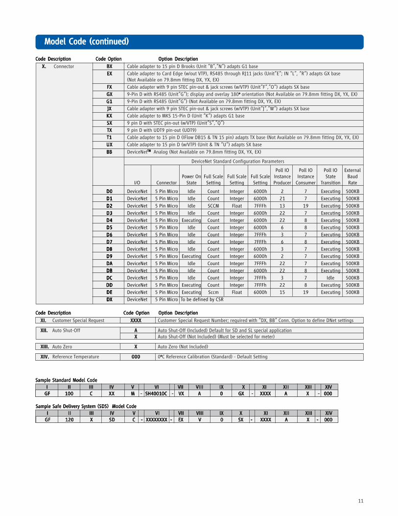
XI.XI.XI.XI.XI. Customer Special Request XXXXXXXXXXXXXXXXXXXX Customer Special Request Number; required with “DX, BB” Conn. Option to define DNet settings
XII.XII.XII.XII.XII. Auto Shut-Off AAAAA Auto Shut-Off (Included) Default for SD and SL special applicationXXXXX Auto Shut-Off (Not Included) (Must be selected for meter)
XIII.XIII.XIII.XIII.XIII. Auto Zero XXXXX Auto Zero (Not Included)
Sample Standard Model CodeSample Standard Model CodeSample Standard Model CodeSample Standard Model CodeSample Standard Model Code
IIIII IIIIIIIIII IIIIIIIIIIIIIII IVIVIVIVIV V VI VII V VI VII V VI VII V VI VII V VI VII VIIIVIIIVIIIVIIIVIII IXIXIXIXIX XXXXX XI XI XI XI XI XIIXIIXIIXIIXII XIII XIV XIII XIV XIII XIV XIII XIV XIII XIV
GFGFGFGFGF 100100100100100 CCCCC XXXXXXXXXX M - M - M - M - M - SH40010C - SH40010C - SH40010C - SH40010C - SH40010C - VX VX VX VX VX AAAAA 00000 GX - GX - GX - GX - GX - XXXXXXXXXXXXXXXXXXXX AAAAA X - 000 X - 000 X - 000 X - 000 X - 000
Sample Safe Delivery System (SDS) Model CodeSample Safe Delivery System (SDS) Model CodeSample Safe Delivery System (SDS) Model CodeSample Safe Delivery System (SDS) Model CodeSample Safe Delivery System (SDS) Model Code
IIIII IIIIIIIIII IIIIIIIIIIIIIII IVIVIVIVIV VVVVV VIVIVIVIVI VII VII VII VII VII VIIIVIIIVIIIVIIIVIII IX X IX X IX X IX X IX X XIXIXIXIXI XIIXIIXIIXIIXII XIII XIV XIII XIV XIII XIV XIII XIV XIII XIV
GFGFGFGFGF 120120120120120 XXXXX SDSDSDSDSD C - C - C - C - C - XXXXXXXX - XXXXXXXX - XXXXXXXX - XXXXXXXX - XXXXXXXX - EX EX EX EX EX VVVVV 00000 SX - SX - SX - SX - SX - XXXXXXXXXXXXXXXXXXXX AAAAA X - 000 X - 000 X - 000 X - 000 X - 000
Brooks is committed to assuring all of our customers receive the ideal flow solution for their application, along with outstandingservice and support to back it up. We operate first class repair facilities located around the world to provide rapid response andsupport. Each location utilizes primary standard calibration equipment to ensure accuracy and reliability for repairs and recalibra-tion and is certified by our local Weights and Measures Authorities and traceable to the relevant International Standards.
Visit www.BrooksInstrument.com to locate the service location nearest to you.
STSTSTSTSTARARARARARTTTTT-UP SERVICE -UP SERVICE -UP SERVICE -UP SERVICE -UP SERVICE AND IN-SITU CALIBRAAND IN-SITU CALIBRAAND IN-SITU CALIBRAAND IN-SITU CALIBRAAND IN-SITU CALIBRATIONTIONTIONTIONTION
Brooks Instrument can provide start-up service prior to operation when required. For some process applications, where ISO-9001Quality Certification is important, it is mandatory to verify and/or (re)calibrate the products periodically. In many cases this servicecan be provided under in-situ conditions, and the results will be traceable to the relevant international quality standards.
CUSTCUSTCUSTCUSTCUSTOMER SEMINARS OMER SEMINARS OMER SEMINARS OMER SEMINARS OMER SEMINARS AND AND AND AND AND TRAININGTRAININGTRAININGTRAININGTRAINING
Brooks Instrument can provide customer seminars and dedicated training to engineers, end users, and maintenance persons.
Please contact your nearest sales representative for more details.
Due to Brooks Instrument's commitment to continuous improvement of our products, all specifications are subject to change
without notice.
BrBrBrBrBrooks Service and Supportooks Service and Supportooks Service and Supportooks Service and Supportooks Service and Support
TRADEMARKSBrooks is a trademark of Brooks Instrument, LLCAll other trademarks are the property of their respective owners.