Installation Manual Electric Range LRE30955S / LRE30855S LRE30755S / LRE30451S Please read these instructions thoroughly before installing and operating the range. P/No.: MFL37118101 Website: http://us.lge.com
Transcript
Installation ManualElectric Range
LRE30955S / LRE30855SLRE30755S / LRE30451S
Please read these instructions thoroughly beforeinstalling and operating the range.
P/No.: MFL37118101
Website: http://us.lge.com
2
Part 1 SAFETY
1 BEFORE YOU BEGIN
Remove all tape and packing materials before using the range. Dispose of all plastic bags after unpacking the range. Never allow children to play with packing materials.
IMPORTANT SAFETY INSTRUCTIONS
Read and follow all instructions before using your oven to prevent the risk of fire, electric shock, personal injury, ordamage when using the range. This guide does not cover all possible conditions that may occur. For furtherassistance contact your service agent or manufacturer.
This is the safety alert symbol. This symbol alerts you to potential hazards that can cause personal injury toyou and others. All safety messages will follow the safety alert symbol with either the word “WARNING” or“CAUTION”.
This symbol will alert you to hazards or unsafe practices which could cause seriousbodily harm or death.WARNING
This symbol will alert you to hazards or unsafe practices which could cause bodilyinjury or property damage.CAUTION
WARNING• The information in this manual should be followed exactly.- A fire or electrical shock may result causing property damage, perasonal injury or death.• DO NOT step or sit on oven door. Install the Anti-Tip Bracket supplied with the range.- The range could be tipped and injury might result from spilled hot liquid, food, or the range itself.- If the range is pulled away from the wall for cleaning, service, or any other reason, ensure that the Anti-Tip Device is properlyreengaged when the range is pushed back against the wall.
• New branch-circuit installations (1996 NEC) for mobile homes, recreational vehicles, andinstallations where local codes do not allow grounding through the neutral wire require a 4-conductor UL listed range cord or 4 wire conduit connection.
• The middle (neutral or ground) wire of a 3 wire power cord or a 3 wire conduit has to be connectedto the middle post of the main terminal block. The remaining two wires of the power cord orconduit have to be connected to the outside posts of the main terminal connection block.
- Failure to do so can result in electrical shock, severe personal injury or death.• Only a 4-conductor power-supply cord kit rated 120/240 volts, 50 amperes and marked for use with
ranges with closed-loop connectors or open-end spade lugs with upturned ends shall be used.The middle (neutral) wire of the power cord or 4-wire conduit has to be connected to the middlepost of the main terminal block. The other two wires of the power cord or conduit have to beconnected to the outside posts of the main terminal connection block. The 4th ground wire mustbe connected to the frame of the range with the ground screw.
- Failure to do so can result in electrical shock, severe personal injury or death.
CAUTION• Make sure that the wall covering, countertop and cabinets around the range can withstand
the heat (up to 194°F) generated by the range.- Discoloration, delamination or melting may occur.- This range has been designed to comply with the maximum allowable wood cabinet temperatures of 194°F.
• Cabinet storage space located above the surface units should be avoided.• Install a range hood that projects horizontally a minimum of 5 inches beyond the bottom of
the cabinets If cabinet storage is to be provided.- The risk of burns or fire by reaching over the heated surface elements can be reduced.
3
Part 1 SAFETY
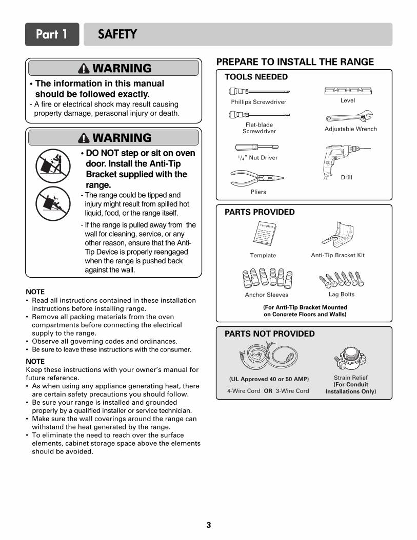
PARTS PROVIDED
NOTE
• Read all instructions contained in these installationinstructions before installing range.
• Remove all packing materials from the ovencompartments before connecting the electricalsupply to the range.
• Observe all governing codes and ordinances.• Be sure to leave these instructions with the consumer.
NOTE
Keep these instructions with your owner’s manual forfuture reference.• As when using any appliance generating heat, there
are certain safety precautions you should follow. • Be sure your range is installed and grounded
properly by a qualified installer or service technician.• Make sure the wall coverings around the range can
withstand the heat generated by the range.• To eliminate the need to reach over the surface
elements, cabinet storage space above the elementsshould be avoided.
TOOLS NEEDED
PREPARE TO INSTALL THE RANGE
PARTS NOT PROVIDED
WARNING• The information in this manual
should be followed exactly.- A fire or electrical shock may result causing
property damage, perasonal injury or death.
WARNING• DO NOT step or sit on oven
door. Install the Anti-TipBracket supplied with therange.
- The range could be tipped andinjury might result from spilled hotliquid, food, or the range itself.
- If the range is pulled away from thewall for cleaning, service, or anyother reason, ensure that the Anti-Tip Device is properly reengagedwhen the range is pushed backagainst the wall.
(For Anti-Tip Bracket Mounted
on Concrete Floors and Walls)
INSTALLATION DRAWINGS
NOTE
SAVE FOR THE USE OF THE LOCAL ELECTRICAL INSPECTOR.
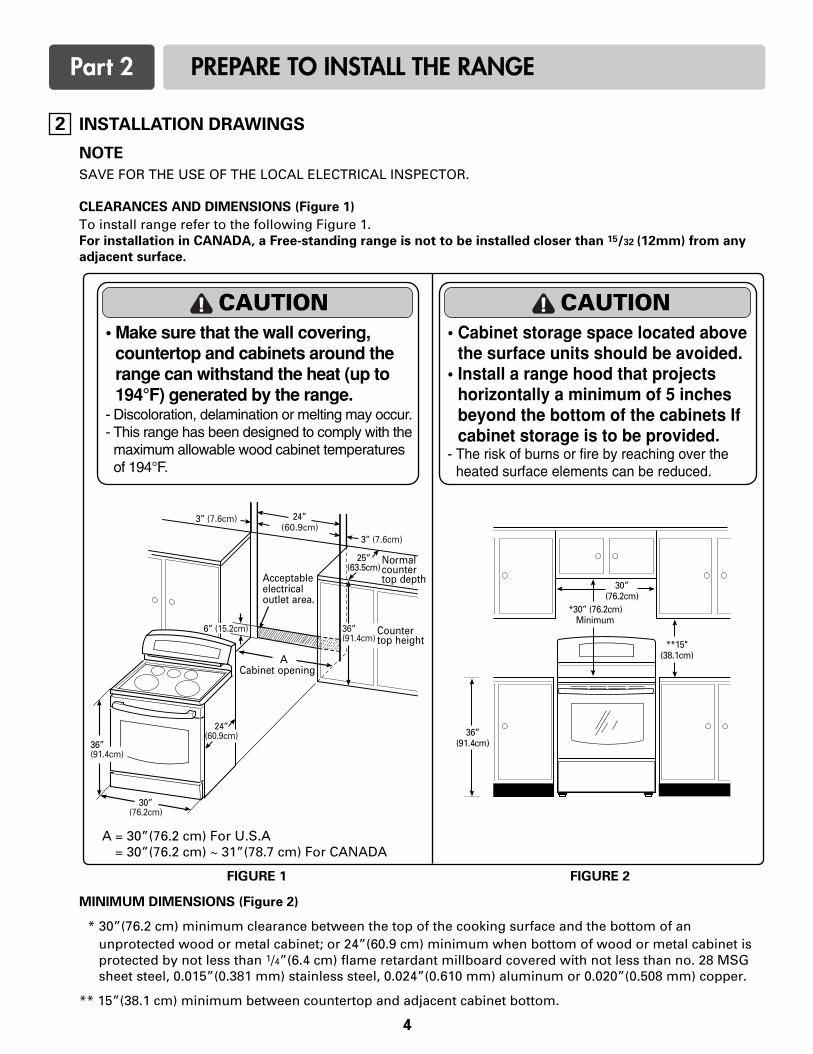
CLEARANCES AND DIMENSIONS (Figure 1)
To install range refer to the following Figure 1.For installation in CANADA, a Free-standing range is not to be installed closer than 15/32 (12mm) from any
adjacent surface.
MINIMUM DIMENSIONS (Figure 2)
* 30”(76.2 cm) minimum clearance between the top of the cooking surface and the bottom of anunprotected wood or metal cabinet; or 24”(60.9 cm) minimum when bottom of wood or metal cabinet isprotected by not less than 1/4”(6.4 cm) flame retardant millboard covered with not less than no. 28 MSGsheet steel, 0.015”(0.381 mm) stainless steel, 0.024”(0.610 mm) aluminum or 0.020”(0.508 mm) copper.
** 15”(38.1 cm) minimum between countertop and adjacent cabinet bottom.
FIGURE 1 FIGURE 2
A = 30”(76.2 cm) For U.S.A= 30”(76.2 cm) ~ 31”(78.7 cm) For CANADA
CAUTION• Make sure that the wall covering,
countertop and cabinets around therange can withstand the heat (up to194°F) generated by the range.
- Discoloration, delamination or melting may occur.- This range has been designed to comply with themaximum allowable wood cabinet temperaturesof 194°F.
CAUTION• Cabinet storage space located above
the surface units should be avoided.• Install a range hood that projects
horizontally a minimum of 5 inchesbeyond the bottom of the cabinets Ifcabinet storage is to be provided.
- The risk of burns or fire by reaching over theheated surface elements can be reduced.
4
2
Part 2 PREPARE TO INSTALL THE RANGE
The Cord/Conduit connection plate is used for theinstallation of power cord or conduit. For power cord,install it with the connection plate as INSTALLED. Forconduit, remove the connection plate located belowthe rear of the drawer body and use the conduit hole(11/8”) instead of power cord hole (13/8”).(Refer to Figure 5 and 6.)
3, 4 - Wire electrical wall Receptacle
5
3 CONNECT RANGE CORD
The Rear Access cover must be removed. Loosen thethree screws with a screwdriver. The terminal blockwill then be accessible.
4
FIGURE 3
FIGURE 4
Range rating, watts Specified ratingof power-supply-cord kit, amperes120/240 volts
3-wire
8,750 - 16,50016,501 - 22,500
120/208 volts3-wire
7,801 - 12,50012,501 - 18,500
40 or 50A50
Diameter (inches) of Rangeconnection Opening
Conduit
11/8”11/8”
Power cord
13/8”13/8”
Specified power-supply-cord kit rating
Part 3 ELECTRICAL CONNECTIONS
ELECTRICAL CONNECTION
REQUIREMENTS
This appliance must be installed and grounded on abranch circuit by a qualified technician in accordancewith the National Electrical code ANSI/NFPA NO. 70 -latest edition.
All wiring should conform to Local and NEC. Thisrange requires a single-phase, 3 wire, A.C 120/208V or120/240V 60Hz electrical system. Use only a 3-conductoror a 4-conductor UL-listed range cord with closed-loop terminals, open-end spade lugs with upturnedends or similar terminations. Cord must have thestrain relief properly installed.
A range cord rated at 40 amps with 120/240 minimumvolt range is required. If a 50 amp range cord is used,it should be marked for use with 13⁄8” diameterconnection openings.
This appliance may be connected by means of conduitor power cord. If conduit is being used, go to page 7 3 wire conduit connections or page 8 for 4 wire
conduit connections.
4 Wire receptacle (14-50R)
3 Wire receptacle (10-50R)
WARNING• New branch-circuit installations (1996 NEC)
for mobile homes, recreational vehicles,and installations where local codes do notallow grounding through the neutral wirerequire a 4-conductor UL listed range cordor 4 wire conduit connection. FIGURE 5
FIGURE 6
Remove the Conduit connection plate
Assemble the strain relief hole
Reinstall the Cord/Conduit connection plate
6
Part 3 ELECTRICAL CONNECTIONS
FIGURE 7
FIGURE 8
3-wire connection
Assemble the strain relief to the 1 3/8” opening in
Conduit connection plate
Separate Strain Reliefbefore installation
3-wire connection with a power supply cord
WARNING• The middle (neutral or ground) wire of a 3
wire power cord or a 3 wire conduit has tobe connected to the middle post of themain terminal block. The remaining twowires of the power cord or conduit have tobe connected to the outside posts of themain terminal connection block.
- Failure to do so can result in electrical shock, severepersonal injury or death.
Install the power cord as follows:For power cord installations, Hook the strain reliefover the power cord hole (13/8”) located below the rearof drawer body. Insert the power cord through thestrain relief and tighten it. (Refer to Figure 7.)
You must install the power cord with a strain relief.
1. Remove the lower 3 screws from the terminal blockand retain them. (Refer to Figure 8.)
2. Insert the 3 screws through each power cordterminal ring and into the lower terminals of theterminal block. Make sure that the center wire (white/neutral) isconnected to the center lower position of theterminal block.
3. Tighten 3 screws securely into the terminal block.Do not remove the ground strap connections.
4. Go to page 9.
7
Part 3 ELECTRICAL CONNECTIONS
Follow the instructions under “ CONNECT RANGECORD” on page 5 to correctly install the strain relief.
1. Remove the lower 3 screws from the terminal blockand retain them. (Refer to Figure 9.)Remove the ground screw and retain it.
2. Remove ground strap and discard as shown in Figure 9. Do not discard any screws.
3. Insert the ground screw into the power cord groundwire terminal ring and secure it to the range frame.
4. Insert the 3 screws through each power cordterminal ring and into the lower terminals of theterminal block. Make sure that the center wire(white/neutral) is connected to the center lowerposition of the terminal block.Tighten 3 screws securely into the terminal block.
5. Go to page 9.
Install the conduit as follows:
Remove the Conduit connection plate from the rear ofdrawer body and rotate it as shown in Figure 5. Theconduit hole (11/8”) must be used.
First, prepare conduit wires as shown in Figure 10.
Second, install conduit as shown in Figure 6.
For conduit installations, after purchasing a strainrelief, insert it in the conduit hole (11/8”). Then installthe conduit through the body of strain relief andfasten the strain relief with its ring. Reinstall thebracket.
For conduit connections :If the wire in the conduit is copper it must be 8 or 10AWG wiring.If the wire in the conduit is aluminum it must be 6 or 8AWG wiring.
1. Loosen the lower 3 screws from the terminal block.(Refer to Figure 11.)
2. Insert the bare wire (white/neutral) end through thecenter terminal block opening. Do not remove ground strap connections.
3. Insert the two side bare wire ends into the lower leftand the lower right terminal block opening. Tighten the 3 screws securely into the terminal block.(approximately 35 - 50 IN-LB)
4. Go to page 9.
FIGURE 10
3-wire connection: conduit
or
3 wire 4 wire
FIGURE 9
4-wire connection
4-wire connection with a power supply cord
WARNING• Only a 4-conductor power-supply cord kit
rated 120/240 volts, 50 amperes andmarked for use with ranges with closed-loop connectors or open-end spade lugswith upturned ends shall be used. Themiddle (neutral) wire of the power cord or4-wire conduit has to be connected to themiddle post of the main terminal block. Theother two wires of the power cord orconduit have to be connected to theoutside posts of the main terminalconnection block. The 4th ground wiremust be connected to the frame of therange with the ground screw.
- Failure to do so can result in electrical shock, severepersonal injury or death.
4
FIGURE 11
3-wire connection
8
Part 3 ELECTRICAL CONNECTIONS
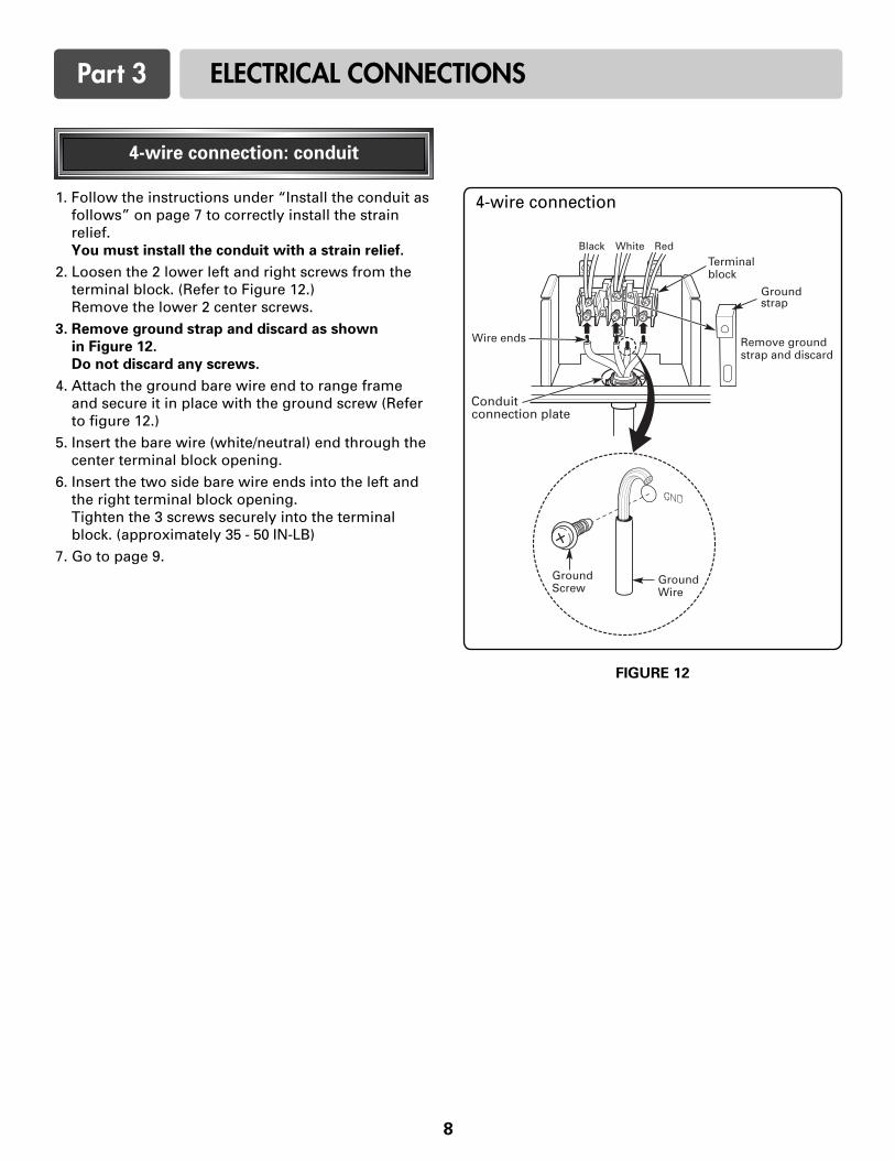
1. Follow the instructions under “Install the conduit asfollows” on page 7 to correctly install the strainrelief. You must install the conduit with a strain relief.
2. Loosen the 2 lower left and right screws from theterminal block. (Refer to Figure 12.)Remove the lower 2 center screws.
3. Remove ground strap and discard as shown
in Figure 12.
Do not discard any screws.
4. Attach the ground bare wire end to range frameand secure it in place with the ground screw (Referto figure 12.)
5. Insert the bare wire (white/neutral) end through thecenter terminal block opening.
6. Insert the two side bare wire ends into the left andthe right terminal block opening. Tighten the 3 screws securely into the terminalblock. (approximately 35 - 50 IN-LB)
7. Go to page 9.
FIGURE 12
4-wire connection
4-wire connection: conduit
Replace the access cover on the range back. Toreplace the wire cover, insert double projections in thepockets located below the opening and tighten thethree screws.
ANTI-TIP DEVICE INSTALLATION
NOTE
To install Anti-tip bracket, release the leveling leg. Aminimum clearance of 0.65”(16.5mm) is requiredbetween the range bottom and the kitchen floor.
1. Locate the bracket using the template
An Anti-tip bracket is packaged with template. Theinstructions include necessary information tocomplete the installation. Read and follow range installation instruction sheet(template).
2. Level the range
Level the range by adjusting the leveling legs with awrench.
9
Use a spirit level to check your adjustments. Place thelevel diagonally on the oven rack, and check eachdirection for level.
First check direction 1 .
After check direction 2 .
If the spirit level doesn’t show level on the rack, adjust the leveling legs with a wrench.
FINAL INSTALLATION
• Move range close enough to the opening to pluginto the receptacle.
• Slide range into position insuring that the left backleg slides under the anti-tip bracket. Range will sit 0”away from the back wall when properly installed.
• Carefully tip range forward to insure that the anti-tipbracket engages the range back brace and preventstip-over.
• Turn on electrical power. Check range for properoperation as described in owner’s manual.
5
6
Part 4 INSTALL THE RANGE
WARNING• DO NOT step or sit on oven
door. Install the Anti-TipBracket supplied with therange.
- The range could be tipped andinjury might result from spilled hotliquid, food, or the range itself.
- If the range is pulled away from thewall for cleaning, service, or anyother reason, ensure that the Anti-Tip Device is properly reengagedwhen the range is pushed backagainst the wall.


![The Solar Oven Experiment[1]](https://static.documents.pub/doc/80x56/58ee32c81a28ab93788b45f7/the-solar-oven-experiment1.jpg)


