Date 25.04.03 The PRT Project – Phase 1 D&E Page 1 of 29 Version 1.0 Company: Timebox AS DocID 1-ABC-3-4-1.0 Responsible: Jan Even Evensen The PRT Project Phase 1 Design & Engineering Overall System Design Title/Name of delivery: Overall System Design Document ID: 1-ABC-3-4-1.0 Version: 1.0 Date: 25.04.03 Company: Timebox AS Author: Jan Even Evensen Approved by: Jan Magnussen Security: Confidential
Transcript
Date 25.04.03 The PRT Project – Phase 1 D&E Page 1 of 29
Version 1.0 Company: Timebox AS DocID 1-ABC-3-4-1.0 Responsible: Jan Even Evensen
The PRT Project Phase 1 Design & Engineering
Overall System Design
Title/Name of delivery: Overall System Design Document ID: 1-ABC-3-4-1.0 Version: 1.0 Date: 25.04.03 Company: Timebox AS Author: Jan Even Evensen Approved by: Jan Magnussen Security: Confidential
Date 25.04.03 The PRT Project – Phase 1 D&E Page 2 of 29
Version 1.0 Company: Timebox AS DocID 1-ABC-3-4-1.0 Responsible: Jan Even Evensen
3.1 GENERAL PRT SYSTEM ADVANTAGES RELATED TO SCALING.................................................................................. 5 3.2 SERVICE .................................................................................................................................................................. 6 3.3 SAFETY ................................................................................................................................................................... 6 3.4 CONTROL ................................................................................................................................................................ 8
3.4.1 Safe merging junctions ................................................................................................................................... 9 3.4.2 Switching right or left in a splitting junction.................................................................................................. 9
3.5 CAPACITY OF A PRT NETWORK ............................................................................................................................ 10 3.6 GUIDEWAYS AND PROPULSION .............................................................................................................................. 11
3.6.1 Linear Electric Motors ................................................................................................................................. 13 3.7 VEHICLES .............................................................................................................................................................. 15 3.8 STATIONS .............................................................................................................................................................. 18 3.9 INSTALLATION AND EXPANSION ............................................................................................................................ 20 3.10 OPERATION, SERVICE AND MAINTENANCE .......................................................................................................... 21 3.11 SOCIAL IMPACT AND QUALITY OF LIFE ............................................................................................................... 21 3.12 AN ENVIRONMENTALLY FRIENDLY SOLUTION ..................................................................................................... 22 3.13 CONCLUDING REMARKS TO JOINT VENTURE PRT TECHNOLOGY ........................................................................ 24
Date 25.04.03 The PRT Project – Phase 1 D&E Page 3 of 29
Version 1.0 Company: Timebox AS DocID 1-ABC-3-4-1.0 Responsible: Jan Even Evensen
1 Summary This document provides an overview of the technological solutions that have been chosen for the Joint Venture Personal Rapid Transport (JV PRT) system. Engineering designs are based on the absolute design criteria of that the system shall be able to operate normally during conditions of rain, snow, ice and heat. This decision has lead to the use of Linear Electric Motors (LIMs) for electromagnetic propulsion of vehicles, which do not require traction between wheels and guideway and allow efficient running up and down steep hills and grades. The LIMs are mounted in the guideway, with no moving parts but only a passive reaction plate under the vehicle. LIMs in the guideway eliminates the need for complex and vulnerable mechanisms for power transfer to the vehicle and allow that there are no open high-voltage rails in the guideway. Emergency breaking is based on calliper brakes with tungsten carbide tipped pads, which bite through snow or ice. The guideway itself will have an open mechanical structure, which will strongly limit the accumulation of rain, snow, ice and leaves by allowing them to fall through. The JV PRT guideways will operate unidirectional for reducing the risk of collision between vehicles, but will in its design be reversible for allowing backing of vehicles in emergency situations and allowing reversing the travel direction for a particular guideway segment at a later time, as part of network expansions. The JV PRT system has a realistic ambition to provide better safety levels than all alternatives. This will be achieved by conforming to the most severe standards for safety management through the detailed next phases. The vehicle will be physically locked to the guideway at all times using a combination of rails and wheels, where some are used in normal operation and some are utilised only in emergency situations. Vehicles will need to have the ability to turn right or left at splitting junctions in order to navigate the PRT network. The only way to make switching of vehicles travelling close together possible in a safe way is using passive rails and guideways and let the active function to perform the physical motion required for switching reside inside the vehicle. A special design is developed for the JV PRT project by common efforts of the project team, and will be submitted for protection of IP. The JV PRT system is based on intelligent guideways and “dumb” vehicles. This decision is based on considerations as to safety, operational stability, maintenance costs, among others. The control system is to be built modularly for distributed control, offering system robustness and easy and virtually unlimited scalability with only linear increase in costs. There will be a multi-layered control philosophy, with basically “stupid” vehicles, intelligent and locally controlled guideway and central management of empty vehicles. The JV PRT system will because of its architecture have near linear expansion cost with increased area coverage, but will have more than proportionally increasing profits with size. The exponentially increasing profitability with the size of the JV PRT system is partly due to increased attractiveness of the PRT system for the people close to new stations as a place for departure, and partly due to the exponential growth in travel options as each new station becomes a new destination for other people already using the system.
Date 25.04.03 The PRT Project – Phase 1 D&E Page 4 of 29
Version 1.0 Company: Timebox AS DocID 1-ABC-3-4-1.0 Responsible: Jan Even Evensen
The size of the PRT system will thus in itself generate exponentially more traffic. Thus if a system is calculated to go break-even from the start, it would be very beneficial if there is a potential for further expansion at a later time. Because of low vehicle weight per passenger seat (<150 kg for full vehicle) and non-stop transportation, a PRT system has fundamentally a low energy consumption. The JV PRT system will allow the use of renewable energy sources and will be designed for recycling of all mechanical parts. The JV has therefore a golden opportunity to create an additional competitive edge with respect to other public and private urban transport systems by introducing the recently accepted ISO standard for assessments of environmental footprints.
2 Introduction The ambition of this document is to present the technological key solutions being developed in the Phase 1 “Design & Engineering” PRT Feasibility Study, demonstrating the technological feasibility of PRT as such, as well as the competitive advantages of the JV PRT solutions overall. The document describes a novel Personal Rapid Transit (PRT) system, as well as our recommendations as to how such a system utilizing existing technologies should be implemented. The study was undertaken in March-April 2003 in Oslo, as a cooperative effort between POSCO Group Ltd of Korea, Telenor ASA, Interconsult AS and Statkraft SF of Norway, and an exclusive and small selection of European as well as Korean suppliers and expert consultants. • Economic feasibility of the JV’s technological PRT implementation is demonstrated in another
document, “PRT Business Opportunities Report”. • Aesthetical design is only rudimentary covered here, for illustration purposes only, for further
development in Phase 2 of this project. • For each technological theme, there is an in-depth document which will become the starting
point for each specialist group in the Phase 2 of this project. The background leading to this study is the unique combination of a “perfect” potential PRT project opportunity at Fornebu outside Oslo in Norway, incorporating public transportation to Telenor’s new headquarters there, POSCO Group Ltd, a Korean steel corporation which wants to enter new high-growth business areas, as well as a programme within the telecom company Telenor ASA for educating staff to seek for innovative expansion opportunities within intelligent transportation systems (ITS). The combination of these factors led to the intention to form a Joint Venture (JV) to finance the development of this JV PRT system for a world market, with an installation at Fornebu – under the preliminary name of “FlyBy” - as the lever to open this market. For a complete introduction to PRT in general and to the competitive edges of the PRT JV’s system, we refer the reader to the document 1-ABC-2-3-1.0 the PRT Business Opportunities Report.
Date 25.04.03 The PRT Project – Phase 1 D&E Page 5 of 29
Version 1.0 Company: Timebox AS DocID 1-ABC-3-4-1.0 Responsible: Jan Even Evensen
This document is primarily intended as a systems introduction for potential partners and suppliers that in some way will be engaged the continued development of the JV PRT System. Secondary the document is intended for the Steering Committee of the 1st phase JV PRT Design & Engineering project, for POSCO, Telenor, Statkraft and Interconsult Executives.
3 Joint Venture PRT Technology Below, the design philosophy as well as many of the essential system properties deriving from the JV PRT 1st Design and Engineering study, is described. It may be studied in greater detail in the reports referred to below: 1-CDE-9-5-1.0 Control Strategy 1-BCD-3-6-1.0 Mechanical Design 1-BCD-3-7-1.0 Information, Communication and Control Systems 1-BCD-5-13-1.0 LIMs for PRT 1-BCD-3-12-1.0 Designs for PRT 1-BCD-3-15-1.0 Ticketing and Security Systems The design philosophy as well as the system properties choices takes prevailing PRT knowledge as points of departure. Hence, it is not to be expected that everything is new. However, we have the strong opinion that the JV PRT design has several advantages over the competitors. To be meaningful to the reader, the JV PRT system design has to be described in context. This makes it more difficult to see what the new contributions particular to the JV PRT system are, and what mainstream PRT knowledge is. Therefore, at points where it seems natural, separate sections sum up the JV PRT system properties and advantages over the competitors. Also, towards the end of the chapter, a more extensive list of competitive advantages is given.
3.1 General PRT system advantages related to scaling Transportation systems are in general most useful within its covering area. If passengers originate or are destined outside of the covering area, change of transportation means is necessary, and the pick up rate of the system decreases. However, when such a change is required, a PRT system is superior because of no or only short waiting times. Also, the utility of the system for the user, as well as the inherent business case for the operator, grows exponentially with the size of covered area. (Network economics; Law of Increasing Returns). The exponentially increasing profitability with size of a PRT system is partly due to increased attractiveness for the people close to new stations as a place for departure, and partly due to the exponential growth in travel options as each new station becomes a new destination for other people already using the system. A useful analogy is the Internet, which becomes increasingly useful the more other people are using the system, and which is extremely robust because of its distributed computing processing architecture.
Date 25.04.03 The PRT Project – Phase 1 D&E Page 6 of 29
Version 1.0 Company: Timebox AS DocID 1-ABC-3-4-1.0 Responsible: Jan Even Evensen
Thus if a system is calculated to go break-even from the start, it would be very beneficial if there is a potential for further expansion at a later time. A PRT system consists of unidirectional circles which mesh into a networked system. Contrary to some competitors, e.g. the ULTRA system, the JV PRT system is designed for infinite scalability (property of computer control system and physical modularity) without sacrificing average speeds or waiting times, adding cost in average approximately only linearly to new area covered (property of PRT topology), offering an increasingly better business case.
3.2 Service The JV PRT system shall offer a superior level of service, measured in transport efficiency and comport, to the passengers. Inside the PRT area it should be perceived to be more convenient, comfortable and safe to ride the PRT system than riding a taxi, at the same or marginally higher costs than public transport. The ride quality will be high, due to short or no waiting times, precisely controlled accelerations and decelerations, no “bumps in the road” and excellent suspensions, non-stop ride, comfortable chairs, low inherent noise and relaxing music in the vehicle. It is envisaged that using the PRT system will become a recreational activity in itself.
3.3 Safety For the passengers, comfort is determined from a number of issues. Among these are perceived and real levels of safety. In real terms, the JV PRT system must be safer than other means of public urban transportation. But only offering a high level of perceived and real safety is not enough, it is also required to offer passengers a feeling of well-being while riding in the vehicle. The safety issue falls into two main categories, technical safety and safety from other people. Technically, it is possible to achieve high safety levels with exclusive and elevated tracks, and there are no open power rails in the guideway.
Date 25.04.03 The PRT Project – Phase 1 D&E Page 7 of 29
Version 1.0 Company: Timebox AS DocID 1-ABC-3-4-1.0 Responsible: Jan Even Evensen
Collisions with other means of transport will normally not be possible, but ground vehicles can damage supporting posts. Controlled collapse of posts and beams will need to be included into the core structural designs. Further, the JV PRT vehicles should be able to pass over burning vehicles or besides burning buildings. In itself, the interior and exterior of the vehicles must therefore have high tolerance levels towards fire. But also, vehicles will need to include passenger controls for emergency breaking. Fail-safe mechanisms for speed control will be needed and likewise fail-safe mechanisms for merging line junctions. Proximity sensors sensing if a vehicle in front has stopped will control independent activation of emergency brake. Technical safety will be a recurring development topic. Safety from other passengers will evolve from a number of precautions. One philosophical approach towards ensuring physical safety with respect to other people will be to look at the JV PRT system as an integrated part of a larger sociological - technical system. Vehicle windows will have to be large, so that outside people will have a good view to what is going on inside the vehicle. Each vehicle will show prominent identifying numbers, so if outside people call an emergence number, the central will establish audio communication with the vehicle. If no satisfactory answer is given, the vehicle will automatically be routed to the nearest station, where security personnel will be waiting. In the station area, security is most of a problem when few people are present. But in opposition to other means of transport, there will be no waiting outside of rush hours, as there will always be an empty vehicle waiting for passengers. Loitering people will be recognised on ITV cameras and be escorted out. But doubtlessly, there will be other situations of importance to personal safety that will have to be recognised and be dealt with. It is estimated that around 90% of all accidents in public transport are due to driver error. There were in 1999 about 90 fully automatic driverless transport systems operating worldwide, carrying half a million people daily (Fabian 1999) and presently over 100 systems carrying 2 million people daily (Andréasson 2003). There has never been a serious accident to a passenger caused by failure of an automatic control system on these transport systems. The UK Parliamentary Advisory Council for Transport Safety (PACTS) provide the following numbers for the year 1999 for the relative percentages of people “injured or killed” and “killed” different types of urban road transport: Injured or killed Killed Bus 3 % 0.3 % Pedal Cycle 7 % 5 % Motor Cycle 8 % 16 % Walking 13 % 25 % Car 64 % 49 % Statistics from the UK Department for Transport (2002) show the following for the years 1992-2001 for different types of urban transport, in average numbers of people “injured or killed” and “killed” pr 109 kilometres:
Date 25.04.03 The PRT Project – Phase 1 D&E Page 8 of 29
Version 1.0 Company: Timebox AS DocID 1-ABC-3-4-1.0 Responsible: Jan Even Evensen
Injured or killed Killed Rail 64 0.4 Bus 197 0.4 Car 346 3 Walking 2 553 57 Pedal Cycle 5 465 41 Motor Cycle 5 585 109 So although Walking and Pedal Cycling account for a smaller percentage of accidents than other means of transport, they are among the most dangerous ways to transport oneself. The UK has in the European Union among the lowest levels of road accidents in general and average numbers for walking pedestrians specifically. The JV PRT system has a realistic ambition to provide better safety levels than all alternatives. This will be achieved by conforming to the most severe standards for safety management through the detailed D&E phases. Among others, the safety requirements will include the following solutions: • Emergency release of vehicle doors from both inside and outside • Emergency Special Purpose Rescue Vehicle • No central, only local accident • No one single failure shall lead to accident • Numbers identifying each vehicle so that it can be identified by onlookers and routed to secure
station if necessary • Opening of windows for evacuation possible • Rope ladder as last resort • Safety belts • Secure areas for evacuation and burning, at least one per guideway branch • Large windows, to ease visual social control from outside • Materials of low or no flammability used • Materials with no toxic emissions when burning used inside the vehicles • Controlled collapse of posts and beams
3.4 Control The JV PRT system is based on intelligent guideways with the active part of the propulsion system also located in the guideway, and the vehicles made as “dumb” as possible. This decision is based on considerations as to safety, operational stability, maintenance costs, among others. It has strong implications on control system implementation, vehicle design, etc, consequences that are found scattered around in this and other chapters. The control system is to be built modularly for distributed control, offering easy and virtually unlimited scalability with only linear increase in costs. There will be a multi-layered control philosophy, with basically “stupid” vehicles, intelligent and locally controlled guideway and central management of empty vehicles. Coordination between vehicles will be performed asynchronously in general, allowing vehicles to travel at full speed if there is no threat of collision.
Date 25.04.03 The PRT Project – Phase 1 D&E Page 9 of 29
Version 1.0 Company: Timebox AS DocID 1-ABC-3-4-1.0 Responsible: Jan Even Evensen
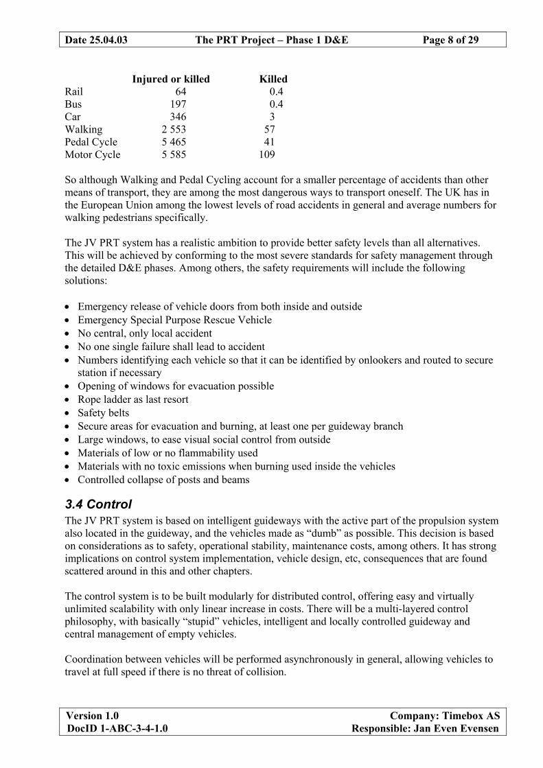
To be able to move in a mesh network, vehicles must be able to choose between a left or right track, and the track it is moving on must be able to merge with another track. In the first instant, the vehicle must have some kind of reliable switching mechanism. In the latter instant, the system as such must be able to ensure that no two vehicles will meet at the point of track merger. These technologies are critical to safe system operation. The vehicle will continuously transmit its identity to sensors in the guideway which in return will transmit the position along the track to the vehicle, allowing the vehicle to preposition the in-vehicle switch to catch right or left guiderail when entering the next guideway splitting junction. At merging junctions, a special merge controller at that guideway section will assign priority to the vehicle coming from the most congested track. Since the JV PRT system has intelligent guideways, it will be the guideway section that the vehicle is travelling on, which will know where the vehicle is destined. It will thus be the guideway segment before a splitting junction which transmits to the vehicle in which position the vehicle should set the in-vehicle switch in order for the vehicle to go to right or left in the junction. For increased robustness, it will be considerer in the next phase of this project to also let the vehicle carry with it its destination, and then receive positional information from the guideway. If a passenger needs to change destination, there will be a “Stop at next station” button.
3.4.1 Safe merging junctions At merging junctions, two tracks come together to one track. Vehicles on the most congested line or the vehicle closest to the junction will be given priority. Such automatic and safe coordination requires a local point-synchronous control system at the merging guideway junctions, in addition to other fail-safe mechanisms.
3.4.2 Switching right or left in a splitting junction A most fundamental property of a PRT system is the inherent ability for vehicles to travel with extremely short headways. In the beginning, distance between vehicles on the guideway will be in the order of 2.5 seconds, translating to 30 m. As software, hardware and procedures become robust, considerable shorter headways are envisaged, in order to increase system capacity. (In car traffic on highways, headways in rush hours are often below 1.2 seconds at 80 km/h – with much less failsafe human drivers.) Vehicles will need to have the ability to turn right or left at splitting junctions in order to navigate the PRT network. The only way to make switching of vehicles travelling close together possible in a safe way is using passive rails and guideways and let the active function to perform the physical motion required for switching reside inside the vehicle. The guideway design will allow the normal rails to be used for securing sideways stability as well as to be used as guiderails before each splitting junctions. The guide wheels in the vehicle will latch onto the outside of either the right or left guiderail and thus pull the whole vehicle in this direction. This design is developed for the JV PRT project by common efforts of the project team, and will be IP protected.
Date 25.04.03 The PRT Project – Phase 1 D&E Page 10 of 29
Version 1.0 Company: Timebox AS DocID 1-ABC-3-4-1.0 Responsible: Jan Even Evensen
3.5 Capacity of a PRT Network The capacity of a PRT line is very important for achieving high overall system capacities. At first, the JV PRT system will be designed for normal operation at 45 km/hour. Hovever, in the future there might be a need for higher speeds at sertain long and heavily trafficed guideway segments. The JV PRT technology will be able to accomodate such needs, since the propulsion resides in the guideway and not in the vehicle. High-presision guideway sections with stronger propulsion mechanisms will thus enable higher speeds at selected guideway sections. Even though the normal operating speed can seem low, since the vehicles travel non-stop, the average speed in the city will be significantly higher than for all alternative transportation systems and cars. The higher effective speed provides the passengers with a shorter travel time, in an air-conditioned and stress-free environment. In peak hours, the use of dedicated station doors towards specific destinations will be used in order to increase average ridership numbers, up to a maximum of 4 passengers per vehicle. It is assumed during peak hours that only loaded – though not fully loaded - vehicles will be travelling from stations in the direction that have the highest demand, and that empty vehicles will travel back to pick up more passengers. This is beacuse during peak hours, traffic will be assymetrical, with most people going in generally the same direction, to or from work. If peak traffic is symmetrical, it will be profitable to add extra system capacity. At peak hours, line capacity will therefore also be used closer to its theoretical maximum. At off-peak hours, there will always be free vehicles available, and there is sufficient capacity by definition. The example shows maximum traffic flow on one PRT line with all “time-slots” filled and vehicles filled to maximum capacity. One hundred percent of maximum capacity will never be utilised, but must be designed for.
Date 25.04.03 The PRT Project – Phase 1 D&E Page 11 of 29
Version 1.0 Company: Timebox AS DocID 1-ABC-3-4-1.0 Responsible: Jan Even Evensen
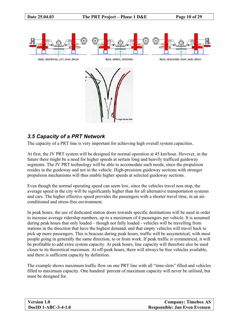
The following calculation illustrates theoretical maximum PRT line capacity:
Maximum Capacity of a PRT line
Distance between support posts 18 meters Distance between vehicles 30 meters Speed 45 km/hour Speed 12.5 meters/second Time between vehicles 2.4 seconds Theoretical maximum line capacity 1 500 Vehicles/hour Theoretical maximum line capacity, 4 passengers/vehicle
6 000 Passengers/hour
Average utilisation of vehicles might not be more than 2 people, as a conservative estimate even for peak hours. It will be one of the key tasks for the operating company to introduse measures to increase this number. When comparing the capacity of a LRT line with a PRT network, one must bare in mind the difference between a line and a network. LRT lines are like motorways that carry all traffic to a certain area. A line in a PRT system will to a large degree carry traffic to that particular branch of the network, and vehicles will automatically be routed through the network in the (close to) most efficient way. There is much R&D going on regarding Intelligent Traffic Systems, and much of the work is targeted towards directing automobile drivers in certain directions. Such ITS systems have to cater for an immense range of parameters to work efficiently, they seldom know the destination of the driver, and the driver still has the choice of ignoring the advice. A PRT system is a much more limited universe of options, and can therefore be made to optimise traffic flow at the system level. It will – properly set up - automatically exploit the total resources of the network to satisfy the demand in an optimal way.
3.6 Guideways and propulsion The guideway consist of supporting posts and runway beams. The guideway shall support the vehicles, but it must also be able to satisfactory withstand wind, rain, snow, ice, earthquakes, impacts from ground vehicles, etc. The guideway will have an open mechanical structure, which will strongly limit the accumulation of rain, snow, ice and leaves by allowing them to fall through. Heat from the LIMs will also reduce accumulation of snow and ice. What might remain will be reduced by a small mechanical “plough” or brush in front of the front wheels. Further, an open structure guideway will be less exposed to forces of wind. Vehicles having slow speed compared to cars should allow birds to fly out of harms way. The guideway can run directly on ground level in tunnels and buildings and elevated and protected from people, animals and climatic conditions outdoors. Elevated, the guideway will be supported by columns 18-20 m apart, constructed in such a way that a large number of physical appearances are possible.
Date 25.04.03 The PRT Project – Phase 1 D&E Page 12 of 29
Version 1.0 Company: Timebox AS DocID 1-ABC-3-4-1.0 Responsible: Jan Even Evensen
Also, one can envision a family of guideways, such as more affordable low traffic - long headway versions, high-capacity ones and versions for low or high speeds. The installation of temporary lines will also be possible. Guideways will be designed for specific speeds, with matching grades at curves, for maximum passenger comfort. For higher speeds, there would be a need for more powerful LIM motors in the guideway and tighter mechanical tolerances. The posts can be made from many different materials and designs. Here, aesthetics will be important, but also structural considerations. Materials such as steel, concrete, wood, composites and aluminium must be evaluated.
The beams can likewise be made from materials such as concrete, steel, laminated wood and aluminium. Rigidity in combination with vehicle suspension will determine rider comfort. It will be advantageous if it is possible to give the vehicles a movement pattern that reminds the passengers of other known means of utility transport. Familiarity will decrease fear and increase ridership. Acceptable levels of lateral, vertical and sideways acceleration will have to be determined. Reducing jerk has considerable consequences for the modularisation of the tracks, as “rollercoaster like”, rough changes in curve radius cannot be accepted.
Date 25.04.03 The PRT Project – Phase 1 D&E Page 13 of 29
Version 1.0 Company: Timebox AS DocID 1-ABC-3-4-1.0 Responsible: Jan Even Evensen
The PRT system may be installed in tunnels
3.6.1 Linear Electric Motors Propulsion of vehicles will be performed through Linear Motors (LIM) every three meters along the guideway, which control vehicle speed through reacting with a copper plate under the vehicle. This propulsion arrangement requires no moving parts, and natural operating heat dissipation from the (steel covered) LIMs will prevent accumulation of snow and ice. The LIM is a well proven technology ideally suited to PRT application. Motion is independent of wheel friction making the LIM ideal in adverse environments. In the JV PRT system the LIM is fixed to the guideway and the reaction plate is fixed to the vehicle. Environmental protection is provided with a non-magnetic stainless steel enclosure for the LIM.
Date 25.04.03 The PRT Project – Phase 1 D&E Page 14 of 29
Version 1.0 Company: Timebox AS DocID 1-ABC-3-4-1.0 Responsible: Jan Even Evensen
As the drawings show the LIM is essentially a circular motor opened out flat. The wound stator, which is the part usually known as the LIM, consists of a conventional 3 phase winding in a laminated iron core. When energised from a 3 phase AC supply a travelling magnetic field is produced which sweeps across the flat motor face. Direction is reversed simply by swapping two incoming supply phases.
“ - take a conventional squirrel cage induction motor .….. - open it out flat .…. - smooth the rotor bars into a conductor sheet …... - apply AC power .…... and you have a LIM The ‘reaction plate’ conductor sheet is the equivalent of the rotor. This is usually a flat conductor sheet of aluminium or copper, backed by steel. Currents induced in the reaction plate by the stator’s travelling field create a secondary magnetic field. It is the reaction of these two fields which produces the linear thrust. Highest propulsion power will be required for breaking vehicles before stations on side lines and for propelling them away after stations. On the main line, power will be required to propel vehicles at operating speed of 12.5 m/s up steepest gradients against strong winds. Since the control system operates generally in an asynchronous mode, a slower maximum speed can be tolerated at extremely windy days. Accepting a mild deviation from perfect service levels at all times, one can design the system for operating at full speed for example only 99.9% of the time, offering significant cost benefits. Some main features of having LIMs in the guideway are: • No propulsion from wheels, removing the requirement for friction between wheel and surface.
Electromagnetic propulsion enables therefore safe operation in conditions of snow and ice and efficient running up and down steep hills and grades.
• No moving parts for propulsion, reducing maintenance • No complex power transfer to vehicle The JV PRT tracks will be reversible for allowing backing of vehicles and potentially reversing travel direction at later time. No extra cost is envisaged for allowing reversibility of guideways.
Date 25.04.03 The PRT Project – Phase 1 D&E Page 15 of 29
Version 1.0 Company: Timebox AS DocID 1-ABC-3-4-1.0 Responsible: Jan Even Evensen
3.7 Vehicles The vehicles are designed to be as light and cheap in manufacturing and operation as possible. In order for the JV PRT vehicles to be relatively light and cheap, they need to be computationally as “stupid” as possible and be mechanically little complex. To achieve such vehicle properties, computational power, precision mechanics and propulsion are to the extent possible located in the guideway. Target vehicle weight is less than 600 kg with a freight capacity of another 600 kg. Vehicles are designed for having as low a centre of gravity as possible, for maximum stability.
Design studies (i.e. not suggestions as to shape of vehicle top)
Vehicles will have four seated passengers, two facing forward and two facing backwards. Typical net load will be in the order of 600 kg. Each vehicle will have two “plug doors” on each side, which will open synchronously with station doors. Having doors at both sides of the vehicles at will allow having off line stations at both sides of the main track. Doors on both sides of the vehicle will also be make it possible to have build high-capacity stations where passengers exit to one side and enters from the other.
Date 25.04.03 The PRT Project – Phase 1 D&E Page 16 of 29
Version 1.0 Company: Timebox AS DocID 1-ABC-3-4-1.0 Responsible: Jan Even Evensen
The vehicle must be comfortable for riders and be easy to evacuate in a case of emergency. Emergency exit will be provided, either for evacuation to another vehicle, or for the transferring of passengers to street level. Comfort levels can be high without increasing weight too much, and standing passengers will not be allowed of safety reasons. Suspension is critical to passenger comfort. Required complexity of suspension will have to be determined as a trade-off towards structural rigidity of beams. Silent propulsion will allow integrated music systems, and silent air conditioning will be a standard feature.
Strong headwinds will potentially exert strong forces towards the vehicle, necessitating an aerodynamic design in order to minimise dimensioning of LIMs. LIMs should therefore be dimensioned according to local conditions. Aerodynamic design can be combined with added collision protection mechanisms.
Date 25.04.03 The PRT Project – Phase 1 D&E Page 17 of 29
Version 1.0 Company: Timebox AS DocID 1-ABC-3-4-1.0 Responsible: Jan Even Evensen
Automatic freight of goods will be possible without the removal of seats. Further, the vehicles will be designed for automatic cleaning and maintenance. The vehicle is physically locked to the guideway at all times using a combination of rails and wheels, where some are used in normal operation and some are utilised only in emergency situations. Emergency breaking is based on calliper brakes with tungsten carbide tipped pads, which bite through snow or ice. Therefore emergency breaking is not dependent on friction between wheels and guideway, and is independent of snow or ice. The brakes will be triggered if there is a dangerous power failure, or if a hindrance is detected along the guideway. Guide wheels and calliper brakes can be manually turned into positions that free the vehicle from the track. Hence, a vehicle can, if circumstances demand, be lifted off the track.
Power to in-vehicle operations such as switch mechanisms, internal and external lighting, com-munication and computing equipment and climate control will amount to approximately 1 kW, and will be transferred mechanically to the vehicle through the wheels to be picked up by a power generator mounted on one wheel axle. The vehicles are not depending on electricity supply to the vehicles for any critical function, as propulsion and safety systems are mainly installed in guideways, and the vehicles are not ”in command”: The entire fleet management is based on intelligent guideways, not intelligent vehicles. Vehicles can be propelled along the track even if no electrical functions remain on board. But there is a need for a battery in the vehicle for operating the switching mechanism, maintain computer and audio communication and for preventing the emergency breaks from releasing in situations where this is not required. In extremely dense cities, it is probable that special emergency type vehicles will be developed and operated for agencies such as the police, fire brigades and ambulance services.
Date 25.04.03 The PRT Project – Phase 1 D&E Page 18 of 29
Version 1.0 Company: Timebox AS DocID 1-ABC-3-4-1.0 Responsible: Jan Even Evensen
3.8 Stations For a PRT system to be attractive there must be at least one station within walking distance from where people work, live or spend their spare time. Stations in the JV PRT system are always off the main line, on a special side line for retardation, waiting, stop and acceleration, in order for vehicles on the main line to travel uninterrupted by vehicles departing or entering. Offline stations are what allow PRT to offer non-stop transportation, low energy consumption and robustness towards large-scale system failure. With stations mostly being integrated into existing or new buildings, the main cost of adding a station is cost of the off-line guideway section itself, connecting the station to the main line. In numbers, adding an off-line new station to an existing PRT system will cost in the order of NOK 2-5 million, a significantly higher cost than for a bus or tram stop, but still more affordable than a Train or LRT station. Stations need to accommodate blind people with sticks or dogs, hearing impaired, handicapped using wheelchairs, children and elderly travelling alone, by a combination of simple station layout and access combined with simple and effective audio-visual and tactile/sensory information technologies. At stations there will be a mechanism determining the weight of vehicles for ensuring transport with acceptable vehicle loadings or determining if a vehicle is empty. Doors providing access to vehicles will open automatically using normal “supermarket” type infrared sensors for determining approaching people. If snow on the vehicles becomes a problem, special “brush gates” may be installed at stations for removing snow. With wide vehicle doors and the four people most often either exiting or at a different time of day only entering, average stopping time will be short.
Date 25.04.03 The PRT Project – Phase 1 D&E Page 19 of 29
Version 1.0 Company: Timebox AS DocID 1-ABC-3-4-1.0 Responsible: Jan Even Evensen
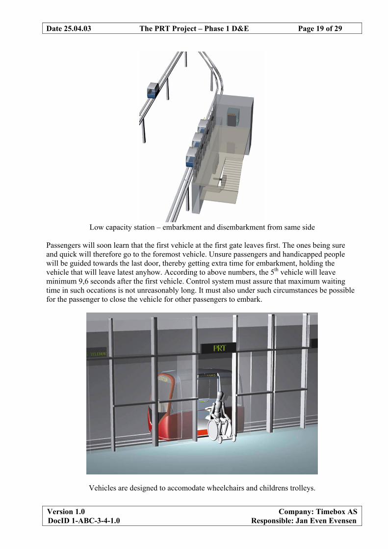
Low capacity station – embarkment and disembarkment from same side
Passengers will soon learn that the first vehicle at the first gate leaves first. The ones being sure and quick will therefore go to the foremost vehicle. Unsure passengers and handicapped people will be guided towards the last door, thereby getting extra time for embarkment, holding the vehicle that will leave latest anyhow. According to above numbers, the 5th vehicle will leave minimum 9,6 seconds after the first vehicle. Control system must assure that maximum waiting time in such occations is not unreasonably long. It must also under such circumstances be possible for the passenger to close the vehicle for other passengers to embark.
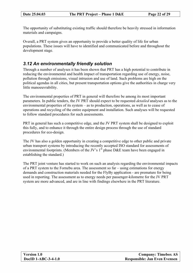
Vehicles are designed to accomodate wheelchairs and childrens trolleys.
Date 25.04.03 The PRT Project – Phase 1 D&E Page 20 of 29
Version 1.0 Company: Timebox AS DocID 1-ABC-3-4-1.0 Responsible: Jan Even Evensen
A Light Rail Transit (LRT) station can have a larger capacity, but the lower cost of PRT stations allows more stations for the convenience of passengers. Further, the capacity of a PRT station can be designed to have capacity according to expected demand. By employing multi-door stations for simultaneous embarking and disembarking from one or more vehicles, capacity can be further increased. Simulations (Andreasson 1997) provide the following station capacity numbers, depending on number of number of station platform positions. This theory will be tested in the next phase of this project at the test track, in order to design stations with as high passenger capacity as possible.
0100200300400500600700800900
0 2 4 6 8
Platform positions
Pas
seng
er c
apac
ity
Ticketing may be done in a number of ways, and must through an open interface accommodate special requirements of local authorities. As ticketing is considered non-critical, it has not been further studied in this phase of D&E. However, it is clear that there must be a system of admission control combined to the ticketing and the fleet management to provide relevant information to the overall control system. Hence, the ticketing system must also be interfaced properly to the control system of the PRT application.
3.9 Installation and expansion Initial installation will be significantly less intrusive than for alternative means of transportation. Columns, guideway support structures and the guideway itself will be modularly pre-fabricated for effective installation on-site in a matter of weeks and months rather than years. Due to low weight, columns can have simple foundations, allowing even temporary lines. Reduction of jerk puts certain limits as to which extent guideway modules may be standard pre-fabricated, or must be produced according to design for the specific application. When a PRT system is initially opened at a new site, it will probably make sense to have people manning all stations as hosts and “personal trainers” until trained passengers will assume this responsibility towards others.
Date 25.04.03 The PRT Project – Phase 1 D&E Page 21 of 29
Version 1.0 Company: Timebox AS DocID 1-ABC-3-4-1.0 Responsible: Jan Even Evensen
At corporate sites, there would probably be an initial phase whereby only employees of selected corporations could use the system, in order to systematically get feedback on how passengers perceive the system for fine-tuning functionality and means and types of information before official public launch.
3.10 Operation, Service and maintenance The basic philosophy will be design for extensive automation of service and maintenance. Operational costs can be low because of low price of vehicles, design for automatic operations and maintenance, low energy consumption and that people do not have access to the outside of the vehicles to perform vandalism. Safety requirements will though impose manned control centres. Automatic cleaning stations for exteriors of vehicles will be installed at depots, and vehicle interior will be designed for highly automated cleaning. In the FlyBy case, each vehicle will travel in the order of 100.000 km per year. Regular control of wheels and bearings will be essential. With regards to wheel material, a compromise will need to be defined between wear, maintenance and noise. Noise levels for the JV PRT design have not been studied. They may be adjusted in various ways, e.g. with fillings in the steel rails, and by the choice of guideway support beam materials (e.g. concrete and wood). As organisational guidelines, there would be a culture promoting safety and continuous improvement. The operating company should be as small as possible, hiring only highly qualified employees, utilising suppliers to a large degree.
3.11 Social Impact and Quality of Life The primary negative impact of a PRT system will be visual, the system both requiring having structures in the middle of the street that did not use to be there and also that the passengers will be able to see through windows, some of which used to be private. There will also be new sounds and some new noise. Such problems have to be paid particular attention, as they will easily come high on political agendas. The problems have to be solved by good area planning, screens, choice of suitable materials, and by not overselling PRT for inappropriate urban environments. Apart from the challenges mentioned above, most impacts will be of a positive nature: There will be less time spent in traffic, less energy consumption per passenger-km, less pollution and less noise. A PRT system will remove traffic loads from other means of transport, and reduce the occurrence of queue formation. Further, the transport of goods through PRT will significantly reduce street congestion. Not the least, there will be a significantly less number of accidents, compared to present transportation modes causing much property damage, personal injury and deaths. However, this only happens if politicians and/or urban governments are helped to use the PRT system to substitute existing traffic. It the PRT system just creates added mobility, the effect is nil.
Date 25.04.03 The PRT Project – Phase 1 D&E Page 22 of 29
Version 1.0 Company: Timebox AS DocID 1-ABC-3-4-1.0 Responsible: Jan Even Evensen
The opportunity of substituting existing traffic should therefore be heavily stressed in information materials and campaigns. Overall, a PRT system gives an opportunity to provide a better quality of life for urban populations. These issues will have to identified and communicated before and throughout the development stage.
3.12 An environmentally friendly solution Through a number of analyses it has been shown that PRT has a high potential to contribute in reducing the environmental and health impact of transportation regarding use of energy, noise, pollution through emissions, visual intrusion and use of land. Such problems are high on the political agendas in all cities, but present transportation options give the authorities in charge very little manoeuvrability. The environmental properties of PRT in general will therefore be among its most important parameters. In public tenders, the JV PRT should expect to be requested detailed analyses as to the environmental properties of its system – as to production, operations, as well as to cease of operations and recycling of the entire equipment and installation. Such analyses will be requested to follow standard procedures for such assessments. PRT in general has such a competitive edge, and the JV PRT system shall be designed to exploit this fully, and to enhance it through the entire design process through the use of standard procedures for eco-design. The JV has also a golden opportunity in creating a competitive edge to other public and private urban transport systems by introducing the recently accepted ISO standard for assessments of environmental footprints. (Members of the JV’s 1st phase D&E team have been engaged in establishing the standard.) The PRT joint venture has started to work on such an analysis regarding the environmental impacts of a PRT system to the Fornebu area. The assessment so far – using estimations for energy demands and construction materials needed for the FlyBy application - are premature for being used in reporting. The assessment as to energy needs per passenger-kilometre for the JV PRT system are more advanced, and are in line with findings elsewhere in the PRT literature.
Date 25.04.03 The PRT Project – Phase 1 D&E Page 23 of 29
Version 1.0 Company: Timebox AS DocID 1-ABC-3-4-1.0 Responsible: Jan Even Evensen
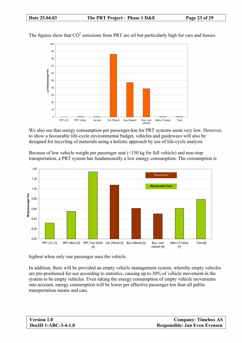
The figures show that CO2 emissions from PRT are nil but particularly high for cars and busses.
We also see that energy consumption per passenger-km for PRT systems seem very low. However, to show a favourable life-cycle environmental budget, vehicles and guideways will also be designed for recycling of materials using a holistic approach by use of life-cycle analysis Because of low vehicle weight per passenger seat (<150 kg for full vehicle) and non-stop transportation, a PRT system has fundamentally a low energy consumption. The consumption is
highest when only one passenger uses the vehicle. In addition, there will be provided an empty vehicle management system, whereby empty vehicles are pre-positioned for use according to statistics, causing up to 30% of vehicle movement in the system to be empty vehicles. Even taking the energy consumption of empty vehicle movements into account, energy consumption will be lower per effective passenger-km than all public transportation means and cars.
0
10
20
30
40
50
60
70
80
90
100
PRT (JV) PRT (Ultra) Car (el) Car (Petrol) Bus (Diesel) Bus, rush(diesel)
Metro (T-bane) Tram
g C
O2/
pass
enge
r*km
0,00
0,20
0,40
0,60
0,80
1,00
1,20
1,40
PRT (JV) [1] PRT (Ultra) [2] PRT (Taxi 2000)[3]
Car (Petrol) [4] Bus (Diesel) [5] Bus, rush(diesel) [6]
Metro (T-bane)[7]
Tram [8]
MJ/
pass
enge
r*km
Fossil fuel
Renewable fuel
Date 25.04.03 The PRT Project – Phase 1 D&E Page 24 of 29
Version 1.0 Company: Timebox AS DocID 1-ABC-3-4-1.0 Responsible: Jan Even Evensen
3.13 Concluding remarks to Joint Venture PRT Technology This paper has aimed to demonstrate that all major technological issues have been treated in detail, and can be solved using off-the-shelf technologies and methodologies. In addition, we have developed design solutions and criteria that will give the JV PRT solution a favourable competitive edge to all known solutions for urban transport – not in all, but in many circumstances common in cities as well as in other large areas. The technological risk in allocating funds towards developing a full-scale system therefore seems moderate. However, during the development project, there will be a large number of design issues that will need to be solved in an efficient and elegant way, also adding to the value of Intellectual property.
Date 25.04.03 The PRT Project – Phase 1 D&E Page 25 of 29
Version 1.0 Company: Timebox AS DocID 1-ABC-3-4-1.0 Responsible: Jan Even Evensen
4 Appendix: PRT Project Design Parameters
4.1 Control
PRT Project Design Parameters
Release 1.1 030403 Parameters Unit 1st stage
Test PRT 1st stage
Fornebu PRT Status
Control
Platooning of vehicles without people
no no Locked
Platooning of vehicles with people
no no Locked
Empty Vehicles Management
no yes Locked
Guideway Controlled Vehicle Motion
yes yes Locked
Zone Control Hierarchy
yes yes Locked
Local Synchronous Control
yes yes Locked
Local handling of emergency resolution
yes yes Locked
Variable speed on main line
yes yes Locked
Headway
T (sec) 2,00 3,5 Locked
Remotely activated emergency brake
yes yes Locked
Date 25.04.03 The PRT Project – Phase 1 D&E Page 26 of 29
Version 1.0 Company: Timebox AS DocID 1-ABC-3-4-1.0 Responsible: Jan Even Evensen
4.2 Guideway
PRT Project Design Parameters
Release 1.1 030403 Parameters Unit 1st stage
Test PRT 1st stage
Fornebu PRT Status
Guideway
In track switch guiderails
yes yes Locked
In track LIMs
yes yes Locked
Reversible Track Direction
no yes Locked
LIM Participation in emergency breaking
no no Locked
Permanent magnets in retardation sections
yes yes Locked
Speed "Full Speed Line" V (m/s)
12,5 12,5 Locked
Ramp gradient velocity Vu (m/s)
10 10 Locked
Max Acceleration/Retardation a (m/s2)
3 2,5 Locked
Changes in forward acceleration - jerk C (m/s3)
3 2,5 Locked
Non compensated side acceleration aq (m/s2)
2,5 1,50 Locked
Emergency Retardation a (m/s2)
8 5 Locked
Automatic Vehicle Protection System yes yes Locked
"Over height" - Camber u (%)
10 <10 Locked
Free line speed 10m/sec
>30 >40 Locked
Side acceleration 1.5m/sec2 Rh (m)
67 67
Side acceleration 2.5m/sec2 Rh (m)
40 40
Free line speed 12.5m/sec2
Side acceleration 1.5m/sec2 Rh (m)
104 104
Side acceleration 2.5m/sec2 Rh (m)
63 63
Turning sections and depots (Reduced speed) Rh (m)
> 6 > 6 Locked
Vertical radius Rv (m)
> 100 > 200 Locked
Climb s (%)
< 10 < 5 Locked
Length vertical curve Lv (m)
10 10 Open
Free height over road / rails H (m)
- 4,75 Locked
Date 25.04.03 The PRT Project – Phase 1 D&E Page 27 of 29
Version 1.0 Company: Timebox AS DocID 1-ABC-3-4-1.0 Responsible: Jan Even Evensen
Free height other areas H (m)
- 2,75 Locked
Minimum Passing Distance between two vehicles D (m)
0,3 0,3 Locked
Distance between rails Lv (mM)
625 625 Locked
Length of guideway element Lv (m)
<20 <20 Locked
Non-combustible materials
yes yes Locked
4.3 Stations
PRT Project Design Parameters
Release 1.1 030403 Parameters Unit 1st stage
Test PRT 1st stage
Fornebu PRT Status
Stations
Station locks vehicle at gate
no issue no issue
Vehicle weight measured at gate before travel
yes yes Locked
Station unlocks/locks & opens/closes vehicle doors
no no Locked
Linear stations on straight off-line lines
yes yes Locked
Closed to track by station sliding doors
yes yes Locked
Length of "Full Speed Station"
L (m) 88 88 Open
Min Length of "Slow Speed Station"
L (m) Open
Min Spilt/Merge speed "Slow Speed Station" V (m/s)
Open
Non-combustible materials
yes yes Locked
Date 25.04.03 The PRT Project – Phase 1 D&E Page 28 of 29
Version 1.0 Company: Timebox AS DocID 1-ABC-3-4-1.0 Responsible: Jan Even Evensen
4.4 Vehicles
PRT Project Design Parameters
Release 1.1 030403 Parameters Unit 1st stage
Test PRT 1st stage
Fornebu PRT Status
Vehicles
No. of passengers
4 4 Locked
Provision for wheel chairs
yes yes Locked
Provision for 800x1200 Euro Pallets
yes yes Locked
Active mechanical switch
yes yes Locked
Mechanical emergency brakes
yes yes Locked
Manual in-vehicle emergency brake activation
yes yes Locked
Manual on-vehicle release of emergency brake
yes yes Locked
Separate parking brakes
no no Locked
Seat belts
no yes Locked
Doors on both sides of vehicle
no yes Locked
Vehicle doors opened and locked by station
no no Locked
Vehicle plug doors
yes yes Locked
Bi-parting doors
yes yes Locked
Mechanical in-vehicle door release
yes yes Locked
Door width
mm 900 900 Locked
Door opening/closing time
<3 <3 Open
Anti Collision System (Radar based) yes yes Locked
In-vehicle LIMs for propulsion
No No Locked
In-vehicle LIMs for power transfer
No Maybe Open
Wheel-generated Power (heating/airc./controls)
Yes Maybe Locked
In-vehicle battery-based Power (heating/airc./controls)
yes yes Locked
On board power (heating/airc./controls)
P (kW) 1 1 Locked
Date 25.04.03 The PRT Project – Phase 1 D&E Page 29 of 29
Version 1.0 Company: Timebox AS DocID 1-ABC-3-4-1.0 Responsible: Jan Even Evensen