52

Legal informationThis manual is protected by copyright and all reproduction and further distribution without written authorization from Elektron Music Machines MAV AB is strictly prohibited. The content of this manual is for informational use only, is subject to change without notice and should not be read as a commitment by Elektron Music Machines MAV AB. El-ektron Music Machines MAV AB holds no responsibility or liability for any errors or inaccuracies that may appear in this manual.
Elektron Music Machines MAV AB or its Licensors, holds all the rights, including intellectual property rights, consisting of but not limited to, patents, copyrights, designs, trademarks and trade secrets to and in relation to the Overbridge Suite and all its software and hardware components, including the Analog Keys, Analog Four and Analog Rytm and their corresponding Plugins, as well as any future Overbridge Applications and Devices.
INTRODUCTION..............................................................................................................1
THE OVERBRIDGE SUITE .............................................................................................2COMPATIBLE ELEKTRON INSTRUMENTS.......................................................................................... 2SOFTWARE COMPONENTS................................................................................................................. 2FEATURES............................................................................................................................................. 2
CONTROL PANEL LAYOUT ...........................................................................................3OVERBRIDGE CONTROL PANEL......................................................................................................... 3SETTING UP AND STARTING YOUR OVERBRIDGE DEVICE ............................................................ 4
QUICK START .................................................................................................................5FIVE-STEP WALKTHROUGH ................................................................................................................ 5
LEARN MORE ABOUT YOUR OVERBRIDGE DEVICE................................................................... 5LEARN MORE ABOUT YOUR DAW................................................................................................. 5
INSTALLING OVERBRIDGE...........................................................................................6SYSTEM REQUIREMENTS ................................................................................................................... 6INSTALLING ........................................................................................................................................... 6ACTIVATE OVERBRIDGE MODE .......................................................................................................... 6WINDOWS.............................................................................................................................................. 6
VST LOCATIONS .............................................................................................................................. 7UNINSTALLING (WINDOWS) ........................................................................................................... 7
MAC OS X .............................................................................................................................................. 7SANDBOXED HOSTS....................................................................................................................... 7UNINSTALLING (MAC OS X)............................................................................................................ 7
USB AND BANDWIDTH..................................................................................................8LIMITATIONS.......................................................................................................................................... 8
AUDIO INTERFACE ........................................................................................................9ASIO CHANNEL TABLE....................................................................................................................... 10
ANALOG KEYS / FOUR CHANNELS ............................................................................................. 10ANALOG RYTM CHANNELS .......................................................................................................... 10
THE CONTROL PANEL ................................................................................................ 11MATCHING SOFTWARE PROTOCOLS ...............................................................................................11AUDIO I/O............................................................................................................................................. 12
INTERFACE WITH THE RYTM DEVICE......................................................................................... 12INTERFACE WITH THE KEYS/FOUR DEVICE .............................................................................. 14
GENERAL PERFORMANCE SETTINGS............................................................................................. 16GENERAL PLUGIN PERFORMANCE SETTINGS ......................................................................... 16SOUND CARD AND DRIVER PERFORMANCE SETTINGS ......................................................... 16
MULTIPLE SOUND CARDS................................................................................................................. 16WINDOWS....................................................................................................................................... 16MAC................................................................................................................................................. 16
CONNECTION STATUS INDICATOR................................................................................................... 17
THE PLUGINS ...............................................................................................................18PLUGIN GENERAL CONTROLS ......................................................................................................... 18
CONTROL ELEMENTS AND INDICATORS ................................................................................... 19MIDI CONTROL............................................................................................................................... 22PARAMETER AUTOMATION .......................................................................................................... 22MACHINE STATE TOTAL RECALL................................................................................................. 23QUICK ASSIGN............................................................................................................................... 24
ANALOG KEYS / FOUR PLUGIN OVERVIEW .................................................................................... 26KIT EDITOR..................................................................................................................................... 26SOUND BROWSER ........................................................................................................................ 27
1 of 2

ANALOG RYTM PLUGIN OVERVIEW ................................................................................................. 28KIT EDITOR..................................................................................................................................... 28SAMPLE SECTION ......................................................................................................................... 29SOUND BROWSER ........................................................................................................................ 30
INDIVIDUAL OUTPUTS........................................................................................................................ 31MULTIPLE OUTPUTS........................................................................................................................... 31SIDECHAIN INPUTS ROUTING........................................................................................................... 31
SEQUENCING WITH THE DIGITAL AUDIO WORKSTATION ..................................... 32SYNCING THE ELEKTRON SEQUENCER ......................................................................................... 32PATTERN CHANGE ............................................................................................................................. 32
CREDITS AND CONTACT INFORMATION .................................................................. 33CREDITS .............................................................................................................................................. 33
OVERBRIDGE DESIGN AND DEVELOPMENT ............................................................................. 33ADDITIONAL DESIGN..................................................................................................................... 33TESTING ......................................................................................................................................... 33MANUAL.......................................................................................................................................... 33
CONTACT INFORMATION ................................................................................................................... 33ELEKTRON WEBSITE .................................................................................................................... 33OFFICE ADDRESS ......................................................................................................................... 33TELEPHONE ................................................................................................................................... 33
APPENDIX A: MEDIA RESOURCES
APPENDIX B: SETUP EXAMPLE
INDEX
2 of 2

INTRODUCTION
INTRODUCTIONThank you for downloading the Overbridge Software Suite. Overbridge is a family of components designed to make music using both hardware and software as convenient, fun and hassle-free as possible.
Overbridge offers a multiple device multitrack control component, as well as software plugin components cus-tomized for the Analog Keys, Analog Four and Analog Rytm so that they may be synced, edited, sequenced and recorded with your Digital Audio Workstation.
We are convinced you’ll find making music using Overbridge an awesome experience. Enjoy!
The following symbols are used throughout the manual:
Information that you must pay attention to.
A tip that will make it easier for you to interact with Overbridge.
This symbol shows a nice ear. Be nice to your ears.
1
THE OVERBRIDGE SUITE
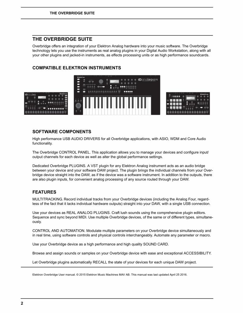
THE OVERBRIDGE SUITEOverbridge offers an integration of your Elektron Analog hardware into your music software. The Overbridge technology lets you use the instruments as real analog plugins in your Digital Audio Workstation, along with all your other plugins and jacked-in instruments, as effects processing units or as high performance soundcards.
COMPATIBLE ELEKTRON INSTRUMENTS
SOFTWARE COMPONENTS
High performance USB AUDIO DRIVERS for all Overbridge applications, with ASIO, WDM and Core Audio functionality.
The Overbridge CONTROL PANEL. This application allows you to manage your devices and configure input/output channels for each device as well as alter the global performance settings.
Dedicated Overbridge PLUGINS. A VST plugin for any Elektron Analog instrument acts as an audio bridge between your device and your software DAW project. The plugin brings the individual channels from your Over-bridge device straight into the DAW, as if the device was a software instrument. In addition to the outputs, there are also plugin inputs, for convenient analog processing of any source routed through your DAW.
FEATURES
MULTITRACKING. Record individual tracks from your Overbridge devices (including the Analog Four, regard-less of the fact that it lacks individual hardware outputs) straight into your DAW, with a single USB connection.
Use your devices as REAL ANALOG PLUGINS. Craft lush sounds using the comprehensive plugin editors. Sequence and sync beyond MIDI. Use multiple Overbridge devices, of the same or of different types, simultane-ously.
CONTROL AND AUTOMATION. Modulate multiple parameters on your Overbridge device simultaneously and in real time, using software controls and physical controls interchangeably. Automate any parameter or macro.
Use your Overbridge device as a high performance and high quality SOUND CARD.
Browse and assign sounds or samples on your Overbridge device with ease and exceptional ACCESSIBILITY.
Let Overbridge plugins automatically RECALL the state of your devices for each unique DAW project.
Elektron Overbridge User manual. © 2015 Elektron Music Machines MAV AB. This manual was last updated April 25 2016.
MasterVolume
- +
2

CONTROL PANEL LAYOUT
CONTROL PANEL LAYOUT
OVERBRIDGE CONTROL PANEL
The Overbridge Control Panel.
1. Visual representation of your Overbridge devices. A green dot means the device is connected and active. Hollow dot means the device is inactive (switched off or disconnected). Red dot means bad communication.
2. Gear icon: show/hide general plugin buffer size and user interface settings.
3. Wrench icon: show/hide driver & sound card functionality settings.
4. Output channel configuration. Activate/deactivate an audio channel into your Overbridge device by clicking on the toggle button below it. Green means the channel is active, gray means it's not.
5. Discard / Apply buttons. Whenever a change is made you need to press the Apply button before the new settings come into effect. Pressing Discard resets the settings to the last state that was applied.
6. USB bandwidth meter. Shows the bandwidth used by the current channel configuration. The maximum bandwidth capacity corresponds to 8 channels per direction (16-bit) or 6 channels per direction (24-bit) for each connected Overbridge device.
7. Information box. Hover over any item on the Control Panel with the mouse pointer to get a brief description of it.
8. Input channel configuration. Activate/deactivate an audio channel from your Overbridge device by clicking on the toggle button directly below it. Green means the channel is active, gray means it's not.
9. VU-meters. Show channel activity and signal strength.
10. Bit depth selector. Set the Input and Output Channels to either 16-bit or 24-bit.
11. Device OS, Overbridge Protocol, Overbridge version and driver currently installed as well as an indication if the Sound Card functionality is enabled or not for the device in view.
12. The name of your Overbridge device. Double click on the name, type something on your computer key-board and press enter to customize it. In order to update the name, you have to press the Apply button.
21
67 5
12
4
3
10
8
9
11
3
CONTROL PANEL LAYOUT
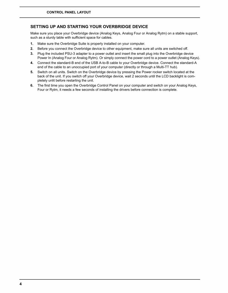
SETTING UP AND STARTING YOUR OVERBRIDGE DEVICE
Make sure you place your Overbridge device (Analog Keys, Analog Four or Analog Rytm) on a stable support, such as a sturdy table with sufficient space for cables.
1. Make sure the Overbridge Suite is properly installed on your computer.
2. Before you connect the Overbridge device to other equipment, make sure all units are switched off.
3. Plug the included PSU-3 adapter to a power outlet and insert the small plug into the Overbridge device Power In (Analog Four or Analog Rytm). Or simply connect the power cord to a power outlet (Analog Keys).
4. Connect the standard-B end of the USB A-to-B cable to your Overbridge device. Connect the standard-A end of the cable to an unoccupied port of your computer (directly or through a Multi-TT hub).
5. Switch on all units. Switch on the Overbridge device by pressing the Power rocker switch located at the back of the unit. If you switch off your Overbridge device, wait 2 seconds until the LCD backlight is com-pletely unlit before restarting the unit.
6. The first time you open the Overbridge Control Panel on your computer and switch on your Analog Keys, Four or Rytm, it needs a few seconds of installing the drivers before connection is complete.
4
QUICK START
QUICK START
FIVE-STEP WALKTHROUGH
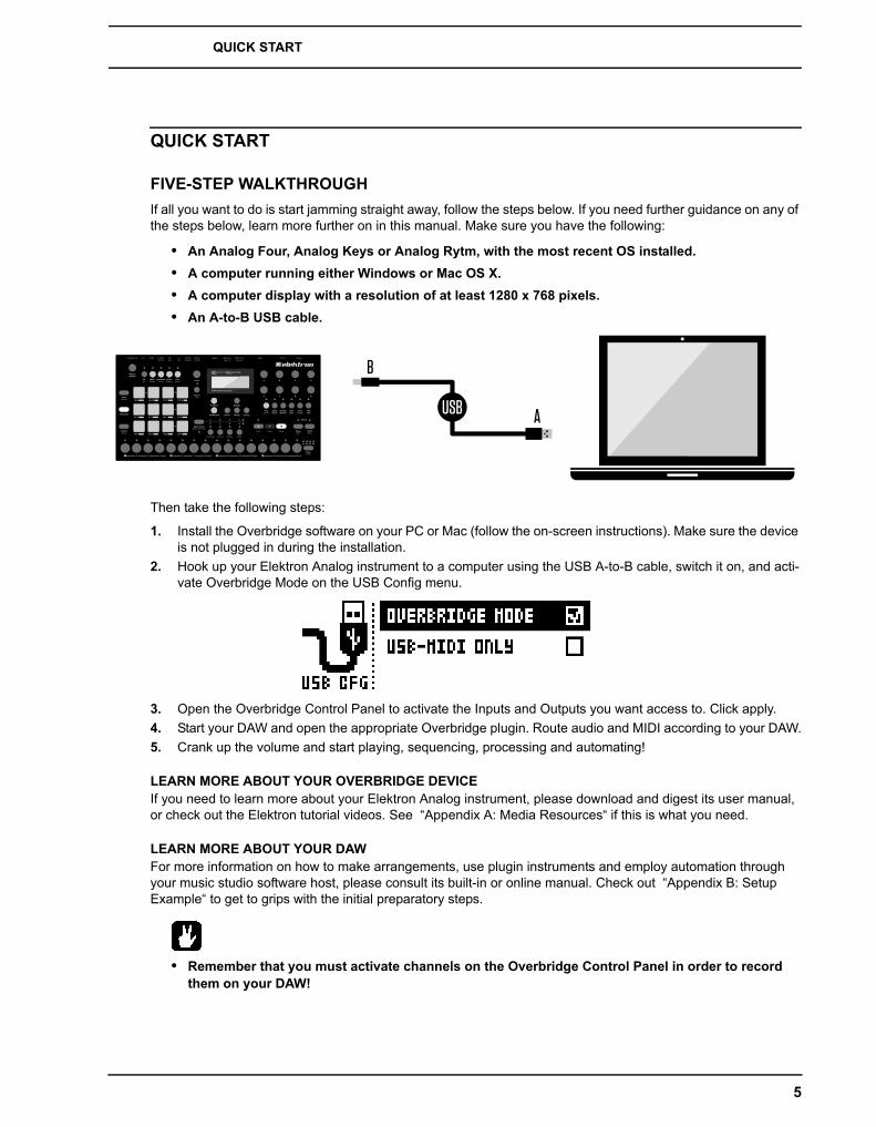
If all you want to do is start jamming straight away, follow the steps below. If you need further guidance on any of the steps below, learn more further on in this manual. Make sure you have the following:
• An Analog Four, Analog Keys or Analog Rytm, with the most recent OS installed.
• A computer running either Windows or Mac OS X.
• A computer display with a resolution of at least 1280 x 768 pixels.
• An A-to-B USB cable.
Then take the following steps:
1. Install the Overbridge software on your PC or Mac (follow the on-screen instructions). Make sure the device is not plugged in during the installation.
2. Hook up your Elektron Analog instrument to a computer using the USB A-to-B cable, switch it on, and acti-vate Overbridge Mode on the USB Config menu.
3. Open the Overbridge Control Panel to activate the Inputs and Outputs you want access to. Click apply.
4. Start your DAW and open the appropriate Overbridge plugin. Route audio and MIDI according to your DAW.
5. Crank up the volume and start playing, sequencing, processing and automating!
LEARN MORE ABOUT YOUR OVERBRIDGE DEVICEIf you need to learn more about your Elektron Analog instrument, please download and digest its user manual, or check out the Elektron tutorial videos. See “Appendix A: Media Resources“ if this is what you need.
LEARN MORE ABOUT YOUR DAWFor more information on how to make arrangements, use plugin instruments and employ automation through your music studio software host, please consult its built-in or online manual. Check out “Appendix B: Setup Example“ to get to grips with the initial preparatory steps.
• Remember that you must activate channels on the Overbridge Control Panel in order to record them on your DAW!
5
INSTALLING OVERBRIDGE
INSTALLING OVERBRIDGEInstalling the Overbridge Suite will take a swift few minutes on most contemporary computers. The procedure varies depending on which operating system you use, Windows or Mac. Read the instructions below.
SYSTEM REQUIREMENTS
The following items are required in order for you to start using Overbridge:
• One of the Elektron instruments Analog Four, Analog Keys or Analog Rytm, with the most recent OS installed.
• A computer running either Windows (7, 8 or 10) or Mac OS (10.7 - 10.10).
• A monitor with a resolution of at least 1280 x 768 pixels.
• An A-to-B USB cable.
INSTALLING
On Windows, unzip the installation software to its own folder. On Mac OS X, mount the dmg disk image by dou-ble-clicking it. Upgrade the operating system on your Elektron device according to the instructions included when you download an OS for Keys, Four or Rytm from the Support section on the Elektron website.
• The first time you install Overbridge, make sure you use the latest OS version for both Overbridge and your devices in order to ensure matching protocols. Downgrading the operating system of Overbridge or your device is not recommended.
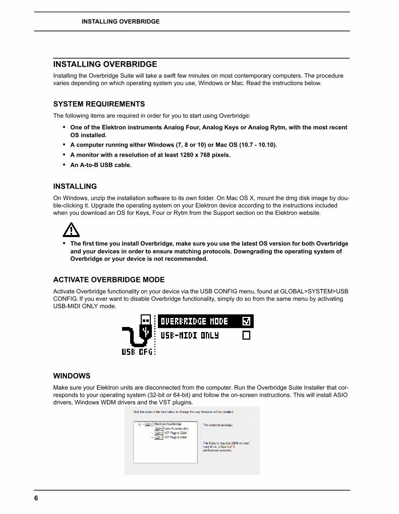
ACTIVATE OVERBRIDGE MODE
Activate Overbridge functionality on your device via the USB CONFIG menu, found at GLOBAL>SYSTEM>USB CONFIG. If you ever want to disable Overbridge functionality, simply do so from the same menu by activating USB-MIDI ONLY mode.
WINDOWS
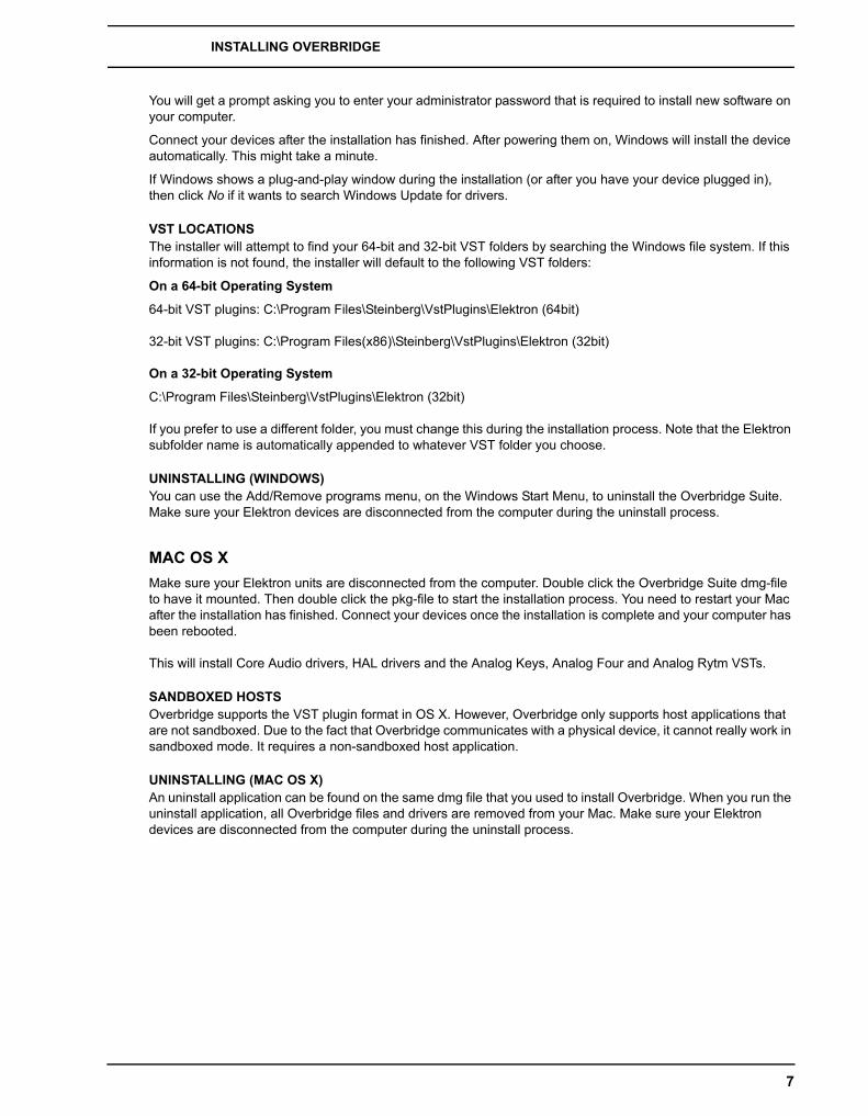
Make sure your Elektron units are disconnected from the computer. Run the Overbridge Suite Installer that cor-responds to your operating system (32-bit or 64-bit) and follow the on-screen instructions. This will install ASIO drivers, Windows WDM drivers and the VST plugins.
6
INSTALLING OVERBRIDGE
You will get a prompt asking you to enter your administrator password that is required to install new software on your computer.
Connect your devices after the installation has finished. After powering them on, Windows will install the device automatically. This might take a minute.
If Windows shows a plug-and-play window during the installation (or after you have your device plugged in), then click No if it wants to search Windows Update for drivers.
VST LOCATIONSThe installer will attempt to find your 64-bit and 32-bit VST folders by searching the Windows file system. If this information is not found, the installer will default to the following VST folders:
On a 64-bit Operating System
64-bit VST plugins: C:\Program Files\Steinberg\VstPlugins\Elektron (64bit)
32-bit VST plugins: C:\Program Files(x86)\Steinberg\VstPlugins\Elektron (32bit)
On a 32-bit Operating System
C:\Program Files\Steinberg\VstPlugins\Elektron (32bit)
If you prefer to use a different folder, you must change this during the installation process. Note that the Elektron subfolder name is automatically appended to whatever VST folder you choose.
UNINSTALLING (WINDOWS)You can use the Add/Remove programs menu, on the Windows Start Menu, to uninstall the Overbridge Suite. Make sure your Elektron devices are disconnected from the computer during the uninstall process.
MAC OS X
Make sure your Elektron units are disconnected from the computer. Double click the Overbridge Suite dmg-file to have it mounted. Then double click the pkg-file to start the installation process. You need to restart your Mac after the installation has finished. Connect your devices once the installation is complete and your computer has been rebooted.
This will install Core Audio drivers, HAL drivers and the Analog Keys, Analog Four and Analog Rytm VSTs.
SANDBOXED HOSTSOverbridge supports the VST plugin format in OS X. However, Overbridge only supports host applications that are not sandboxed. Due to the fact that Overbridge communicates with a physical device, it cannot really work in sandboxed mode. It requires a non-sandboxed host application.
UNINSTALLING (MAC OS X)An uninstall application can be found on the same dmg file that you used to install Overbridge. When you run the uninstall application, all Overbridge files and drivers are removed from your Mac. Make sure your Elektron devices are disconnected from the computer during the uninstall process.
7

USB AND BANDWIDTH
USB AND BANDWIDTHYour computer needs to have at least one unoccupied USB port dedicated to the Overbridge connection.
If you want proper USB audio streaming performance (as many channels as possible) when using multiple Overbridge units, use a Multiple Transaction Translator (Multi-TT) USB hub. Most USB hubs only have Single Transaction Translation.
A Multi-TT hub is required in order to utilize the full 12 Mbit/s bandwidth of multiple USB Full Speed devices at the same time. With a Single Transaction Translator USB hub, all USB Full Speed (12 Mbit/s) devices will have to share the same Full Speed bandwidth, that is 12 Mbit/s even if the other side of the USB bus is 480Mbit/s or higher. With a Multi-TT hub each Full Speed device will get its own dedicated 12 Mbit/s bandwidth merged into the 480Mbit/s host speed.
LIMITATIONS
The Analog Keys, Four and Rytm are USB Full Speed devices, each with a maximum bandwidth of 12 Mbit/s. This limits the number of audio channels that can be used at the same time without running out of bandwidth. Depending on the bit depth (16-bit or 24-bit), you get different numbers of channels. In order to economize the bandwidth in a way that makes sense, the Overbridge Control Panel allows you to enable/disable the input- and output channels that you want to use. 16-bit quality gives you access to more channels than 24-bit does.
Depending on both your computer and your USB setup (hubs and other devices), you will be able to use up to 10 channels at once in 16-bit quality. However, this might be possible only on highly optimized systems. On most systems, you will be able to use at least 6 or 8 channels at once. You will most likely be able to multi-track record all channels of both Analog Keys/Four devices, and up to 8 channels from the Analog Rytm, directly into your DAW.
A maximum of 8 channels per direction is supported per Overbridge device.
8
AUDIO INTERFACE
AUDIO INTERFACEOverbridge offers audio interface functionality directly from your Elektron device. This means that individual voices of your Elektron device are exposed as separate audio input channels in your computer. There are also audio output channels that can be routed directly into the synth voices, as well as to the main output bus.
Note that, when you route audio from your DAW into the Track output channels, you have to make sure that the VCA in the corresponding Synth/Drum Track is triggered. Program a pattern on the machine that both gates and filters the audio that is routed through the voice. If you want the audio to just pass through, you might consider using infinite release time on your Track Sound.
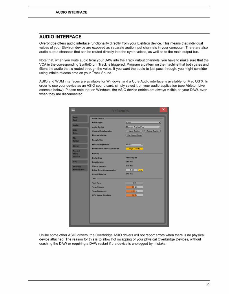
ASIO and WDM interfaces are available for Windows, and a Core Audio interface is available for Mac OS X. In order to use your device as an ASIO sound card, simply select it on your audio application (see Ableton Live example below). Please note that on Windows, the ASIO device entries are always visible on your DAW, even when they are disconnected.
Unlike some other ASIO drivers, the Overbridge ASIO drivers will not report errors when there is no physical device attached. The reason for this is to allow hot swapping of your physical Overbridge Devices, without crashing the DAW or requiring a DAW restart if the device is unplugged by mistake.
9

AUDIO INTERFACE
ASIO CHANNEL TABLE
If your DAW cannot display the names of the ASIO channels, use the tables below for reference. The input and output channels differ depending on the Overbridge device you use.
Note that the Main L/R output is mixed into the Main Out, and that the Synth/Drum Track outputs are mixed in before the filters/overdrive. On the Analog Rytm, the Main FX Left and Right Output channels are mixed in together with the Main Out before the master Distortion and Compression.
ANALOG KEYS / FOUR CHANNELS
ANALOG RYTM CHANNELS
KEYS / FOUR INPUT ASIO INPUT ID KEYS / FOUR OUTPUT ASIO OUTPUT ID
MAIN L 1 MAIN L 1
MAIN R 2 MAIN R 2
SYNTH TRACK 1 3 SYNTH TRACK 1 3
SYNTH TRACK 2 4 SYNTH TRACK 2 4
SYNTH TRACK 3 5 SYNTH TRACK 3 5
SYNTH TRACK 4 6 SYNTH TRACK 4 6
EXTERNAL IN L 7
EXTERNAL IN R 8
ANALOG RYTM INPUT ASIO INPUT ID ANALOG RYTM OUTPUT ASIO OUTPUT ID
MAIN L 1 MAIN L 1
MAIN R 2 MAIN R 2
BD TRACK 1 3 MAIN FX L 3
SD TRACK 2 4 MAIN FX R 4
RS/CP TRACK 3/4 5 BD 1 5
BT TRACK 5 6 SD 2 6
LT TRACK 6 7 RS/CP 3/4 7
MT/HT TRACK 7/8 8 BT 5 8
CH/OH TRACK 9/10 9 LT 6 9
CY/CB TRACK 11/12 10 MT/HT 7/8 10
CH/OH 9/10 11
CY/CB 11/12 12
10
THE CONTROL PANEL
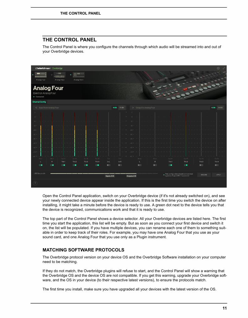
THE CONTROL PANELThe Control Panel is where you configure the channels through which audio will be streamed into and out of your Overbridge devices.
Open the Control Panel application, switch on your Overbridge device (if it's not already switched on), and see your newly connected device appear inside the application. If this is the first time you switch the device on after installing, it might take a minute before the device is ready to use. A green dot next to the device tells you that the device is recognized, communications work and that it is ready to use.
The top part of the Control Panel shows a device selector. All your Overbridge devices are listed here. The first time you start the application, this list will be empty. But as soon as you connect your first device and switch it on, the list will be populated. If you have multiple devices, you can rename each one of them to something suit-able in order to keep track of their roles. For example, you may have one Analog Four that you use as your sound card, and one Analog Four that you use only as a Plugin instrument.
MATCHING SOFTWARE PROTOCOLS
The Overbridge protocol version on your device OS and the Overbridge Software installation on your computer need to be matching.
If they do not match, the Overbridge plugins will refuse to start, and the Control Panel will show a warning that the Overbridge OS and the device OS are not compatible. If you get this warning, upgrade your Overbridge soft-ware, and the OS in your device (to their respective latest versions), to ensure the protocols match.
The first time you install, make sure you have upgraded all your devices with the latest version of the OS.
11
THE CONTROL PANEL
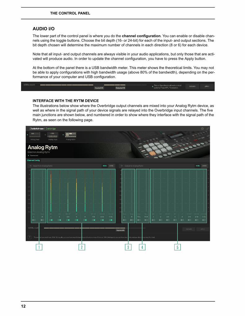
AUDIO I/O
The lower part of the control panel is where you do the channel configuration. You can enable or disable chan-nels using the toggle buttons. Choose the bit depth (16- or 24-bit) for each of the input- and output sections. The bit depth chosen will determine the maximum number of channels in each direction (8 or 6) for each device.
Note that all input- and output channels are always visible in your audio applications, but only those that are acti-vated will produce audio. In order to update the channel configuration, you have to press the Apply button.
At the bottom of the panel there is a USB bandwidth meter. This meter shows the theoretical limits. You may not be able to apply configurations with high bandwidth usage (above 80% of the bandwidth), depending on the per-formance of your computer and USB configuration.
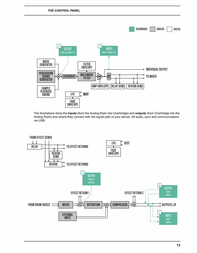
INTERFACE WITH THE RYTM DEVICEThe illustrations below show where the Overbridge output channels are mixed into your Analog Rytm device, as well as where in the signal path of your device signals are relayed into the Overbridge input channels. The five main junctions are shown below, and numbered in order to show where they interface with the signal path of the Rytm, as seen on the following page.
12
THE CONTROL PANEL
The illustrations show the inputs (from the Analog Rytm into Overbridge) and outputs (from Overbridge into the Analog Rytm) and where they connect with the signal path of your device. All audio, sync and communications via USB.
OVERBRIDGE ANALOG DIGITAL
PERCUSSIONSOUND
GENERATOR
SAMPLEPLAYBACK
ENGINE
OVERDRIVE MULTIMODEFILTER AMP
NOISEGENERATOR FILTER
ENVELOPE
AMP ENVELOPE
FADEENVELOPE
LFO DEST
PAN
DELAY SEND REVERB SEND
TO MIXER
INDIVIDUAL OUTPUT
OUTPUTVOICE 1-8 (TRACK 1-12)
5 INPUT
VOICE 1-8 (TRACK 1-12)
2
MIXER
EXTERNALINPUT
DISTORTION COMPRESSOR
REVERBSEND
DELAY
REVERB
FROM EFFECT SENDS
EFFECT RETURN 1
FROM DRUM VOICES OUTPUTS L/R
EFFECT RETURN 2
TO EFFECT RETURNSFADE
ENVELOPE
LFO DEST
TO EFFECT RETURNS
OUTPUTMAIN FX LMAIN FX R
4
OUTPUTMAIN LMAIN R
3
INPUTMAIN LMAIN R
1
13
THE CONTROL PANEL
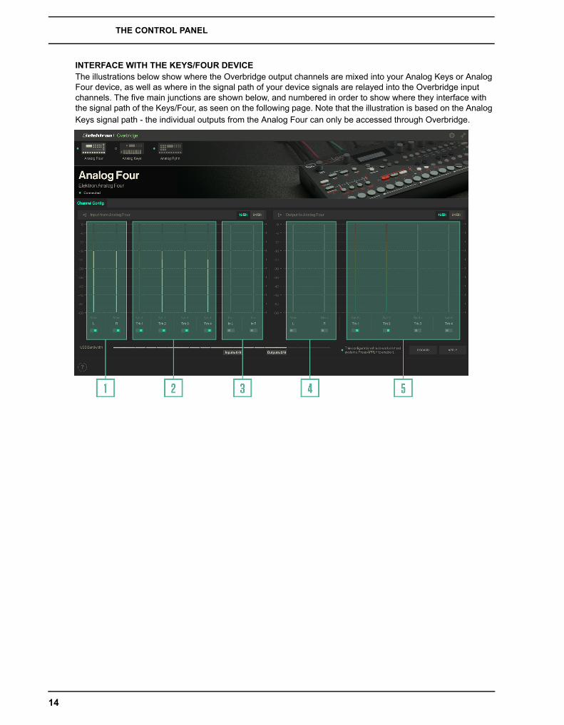
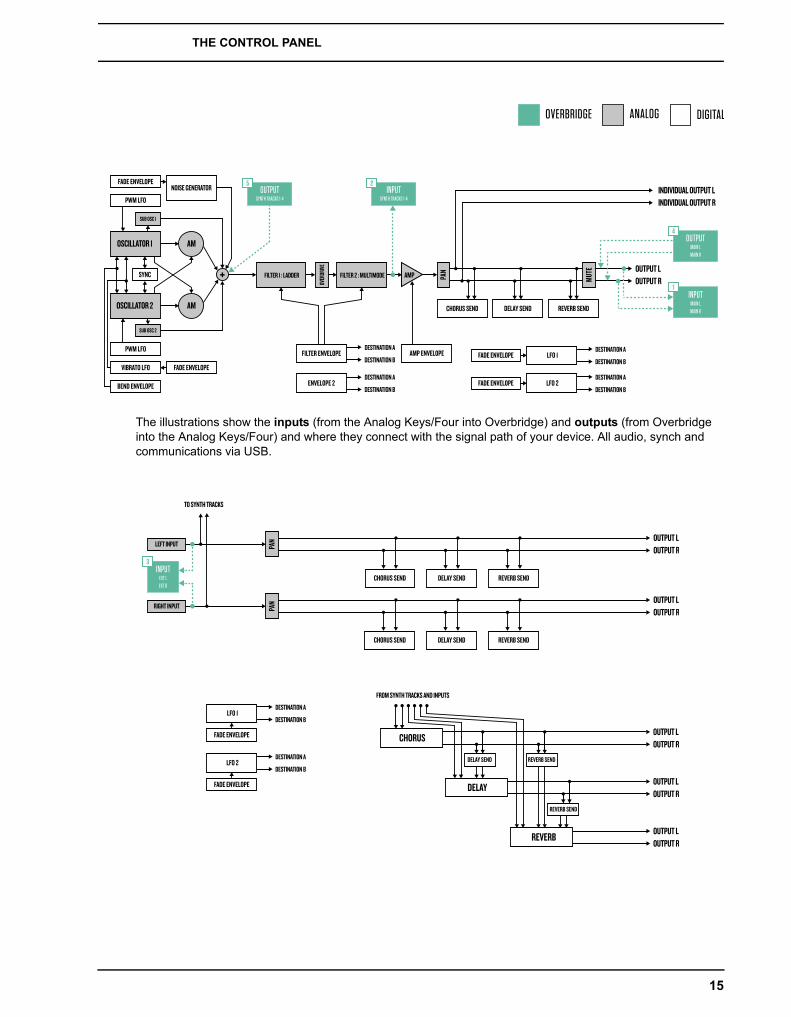
INTERFACE WITH THE KEYS/FOUR DEVICEThe illustrations below show where the Overbridge output channels are mixed into your Analog Keys or Analog Four device, as well as where in the signal path of your device signals are relayed into the Overbridge input channels. The five main junctions are shown below, and numbered in order to show where they interface with the signal path of the Keys/Four, as seen on the following page. Note that the illustration is based on the Analog Keys signal path - the individual outputs from the Analog Four can only be accessed through Overbridge.
14
THE CONTROL PANEL
The illustrations show the inputs (from the Analog Keys/Four into Overbridge) and outputs (from Overbridge into the Analog Keys/Four) and where they connect with the signal path of your device. All audio, synch and communications via USB.
OVERBRIDGE ANALOG DIGITAL
INDIVIDUAL OUTPUT LINDIVIDUAL OUTPUT R
OSCILLATOR 1
FILTER 1 : LADDER FILTER 2 : MULTIMODE
OVER
DRIVE
PAN
MUTE
AM
AMOSCILLATOR 2
AMP
SUB OSC 2
SUB OSC 1
NOISE GENERATOR
PWM LFO
FADE ENVELOPE
PWM LFO
FADE ENVELOPE
FADE ENVELOPEFILTER ENVELOPE AMP ENVELOPE
CHORUS SEND DELAY SEND REVERB SEND
LFO 1
FADE ENVELOPE LFO 2ENVELOPE 2
VIBRATO LFO
BEND ENVELOPE
SYNCOUTPUT LOUTPUT R
DESTINATION A
DESTINATION BDESTINATION A
DESTINATION B
DESTINATION A
DESTINATION B
DESTINATION A
DESTINATION B
OUTPUTSYNTH TRACKS 1-4
5INPUT
SYNTH TRACKS 1-4
2
OUTPUTMAIN LMAIN R
4
INPUTMAIN LMAIN R
1
LEFT INPUT
RIGHT INPUT
PAN
PAN
CHORUS SEND DELAY SEND REVERB SEND
CHORUS SEND DELAY SEND REVERB SEND
FADE ENVELOPE
DELAY SEND
REVERB SEND
REVERB SEND
FADE ENVELOPE
LFO 1
CHORUS
DELAY
REVERB
LFO 2
TO SYNTH TRACKS
FROM SYNTH TRACKS AND INPUTS
OUTPUT LOUTPUT R
OUTPUT LOUTPUT R
OUTPUT LOUTPUT R
OUTPUT LOUTPUT R
OUTPUT LOUTPUT R
DESTINATION A
DESTINATION B
DESTINATION A
DESTINATION B
INPUTEXT LEXT R
3
15

THE CONTROL PANEL
GENERAL PERFORMANCE SETTINGS
When you click one of the small icons (gear or wrench) in the top right corner of the Control Panel, a sidebar will appear on the right-hand side. The gear brings up general settings for the plugin performance (effective once you open your Keys, Four or Rytm plugin from your DAW) and the wrench presents Sound Card functionality settings.
GENERAL PLUGIN PERFORMANCE SETTINGSSet the buffer size between plugin and device here: 64, 128, 256 or 512 samples. The plugin buffer size is used only by audio applications that do not select their own buffer size.
Use the UI (plugin) Zoom level slider to set the size of the plugin window: between 50 (small) and 150 (large). Activate/deactivate plugin Tooltips, Sidebar menu docking (also applies to the Control Panel window), and Mousewheel control for the parameter knobs and sliders, by clicking the toggler button next to each setting. These settings are also found on the Plugin editor sidebar when clicking the gear icon.
SOUND CARD AND DRIVER PERFORMANCE SETTINGSSound card buffer size (64, 128, 256 or 512 samples) and driver performance mode (relaxed, relaxed normal, normal, fast, rapid and highspeed) can be set here. The expected input and output latency implications of the different buffer size/performance mode configurations are shown directly below.
If you have a powerful computer, you can choose a higher driver performance mode (which lowers latency) and a lower buffer size (which also lowers latency).
The driver performance options will not appear on the Mac OS X version of the Control Panel. All Mac audio applications are able select their own buffer size, and the device driver always operates in a high performance manner.
The bottom section of the sidebar lets you select which of the connected devices you wish to use as a Sound Card.
MULTIPLE SOUND CARDS
WINDOWSWhen set to be used as sound cards, ASIO/WDM/USB-MIDI interfaces will be enabled for the Overbridge devices. Only one device of each type may have sound card functionality enabled. This is a limitation of the present ASIO system.
MACOn Mac OS X, all your Overbridge devices may act as sound cards simultaneously.
16
THE CONTROL PANEL
CONNECTION STATUS INDICATOR
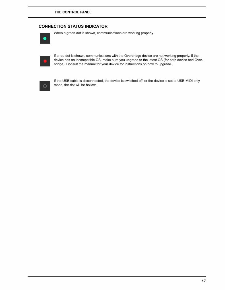
When a green dot is shown, communications are working properly.
If a red dot is shown, communications with the Overbridge device are not working properly. If the device has an incompatible OS, make sure you upgrade to the latest OS (for both device and Over-bridge). Consult the manual for your device for instructions on how to upgrade.
If the USB cable is disconnected, the device is switched off, or the device is set to USB-MIDI only mode, the dot will be hollow.
17
THE PLUGINS
THE PLUGINSAll Elektron instruments that are Overbridge enabled may be used as VST plugins, complete with automation of parameters, modulation and macros. The complete set of parameters used to form and process sound on your Overbridge device can be accessed by using the graphical user interface controls of the plugin editor.
The plugin communicates directly with the Elektron device via USB and streams the individual channels of audio from the device into your DAW (and, if you so desire, from the DAW outputs into your device for analog process-ing), with latency compensation taken care of by the plugin and the DAW.
Remember that this is a real Analog plugin. It will only work for as long as your Overbridge device remains con-nected to your computer. Do not disconnect the USB cable during operation, as this is the conduit through which the multichannel audio, as well as the sync, control and communications data, between Elektron device and computer is being sent, in real time and in both directions.
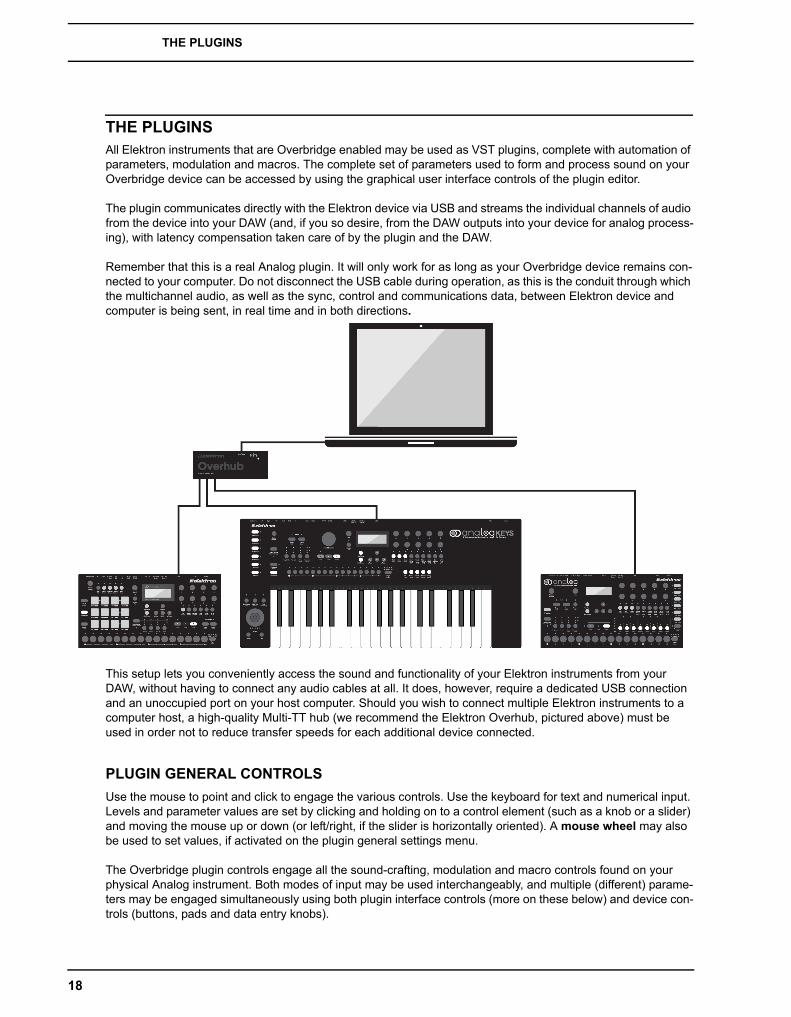
This setup lets you conveniently access the sound and functionality of your Elektron instruments from your DAW, without having to connect any audio cables at all. It does, however, require a dedicated USB connection and an unoccupied port on your host computer. Should you wish to connect multiple Elektron instruments to a computer host, a high-quality Multi-TT hub (we recommend the Elektron Overhub, pictured above) must be used in order not to reduce transfer speeds for each additional device connected.
PLUGIN GENERAL CONTROLS
Use the mouse to point and click to engage the various controls. Use the keyboard for text and numerical input. Levels and parameter values are set by clicking and holding on to a control element (such as a knob or a slider) and moving the mouse up or down (or left/right, if the slider is horizontally oriented). A mouse wheel may also be used to set values, if activated on the plugin general settings menu.
The Overbridge plugin controls engage all the sound-crafting, modulation and macro controls found on your physical Analog instrument. Both modes of input may be used interchangeably, and multiple (different) parame-ters may be engaged simultaneously using both plugin interface controls (more on these below) and device con-trols (buttons, pads and data entry knobs).
18

THE PLUGINS
Please consult the manuals for the Analog Keys, Analog Four and Analog Rytm if you need to brush up on your knowledge of what the different parameters do (see “Appendix A: Media Resources“).
You can also enable Tooltips, found on the general settings menu of the plugin editor. Click the gear symbol in the top right corner of the window, then set the Enable Tooltips toggler to on. When on, a short description of any control element you point to with the mouse will be provided.
• Enable the Tooltips, found on the Plugin editor settings menu (top right gear icon), to get a short description of any parameter or control element you hover over with the mouse pointer.
CONTROL ELEMENTS AND INDICATORSThe following is an overview of the general control elements and indicators used on the Analog Keys, Four and Rytm plugins.
INFO BANNER When the plugin is in a state where a transaction is being made, such as when syncing the device with Recall, or when sample storage is being accessed, an info banner will appear from the bottom left of the screen. The banner is colored blue when it shows information or poses a question, yellow when an alert or a suggestion is given, and if it is red, it means an error has occured. When a banner shows a Yes/No prompt, click one of the alternatives to continue.
TAB Click a tab to select a page. The top menu bar has two tabs: Kit Editor and Sound Browser. If the Kit editor tab is selected, you will find the following bar of tabs directly below: A Kit page (general settings and perfor-mance macros), the individual Synth/Drum Track pages, the FX Track page, and (Analog Keys/Four only) the CV Track page. In some cases, tabs give you access to subpages as well, like the oscillator section on the Analog Keys/Four plugin, where the TUNE tab accesses the tonal parameters of the oscillator and MOD instead brings the oscillator modulation parameters into view.
TEXT INPUT BOX Click once in a text input box to edit a name. Once a new name has been entered using the computer keyboard, press enter to apply. If, for example, the name of a Kit or a Synth Track Sound is changed in the text input box, the new name of the Kit or Sound will be set instantly on your Overbridge device once you press enter.
VALUE INPUT BOX Click twice in the center of a parameter dial or below a slider in order to set its value manu-ally using the computer keyboard. Type a (-) sign before typing in the figures in order to enter a negative value (valid only for bipolar dials). Press enter when done. If the value entered is too small or too large, the smallest or largest viable value will appear instead (usually, the range is -64 to 63 or 0 to 127).
19
THE PLUGINS
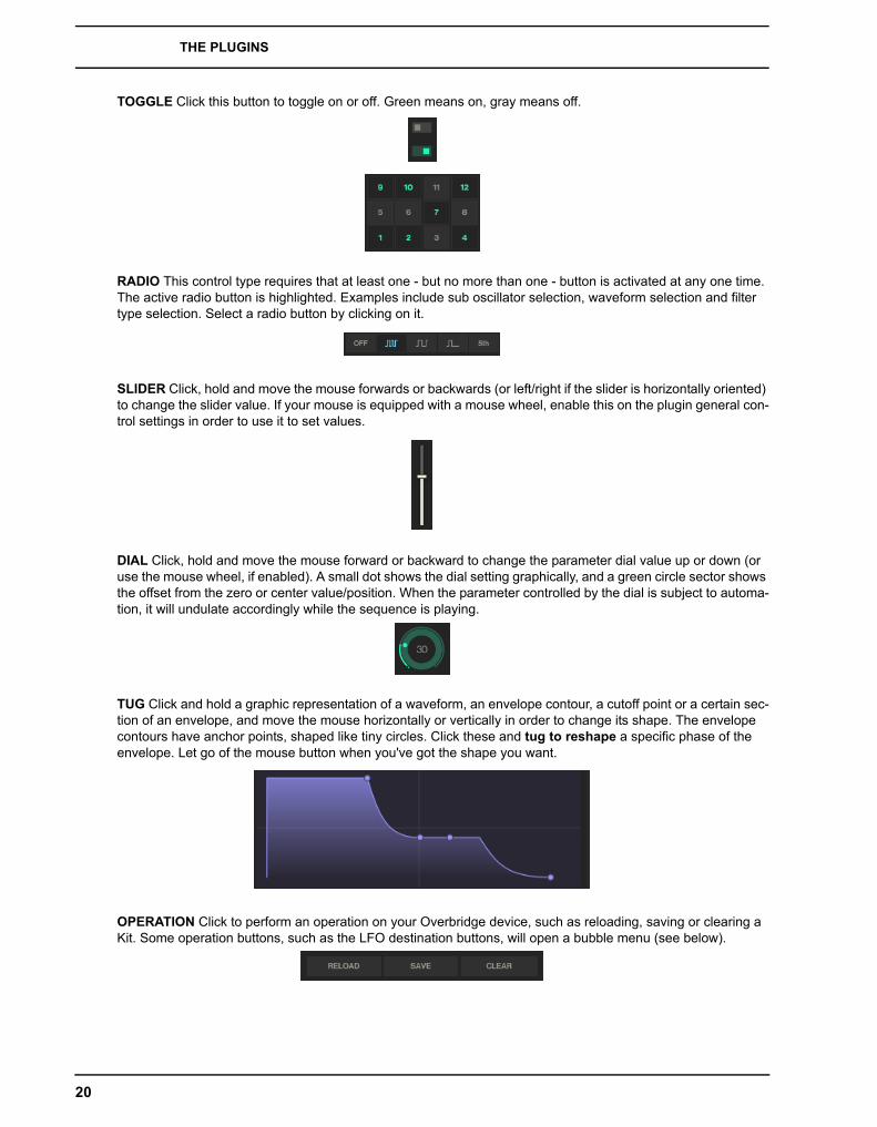
TOGGLE Click this button to toggle on or off. Green means on, gray means off.
RADIO This control type requires that at least one - but no more than one - button is activated at any one time. The active radio button is highlighted. Examples include sub oscillator selection, waveform selection and filter type selection. Select a radio button by clicking on it.
SLIDER Click, hold and move the mouse forwards or backwards (or left/right if the slider is horizontally oriented) to change the slider value. If your mouse is equipped with a mouse wheel, enable this on the plugin general con-trol settings in order to use it to set values.
DIAL Click, hold and move the mouse forward or backward to change the parameter dial value up or down (or use the mouse wheel, if enabled). A small dot shows the dial setting graphically, and a green circle sector shows the offset from the zero or center value/position. When the parameter controlled by the dial is subject to automa-tion, it will undulate accordingly while the sequence is playing.
TUG Click and hold a graphic representation of a waveform, an envelope contour, a cutoff point or a certain sec-tion of an envelope, and move the mouse horizontally or vertically in order to change its shape. The envelope contours have anchor points, shaped like tiny circles. Click these and tug to reshape a specific phase of the envelope. Let go of the mouse button when you've got the shape you want.
OPERATION Click to perform an operation on your Overbridge device, such as reloading, saving or clearing a Kit. Some operation buttons, such as the LFO destination buttons, will open a bubble menu (see below).
20
THE PLUGINS
GENERAL PLUGIN PERFORMANCE SETTINGS Click to open a menu with general settings for the plugin, such as buffer size, plugin window dimensions, tooltips, sidebar and mousewheel on/off.
DEVICE SETTINGS Click to open a menu with device settings, such as sequencer sync, machine state recall and sidechain input audio routing to the plugin.
SOUND POOL BROWSER Click to quickly access the Sound Pool of your active Kit. If you access the Sound Pool from a Synth/Drum Track page, preview a Sound by clicking it once and playing/triggering a note. Load a Sound to the active Track by double-clicking it.
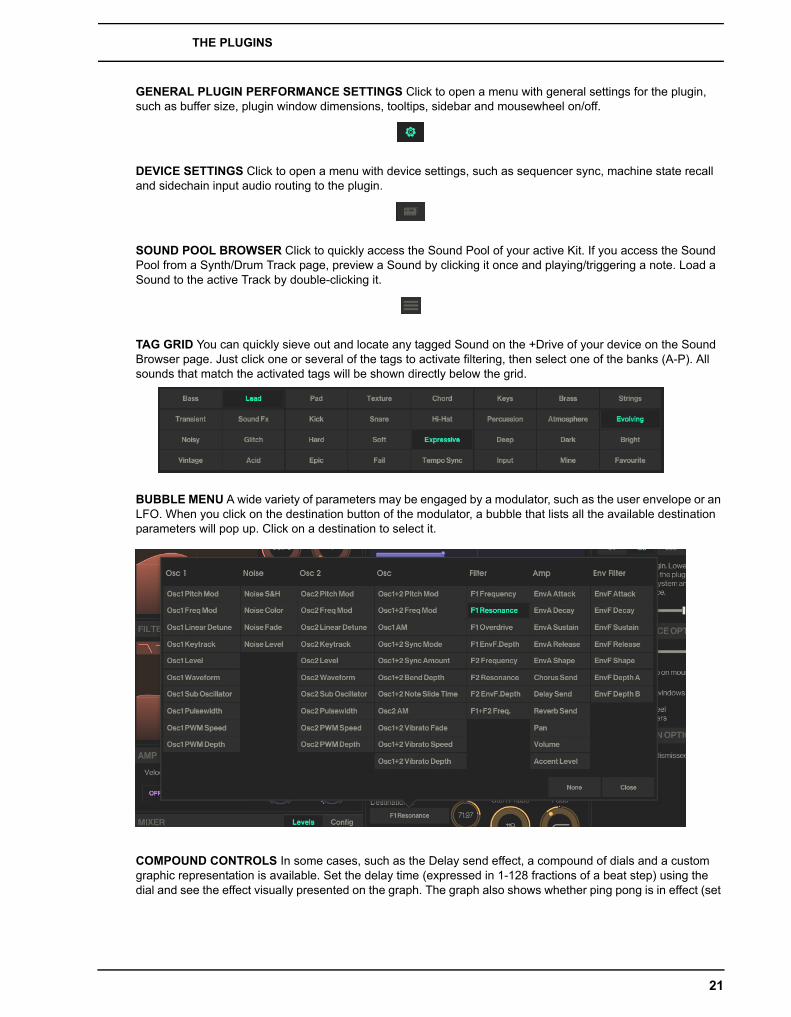
TAG GRID You can quickly sieve out and locate any tagged Sound on the +Drive of your device on the Sound Browser page. Just click one or several of the tags to activate filtering, then select one of the banks (A-P). All sounds that match the activated tags will be shown directly below the grid.
BUBBLE MENU A wide variety of parameters may be engaged by a modulator, such as the user envelope or an LFO. When you click on the destination button of the modulator, a bubble that lists all the available destination parameters will pop up. Click on a destination to select it.
COMPOUND CONTROLS In some cases, such as the Delay send effect, a compound of dials and a custom graphic representation is available. Set the delay time (expressed in 1-128 fractions of a beat step) using the dial and see the effect visually presented on the graph. The graph also shows whether ping pong is in effect (set
21
THE PLUGINS
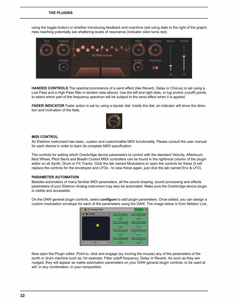
using the toggle button) or whether introducing feedback and overdrive (set using dials to the right of the graph) risks reaching potentially ear-shattering levels of resonance (indicator color turns red).
HANDED CONTROLS The spectral prominence of a send effect (like Reverb, Delay or Chorus) is set using a Low Pass and a High Pass filter in tandem (see above). Use the left and right dials, or tug anchor (cutoff) points, to select which part of the frequency spectrum will be subject to the send effect when it is applied.
FADER INDICATOR Fader action is set by using a bipolar dial. Inside the dial, an indicator will show the direc-tion and inclination of the fade.
MIDI CONTROLAn Elektron instrument has basic, custom and customizable MIDI functionality. Please consult the user manual for each device in order to learn its complete MIDI specification.
The controls for setting which Overbridge device parameters to control with the standard Velocity, Aftertouch, Mod Wheel, Pitch Bend and Breath Control MIDI controllers can be found in the rightmost column of the plugin editor on all Synth, Drum or FX Tracks. Click the tab named Modulators to open the controls for these (it will replace the controls for the envelopes and LFOs - to view these again, just click the tab named Env & LFO).
PARAMETER AUTOMATIONBesides automation of many familiar MIDI parameters, all the sound shaping, sound processing and effects parameters of your Elektron Analog instrument may also be automated. Make sure the Overbridge device plugin is visible and accessible.
On the DAW general plugin controls, select configure to add plugin parameters. Once added, you can design a custom modulation envelope for each of the parameters using the DAW. The image below is from Ableton Live.
Now open the Plugin editor. Point to, click and engage (by moving the mouse) any of the parameters of the synth or drum machine such as, for example, Filter cutoff frequency, Delay or Reverb. As soon as they are nudged, they will appear as viable automation parameters on your DAW general plugin controls, to be used at will, in any combination, in your composition.
22
THE PLUGINS
When you engage a parameter controlled by a dial or slider, the depth of the parameter automation is set by clicking, holding and moving the mouse up or down until the desired depth is achieved (or, if enabled, by using the mouse wheel).
Like the majority of Overbridge device controls, the automation parameters may of course also be added, and depth set, simply by engaging the physical controls (knobs) on your Elektron instrument, while your DAW is set to configure/add plugin parameters.
All sound-shaping, modulation and effects parameters, as well as CV parameters on the Analog Four and Keys, sample manipulation parameters on the Analog Rytm, and even the performance macros, can be automated using the DAW.
Remember, the plugin editor is an interface for controlling your hardware device. Altering the sound parameters from the plugin will alter the parameter settings on the device. In order to keep desirable changes, you need to use Kit Save on the plugin (by clicking the Save button on the Kit page) or on the device itself.
• Note that, when parameter automation is going on, your kit is continuously altered on the device each time a new parameter value is sent from the DAW. Remember to save kits that you treasure, so that you can reload to the last saved state when needed.
For more information on how to use and manage automation, please consult the instructions specific to the DAW you are using.
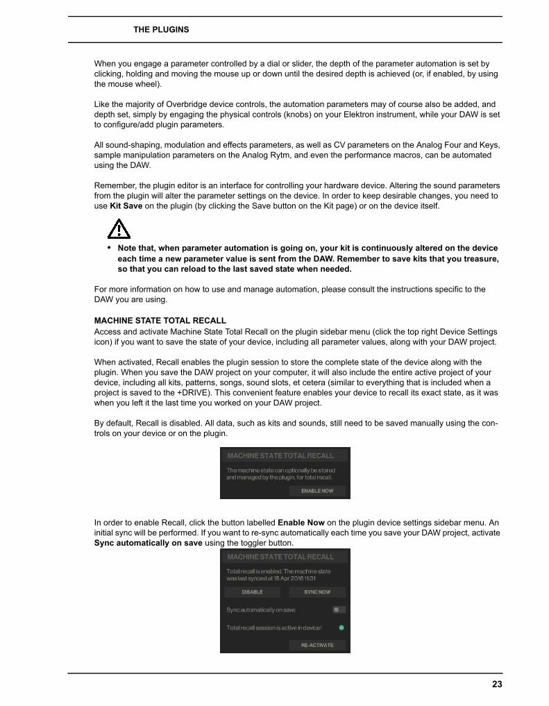
MACHINE STATE TOTAL RECALLAccess and activate Machine State Total Recall on the plugin sidebar menu (click the top right Device Settings icon) if you want to save the state of your device, including all parameter values, along with your DAW project.
When activated, Recall enables the plugin session to store the complete state of the device along with the plugin. When you save the DAW project on your computer, it will also include the entire active project of your device, including all kits, patterns, songs, sound slots, et cetera (similar to everything that is included when a project is saved to the +DRIVE). This convenient feature enables your device to recall its exact state, as it was when you left it the last time you worked on your DAW project.
By default, Recall is disabled. All data, such as kits and sounds, still need to be saved manually using the con-trols on your device or on the plugin.
In order to enable Recall, click the button labelled Enable Now on the plugin device settings sidebar menu. An initial sync will be performed. If you want to re-sync automatically each time you save your DAW project, activate Sync automatically on save using the toggler button.
23
THE PLUGINS
Note that this may cause your DAW save operation to take a couple of extra seconds. The alternative (if synch automatically on save is left deactivated) is to sync manually. Just click the button called Sync Now on the plugin (device settings) each time you have a state that you want to save in its entirety. If you do not wish to use the recall functionality, you can deactivate it by clicking the Disable button.
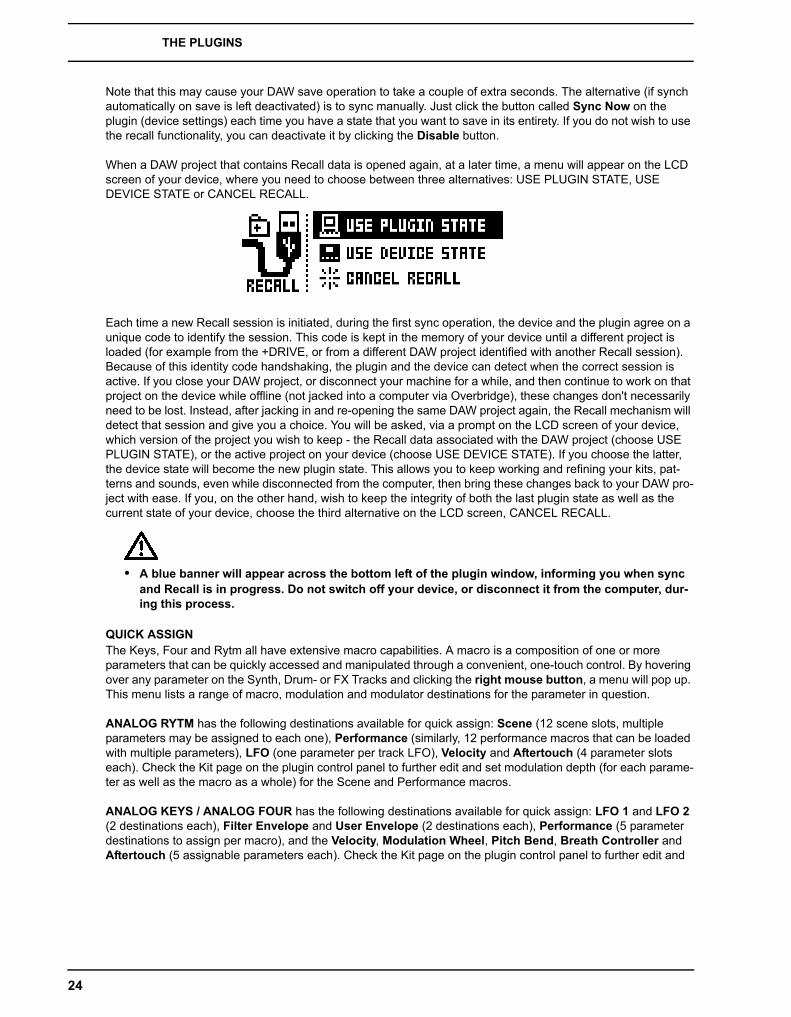
When a DAW project that contains Recall data is opened again, at a later time, a menu will appear on the LCD screen of your device, where you need to choose between three alternatives: USE PLUGIN STATE, USE DEVICE STATE or CANCEL RECALL.
Each time a new Recall session is initiated, during the first sync operation, the device and the plugin agree on a unique code to identify the session. This code is kept in the memory of your device until a different project is loaded (for example from the +DRIVE, or from a different DAW project identified with another Recall session). Because of this identity code handshaking, the plugin and the device can detect when the correct session is active. If you close your DAW project, or disconnect your machine for a while, and then continue to work on that project on the device while offline (not jacked into a computer via Overbridge), these changes don't necessarily need to be lost. Instead, after jacking in and re-opening the same DAW project again, the Recall mechanism will detect that session and give you a choice. You will be asked, via a prompt on the LCD screen of your device, which version of the project you wish to keep - the Recall data associated with the DAW project (choose USE PLUGIN STATE), or the active project on your device (choose USE DEVICE STATE). If you choose the latter, the device state will become the new plugin state. This allows you to keep working and refining your kits, pat-terns and sounds, even while disconnected from the computer, then bring these changes back to your DAW pro-ject with ease. If you, on the other hand, wish to keep the integrity of both the last plugin state as well as the current state of your device, choose the third alternative on the LCD screen, CANCEL RECALL.
• A blue banner will appear across the bottom left of the plugin window, informing you when sync and Recall is in progress. Do not switch off your device, or disconnect it from the computer, dur-ing this process.
QUICK ASSIGNThe Keys, Four and Rytm all have extensive macro capabilities. A macro is a composition of one or more parameters that can be quickly accessed and manipulated through a convenient, one-touch control. By hovering over any parameter on the Synth, Drum- or FX Tracks and clicking the right mouse button, a menu will pop up. This menu lists a range of macro, modulation and modulator destinations for the parameter in question.
ANALOG RYTM has the following destinations available for quick assign: Scene (12 scene slots, multiple parameters may be assigned to each one), Performance (similarly, 12 performance macros that can be loaded with multiple parameters), LFO (one parameter per track LFO), Velocity and Aftertouch (4 parameter slots each). Check the Kit page on the plugin control panel to further edit and set modulation depth (for each parame-ter as well as the macro as a whole) for the Scene and Performance macros.
ANALOG KEYS / ANALOG FOUR has the following destinations available for quick assign: LFO 1 and LFO 2 (2 destinations each), Filter Envelope and User Envelope (2 destinations each), Performance (5 parameter destinations to assign per macro), and the Velocity, Modulation Wheel, Pitch Bend, Breath Controller and Aftertouch (5 assignable parameters each). Check the Kit page on the plugin control panel to further edit and
24

THE PLUGINS
set modulation depth (for each parameter as well as the macro as a whole) for the Performance macro (shown below).
As an example, the quickest way to set up a Scene macro on the Analog Rytm, for instance, is to hover over a host of parameters, one at a time, right click and select one of the Scene destinations (BD 1 for example). Once you've collected all the parameters you want for the macro, go to the Kit page and click the BD 1 Scene pad top right inset square (Edit) to review and further manipulate the macro and all the parameter destinations it is com-posed of. Below the edit section, there is also a button that lets you add an empty parameter to which you can add any of the destination parameters from a bubble menu, and a button to clear all parameters of the macro.
Once a performance macro has been configured, it may also be automated (see “PARAMETER AUTOMATION“ section above).
25
THE PLUGINS
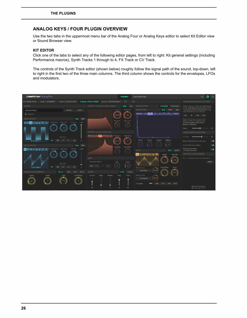
ANALOG KEYS / FOUR PLUGIN OVERVIEW
Use the two tabs in the uppermost menu bar of the Analog Four or Analog Keys editor to select Kit Editor view or Sound Browser view.
KIT EDITORClick one of the tabs to select any of the following editor pages, from left to right: Kit general settings (including Performance macros), Synth Tracks 1 through to 4, FX Track or CV Track.
The controls of the Synth Track editor (shown below) roughly follow the signal path of the sound, top-down, left to right in the first two of the three main columns. The third column shows the controls for the envelopes, LFOs and modulators.
26
THE PLUGINS
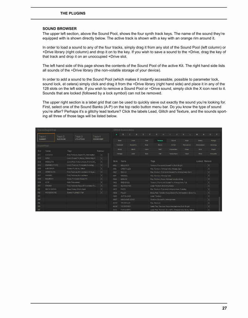
SOUND BROWSERThe upper left section, above the Sound Pool, shows the four synth track keys. The name of the sound they’re equipped with is shown directly below. The active track is shown with a key with an orange rim around it.
In order to load a sound to any of the four tracks, simply drag it from any slot of the Sound Pool (left column) or +Drive library (right column) and drop it on to the key. If you wish to save a sound to the +Drive, drag the key of that track and drop it on an unoccupied +Drive slot.
The left hand side of this page shows the contents of the Sound Pool of the active Kit. The right hand side lists all sounds of the +Drive library (the non-volatile storage of your device).
In order to add a sound to the Sound Pool (which makes it instantly accessible, possible to parameter lock, sound lock, et cetera) simply click and drag it from the +Drive library (right hand side) and place it in any of the 128 slots on the left side. If you wish to remove a Sound Pool or +Drive sound, simply click the X icon next to it. Sounds that are locked (followed by a lock symbol) can not be removed.
The upper right section is a label grid that can be used to quickly sieve out exactly the sound you’re looking for. First, select one of the Sound Banks (A-P) on the top radio button menu bar. Do you know the type of sound you’re after? Perhaps it’s a glitchy lead texture? Click the labels Lead, Glitch and Texture, and the sounds sport-ing all three of those tags will be listed below.
27
THE PLUGINS
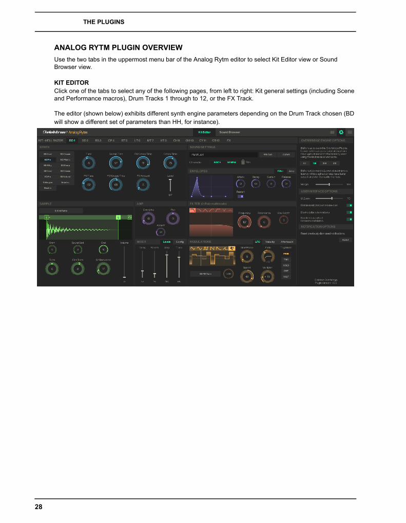
ANALOG RYTM PLUGIN OVERVIEW
Use the two tabs in the uppermost menu bar of the Analog Rytm editor to select Kit Editor view or Sound Browser view.
KIT EDITORClick one of the tabs to select any of the following pages, from left to right: Kit general settings (including Scene and Performance macros), Drum Tracks 1 through to 12, or the FX Track.
The editor (shown below) exhibits different synth engine parameters depending on the Drum Track chosen (BD will show a different set of parameters than HH, for instance).
28
THE PLUGINS
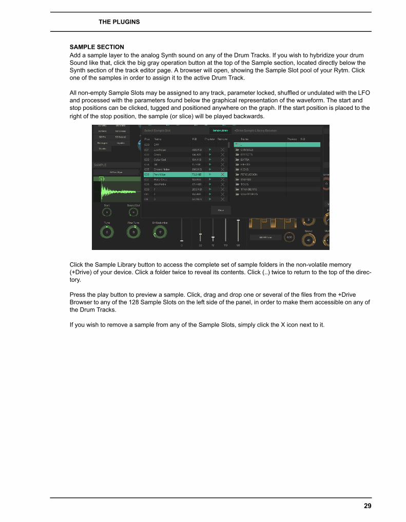
SAMPLE SECTIONAdd a sample layer to the analog Synth sound on any of the Drum Tracks. If you wish to hybridize your drum Sound like that, click the big gray operation button at the top of the Sample section, located directly below the Synth section of the track editor page. A browser will open, showing the Sample Slot pool of your Rytm. Click one of the samples in order to assign it to the active Drum Track.
All non-empty Sample Slots may be assigned to any track, parameter locked, shuffled or undulated with the LFO and processed with the parameters found below the graphical representation of the waveform. The start and stop positions can be clicked, tugged and positioned anywhere on the graph. If the start position is placed to the right of the stop position, the sample (or slice) will be played backwards.
Click the Sample Library button to access the complete set of sample folders in the non-volatile memory (+Drive) of your device. Click a folder twice to reveal its contents. Click (..) twice to return to the top of the direc-tory.
Press the play button to preview a sample. Click, drag and drop one or several of the files from the +Drive Browser to any of the 128 Sample Slots on the left side of the panel, in order to make them accessible on any of the Drum Tracks.
If you wish to remove a sample from any of the Sample Slots, simply click the X icon next to it.
29
THE PLUGINS
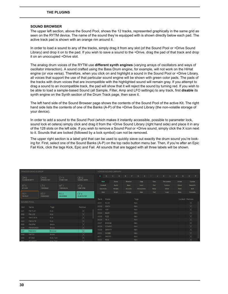
SOUND BROWSERThe upper left section, above the Sound Pool, shows the 12 tracks, represented graphically in the same grid as seen on the RYTM device. The name of the sound they’re equipped with is shown directly below each pad. The active track pad is shown with an orange rim around it.
In order to load a sound to any of the tracks, simply drag it from any slot (of the Sound Pool or +Drive Sound Library) and drop it on to the pad. If you wish to save a sound to the +Drive, drag the pad of that track and drop it on an unoccupied +Drive slot.
The analog drum voices of the RYTM use different synth engines (varying arrays of oscillators and ways of oscillator interaction). A sound crafted using the Bass Drum engine, for example, will not work on the HiHat engine (or vice versa). Therefore, when you click on and highlight a sound in the Sound Pool or +Drive Library, all voices that support the use of that particular sound engine will be shown with green color pads. The pads of the tracks with drum voices that are incompatible with the highlighted sound will remain gray. If you attempt to drag a sound to an incompatible track, the pad will show that it will reject the sound by turning red. If you wish to be able to load a sample-based Sound (all Sample, Filter, Amp and LFO settings) to any track, first disable its synth engine on the Synth section of the Drum Track page, then save it.
The left hand side of the Sound Browser page shows the contents of the Sound Pool of the active Kit. The right hand side lists the contents of one of the Banks (A-P) of the +Drive Sound Library (the non-volatile storage of your device).
In order to add a sound to the Sound Pool (which makes it instantly accessible, possible to parameter lock, sound lock et cetera) simply click and drag it from the +Drive Sound Library (right hand side) and place it in any of the 128 slots on the left side. If you wish to remove a Sound Pool or +Drive sound, simply click the X icon next to it. Sounds that are locked (followed by a lock symbol) can not be removed.
The upper right section is a label grid that can be used to quickly sieve out exactly the drum sound you’re look-ing for. First, select one of the Sound Banks (A-P) on the top radio button menu bar. Then, if you’re after an Epic Fail Kick, click the tags Kick, Epic and Fail. All sounds that are tagged with all three labels will be shown.
30
THE PLUGINS
INDIVIDUAL OUTPUTS
Note that in order to use individual audio inputs from your synth voices on the Overbridge plugin, you must acti-vate these channels as inputs on the Overbridge Control Panel (click the toggler button beneath a track).
All your Overbridge device tracks may be sequenced and automated using a DAW whether or not the individual tracks are activated or deactivated on the Control Panel, but in order to record audio from a track into the DAW, its channel must be activated.
Select the device you want to use for each instance of the plugin on the Machine Selection menu on the sidebar (click the device settings icon in the top right corner of the plugin window). This lets you use, for example, 2 Analog Fours (and access 8 analog synth voices) on your DAW.
If you’ve got the Analog Keys, Analog Four and Analog Rytm, all three of them Overbridge-enabled, you’ve got access to 16 awesome analog voices to craft, control, sequence and automate using your favorite DAW!
MULTIPLE OUTPUTS
The plugin exposes multiple audio outputs to the DAW. The first stereo channel is always the Main Out of the device. The remaining plugin output channels are the individual outputs from the synth or drum voices on your Elektron device.
SIDECHAIN INPUTS ROUTING
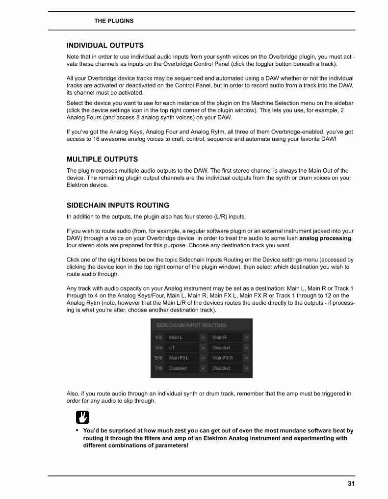
In addition to the outputs, the plugin also has four stereo (L/R) inputs.
If you wish to route audio (from, for example, a regular software plugin or an external instrument jacked into your DAW) through a voice on your Overbridge device, in order to treat the audio to some lush analog processing, four stereo slots are prepared for this purpose. Choose any destination track you want.
Click one of the eight boxes below the topic Sidechain Inputs Routing on the Device settings menu (accessed by clicking the device icon in the top right corner of the plugin window), then select which destination you wish to route audio through.
Any track with audio capacity on your Analog instrument may be set as a destination: Main L, Main R or Track 1 through to 4 on the Analog Keys/Four, Main L, Main R, Main FX L, Main FX R or Track 1 through to 12 on the Analog Rytm (note, however that the Main L/R of the devices routes the audio directly to the outputs - if process-ing is what you’re after, choose another destination track).
Also, if you route audio through an individual synth or drum track, remember that the amp must be triggered in order for any audio to slip through.
• You’d be surprised at how much zest you can get out of even the most mundane software beat by routing it through the filters and amp of an Elektron Analog instrument and experimenting with different combinations of parameters!
31
SEQUENCING WITH THE DIGITAL AUDIO WORKSTATION
SEQUENCING WITH THE DIGITAL AUDIO WORKSTATIONOnce an Overbridge plugin is loaded to your DAW project, you can send MIDI to the plugin in order to sequence your device. The MIDI channels are the same as the track numbers, so on the Analog Four / Analog Keys, you use MIDI channels 1 through 4 for sequencing the tracks. For the Rytm, channels 1 through 12 are used.
If you wish to record streaming audio from your Overbridge device into DAW tracks, or send audio from your DAW for processing on your Overbridge device, your DAW must be configured accordingly (see “Appendix B: Setup Example“ on how to do the initial configuration).
SYNCING THE ELEKTRON SEQUENCER
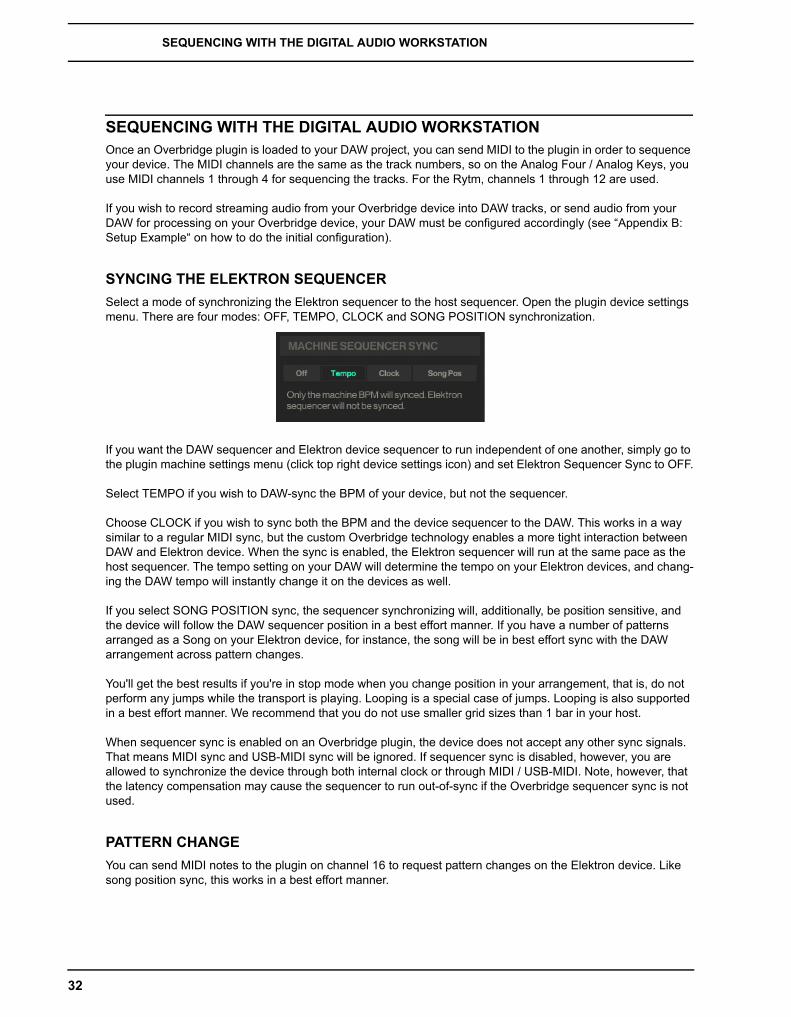
Select a mode of synchronizing the Elektron sequencer to the host sequencer. Open the plugin device settings menu. There are four modes: OFF, TEMPO, CLOCK and SONG POSITION synchronization.
If you want the DAW sequencer and Elektron device sequencer to run independent of one another, simply go to the plugin machine settings menu (click top right device settings icon) and set Elektron Sequencer Sync to OFF.
Select TEMPO if you wish to DAW-sync the BPM of your device, but not the sequencer.
Choose CLOCK if you wish to sync both the BPM and the device sequencer to the DAW. This works in a way similar to a regular MIDI sync, but the custom Overbridge technology enables a more tight interaction between DAW and Elektron device. When the sync is enabled, the Elektron sequencer will run at the same pace as the host sequencer. The tempo setting on your DAW will determine the tempo on your Elektron devices, and chang-ing the DAW tempo will instantly change it on the devices as well.
If you select SONG POSITION sync, the sequencer synchronizing will, additionally, be position sensitive, and the device will follow the DAW sequencer position in a best effort manner. If you have a number of patterns arranged as a Song on your Elektron device, for instance, the song will be in best effort sync with the DAW arrangement across pattern changes.
You'll get the best results if you're in stop mode when you change position in your arrangement, that is, do not perform any jumps while the transport is playing. Looping is a special case of jumps. Looping is also supported in a best effort manner. We recommend that you do not use smaller grid sizes than 1 bar in your host.
When sequencer sync is enabled on an Overbridge plugin, the device does not accept any other sync signals. That means MIDI sync and USB-MIDI sync will be ignored. If sequencer sync is disabled, however, you are allowed to synchronize the device through both internal clock or through MIDI / USB-MIDI. Note, however, that the latency compensation may cause the sequencer to run out-of-sync if the Overbridge sequencer sync is not used.
PATTERN CHANGE
You can send MIDI notes to the plugin on channel 16 to request pattern changes on the Elektron device. Like song position sync, this works in a best effort manner.
32
CREDITS AND CONTACT INFORMATION
CREDITS AND CONTACT INFORMATION
CREDITS
OVERBRIDGE DESIGN AND DEVELOPMENTOscar AlbinssonOscar DragénMagnus ForsellAnders GärderJimmy MyhrmanJon MårtenssonDavid ReveljMattias RickardssonDaniel Troberg
ADDITIONAL DESIGNUfuk DemirThomas Ekelund
TESTINGSimon MattissonMartin MellströmOlle PeterssonCenk Sayinli
MANUALUfuk DemirTobias EinarssonThomas EkelundAnders GärderSimon MattissonDaniel Sterner
CONTACT INFORMATION
ELEKTRON WEBSITEwww.elektron.se
OFFICE ADDRESSElektron Music Machines MAV ABSockerbruket 9SE-414 51 GothenburgSweden
TELEPHONE+46 31 743 744 0
33

CREDITS AND CONTACT INFORMATION
34
Appendix A: Media Resources
You will find some useful Overbridge-related media below. Presentation videos, workflow videos and manu-als.
Clicking on the links below will bring you to the corresponding item, provided you have an inter-net connection and a web browser.
INTRODUCTORY VIDEOS
Overbridge
Analog Four
Analog Keys
Analog Rytm
WORKFLOW VIDEOS
Overbridge
Analog Keys / Analog Four
Analog Rytm
MANUALS
Analog Four
Analog Keys
Analog Rytm
Appendix A: Media Resources A-1

A-2 Appendix A: Media Resources

Appendix B: Setup Example
This appendix shows a step-by-step setting up of the Overbridge plugins in Ableton Live. Make sure Over-bridge has been installed according to the manual (see “INSTALLING OVERBRIDGE” on page 6) before proceeding with the setup example shown below.
ABLETON STEP ONE - INSERT PLUGIN
First off, open the Overbridge Control Panel and enable the individual outputs. Then open a new Ableton Live Set, create a new MIDI track and insert the Overbridge plugin.
B-1
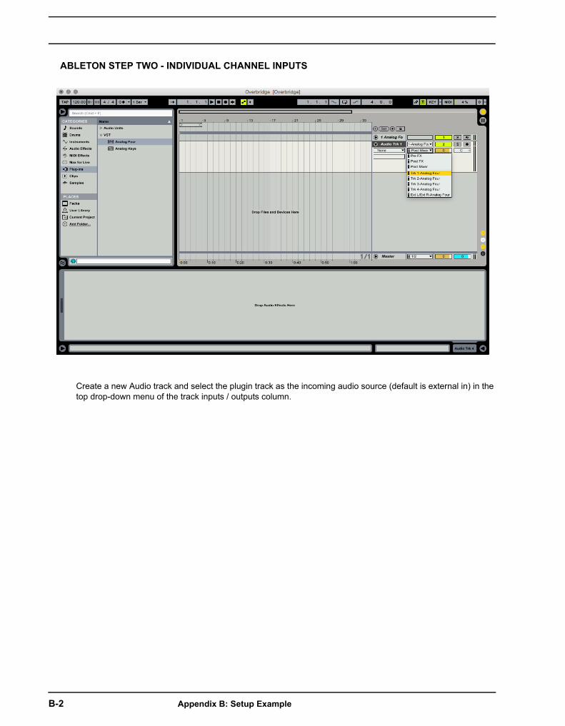
ABLETON STEP TWO - INDIVIDUAL CHANNEL INPUTS
Create a new Audio track and select the plugin track as the incoming audio source (default is external in) in the top drop-down menu of the track inputs / outputs column.
B-2 Appendix B: Setup Example

ABLETON STEP THREE - AUDIO CHANNEL OUTPUTS
Select the first track of outbound audio from the plugin in the second drop-down menu. Track 1 is labeled Trk 1, Track 2 is called Trk 2 and so on. Repeat the procedure for the rest of the individual outputs of the plugin.
Appendix B: Setup Example B-3
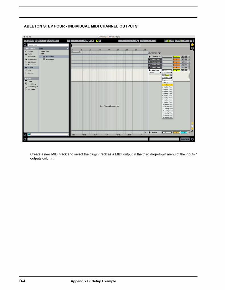
ABLETON STEP FOUR - INDIVIDUAL MIDI CHANNEL OUTPUTS
Create a new MIDI track and select the plugin track as a MIDI output in the third drop-down menu of the inputs / outputs column.
B-4 Appendix B: Setup Example
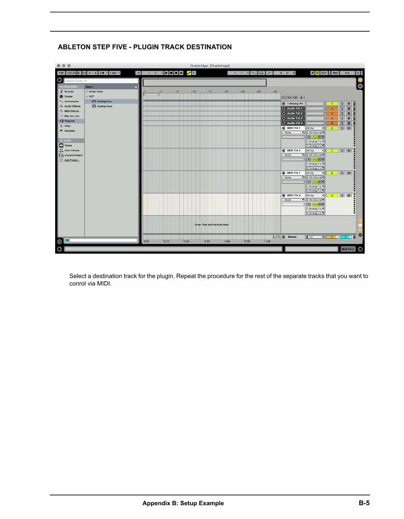
ABLETON STEP FIVE - PLUGIN TRACK DESTINATION
Select a destination track for the plugin. Repeat the procedure for the rest of the separate tracks that you want to conrol via MIDI.
Appendix B: Setup Example B-5

ABLETON STEP SIX - DELAY COMPENSATION
Make sure Delay Compensation is enabled. It is found at Options in the top menu bar.
B-6 Appendix B: Setup Example
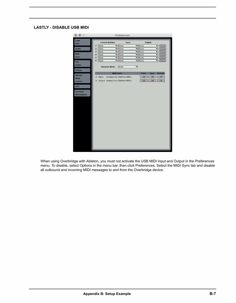
LASTLY - DISABLE USB MIDI
When using Overbridge with Ableton, you must not activate the USB MIDI Input and Output in the Preferences menu. To disable, select Options in the menu bar, then click Preferences. Select the MIDI Sync tab and disable all outbound and incoming MIDI messages to and from the Overbridge device.
Appendix B: Setup Example B-7

B-8 Appendix B: Setup Example

INDEX
AAUDIO INTERFACE 9
CCHANNEL TABLE 10
ANALOG KEYS / FOUR 10
ANALOG RYTM 10
CONTROL PANEL 3AUDIO I/O 12
LAYOUT 3MATCHING PROTOCOLS 11
SETUP 11
IINDIVIDUAL OUTPUTS 31
INPUT AUDIO ROUTING 31
INSTALLING 6MAC OS X 7WINDOWS 6
OOVERBRIDGE SUITE 2
PPLUGIN 18
ANALOG KEYS/FOUR 26
ANALOG RYTM 28
BUFFER SIZE 30
CONTROL ELEMENTS AND INDICATORS 19
GENERAL CONTROLS 18
MACHINE STATE RECALL 23
MIDI 22
OUTPUTS 31
PARAMETER AUTOMATION 22
QUICK ASSIGN 24
QQUICK START 5
RRECALL 23
SSAMPLE MANAGEMENT 29
SEQUENCER 32
PATTERN CHANGE 32
SYNC MODES 32
UUNINSTALLING
MAC OS X 7WINDOWS 7
VVST LOCATIONS 7
INDEX 1

2 INDEX