Service Letter SL2017-644/JERA Action code: WHEN CONVENIENT Michael Petersen Vice President PrimeServ Two-stroke Henrik Birkegård Senior Manager Technical Service Head office (& postal address) MAN Diesel & Turbo Teglholmsgade 41 2450 Copenhagen SV Denmark Phone: +45 33 85 11 00 Fax: +45 33 85 10 30 [email protected]www.mandieselturbo.com PrimeServ Teglholmsgade 41 2450 Copenhagen SV Denmark Phone: +45 33 85 11 00 Fax: +45 33 85 10 49 [email protected]Production Teglholmsgade 35 2450 Copenhagen SV Denmark Phone: +45 33 85 11 00 Fax: +45 33 85 10 17 [email protected]Forwarding & Receiving Teglholmsgade 35 2450 Copenhagen SV Denmark Phone: +45 33 85 11 00 Fax: +45 33 85 10 16 [email protected]MAN Diesel & Turbo Branch of MAN Diesel & Turbo SE, Germany CVR No.: 31611792 Head office: Teglholmsgade 41 2450 Copenhagen SV, Denmark German Reg.No.: HRB 22056 Amtsgericht Augsburg Dear Sirs This service letter provides recommendations on a detailed overhaul strategy, monitoring and update of the ME specific components of MAN B&W two-stroke engines (ME/ME-C and ME-B) based on ap- proximately 10 years of service experience. The aim is to facilitate planning and implementation of available up- grades with focus on areas primarily related to 5-year dockings. The service letter also includes recommendations on overhauls and in- spections to be done in service outside the 5-year docking intervals. Yours faithfully Overhaul Strategy ME/ME-C and ME-B Engines ME specific components SL2017-644/JERA March 2017 Concerns Owners and operators of MAN B&W two-stroke marine diesel engines. Type: ME/ME-C and ME-B Summary Recommendations on a detailed over- haul strategy, monitoring and update of the ME specific components of MAN B&W two-stroke engines are given based on approximately 10 years of service experience. References are made to SL2015-609 and SL2017-643.
Transcript
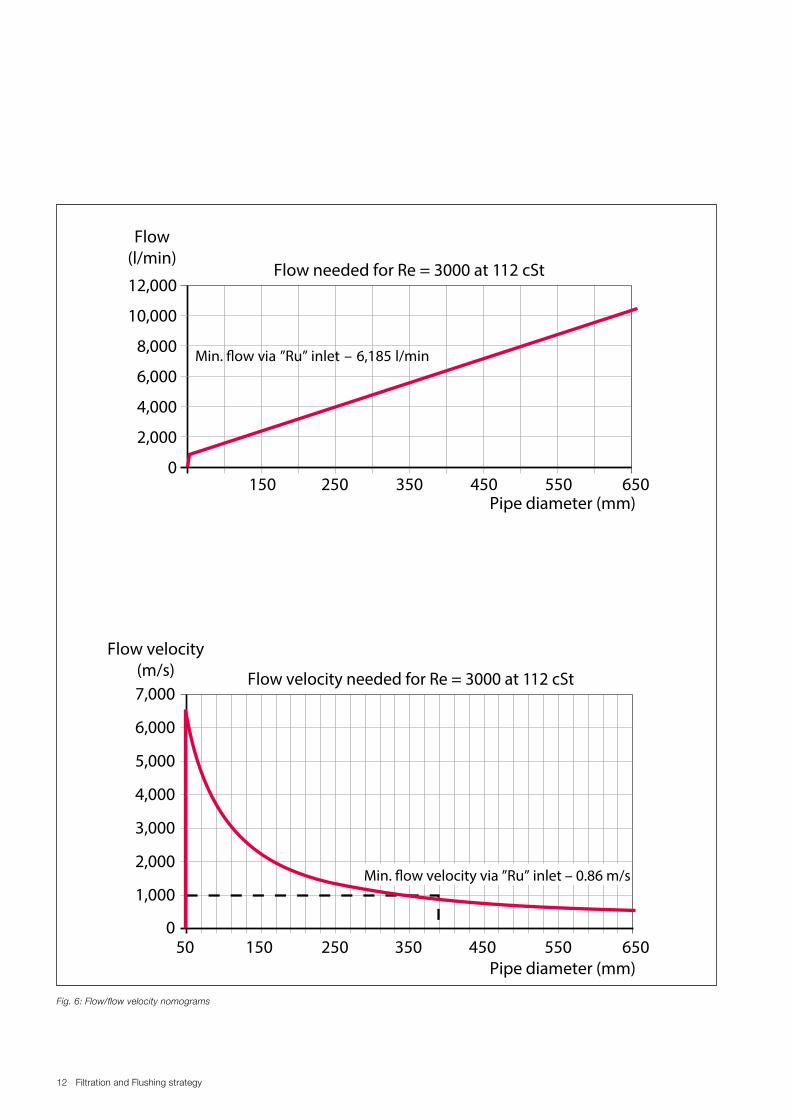
Service Letter SL2017-644/JERA
Action code: WHEN CONVENIENT
Michael PetersenVice President PrimeServ Two-stroke
MAN Diesel & TurboBranch of MAN Diesel & Turbo SE, GermanyCVR No.: 31611792Head office: Teglholmsgade 412450 Copenhagen SV, DenmarkGerman Reg.No.: HRB 22056Amtsgericht Augsburg
Dear Sirs
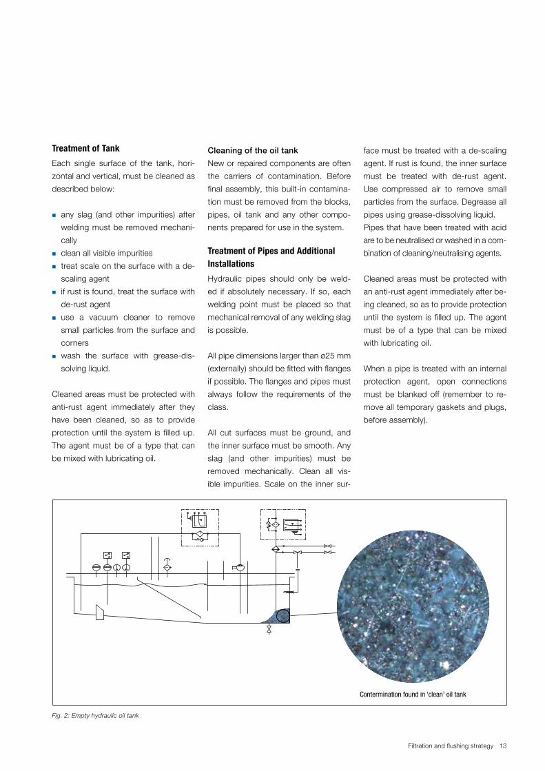
This service letter provides recommendations on a detailed overhaul strategy, monitoring and update of the ME specific components of MAN B&W two-stroke engines (ME/ME-C and ME-B) based on ap-proximately 10 years of service experience.
The aim is to facilitate planning and implementation of available up-grades with focus on areas primarily related to 5-year dockings. The service letter also includes recommendations on overhauls and in-spections to be done in service outside the 5-year docking intervals.
Yours faithfully
Overhaul Strategy ME/ME-C and ME-B Engines ME specific components
SL2017-644/JERAMarch 2017
ConcernsOwners and operators of MAN B&W two-stroke marine diesel engines.Type: ME/ME-C and ME-B
SummaryRecommendations on a detailed over-haul strategy, monitoring and update of the ME specific components of MAN B&W two-stroke engines are given based on approximately 10 years of service experience.
References are made to SL2015-609 and SL2017-643.
Service Letter SL2017-644/JERA
Overhaul Strategy ME/ME-C and ME-B Engines and control systems. Page 2 of 8 pages
Content:Engine control system software version ............................2Hydraulics ........................................................................2 Electric motors for electrically driven pumps .................2 Hydraulic pumps ..........................................................2Hydraulic cylinder unit .......................................................2 Fuel oil pressure booster ..............................................2 Exhaust valve actuator .................................................3 Non-return valve of exhaust valve actuator .............5 Hydraulic control valves (FIVA/ELVA/ELFI) .....................5 Accumulator .................................................................6System and hydraulic oil cleanliness .................................6 Superfine filter ..................................................................7
Engine control system software version Recommended software versions:ME: 0905 or higherME-B: 0906 or higher
It is recommended that ME engines operating with engine control system (ECS) software versions 0510 or lower are upgraded to version 0905 or higher when it is convenient, typically during dry dock.
The upgrade primarily offers improved troubleshootingassistance provided by a main operating panel (MOP) inter-face assisting the crew on board.
Any ME engine can be upgraded to a higher software ver-sion in order to improve the troubleshooting assistance. However, this would be carried out as a normal payment job.
HydraulicsElectric motors for electrically driven pumpsFor information about the expected lifetime of electric mo-tors and bearings, please consult the makers’ guidelines. Electric motors are typically defined for a lifetime of 32,000 running hours (R/H).
Omission of regular maintenance of these pumps can result in:
• damage to pump elements, typically the bearings• limited propulsion power• damage to hydraulic components in the hydraulic cylin-
der unit (HCU) and fuel injection valve actuation (FIVA).
For further details and recommendations on engine driven hydraulic pumps, see SL2015-609.
Hydraulic cylinder unit Fuel oil pressure boosterRecommended overhaul and replacement intervals (SL2017-643):
• overhaul of suction valve: 8,000 R/H• replacement of suction valve: 32,000 R/H• overhaul of complete fuel oil pressure booster: 32,000 R/H.
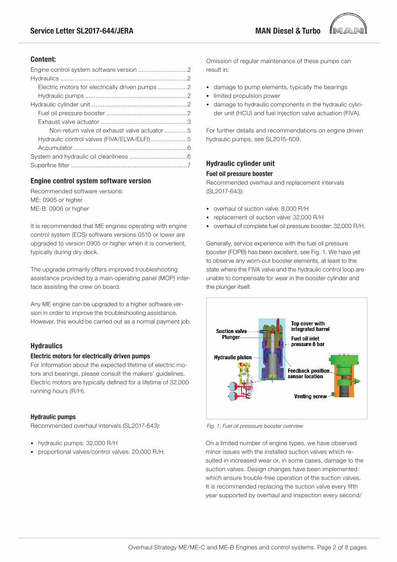
Generally, service experience with the fuel oil pressure booster (FOPB) has been excellent, see Fig. 1. We have yet to observe any worn-out booster elements, at least to the state where the FIVA valve and the hydraulic control loop are unable to compensate for wear in the booster cylinder and the plunger itself.
Fig. 1: Fuel oil presssure booster overview
On a limited number of engine types, we have observed minor issues with the installed suction valves which re-sulted in increased wear or, in some cases, damage to the suction valves. Design changes have been implemented which ensure trouble-free operation of the suction valves. It is recommended replacing the suction valve every fifth year supported by overhaul and inspection every second/
Service Letter SL2017-644/JERA
Overhaul Strategy ME/ME-C and ME-B Engines and control systems. Page 3 of 8 pages
third year based on the number of running hours as previ-ously mentioned.
Furthermore, it is recommended overhauling the FOPB completely every fifth year (32,000 R/H). This includes changing the seals on both the fuel oil side and the hy-draulic oil side. During the overhaul it is also recommended checking the running surfaces of the plunger/barrel and the connection between the umbrella and the plunger. Fig. 2 shows the top cover and the umbrella mounted on the plunger.
It is recommended inspecting the high-pressure pipe with focus on the general condition of the sealing surface in or-der to ensure correct seating and minimise the risk of fuel oil leakages, see Fig. 3.
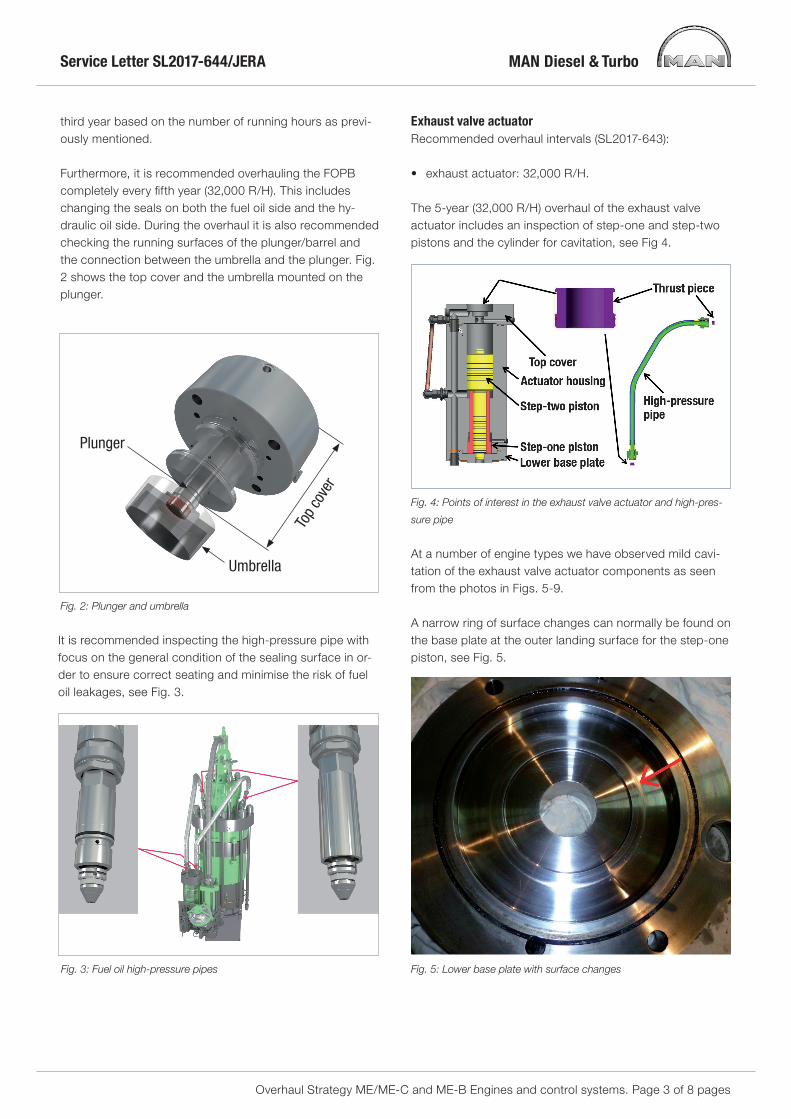
The 5-year (32,000 R/H) overhaul of the exhaust valve actuator includes an inspection of step-one and step-two pistons and the cylinder for cavitation, see Fig 4.
Fig. 4: Points of interest in the exhaust valve actuator and high-pres-
sure pipe
At a number of engine types we have observed mild cavi-tation of the exhaust valve actuator components as seen from the photos in Figs. 5-9.
A narrow ring of surface changes can normally be found on the base plate at the outer landing surface for the step-one piston, see Fig. 5.
Fig. 5: Lower base plate with surface changes
Service Letter SL2017-644/JERA
Overhaul Strategy ME/ME-C and ME-B Engines and control systems. Page 4 of 8 pages
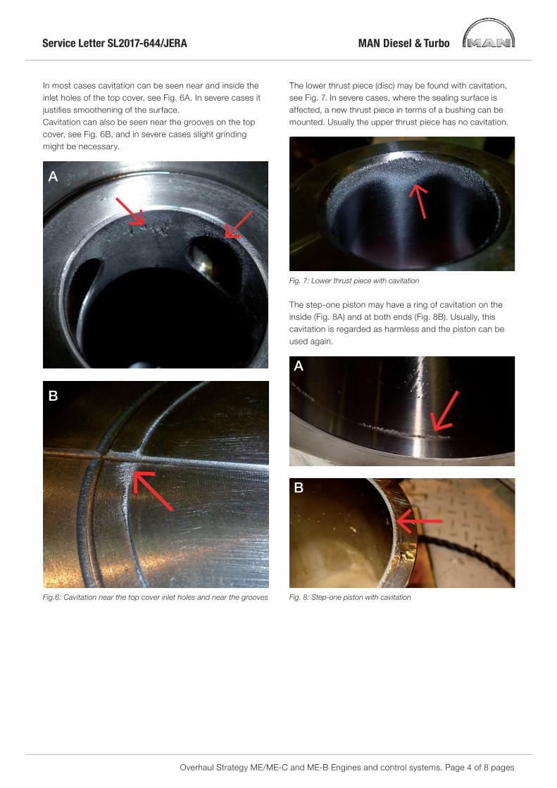
In most cases cavitation can be seen near and inside the inlet holes of the top cover, see Fig. 6A. In severe cases it justifies smoothening of the surface. Cavitation can also be seen near the grooves on the top cover, see Fig. 6B, and in severe cases slight grinding might be necessary.
A
B
Fig.6: Cavitation near the top cover inlet holes and near the grooves
The lower thrust piece (disc) may be found with cavitation, see Fig. 7. In severe cases, where the sealing surface is affected, a new thrust piece in terms of a bushing can be mounted. Usually the upper thrust piece has no cavitation.
Fig. 7: Lower thrust piece with cavitation
The step-one piston may have a ring of cavitation on the inside (Fig. 8A) and at both ends (Fig. 8B). Usually, this cavitation is regarded as harmless and the piston can be used again.
A
B
Fig. 8: Step-one piston with cavitation
Service Letter SL2017-644/JERA
Overhaul Strategy ME/ME-C and ME-B Engines and control systems. Page 5 of 8 pages
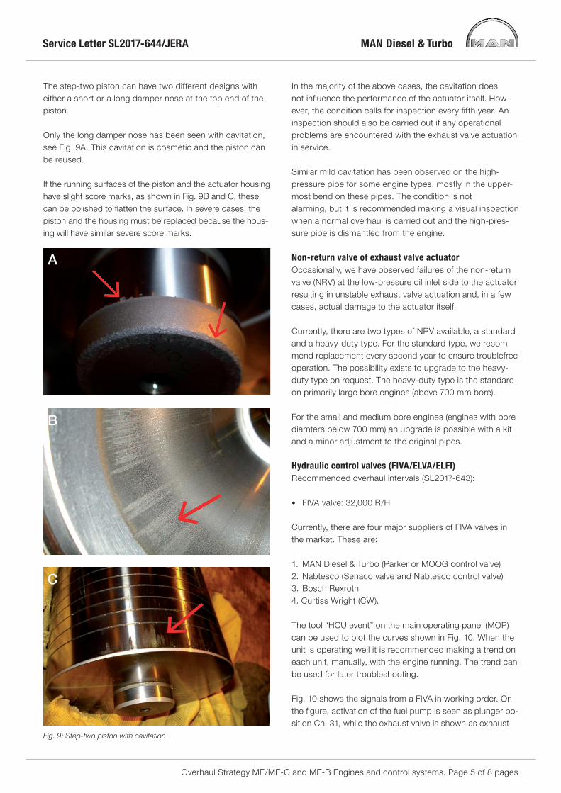
The step-two piston can have two different designs with either a short or a long damper nose at the top end of the piston.
Only the long damper nose has been seen with cavitation, see Fig. 9A. This cavitation is cosmetic and the piston can be reused.
If the running surfaces of the piston and the actuator housing have slight score marks, as shown in Fig. 9B and C, these can be polished to flatten the surface. In severe cases, the piston and the housing must be replaced because the hous-ing will have similar severe score marks.
A
B
C
Fig. 9: Step-two piston with cavitation
In the majority of the above cases, the cavitation does not influence the performance of the actuator itself. How-ever, the condition calls for inspection every fifth year. An inspection should also be carried out if any operational problems are encountered with the exhaust valve actuation in service.
Similar mild cavitation has been observed on the high-pressure pipe for some engine types, mostly in the upper-most bend on these pipes. The condition is notalarming, but it is recommended making a visual inspection when a normal overhaul is carried out and the high-pres-sure pipe is dismantled from the engine.
Non-return valve of exhaust valve actuatorOccasionally, we have observed failures of the non-return valve (NRV) at the low-pressure oil inlet side to the actuator resulting in unstable exhaust valve actuation and, in a few cases, actual damage to the actuator itself.
Currently, there are two types of NRV available, a standard and a heavy-duty type. For the standard type, we recom-mend replacement every second year to ensure troublefree operation. The possibility exists to upgrade to the heavy-duty type on request. The heavy-duty type is the standard on primarily large bore engines (above 700 mm bore).
For the small and medium bore engines (engines with bore diamters below 700 mm) an upgrade is possible with a kit and a minor adjustment to the original pipes.
Hydraulic control valves (FIVA/ELVA/ELFI)Recommended overhaul intervals (SL2017-643):
• FIVA valve: 32,000 R/H
Currently, there are four major suppliers of FIVA valves in the market. These are:
1. MAN Diesel & Turbo (Parker or MOOG control valve)2. Nabtesco (Senaco valve and Nabtesco control valve)3. Bosch Rexroth4. Curtiss Wright (CW).
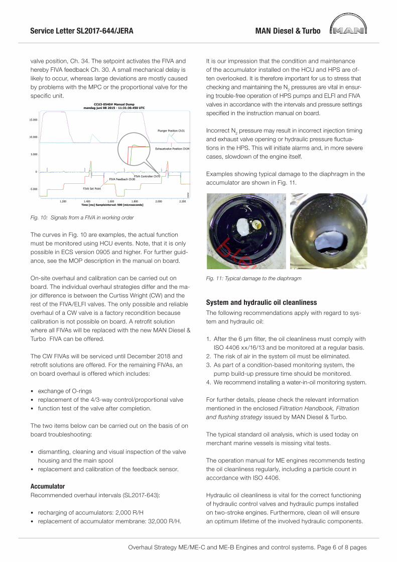
The tool “HCU event” on the main operating panel (MOP) can be used to plot the curves shown in Fig. 10. When the unit is operating well it is recommended making a trend on each unit, manually, with the engine running. The trend can be used for later troubleshooting.
Fig. 10 shows the signals from a FIVA in working order. On the figure, activation of the fuel pump is seen as plunger po-sition Ch. 31, while the exhaust valve is shown as exhaust
Service Letter SL2017-644/JERA
Overhaul Strategy ME/ME-C and ME-B Engines and control systems. Page 6 of 8 pages
valve position, Ch. 34. The setpoint activates the FIVA and hereby FIVA feedback Ch. 30. A small mechanical delay is likely to occur, whereas large deviations are mostly caused by problems with the MPC or the proportional valve for the specific unit.
Fig. 10: Signals from a FIVA in working order
The curves in Fig. 10 are examples, the actual function must be monitored using HCU events. Note, that it is only possible in ECS version 0905 and higher. For further guid-ance, see the MOP description in the manual on board.
On-site overhaul and calibration can be carried out on board. The individual overhaul strategies differ and the ma-jor difference is between the Curtiss Wright (CW) and the rest of the FIVA/ELFI valves. The only possible and reliable overhaul of a CW valve is a factory recondition because calibration is not possible on board. A retrofit solution where all FIVAs will be replaced with the new MAN Diesel & Turbo FIVA can be offered.
The CW FIVAs will be serviced until December 2018 and retrofit solutions are offered. For the remaining FIVAs, an on board overhaul is offered which includes:
• exchange of O-rings• replacement of the 4/3-way control/proportional valve• function test of the valve after completion.
The two items below can be carried out on the basis of on board troubleshooting: • dismantling, cleaning and visual inspection of the valve
housing and the main spool• replacement and calibration of the feedback sensor.
• recharging of accumulators: 2,000 R/H• replacement of accumulator membrane: 32,000 R/H.
It is our impression that the condition and maintenance of the accumulator installed on the HCU and HPS are of-ten overlooked. It is therefore important for us to stress that checking and maintaining the N2 pressures are vital in ensur-ing trouble-free operation of HPS pumps and ELFI and FIVA valves in accordance with the intervals and pressure settings specified in the instruction manual on board.
Incorrect N2 pressure may result in incorrect injection timing and exhaust valve opening or hydraulic pressure fluctua-tions in the HPS. This will initiate alarms and, in more severe cases, slowdown of the engine itself.
Examples showing typical damage to the diaphragm in the accumulator are shown in Fig. 11.
Fig. 11: Typical damage to the diaphragm
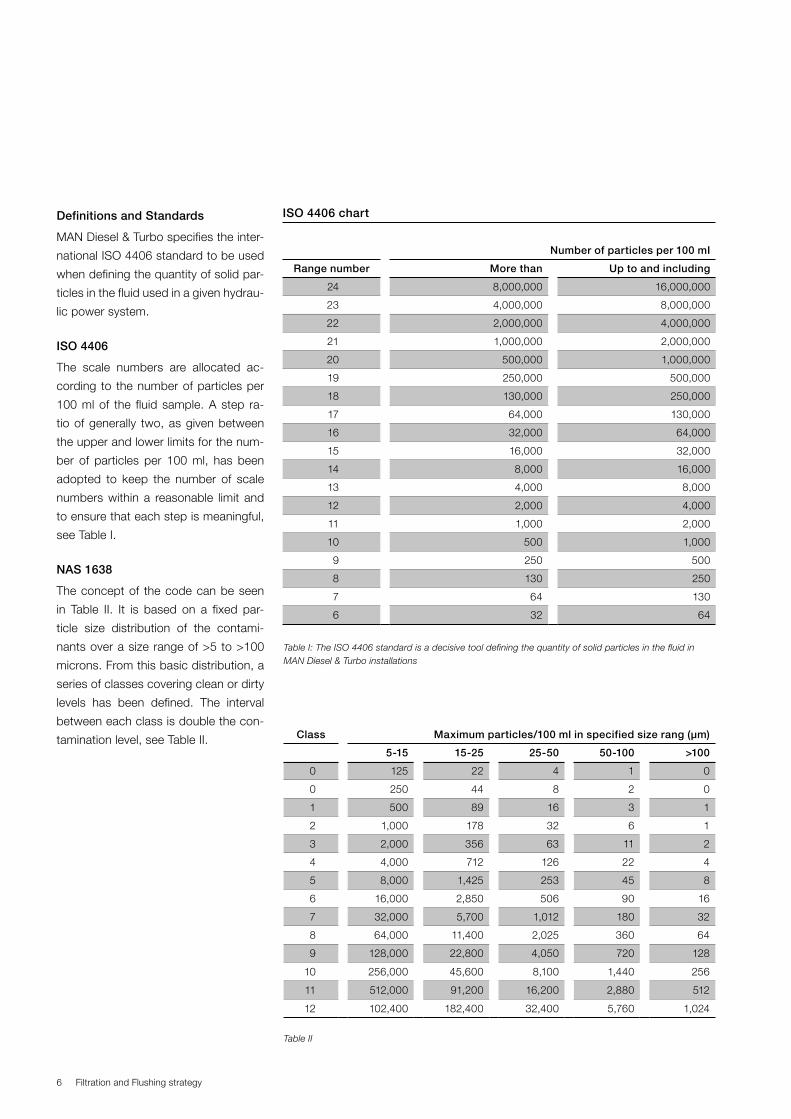
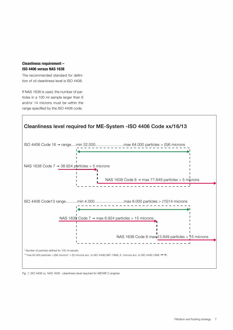
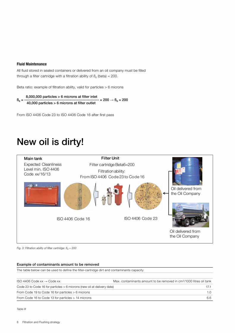
System and hydraulic oil cleanlinessThe following recommendations apply with regard to sys-tem and hydraulic oil:
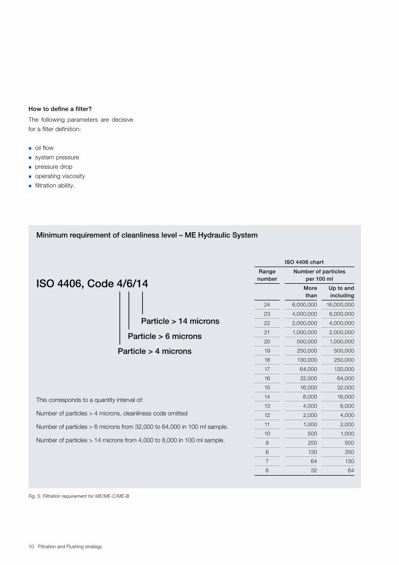
1. After the 6 μm filter, the oil cleanliness must comply with ISO 4406 xx/16/13 and be monitored at a regular basis.
2. The risk of air in the system oil must be eliminated.3. As part of a condition-based monitoring system, the
pump build-up pressure time should be monitored.4. We recommend installing a water-in-oil monitoring system.
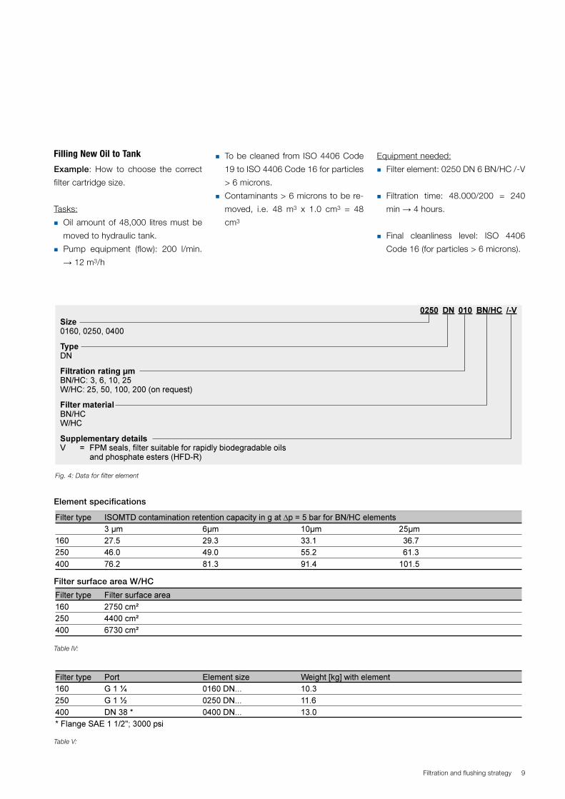
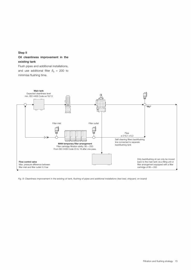
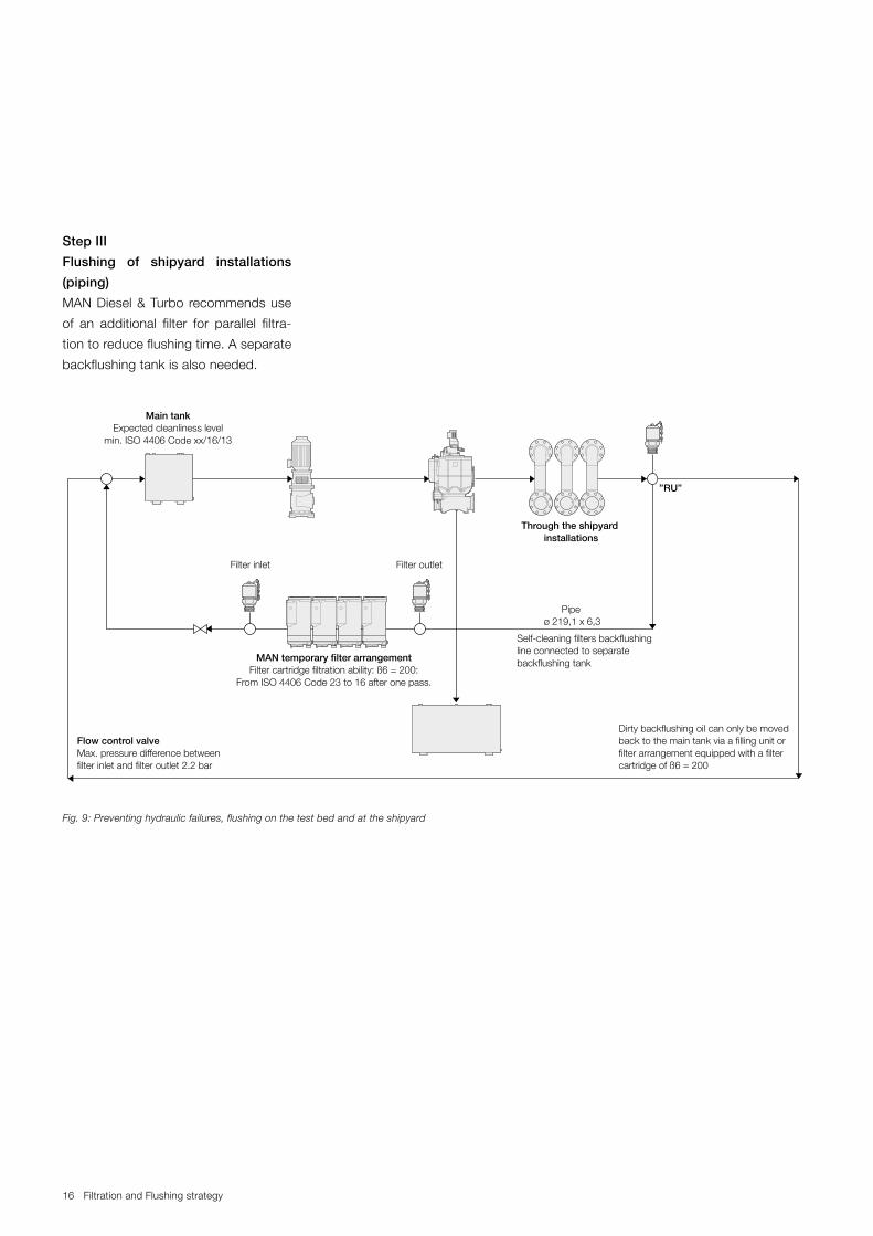
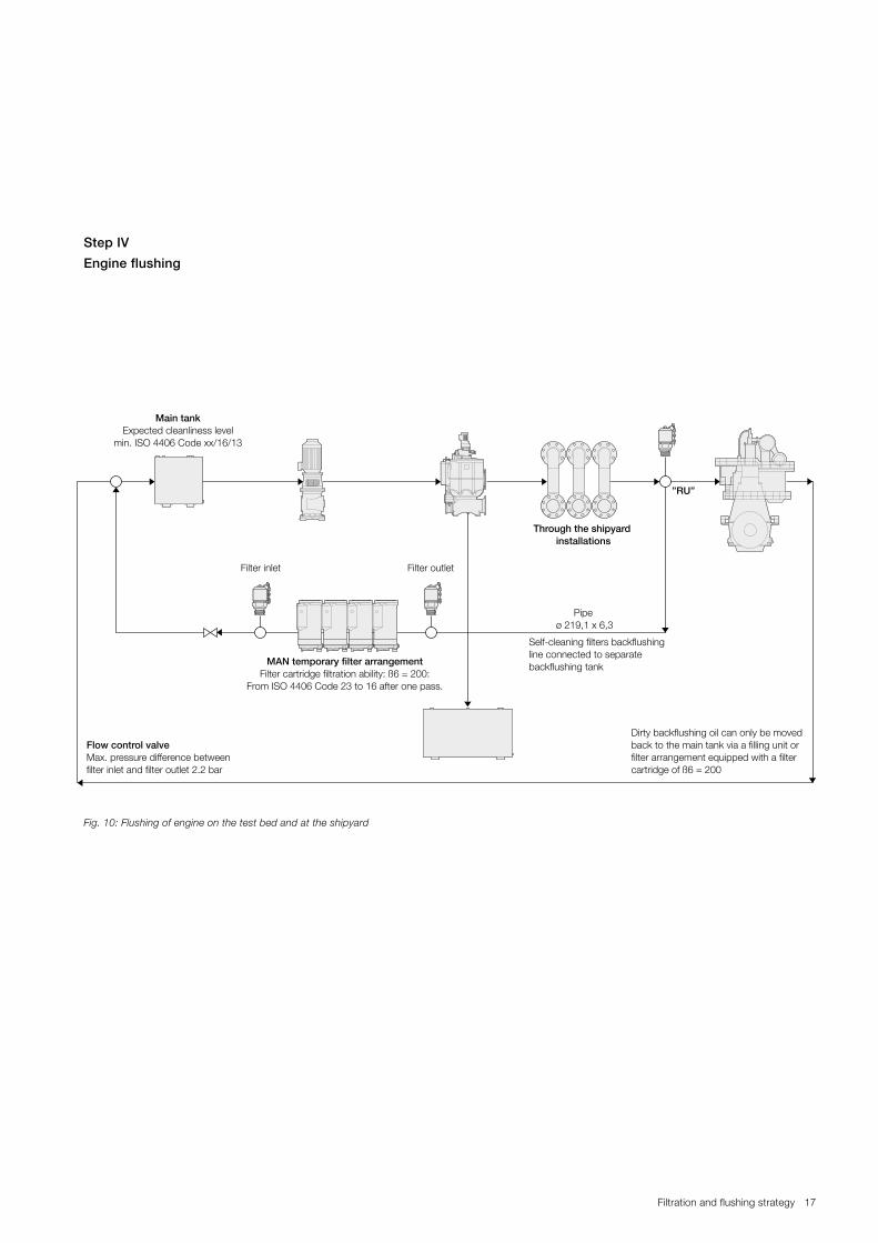
For further details, please check the relevant information mentioned in the enclosed Filtration Handbook, Filtration and flushing strategy issued by MAN Diesel & Turbo.
The typical standard oil analysis, which is used today on merchant marine vessels is missing vital tests.
The operation manual for ME engines recommends testing the oil cleanliness regularly, including a particle count in accordance with ISO 4406.
Hydraulic oil cleanliness is vital for the correct functioning of hydraulic control valves and hydraulic pumps installed on two-stroke engines. Furthermore, clean oil will ensure an optimum lifetime of the involved hydraulic components.
CCU3-0540# Manual Dumpmandag juni 08 2015 - 11:31:30.450 UTC
Overhaul Strategy ME/ME-C and ME-B Engines and control systems. Page 7 of 8 pages
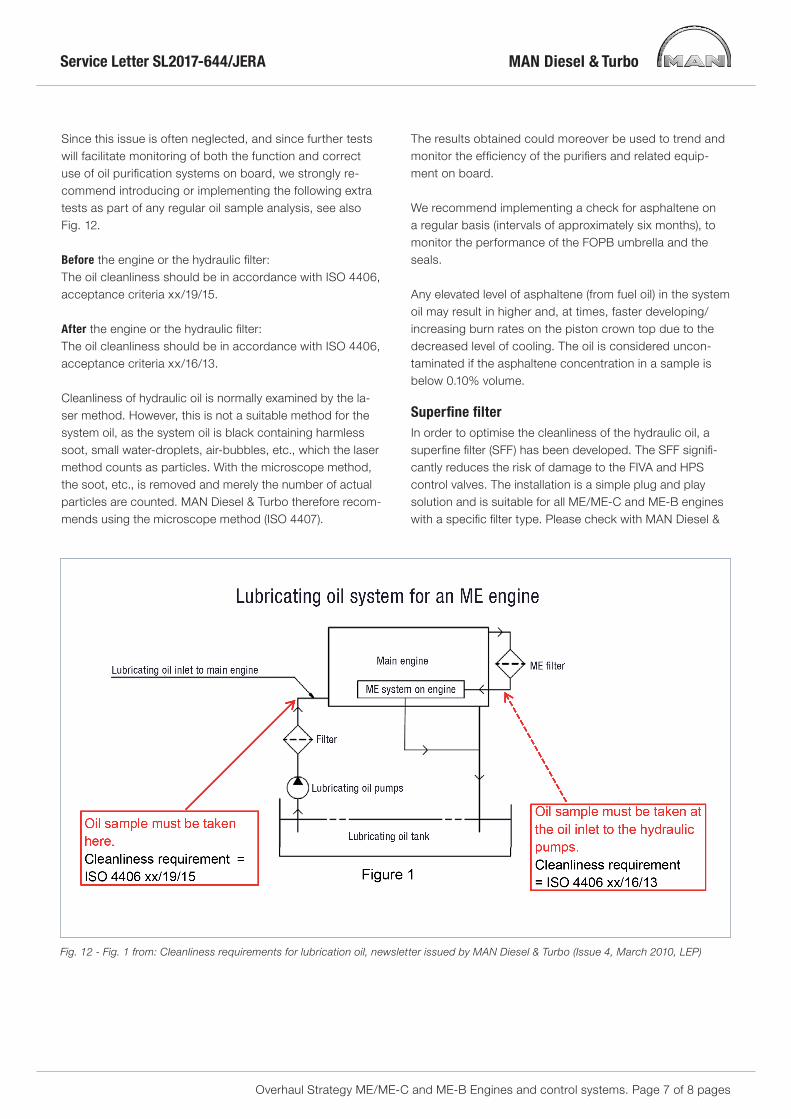
Since this issue is often neglected, and since further tests will facilitate monitoring of both the function and correct use of oil purification systems on board, we strongly re-commend introducing or implementing the following extra tests as part of any regular oil sample analysis, see also Fig. 12.
Before the engine or the hydraulic filter:The oil cleanliness should be in accordance with ISO 4406, acceptance criteria xx/19/15.
After the engine or the hydraulic filter:The oil cleanliness should be in accordance with ISO 4406, acceptance criteria xx/16/13.
Cleanliness of hydraulic oil is normally examined by the la-ser method. However, this is not a suitable method for the system oil, as the system oil is black containing harmless soot, small water-droplets, air-bubbles, etc., which the laser method counts as particles. With the microscope method, the soot, etc., is removed and merely the number of actual particles are counted. MAN Diesel & Turbo therefore recom-mends using the microscope method (ISO 4407).
The results obtained could moreover be used to trend and monitor the efficiency of the purifiers and related equip-ment on board.
We recommend implementing a check for asphaltene on a regular basis (intervals of approximately six months), to monitor the performance of the FOPB umbrella and the seals. Any elevated level of asphaltene (from fuel oil) in the system oil may result in higher and, at times, faster developing/increasing burn rates on the piston crown top due to the decreased level of cooling. The oil is considered uncon-taminated if the asphaltene concentration in a sample is below 0.10% volume.
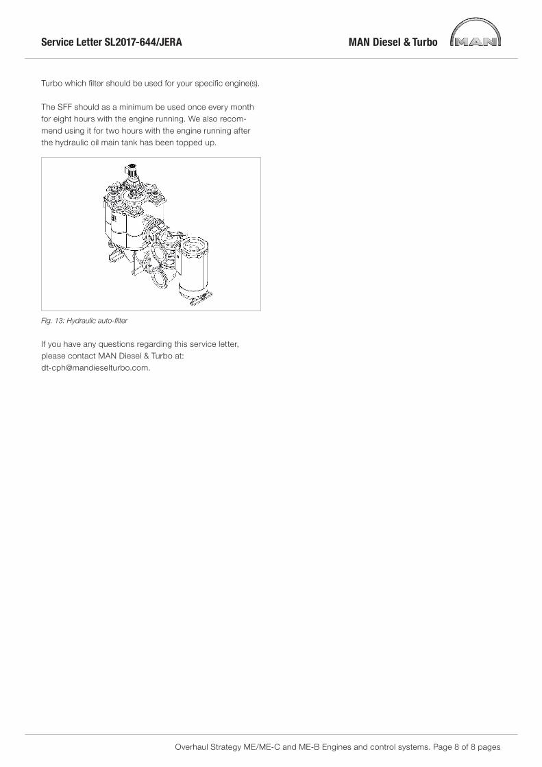
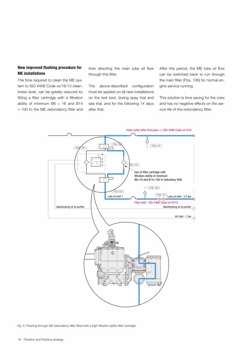
Superfine filterIn order to optimise the cleanliness of the hydraulic oil, a superfine filter (SFF) has been developed. The SFF signifi-cantly reduces the risk of damage to the FIVA and HPS control valves. The installation is a simple plug and play solution and is suitable for all ME/ME-C and ME-B engines with a specific filter type. Please check with MAN Diesel &
Fig. 12 - Fig. 1 from: Cleanliness requirements for lubrication oil, newsletter issued by MAN Diesel & Turbo (Issue 4, March 2010, LEP)
Service Letter SL2017-644/JERA
Overhaul Strategy ME/ME-C and ME-B Engines and control systems. Page 8 of 8 pages
Turbo which filter should be used for your specific engine(s).
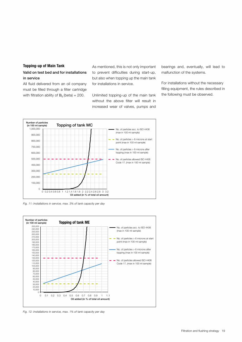
The SFF should as a minimum be used once every month for eight hours with the engine running. We also recom-mend using it for two hours with the engine running after the hydraulic oil main tank has been topped up.
Fig. 13: Hydraulic auto-filter
If you have any questions regarding this service letter, please contact MAN Diesel & Turbo at: [email protected].
1.10 0.1 0.2 0.3 0.4 0.5 0.6 0.7 0.8 0.9 1Oil added (in % of total oil amount)
No. of particles acc. to ISO 4406(max in 100 ml sample)
No. of particles > 6 microns at startpoint (max in 100 ml sample)
No. of particles > 6 microns aftertopping (max in 100 ml sample)
No. of particles allowed ISO 4406Code 17, (max in 100 ml sample)
Topping of tank ME
Fig. 12: Installations in service, max. 1% of tank capacity per day
20 Filtration and Flushing strategy
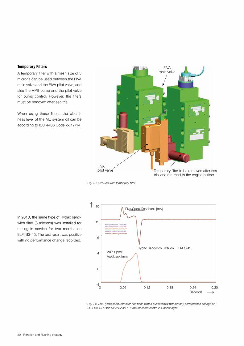
Temporary Filters
A temporary filter with a mesh size of 3
microns can be used between the FIVA
main valve and the FIVA pilot valve, and
also the HPS pump and the pilot valve
for pump control. However, the filters
must be removed after sea trial.
When using these filters, the cleanli-
ness level of the ME system oil can be
according to ISO 4406 Code xx/17/14.
In 2010, the same type of Hydac sand-
wich filter (3 microns) was installed for
testing in service for two months on
ELFI B3-45. The test result was positive
with no performance change recorded.
FIVA main valve
FIVA pilot valve Temporary filter to be removed after sea
trial and returned to the engine builder
Fig. 13: FIVA unit with temporary filter
10
12
6
4
0
-4
Hydac Sandwich Filter on ELFI-B3-45 Main Spool Feedback [mm]
Pilot Spool Feedback [mA]
0 0,06 0,12 0,18 0,24 0,30 Seconds →
→
Fig. 14: The Hydac sandwich filter has been tested successfully without any performance change on ELFI-B3-45 at the MAN Diesel & Turbo research centre in Copenhagen
21Filtration and flushing strategy
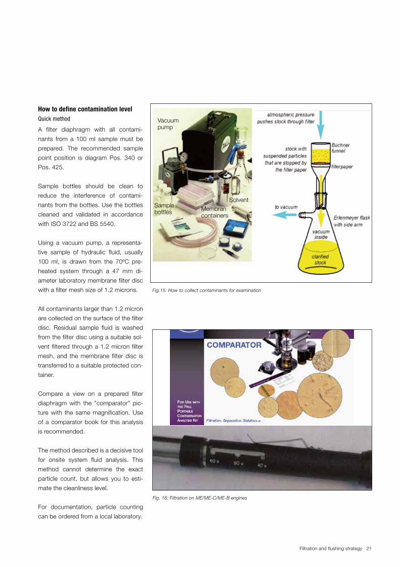
How to define contamination levelQuick method
A filter diaphragm with all contami-
nants from a 100 ml sample must be
prepared. The recommended sample
point position is diagram Pos. 340 or
Pos. 425.
Sample bottles should be clean to
reduce the interference of contami-
nants from the bottles. Use the bottles
cleaned and validated in accordance
with ISO 3722 and BS 5540.
Using a vacuum pump, a representa-
tive sample of hydraulic fluid, usually
100 ml, is drawn from the 70ºC pre-
heated system through a 47 mm di-
ameter laboratory membrane filter disc
with a filter mesh size of 1.2 microns.
All contaminants larger than 1.2 micron
are collected on the surface of the filter
disc. Residual sample fluid is washed
from the filter disc using a suitable sol-
vent filtered through a 1.2 micron filter
mesh, and the membrane filter disc is
transferred to a suitable protected con-
tainer.
Compare a view on a prepared filter
diaphragm with the ”comparator” pic-
ture with the same magnification. Use
of a comparator book for this analysis
is recommended.
The method described is a decisive tool
for onsite system fluid analysis. This
method cannot determine the exact
particle count, but allows you to esti-
mate the cleanliness level.
For documentation, particle counting
can be ordered from a local laboratory.
Fig.15: How to collect contaminants for examination
Vacuumpump
Sample bottles Membran
containers
Solvent
Fig. 16: Filtration on ME/ME-C/ME-B engines
22 Filtration and Flushing strategy
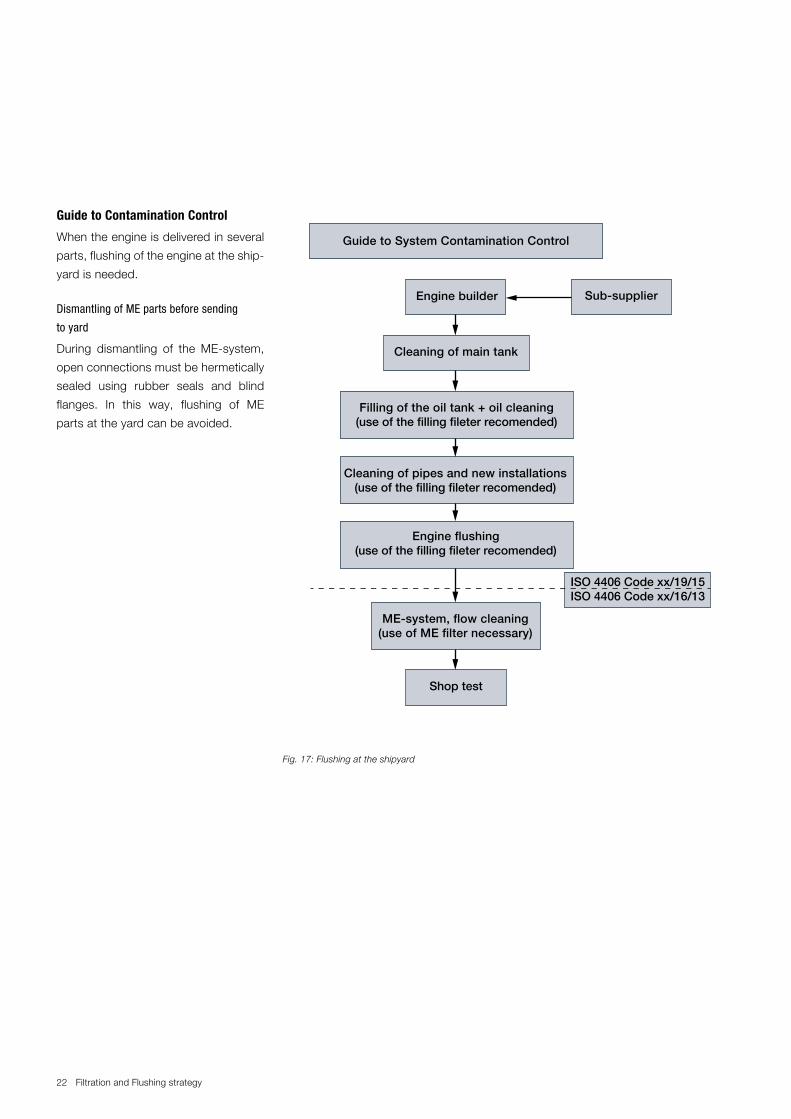
Guide to Contamination Control
When the engine is delivered in several
parts, flushing of the engine at the ship-
yard is needed.
Dismantling of ME parts before sending
to yard
During dismantling of the ME-system,
open connections must be hermetically
sealed using rubber seals and blind
flanges. In this way, flushing of ME
parts at the yard can be avoided.
Fig. 17: Flushing at the shipyard
Guide to System Contamination Control
Engine builder
Cleaning of main tank
Filling of the oil tank + oil cleaning(use of the filling fileter recomended)
ISO 4406 Code xx/19/15ISO 4406 Code xx/16/13
Cleaning of pipes and new installations(use of the filling fileter recomended)
Engine flushing(use of the filling fileter recomended)
ME-system, flow cleaning(use of ME filter necessary)
Sub-supplier
Shop test
23Filtration and flushing strategy
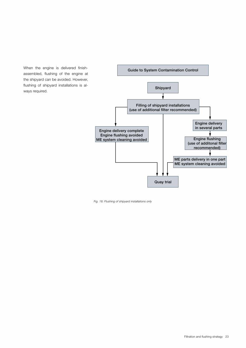
When the engine is delivered finish-
assembled, flushing of the engine at
the shipyard can be avoided. However,
flushing of shipyard installations is al-
ways required.
Fig. 18: Flushing of shipyard installations only
Guide to System Contamination Control
Filling of shipyard installations(use of additional filter recommended)
Shipyard
Quay trial
Engine deliveryin several parts
ME parts delivery in one partME system cleaning avoided
Engine flushing(use of additonal filter
recommended)
Engine delivery completeEngine flushing avoided
ME system cleaning avoided
24 Filtration and Flushing strategy
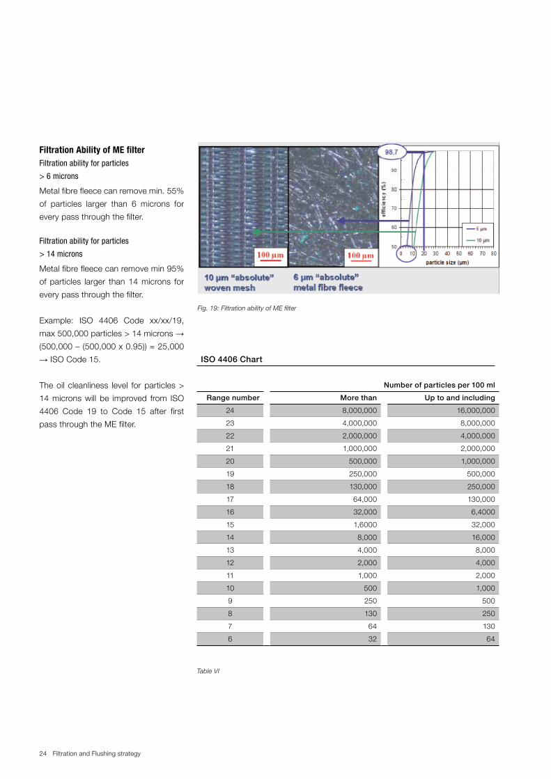
Filtration Ability of ME filterFiltration ability for particles