100
Master of Science Thesis Stockholm, Sweden 2007 COS/CCS 2007-19 PETTER EDSTRÖM Overhead Impacts on Long-Term Evolution Radio Networks KTH Information and Communication Technology
Master of Science ThesisStockholm, Sweden 2007
COS/CCS 2007-19
P E T T E R E D S T R Ö M
Overhead Impacts on Long-TermEvolution Radio Networks
K T H I n f o r m a t i o n a n d
C o m m u n i c a t i o n T e c h n o l o g y
Overhead Impacts on Long-Term Evolution Radio Networks
Petter Edström
Master of Science Thesis in Information Technology
School of Information and Communications Technology (ICT)
Royal Institute of Technology (KTH)
Project conducted at
Wireless Access, Radio Network Features
Ericsson Research
Ericsson AB
May 31, 2007
Supervisor at Ericsson: Supervisor and Examiner at KTH: Arne Simonsson, Gerald Q Maguire Jr. Senior Specialist, Radio Network Product Performance Professor, Radio Network Features, Wireless Access Department of Communication Systems (COS), ICT Ericsson Research, Ericsson AB Royal Institute of Technology (KTH) Luleå, Sweden Kista, Sweden
Overhead Impacts on Long-Term Evolution Radio Networks
2 (98)
Overhead Impacts on Long-Term Evolution Radio Networks
Abstract As a result of the constant efforts to improve mobile system performance and spectral efficiency, the 3GPP standardization forum is currently defining new architectural and functional requirements that hope to ensure long-term evolution (specifically defined as the “Long-Term Evolution (LTE) concept”) and general future competitiveness of the 2G and 3G radio access technologies.
Previous discussions on LTE efficiency have been focused on general assumptions on signaling overhead and overall system capacity, based on experience from existing mobile systems. However, as 3GPP standardization has become more mature (although not yet settled), there is a need to investigate how different potential LTE services will be affected by the use of available overhead information and basic scheduling algorithms.
This thesis investigates the lower protocol layers’ overhead impacts on the downlink for different packet switched services, in an LTE radio access network (RAN).
Results show that the use of RTP/TCP/IP header compression (ROHC) is the single most important factor to reduce payload overhead, for packet sizes of ~1kB or smaller. However, for packets larger than ~1 kB, the use of ROHC becomes insignificant.
Protocol headers – including the AMR frame header, RLC/MAC headers, and CRC where applicable – remain the largest part of payload overhead regardless of packet size and header compression (ROHC).
For VoIP over the UDP protocol (with ROHC), RLC/MAC headers constitute the largest part of protocol headers.
For TCP/IP applications (without ROHC), TCP/IP headers are predominant.
Services that require packet sizes beyond ~1 kB will require about the same power per payload bit regardless of percentage of payload overhead.
Keywords
Long-Term Evolution, LTE, Power Emission, Efficiency

Overhead Impacts on Long-Term Evolution Radio Networks
3 (98)
Sammanfattning Som ett resultat av ständiga ansträngningar att förbättra såväl prestanda som spektrumeffektivitet för mobila system, definierar 3GPPs standardiseringsforum nya krav på arkitektur och funktionalitet. Dessa är avsedda att säkerställa långsiktig utveckling (explicit definierat som konceptet “Long-Term Evolution (LTE)”, samt framtida konkurrenskraft för både 2G och 3G som radioaccess-teknologier.
Tidigare diskussioner rörande effektivitet inom LTE har fokuserat på allmänna antaganden vad gäller kontrolldata för signallering och övergripande systemprestanda. Dessa har i sin tur baserats på erfarenheter från existerande mobilsystem. När standardiseringen inom 3GPP mognar uppstår nu ett behov av att undersöka hur olika tjänster inom LTE påverkas, av såväl hur man använder den kontrollinformation som finns tillgänglig, som av basala algoritmer for schemaläggning av resurser.
Denna rapport undersöker påverkan från lägre protokoll-lagers kontrollinformation på nerlänken hos olika paket-kopplade tjänster inom ett radioaccessnät för LTE.
Resultaten visar att användandet av ROHC (som packar kontrollinformation för protokollen RTP/TCP/IP), är det ensamt viktigaste bidraget till minskad kontrollinformation i relation till informationsbitar för paketstorlekar upp till c:a 1kB. För större paket är vinsten med ROHC dock försumbar.
Kontrollinformation för protokoll – inkluderat data avsett för AMR-tal-ramen, RLC/MAC-protokollen, samt CRC – utgör för övrigt en stor del av kontrollinformationen relativt informationsbitar, oavsett paketstorlek och packning av kontrolldata.
Tjänster som kräver paketstorlekar på över c:a 1 kB kräver uppskattningsvis samma mängd energi per informationsbit, oavsett andelen kontrollinformation.
Overhead Impacts on Long-Term Evolution Radio Networks
4 (98)
Acknowledgements
I extend my deepest gratitude to Anders Furuskär, Magnus Lindström, Stefan Parkvall and Fredrik Persson at Ericsson Research, for much appreciated guidance on the latest news on 3GPP discussions on channel configurations and overhead data constellations, in spite of their tight schedules.
My advisor at Ericsson Research, Arne Simonsson has never ceased to support me with insightful ideas and encouragement for the duration of this thesis.
Discussions with Mårten Ericsson have been very useful when investigating similarities and differences between the LTE and WCDMA/HSDPA access networks.
I would also like to thank Karolina Bergman, Mikael Bertze, Mårten Sundberg and Magnus Thurfjell for helpful Matlab support.
Professor Gerald Q Maguire Jr, has provided me with valuable hints during the planning and writing of this thesis.
Last by not least I would like to thank my manager at Ericsson, Lennart Blixt, for being very understanding and supportive as I have tried to coordinate my studies with my employment duties at Ericsson.
Overhead Impacts on Long-Term Evolution Radio Networks
5 (98)
Table of Contents 1 Introduction ...................................................................................... 6
1.1 Background.......................................................................... 6 1.2 Standardization Efforts for Improved Performance .............. 8 1.3 Problem Statement............................................................... 8 1.4 Method ................................................................................. 9 1.5 Thesis Outline .................................................................... 10
2 Technical Background.................................................................... 12 2.1 Multi-Carrier Modulation and FDM..................................... 12 2.2 Orthogonal Sub-Carriers in OFDM..................................... 14 2.3 The OFDM System Model.................................................. 14 2.4 Coding and Interleaving ..................................................... 14 2.5 Speech Encoding in LTE.................................................... 15 2.6 Discontinuous Transmission .............................................. 16 2.7 The Cyclic Prefix ................................................................ 16 2.8 OFDM Advantages............................................................. 18 2.9 OFDM Impairments............................................................ 19 2.10 LTE Network Architecture................................................... 24 2.11 Radio Interface Protocol Architecture................................. 25 2.12 Protocol Overhead Considerations .................................... 28 2.13 Multiplexing & Multiple Access........................................... 29 2.14 LTE Resource Blocks & Resource Elements ..................... 29 2.15 Channels and Signals ........................................................ 32 2.16 Control Channel Transmit Diversity.................................... 39 2.17 MIMO ................................................................................. 39
3 Previous Studies ............................................................................ 40 3.1 Expectations of LTE ........................................................... 40 3.2 3GPP LTE Standardization ................................................ 46 3.3 Potential Standardization Improvements............................ 48
4 Radio Network Model: Assumptions & Parameters ....................... 50 4.1 Link Performance Model Definition .................................... 50 4.2 Protocol Overhead ............................................................. 51 4.3 Scheduling Overhead......................................................... 52 4.4 Summary of Control Information Overhead ....................... 54 4.5 Definition of Total Overhead............................................... 55 4.6 Overhead Data Impacts on Service Performance.............. 57 4.7 Energy Transmission Considering DTX ............................. 58 4.8 Environment Details ........................................................... 58
5 Results ........................................................................................... 61 5.1 Common Control Information Overhead ............................ 61 5.2 SID-frames, Scheduling, and HARQ ACK/NACK............... 63 5.3 Protocol Overhead ............................................................. 67 5.4 Total Overhead................................................................... 69 5.5 Required Energy for Service Provisioning ......................... 73 5.6 Boosted Reference Signal Power ...................................... 77
6 Discussion ..................................................................................... 79 7 Conclusions ................................................................................... 81 8 Further Studies .............................................................................. 82
Appendix A: Extended Cyclic Prefix Figures………………………. 90 Appendix B: Concepts………………………………………………... 94 Appendix C: Abbreviations…………………………………………… 98
Overhead Impacts on Long-Term Evolution Radio Networks
6 (98)
1 Introduction
1.1 Background
Today there are in excess of 2 billion users of mobile systems for wireless communication [1]. Alongside GSM, the most deployed mobile Radio Access Network (RAN) technology by far, there are other technologies emerging, such as Wideband Code-Division Multiple Access (WCDMA)-High Speed Packet Access (HSPA) and Long-Term Evolution (LTE).
Enhanced modulation techniques such as Orthogonal Frequency Division Multiplex (OFDM) – used with LTE – as well as numerous other services such as wireless local area networks (WLANs), Asymmetric Digital Subscriber Line (ADSL), and Very high-rate Digital Subscriber Line (VDSL), increases the end-users’ expectations on available services, their availability and performance. This contributes to new requirements on efficient use of available spectrum.
New technologies provide higher peak data rates. This requires that the use of power over a limited bandwidth and the subsequent introduction of network interference are carefully considered.
When information is transferred over a radio interface in a wireless mobile system such as LTE, a frequency carrier of a specified bandwidth is modulated with information and coded at the transmitting end, conveying information that can be interpreted by the receiver despite interference and signal degradation along the transmission path. Designers of packet switched wireless systems try to use the available frequency spectrum as efficiently as possible with regards to both payload and control information given the busty nature of packet-oriented end-user transmissions. High spectrum efficiency can provide service to more users, or higher data-rate end-user services to fewer users over a fixed allocation of spectrum. Improving service performance for some or increasing service availability for many users while using the same amount of bandwidth, are both examples of the improved spectral efficiency sought for packet switched services.
In contemporary packet switched mobile systems a number of information bits are coded into symbols that are modulated onto one single carrier as a single stream of data. When transmission rates are increased in the ongoing quest for improved spectral efficiency (or more specifically higher end-user data rates while still using the same limited bandwidth), the time used to transmit each symbol over a single carrier is decreased. A shorter symbol time renders the system more susceptible to losses along the transmission path, noise (impulse noise in particular), and interference on symbol or carrier level. The alternative however – using a wider bandwidth to combat losses and interference (normally required for achieving higher data rates over a single carrier) – increases the risk of being subject to single strong interference sources that use the same or adjacent resources in time and frequency.
Overhead Impacts on Long-Term Evolution Radio Networks
7 (98)
Using available techniques and an OFDM carrier constellation, an efficient implementation that enables multiple, relatively robust (considering interference), and narrowband carriers can be quite easily deployed in theory with the use of Fourier transformations. However, in practical systems, system impairments and inaccuracies caused by transceiver equipment and radio propagation properties will reduce the stability and robustness of a system with multiple carriers and a limited bandwidth. These imperfections need to be accommodated in order to minimize unwanted interference and the subsequent reduction in spectral efficiency.
Alongside the need for an efficient technique enabling increased spectrum efficiency there are several access technologies attempting to co-exist in the wireless market. An increasingly important factor in the planning of such multi-access technology networks is the use of energy. Two main reasons stand out when discussing why the use of energy is so important in complex mobile networks;
1. Cost savings. Network operators’ costs for running mobile networks are increasing. The power inefficiency – considering that transmitted power has been subject to feeder losses, and that power is required for cooling – heavily affects an operator’s expenditure. This is more and more of a concern since adequate service performance needs to be provided at all times, irrespective of the energy levels that need to be transmitted. Different levels of network load provide an opportunity to reduce energy consumption, if transmitted energy can be lowered to match the need for the load in the network (given that the service level can be maintained). As a consequence, lower end-user tariffs and maintaining return-on-investment targets in modern mobile networks suggest that operators should minimize their energy consumption while providing a given service with acceptable coverage and capacity.
2. High power levels cause network interference. Emission of power from a mobile network base station causes interference in the surrounding area. This impacts service accessibility, retainability and overall performance. In order to optimize performance it is of utmost importance to reduce the intra-system and inter-system interference when services are provided in co-existing networks with limited spectrum. The information transmitted to and from a system should ideally only use only as much energy as necessary to provide this service, in order to maximize performance on a network level.
In order to save energy and minimize interference in the long run on the network level, the service performance impacts of transmitted energy (in terms of interference as well as payload and overhead data) need to be considered. For deployment in different environments, constellations, or user scenarios, the relative effectiveness of the transmitted energy needs to be explicitly understood - specifically addressing control information when using different types of services. Impacts from OFDM system impairments should ideally be accounted for whenever applicable.
Overhead Impacts on Long-Term Evolution Radio Networks
8 (98)
Another aspect of optimizing service and system performance is the coordination of the scheduling of available radio resources. The scheduling procedures need to be adapted for best possible service performance from an end-user perspective, given a certain interference situation. Current standardization activities [28] are addressing many aspects of scheduling coordination. For this reason, optimized and coordinated scheduling is left for others to investigate in detail.
1.2 Standardization Efforts for Improved Performance
As a result of the constant effort to improve mobile system performance and spectral efficiency, the 3GPP standardization forum is currently defining new architectural and functional requirements that ensure long-term evolution (specifically defined as the LTE concept) and general future competitiveness of the 2G and 3G radio access technologies. The evolution from the existing GSM and basic WCDMA access technologies is addressed [50], as well as further enhancements through HSPA [51] and the LTE concept. The main foci are increased spectrum efficiency, data rates, and coverage, as well as reduced latency. Considering the downlink, the focus of this thesis, spectrum efficiency as well as the mean and cell-edge user throughputs are proposed to be increased to three times that of a basic WCDMA system (as defined in the 3GPP standards release 99). In addition to these foci, flexible spectrum allocations, reduced costs, peak data rates above 100 Mbps, and a significantly reduced latency for control information, are included as targets for performance improvements. More comprehensive information on the evolution of the LTE standard is available in [28] and [32].
1.3 Problem Statement
Changing the level of emitted power is the major factor which can alter levels of interference in a network. This is one of the major aspects of potentially improved resource utilization in addition to reduced operator expenditure for electrical power. However, there is no linear relation between the reduction of power and lower interference in a network. Nor is there a linear relationship between the reduction of transmitted power and the electrical power consumed. Therefore it is important to investigate how efficiently a modern mobile system such as LTE can use the available power to provide adequate services.
Since the resource structure in an OFDM based LTE system enables optimum use of resources whenever orthogonality can be maintained, it would be interesting to investigate the energy required to transfer various amounts of payload data, given that different services likely have different overhead information.
A few introductory concerns describe the basic issues that will be dealt with in this thesis:
• How much energy is required for different packet sizes in an LTE network?
• How much and what type of overhead data exists and what are the basic overhead requirements for different types of services, numbers of users, and potential downlink antenna configurations?

Overhead Impacts on Long-Term Evolution Radio Networks
9 (98)
1.4 Method
The aim of this investigation is to describe the relative efficiency with which available radio resources are deployed in LTE, using different end-user services, in order to obtain generally higher data rates and lower latency than what is achievable with conventional mobile systems, being they 2G or 3G, deploying EDGE or HS(D)PA.
When investigating the performance impacts from the use of extensive control information, the extreme cases of two very different services would be interesting to compare; one service being sensitive to delays using very small packets, and another service using large packets that can sustain larger service and end-to-end delays. Examples of such services could be VoIP and an FTP transfer over TCP (respectively). Previous investigations of LTE system capacity have focused on absolute levels of capacity and on one service only, mainly speech services over VoIP using AMR CODECs. Theoretical capacity estimates at the system level have also assumed the use of a predefined, constant level of overhead and the use of only one speech CODEC, without considering the actual energy consumption per unit of transferred information content in an LTE system.
Upcoming investigations will first of all try to clarify the energy needed for a basic service, given different AMR CODECs, including DTX activation. All types of overhead required to enable downlink connection establishments will be investigated in detail. Overhead related to the actual payload transfer will be examined separately, including the impact of using different types of resource scheduling algorithms.
The results from this study will hopefully clarify previous issues of concern for overhead and resource efficiency in LTE, especially for services with high demands for low service delays. In addition, recent progress in the 3GPP standardization of LTE (with regards to channel constellations and resource mapping), hopefully will enable this thesis to contribute to a more comprehensive understanding of the basic resource requirements related to overhead information, possibly even without regard to the packet sizes used in an LTE downlink transfer.
The necessary steps to achieve these goals include the following actions:
• A literary study of available OFDM techniques and available channel constellations when applied in a mobile system. Suggested frequency planning strategies in LTE, potential OFDM impairments and some reasoning behind packet switched resource management strategies are included for orientation.
• A transmitter energy calculation shall be done including all known channels and signaling, but excluding transmitter losses and other hardware energy consumption. Downlink (base station) energy usage is estimated.
• The considered channel constellations are modeled using a generally accepted link performance model, based on Shannon’s theories adopted to accommodate changes in radio characteristics over the radio interface.

Overhead Impacts on Long-Term Evolution Radio Networks
10 (98)
• Typical end-user services (with different packet sizes) are investigated with regards to the required power levels and chosen scheduling techniques as well as performance, in terms of Ws/Mbits and its inverse Mbits/Ws.
• The signaling overhead needed for the above investigated scenarios, is investigated specifically, both the overhead required on the system level and the additional payload overhead per user (see section 4.4).
There are a number of performance figures that potentially can provide answers, or at least be subject to further investigations based on the problem statement in section 1.3 and initial LTE standardization activities referenced in section 3.1. They can be summarized as:
• What are the Ws/Mbit figures at different packet sizes, with constant system latency?
• How much and what type of overhead data is used, and what are the basic overhead data requirements for different types of services, given the Ws/Mbit figures above, and potential downlink antenna configurations?
The energy cost for a packet-switched transmission in LTE can – given that the propagation losses are accommodated – be approximated as the power used during a specified time interval. Hence, the quantity watt seconds [Ws] will be the relevant unit. Looking at various packet data sizes including necessary overhead data this quantum can be normalized into watt seconds per megabit [Ws/Mb], where the relative energy would be its inverses [Mb/Ws] or [Mbps/W].
This thesis focuses on the downlink of 3GPP LTE, since most services require higher throughput and increased efficiency specifically for downlink transmissions. Secondly, many of the channel content details related to the uplink have yet to be standardized.
Potential system impacts on system characteristics from OFDM impairments are discussed mainly for orientation. Predominant performance bottlenecks due to impairments have been identified on the uplink during this thesis; hence impairments will not be handled specifically, as the focus is on downlink performance.
Current standard assumptions and state of the art algorithms and solutions are assumed.
Unless stated otherwise, references to the status of 3GPP standards are up-to-date as of December 2006.
1.5 Thesis Outline
An historical background to the evolution of the OFDM technique, the basic properties of OFDM, the access technology deployed in LTE, and the intended LTE network architecture and channel constellations are all investigated in section 2. Concerns for LTE system performance are also handled in this section (for orientation).

Overhead Impacts on Long-Term Evolution Radio Networks
11 (98)
Previous studies on energy emission and 3GPP LTE related radio resource management techniques are examined in section 3.
The applied evaluation model, assumptions and parameters are described in section 4.
Results are presented in section 5.
Section 0 discusses interpretations of these results.
Finally, sections 7 and 8 contain thesis conclusions and ideas for potential further studies.
Discussions within this thesis, as well as some of the presented results and conclusions conceptually consider different aspects of energy consumption in an LTE network, in the context of:
• Recently discussed 3GPP standardization content for LTE, focusing on the use of overhead data, and
• Potential improvements to reduce the energy consumption in general or for specific services in particular.
It should be noted that the general introduction and the initial sections are intentionally very basic with regards to energy and the use of spectrum. The latter part of this thesis examines protocol details focusing on overhead of the data link layer (layer 2) of the OSI-model, which requires a basic understanding of the protocol structures of data communication.

Overhead Impacts on Long-Term Evolution Radio Networks
12 (98)
2 Technical Background
2.1 Multi-Carrier Modulation and FDM
One modulation technique that has proven very useful given the requirements for high interference and noise robustness, stable channel characteristics and high data rates in current mobile system standardization efforts, is a multi-carrier modulation scheme called OFDM [20]. However, before the advantages and potential impairments of OFDM in mobile systems are discussed, one needs to understand the basic concept of how the available bandwidth is utilized and the techniques that OFDM has evolved from.
Multi-carrier modulation systems, of which OFDM is one example, were first developed during the 1960’s for military applications. Keller and Hanzo [26] and references therein provide further details on the historical details of these pioneering applications of multi-carrier modulation. When the Discrete Fourier Transform was proposed for modulation and demodulation some years later in 1971 [25], mathematical operations - using Fourier transforms - could be applied to transform data between the time and frequency domains. One example of an early implementation of OFDM with parallel carriers is the Telebit Trialblazer Modem, using the packet ensemble protocol [53].
The fast Fourier transform (FFT) and related frequency domain calculations made it possible to introduce OFDM carriers using a digital modem, since data could be mapped onto orthogonal carriers.
Advances in hardware design have made it possible to use FFT (and its inverse IFFT) handling OFDM channels on integrated circuits for commercial applications, albeit not yet in commercial wide area mobile systems [21]. IEEE 802.11a/g and Hiperlan2 (WLAN/WiFi), Digital Audio Broadcasting (DAB), and terrestrial Digital Video Broadcasting (DVB-T) are but a few examples of current wireless OFDM applications. OFDM is also used for wired applications such as ADSL – where it is often referred to as Discrete Multitone Modulation.
The available spectrum intended for high data rates in a multi-carrier modulation system is divided into a large number of sub-channels of slower rates. Parallel carriers can then be assigned simultaneously using frequency division multiplexing technique (FDM). Having a number of parallel narrow-band channels instead of one wideband channels drastically simplifies the equalization process that operates upon a signal at the receiver. A channel that is small enough to be considered narrow-band can also be considered to have constant or flat fading frequency characteristics [23], [24]. Such a channel can be interpreted by a much simpler equalizer than one designed for processing wideband channels.
Overhead Impacts on Long-Term Evolution Radio Networks
13 (98)
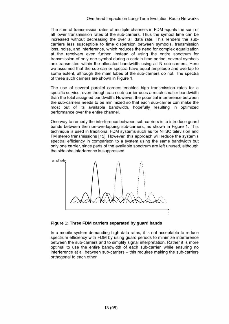
The sum of transmission rates of multiple channels in FDM equals the sum of all lower transmission rates of the sub-carriers. Thus the symbol time can be increased without decreasing the over all data rate. This renders the sub-carriers less susceptible to time dispersion between symbols, transmission loss, noise, and interference, which reduces the need for complex equalization at the receivers even further. Instead of using the entire spectrum for transmission of only one symbol during a certain time period, several symbols are transmitted within the allocated bandwidth using all N sub-carriers. Here we assumed that the sub-carrier spectra have equal amplitude and overlap to some extent, although the main lobes of the sub-carriers do not. The spectra of three such carriers are shown in Figure 1.
The use of several parallel carriers enables high transmission rates for a specific service, even though each sub-carrier uses a much smaller bandwidth than the total assigned bandwidth. However, the potential interference between the sub-carriers needs to be minimized so that each sub-carrier can make the most out of its available bandwidth, hopefully resulting in optimized performance over the entire channel.
One way to remedy the interference between sub-carriers is to introduce guard bands between the non-overlapping sub-carriers, as shown in Figure 1. This technique is used in traditional FDM systems such as for NTSC television and FM stereo transmissions [15]. However, this approach will reduce the system’s spectral efficiency in comparison to a system using the same bandwidth but only one carrier, since parts of the available spectrum are left unused, although the sidelobe interference is suppressed.
f
amplitude
Figure 1: Three FDM carriers separated by guard bands
In a mobile system demanding high data rates, it is not acceptable to reduce spectrum efficiency with FDM by using guard periods to minimize interference between the sub-carriers and to simplify signal interpretation. Rather it is more optimal to use the entire bandwidth of each sub-carrier, while ensuring no interference at all between sub-carriers – this requires making the sub-carriers orthogonal to each other.

Overhead Impacts on Long-Term Evolution Radio Networks
14 (98)
2.2 Orthogonal Sub-Carriers in OFDM
The O in OFDM represents the ideal suppression of interference between the narrowband sub-carriers in an FDM system. When sub-carriers are made orthogonal to each other, the interference between them is eliminated. The energy from any orthogonal sub-carrier is completely uncorrelated with that of the other sub-carriers, and cannot be interpreted as useful energy by another sub-carrier. This allows the spectra of the sub-carriers to overlap, transmitting more information over the same total bandwidth without causing interference. This also improves the spectral efficiency of the system. With overlapping sub-carriers that are perfectly orthogonal, the equalization in the receiver is made easy, and the number of sub-carrier that can be used over a specified spectrum is doubled as compared to FDM using guard periods [4].
The technique used to generate orthogonal frequencies in OFDM is based upon using the Inverse fast Fourier transform (IFFT) operations. Details of this will be discussed in later sections. A basic system layout when deploying OFDM is shown in Figure 2.
2.3 The OFDM System Model
A simple model of a communication system consists of a source and related coding, a well defined channel, some signal processing, and a receiver at the end of the transmission path. The receiver decodes the received signals and processes the input to extract the desired signal from transmission impairments and interference. Figure 2 displays such a simplified model. It should be noted that the necessary conversions between serial and parallel data streams are implicitly implemented and not shown in the figure.
h1[n]
h2[n]
hN[n]
Channel encoderInput data bit stream
Modulation
Mapping
Transformation of symbolsFrequency Domain ->
Time Domainusing IFFT
Data mapped onto N orthogonal subcarriers
Parallel signals convertedInto serial stream
CyclicPrefix
Digital/Analog conversion
Low pass filtering
FrequencyCarrier Modulation
Figure 2: A simplified model of a downlink OFDM transmission
2.4 Coding and Interleaving
In [15], Coded OFDM is referred to as a concept of closely connecting error control coding and modulation in OFDM. Coding and interleaving prior to the IFFT transformation from data in a continuous frequency domain into the discrete time domain, is vital for deployment of OFDM in a mobile system.

Overhead Impacts on Long-Term Evolution Radio Networks
15 (98)
Interleaving spreads out bit errors so that the receiver more easily can interpret the transmitted data and the now loosely spaced errors. This technique is especially important in a mobile communication system with varying radio characteristics when using packet switched services. The data is transmitted upon request (and potentially over several transmission paths) which creates bursts of information bits. If an entire burst in such a transmission were lost, the receiver would have a very difficult task to re-create the transmitted data. The interleaving (which performs a spreading in time) allows different error correction bits to be applied to the different errors which occurred during a narrow interval of time to the interleaved signal; if the error affects less than the number of bits which can be corrected, then the entire message can be received - despite the errors.
As coding and interleaving are such fundamental components of the information processing over fading channels in a mobile network, these ideas are not considered specifically but included implicitly on link level when discussing packet transfers in a mobile system such as LTE (as depicted in Figure 3).
Source Encoding
Speech Processing
Channel Encoding
Multiplexing Differential Encoding(to enable interpretation of a
modulated signal)
Encryption Modulation
Block encoding (CRC) FEC (Turbo Coding) InterleavingBlock encoding (CRC) FEC (Turbo Coding) Interleaving
Figure 3: Basic elements of a transmission chain on the physical layer
2.5 Speech Encoding in LTE
The first step in digital speech transmission is coding of the speech itself, shown as source coding in Figure 3. Most of the available Adaptive Multi Rate (AMR) speech CODECs used in both GSM and WCDMA/HSPA systems have been assumed for speech services in LTE as well, providing several different CODEC rates depending on the coding needed in different radio environments [43]. The basic CODECs assumed for LTE are AMR 4.75, 5.9, 7.4, 12.2 for narrowband AMR, and AMR 6.60, 8.85, and 12.65 for wideband AMR deployment [63].
Each of these speech CODECs classifies the speech into bits of different grades of significance, class A through C (only class A and B are used for Wideband AMR). Each class of bits is separately coded since class A specifies the most important bits and class C the least important bits. Erroneous class A bits typically result in a corrupted speech frame, which is why all class A bits are always subject to a cyclic redundancy check (CRC) to detect bit errors. The CRC is added as an extra bit in the AMR speech frame1. Erroneous class B bits typically do not cause serious degradation in the perception of the speech frame, and class C bits consequently are of even lower importance.
1 A speech frame is sent every 20 ms, corresponding to the time segmentation of speech transcoders
Overhead Impacts on Long-Term Evolution Radio Networks
16 (98)
The AMR speech frame structures are described in [43]. In addition to the speech payload each speech frame consists of a header and auxiliary information (for mode adaptation and error detection).
The coding of the channel carrying speech frames depends on the chosen modulation schemes for that channel, i.e. the PDSCH (described in an upcoming section). Although several modulation schemes are possible, 16 QAM has been chosen as a likely general modulation for data channels in LTE systems.
2.6 Discontinuous Transmission
To conserve energy and optimize use of bandwidth, silent periods in a conversation can be detected both on the uplink and downlink and indicated using silence indicator (SID) frames. DTX transmission can then adjust for the active speech intervals and transmit less information as well as avoid coding and decoding of empty speech frames. AMR packets use SID frames containing 39 payload bits2 [49], including information on comfort noise3. During DTX, these SID frames are sent once every eighth speech frame (every 160 ms). The speech frame overhead discussed in section 4.2 is added onto both SID frames and regular speech frames, albeit the minimum header compression size is larger for SID frames. Hence; SID frames are not considered overhead information in an LTE system, but payload sent during periods of no speech.
Compared to the active AMR 12.2 speech frame payload of 244 bits [49] sent every 20 ms during speech periods, the mean bit rate would be reduced by 98
% during DTX periods, since the SID frame bitrate is 75.243
16039
= [bits/ms]
which equals 244 bits/s or 2 % of the bitrate for a AMR packet coded for 12.2 kbps.
2.7 The Cyclic Prefix
As previously mentioned, Inter-Carrier Interference (ICI) is eliminated if the sub-carriers can be kept perfectly orthogonal to each other. However, in a mobile system with constantly changing radio conditions, this orthogonality can not be maintained. This results in both inter-carrier and inter-symbol interference (ISI). The latter is produced when a mobile system is subject to multipath fading where signals travel over different paths.
2 Excluding associated overhead [43]. 3 Noise characteristics are sent to provide the illusion of a constant voice data stream. Comfort noise prevents the user from disconnecting based on the assumption that the connection is lost when the speaker is silent.

Overhead Impacts on Long-Term Evolution Radio Networks
17 (98)
By copying a number of samples at the end of a symbol and adding these to the beginning of the same symbol, both ICI and ISI can be avoided (see Figure 4) once the added cyclic prefix is filtered out by the receiver. However, as shown in the lower part of Figure 5, it is vital that the length of the cyclic prefix is appropriate with regards to the maximum delay spread or multipath delay of the channel. For instance, if the multipath delay of the channel is longer than the cyclic prefix the orthogonality is lost at the receiver despite these counter measures, and both ICI and ISI are introduced when trying to interpret the signal. Note that the channel’s characteristics are left out of Figure 5, to simplify the example.
Total symbol length after inserting the cyclic prefix, Ttotal
Cyclic prefix, Tcp Symbol length without the cyclic prefix, Ts
Figure 4: Adding a cyclic prefix to an OFDM symbol
Adding extra bits to an OFDM symbol consumes additional power and will affect the user-data bitrate since more time is spent on sending the same amount of user-data but with more control information overhead. Looking at this at one instant in time, one realizes that when using a longer symbol time, a smaller percentage of bits is added to the symbol in the form of the cyclic prefix.
Considering spectrum efficiency, one would like the symbol time to be as long as possible, given that the data throughput can remain unchanged. However, unless the channel fading can be considered constant during one sub-carrier, a simplified receiver design can no longer be used, since the sub-carriers no longer can be considered narrow-band and flat-fading. Hence the symbol time needs to be shorter (preferably much shorter) then the coherence time – during which the channel can be considered constant – in order to still benefit from using the cyclic prefix [4].
Transmitted signal
Received Signal using correct CP length
t
CP CP CP CP
Signal reconstructedwithout ICI or ISI
Signal reconstructedwithout ICI or ISI
t
ICI and ISI added to the signal
ICI and ISI added to the signalReceived
signal using a too
short CP

Overhead Impacts on Long-Term Evolution Radio Networks
18 (98)
Figure 5: Effects of using a cyclic prefix of different lengths
The effectiveness of the cyclic prefix given that extra overhead and power is needed, has been questioned in several studies, for instance in [6] and [7]. Herein it is investigated how to increase system performance and potentially also spectral efficiency without adding as much control overhead as is needed for the cyclic prefix and the necessary channel estimation information. The channel estimation information is used to estimate the channel’s impact on the signal, in order to apply appropriate countermeasures at the receiver. Although considerable amounts of control data is used when adding a cyclic prefix, the complexity of using the type of OFDM modification suggested in [6] in a mobile system, and existing OFDM simulation tools [4], still suggest the use of a cyclic prefix. Hence, it will be used in this thesis unless specifically stated otherwise. The use of a cyclic prefix is also recommended in the 3GPP standardization for LTE, where two fixed prefix lengths are defined. These are intended to compensate for different maximum delay spreads for different cell or transmission properties [31].
Further details discussing the usability of the cyclic prefix are presented in section 3.3.1.
2.8 OFDM Advantages
The OFDM technique offers a number of potential performance advantages against a system using a single frequency carrier. This section presents a summary of the main aspects of OFDM that make it desirable in a mobile communication system [4], [12].
• Robustness against Multipath Fading: OFDM makes use of several parallel sub-carriers to transmit information. More time can then be spent on transmitting each symbol, compared to when symbols are transmitted over a single limited frequency carrier. With a long symbol time, potential multipath delay would impact a smaller fraction of the symbol time, making it easier for the equalizer in the receiver to compensate for the multipath differences. As a consequence the receiver design can be simplified.
• Higher Spectral Efficiency: If parallel sub-carriers can be kept orthogonal to each other, then several spectra can overlap. This enables transmission of more data over a fixed bandwidth without causing performance degrading interference.
• Robustness against Frequency-selective Fading: The available spectrum is divided into several narrow-band sub-carriers. Potential frequency selective fading will affect each sub-carrier’s performance respectively. However, since the bandwidth of each sub-carrier is small, the performance loss of these sub-carriers can be accommodated with efficient coding.
• Modulation & Code Rates: One user can utilize several sub-carriers. As each sub-carrier can use different modulation techniques and code rates, the end-user performance can be optimized in comparison to when using only one modulation technique and one or a few code rates.

Overhead Impacts on Long-Term Evolution Radio Networks
19 (98)
• Spectrum scalability: If several of the narrow-band sub-carriers are unused, they can be allocated to other services. However, due to interference from sidelobes of neighbouring sub-carriers, effective filtering needs to be applied and the excluded sub-carriers need to be contiguous and of significant numbers to prevent interference between sub-carriers. Due to complexity, practical implementations of this remains to be evaluated [4].
• Simplification for MIMO: Systems planned to use flat fading channels can utilize OFDM properties, since narrow-band flat fading channels are deployed.
2.9 OFDM Impairments
Although the OFDM technique presents numerous advantages and has high potential for supporting demanding packet data services – as summarized in section 2.8 – the implementation of OFDM in a practical system such as LTE reveals stability concerns that need to be handled (optimally) to achieve the performance goals of LTE.
Before discussing the details of such radio channels one must be familiar with the basics properties of a radio channel subject to different types of fading. The type of fading mostly depends on factors such as multi-path propagation, time dispersion, and time variance (Doppler frequency shift), all affecting the radio channel.
Significant OFDM impairments include
• Frequency offsets,
• time offsets,
• phase offsets and
• sampling rate changes, that all impact the orthogonality,
as well as
• a high peak-to-average ratio that reduces the power efficiency,
and
• performance degradation from added overhead during transmission.

Overhead Impacts on Long-Term Evolution Radio Networks
20 (98)
When a radio channel varies over time, and its characteristics are fluctuating during one OFDM symbol period, the desired orthogonality is lost. This reduces a sub-carrier’s useful signal and introduces inter-carrier interference (ICI) and inter-symbol interference (ISI) (as described in section 2.7). With a reduced signal and increased interference, the effective signal-to-interference-and-noise ratio (SINR) is reduced. Lower SINR implies a low tolerance for interference and noise, which likely results in lower bitrates and worse overall performance. In addition to this, symbols sent on channels with high attenuation are more difficult to reconstruct at the receiver. For these reasons it is imperative that the synchronization between the transmitter and the receiver can be maintained in time as well as in frequency to subsequently suppress interference by restoring orthogonality at the receiver.
However, introduction of ICI and subsequent reduction of SINR are but a few of the impairments that can reduce a mobile communication system’s performance. Many of the OFDM implementation considerations for transmitting and receiving a modulated signal with several parallel sub-carriers and potential system impairments are studied specifically in [15], and some of them will be examined in more detail in later sections, based on previous studies. The intention is to shed some light on how to quantify power usage and signaling overhead, so that service performance and spectrum efficiency can be maximized without using more energy than necessary.
2.9.1 Frequency Errors
In a common radio transmitter a local oscillator and mixer is used to impose lower frequencies onto a high frequency carrier. The receiver then reverses the same technique to extract lower frequency content from the received high frequency carrier. If these local oscillators do not use the exact same frequencies, the result will be an offset in frequency.
The created frequency shift (on all sub-carriers) renders the received sub-carrier frequencies no longer orthogonal, causing energy from one sub-carrier to interfere with that on other sub-carriers. In Fourier transformation theory, this phenomenon is referred to as DFT leakage [15]. If only one carrier would transmit energy and cause interference due to the local oscillator frequency offset, the sub-carrier closest in frequency to the transmitting sub-carrier would intuitively experience the most interference. However, in most OFDM systems, the majority of sub-carriers are used to transmit at the same time. Assuming that the sub-carriers transmit energy - or in this context interference – in a random fashion, the central limit theorem provides us the conclusion that the large number of sub-carriers causing interference to the desired signal can be considered to be additive white Gaussian noise. In order to combat the introduced loss of orthogonality, a correction signal could be used to compensate for the offset in the original signal. However, if the correction factor is not of the exact same size as the original frequency offset, the problem of lost orthogonality and introduced interference would still remain. [15]

Overhead Impacts on Long-Term Evolution Radio Networks
21 (98)
Another frequency property concern for the equalizer is the signal level at the receiver. Upon receiving information, the equalizer needs to differentiate between frequency components that are of importance and those that do not contain important information. A low signal needs to be compensated for, but by doing so, there is a risk that a frequency component that has been lost in transmission is interpreted as being of extremely low signal strength. A reliability factor is then used to enable the decoding processes to determine whether an apparently strong received signal should be interpreted or filtered out of the information context. [15]
The reference signal discussed in section 2.15.6 is used in the LTE system to accommodate for such channel changes along the transmission path between the transmitter and receiver.
The impact from frequency error impairments is under investigation in the 3GPP committees. Based on the length of the cyclic prefix, a correctly defined timing assessment of the radio channel is crucial, in order to maintain orthogonality. If the signal, due to frequency errors, is considered outside the timing boundaries of the system, it will not be heard at all, and its energy will be interpreted as interference by receivers.
Timing is critical in an LTE system, in much the same way as power control is a limiting factor in an WCDMA system. At a certain power level in a code division based multiple access system, the introduced interference will make it impossible to decode scrambling codes and differentiate one user from the other. If the timing adjustments in LTE are inadequate, signals will remain undetected and their energy will be interpreted as interference.
However, as the carrier frequency spacing currently is defined as 15 kHz, interference between sub-carriers has been considered manageable. Secondly, the timing issue is mostly an issue for the uplink due to lower sensitivity at the mobile transmitters and receivers. There are several additional concerns with regards to timing, mostly for the uplink, such as random access signaling upon connection establishment. However, these aspects are not considered in this thesis, but will be handled in upcoming supplementary simulation studies in the 3GPP standardization activities, later this year.
2.9.2 Sampling Time offset
Sampling, the process of converting a continuous analogue carrier into time-discrete values, is used to capture digital information at discrete levels transmitted over the frequency band of the carrier.
Overhead Impacts on Long-Term Evolution Radio Networks
22 (98)
The carrier signal is sampled and subsequently quantified into digital values at an ideally static sampling interval. A short sampling interval or a high sampling rate generates many discrete values, which increases the likelihood of a correct reconstruction of the analogue signal. The Nyquist-Shannon sampling theorem – proven in 1949 by Shannon [34] based on Harry Nyquist’s conclusions from 1928 [32] – is also known by many other names due to many complementary discoveries, but is commonly referred to simply as the sampling theorem. This theorem states that in order to reproduce an infinite periodic analogue signal exactly using discrete values, the signal has to have a limited bandwidth and the sampling rate must be at least twice that of the bandwidth of the signal. Problems with having a too short or to long sampling interval are examined further in section 2.9.4.
If the transmitter and receiver would be slightly out-of-synch, a sampling time offset would emerge. The sampling of received signal would then take place at a different time than expected, although at a constant rate. This would mean that the samples taken at the receiver could not be perfectly matched to an OFDM symbol.
The use of a cyclic prefix, described in section 2.7, makes it easier to distinguish between OFDM symbol boundaries. As long as the OFDM symbol boundaries are maintained, a sampling time offset is equivalent to a linear phase shift, which in most cases can be handled by the receiver (see section 2.9.3). However, as even a sampling time offset of just one sample will cause distortion, an optimal design of the cyclic prefix length is crucial in order to avoid both inter-symbol and inter-carrier interference.
2.9.3 Phase Offset
In addition to errors in frequency, the changes in phase of a signal also cause offsets and loss of orthogonality at the receiver. Small phase shifts could normally be corrected by an equalizer, but larger errors could cause errors in bit value interpretation, since the rotation could exceed the area used to decide symbol values. [15] This causes ambiguous bit interpretations. Phase changes are mainly introduced due to multipath fading over the radio interface.
2.9.4 Sampling Rate Error
A sampling rate error or an offset in the sampling frequency occurs when sampling takes place more seldom or more often than expected. In an OFDM system with many parallel sub-carriers, a sampling frequency offset on one sub-carrier causes inter-(sub)- carrier interference in the time domain, since one sampling interval overlaps that of another sub-carrier.
Sampling for instance at too long intervals would in practice cause the channel to be subject to time dispersion, and introduce a risk of aliasing or spectrum distortion, as predicted by Nyquist in [32].
Regardless of the type of sampling frequency offset, energy from one sub-carrier is interfering with other sub-carriers just as with frequency errors described in section 2.9.1.
Overhead Impacts on Long-Term Evolution Radio Networks
23 (98)
2.9.5 A High Peak-to-Average Ratio
A processed OFDM signal (using Fourier analysis) can be approximated with a large number of random components [12], resulting in a Guassian distribution given the central-limit theorem. Components in a Guassian distribution can individually have large peaks resulting in a large dynamic range and a high peak-to-average ratio. This puts high performance requirements on the system amplifiers as well as signal converters in the receiver [4], [12]. If the received signal level is so high that receiver amplifiers or the digital-to-analogue converter are saturated, the signal will be distorted. This distortion introduces non-linearity into the OFDM symbol properties, which in turn causes the bit error probability to increase, and introduces interference outside the intended dynamic range of the receiver, due to added higher frequency harmonics [6], [12].
To reduce implementation costs and system complexity it is therefore of utmost importance to reduce the Peak-to-Average Ratio (PAR) when using advanced modulation techniques to enable higher data rates and greater spectrum efficiency.
To combat a high PAR on the downlink, sub-carriers that do not need to send information can be left empty. Thus, no unnecessary energy is added to the transmitted signal.
2.9.6 Reference Signals
The use of a cyclic prefix to combat ICI and ISI requires that additional bits representing channel state information and the prefix itself are transmitted as shown in Figure 4 on page 17. In addition to the cyclic prefix, channel estimation information is also needed in order to estimate arrival times of received symbols. For this purpose, so called pilot symbols (referred to as reference signals later on in this thesis) are added using a pattern known both to the transmitter and the receiver, thereby allowing the receiver to estimate the channel impacts on both phase and frequency on the transmitted symbols. However, as the pilot symbol positions cannot be used for payload information there is increased overhead. As a consequence, the placing of these pilot symbols becomes crucial for the throughput performance of the system.
Further details on necessary control information and its impacts on service performance are discussed in section 2.15.6.
For FDM systems that cannot rely on time-shifts between users over one channel (as is done in TDM systems), a feedback-loop is needed in order to send channel information and parameter adjustment data to and from the transmitter and receiver [21]. However, if the inherent delay in the system is so long that a parameter change is made based on no longer valid channel data (the fading characteristics have changed and the channel is longer flat fading), this will result in sub-optimal parameter adjustments. This reasoning makes an optimal use of channel information overhead data even more crucial for efficient system utilization.
Overhead Impacts on Long-Term Evolution Radio Networks
24 (98)
2.10 LTE Network Architecture
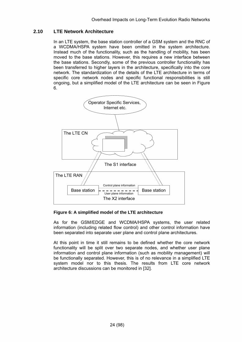
In an LTE system, the base station controller of a GSM system and the RNC of a WCDMA/HSPA system have been omitted in the system architecture. Instead much of the functionality, such as the handling of mobility, has been moved to the base stations. However, this requires a new interface between the base stations. Secondly, some of the previous controller functionality has been transferred to higher layers in the architecture, specifically into the core network. The standardization of the details of the LTE architecture in terms of specific core network nodes and specific functional responsibilities is still ongoing, but a simplified model of the LTE architecture can be seen in Figure 6.
Base station Base station
The X2 interface
Control plane information
User plane information
Operator Specific Services, Internet etc.
The S1 interface
The LTE RAN
The LTE CN
Figure 6: A simplified model of the LTE architecture
As for the GSM/EDGE and WCDMA/HSPA systems, the user related information (including related flow control) and other control information have been separated into separate user plane and control plane architectures.
At this point in time it still remains to be defined whether the core network functionality will be split over two separate nodes, and whether user plane information and control plane information (such as mobility management) will be functionally separated. However, this is of no relevance in a simplified LTE system model nor to this thesis. The results from LTE core network architecture discussions can be monitored in [32].
Overhead Impacts on Long-Term Evolution Radio Networks
25 (98)
2.11 Radio Interface Protocol Architecture
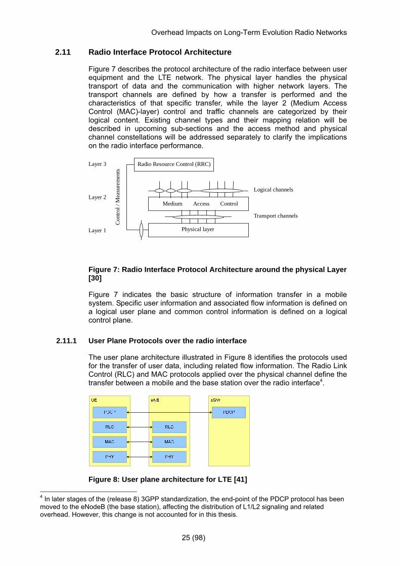
Figure 7 describes the protocol architecture of the radio interface between user equipment and the LTE network. The physical layer handles the physical transport of data and the communication with higher network layers. The transport channels are defined by how a transfer is performed and the characteristics of that specific transfer, while the layer 2 (Medium Access Control (MAC)-layer) control and traffic channels are categorized by their logical content. Existing channel types and their mapping relation will be described in upcoming sub-sections and the access method and physical channel constellations will be addressed separately to clarify the implications on the radio interface performance.
Radio Resource Control (RRC)
Medium Access Control
Transport channels
Physical layer
Con
trol /
Mea
sure
men
ts
Layer 3
Logical channelsLayer 2
Layer 1
Figure 7: Radio Interface Protocol Architecture around the physical Layer [30]
Figure 7 indicates the basic structure of information transfer in a mobile system. Specific user information and associated flow information is defined on a logical user plane and common control information is defined on a logical control plane.
2.11.1 User Plane Protocols over the radio interface
The user plane architecture illustrated in Figure 8 identifies the protocols used for the transfer of user data, including related flow information. The Radio Link Control (RLC) and MAC protocols applied over the physical channel define the transfer between a mobile and the base station over the radio interface4.
Figure 8: User plane architecture for LTE [41] 4 In later stages of the (release 8) 3GPP standardization, the end-point of the PDCP protocol has been moved to the eNodeB (the base station), affecting the distribution of L1/L2 signaling and related overhead. However, this change is not accounted for in this thesis.

Overhead Impacts on Long-Term Evolution Radio Networks
26 (98)
The functionality defined on layer 2 in the radio interface architecture includes Hybrid Automatic Repeat ReQuest (HARQ), multiplexing, scheduling and priority handling (handled by the MAC protocol); segmentation and ARQ (handled by the Radio Link Control (RLC) protocol); as well as header compression/decompression (using Robust Header Compression (ROHC)) and encryption using the Packet Data Convergence Protocol (PDCP) [42] (see Figure 9:). The encryption of control plane signaling can be performed in either the RAN or the core network depending on the type of control signaling.
Figure 9: The Structure for Layer 2 on the downlink [31]
For the downlink an asynchronous HARQ is currently assumed in ongoing 3GPP discussions, meaning that the downlink scheduler can select when to transmit retransmissions without having to notify the receiver in which frame the retransmission will occur. Consequently the RLC protocol will have to reorder incoming packets whenever they arrive out of order. However, on MAC level a one bit synchronous HARQ can be used as feedback as to whether the previous transmission was successful or not. This assumption will be used when discussing the control data overhead in upcoming sections.
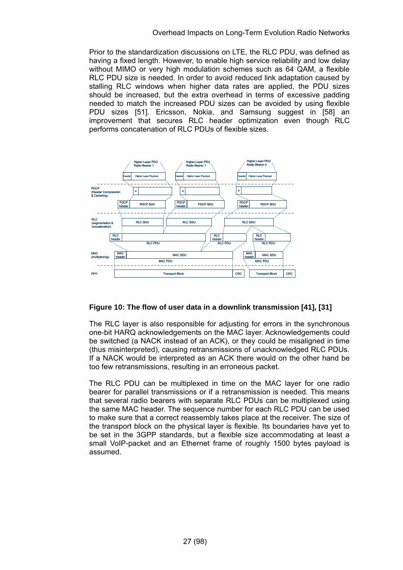
On the RLC layer, one can choose to acknowledge transmissions or not depending on the type of service (radio bearer) and the assumed reliability of the link. Services with requirements for low delays such as VoIP could be transmitted without acknowledgements, while a more delay insensitive service using larger packets (such as TCP traffic) could use acknowledgements for each packet. The RLC layer performs segmentation, and if necessary concatenations on packets from higher layers, creating RLC Packet Data Units with specific sequence numbers. If the radio environment should worsen considerably, further segmentation of the RLC PDUs is possible on the RLC layer. This process including the header compression stage is schematically described in Figure 10 below.
Overhead Impacts on Long-Term Evolution Radio Networks
27 (98)
Prior to the standardization discussions on LTE, the RLC PDU, was defined as having a fixed length. However, to enable high service reliability and low delay without MIMO or very high modulation schemes such as 64 QAM, a flexible RLC PDU size is needed. In order to avoid reduced link adaptation caused by stalling RLC windows when higher data rates are applied, the PDU sizes should be increased, but the extra overhead in terms of excessive padding needed to match the increased PDU sizes can be avoided by using flexible PDU sizes [51]. Ericsson, Nokia, and Samsung suggest in [58] an improvement that secures RLC header optimization even though RLC performs concatenation of RLC PDUs of flexible sizes.
PDCP SDU
Higher Layer Payloadheader
HPDCP(Header Compression& Ciphering)
PDCPheader
Higher Layer PDURadio Bearer 1
RLC SDU
MAC(multiplexing) MAC SDU
CRCPHY Transport Block
MACheader
Higher Layer Payloadheader Higher Layer Payloadheader
Higher Layer PDURadio Bearer 1
Higher Layer PDURadio Bearer 2
H H
PDCP SDUPDCPheader PDCP SDUPDCP
header
RLCheader
RLCheader
RLC SDU
RLCheader
RLC SDU
MAC SDUMACheader
CRCTransport Block
RLC PDU RLC PDU RLC PDU
MAC PDU MAC PDU
RLC(segmentation & concatenation)
Figure 10: The flow of user data in a downlink transmission [41], [31]
The RLC layer is also responsible for adjusting for errors in the synchronous one-bit HARQ acknowledgements on the MAC layer. Acknowledgements could be switched (a NACK instead of an ACK), or they could be misaligned in time (thus misinterpreted), causing retransmissions of unacknowledged RLC PDUs. If a NACK would be interpreted as an ACK there would on the other hand be too few retransmissions, resulting in an erroneous packet.
The RLC PDU can be multiplexed in time on the MAC layer for one radio bearer for parallel transmissions or if a retransmission is needed. This means that several radio bearers with separate RLC PDUs can be multiplexed using the same MAC header. The sequence number for each RLC PDU can be used to make sure that a correct reassembly takes place at the receiver. The size of the transport block on the physical layer is flexible. Its boundaries have yet to be set in the 3GPP standards, but a flexible size accommodating at least a small VoIP-packet and an Ethernet frame of roughly 1500 bytes payload is assumed.

Overhead Impacts on Long-Term Evolution Radio Networks
28 (98)
As the modulation and coding can be altered for different types of channels and services (or data streams if MIMO is deployed), the transfer and mapping of information between the L2 packet data units and the resource blocks on the physical layer need to be investigated. L1 overhead, channel coding (using turbo codes first descibed in [52]), and HARQ processing is applied prior to the mapping onto numerous assigned resource blocks, done by the resource scheduler. The scheduler subsequently decides on a common modulation scheme. The process will be examined further in an upcoming section (see Figure 12 on page 32). Following this procedure the data is subject to processing required for TX diversity, beam forming, and potential MIMO configurations. OFDM modulation is then applied to each of streams to be sent to the transmitting antennas.
2.12 Protocol Overhead Considerations
Figure 10 described how a transmitted IP packet is structured prior to transmission via the physical layer. Each protocol stage adds header information that is included in the transport block being subject to a cyclic redundancy check.
For speech services that require low delays, the RTP protocol is used along with UDP [38], [59]. In this thesis, RTP header information, the fixed UDP header, and the IP header are all together assumed to occupy 40 bytes in uncompressed mode.
PDCP enables compression of headers down to three bytes for most continuous flows, although the header compression in this thesis is assumed to be 5 bytes during DTX periods [44]. These three bytes are then assumed to include RTP, UDP and IP headers. Adding the PDCP protocol overhead for being octet aligned, adds another two bytes to the PDCP layer. However, use of fixed header sizes in PDCP is still being discussed in 3GPP for specific bearer services, such as a potential header size reduction for delay sensitive services such as VoIP.
Considering that several higher-layer resources can be concatenated and the potential re-arrangements needed for packets received out-of-order, the RLC-overhead can in general be assumed to consist of identification, re-segmentation, and reassembly information. For simplicity, the RLC layer is in this thesis assumed to handle only one block from the PDCP-layer, although multiplex of several blocks would be possible given Figure 10 and ongoing 3GPP discussions.
Recalling the discussions from [38] of necessary basic information contained in most protocol headers for identification, function, sequence number, and potential flags for out-of-order reassembly, the RLC header in this case could be assumed to be slightly more than 2 bytes long. As octet alignment is assumed on RLC/MAC level (and the MAC header later is defined in multiples of bytes), the exact number of RLC header bits is disregarded, and we will assume three bytes.
Since RLC PDUs from different bearer services can be multiplexed on MAC-level, the protocol overhead added is based upon their length and the level of multiplexing. Consequently, to accommodate this, another two bytes are assumed, leading to an overhead of five bytes.
Overhead Impacts on Long-Term Evolution Radio Networks
29 (98)
2.13 Multiplexing & Multiple Access
The definitions of future systems in the 3GPP standards make it possible to deploy LTE over various parts of the spectrum, as well as using variable bandwidths in adjacent cells or for different mobiles depending on spectrum allocations and service needs. The available spectrum bandwidths range between 1,25 MHz and 30,70 MHz ( [4], [35]) at different locations of the available spectrum. The more bandwidth allocated, the more sub-carriers can be deployed for downlink transmissions. However, currently the minimum bandwidth requirement for capability in the LTE mobiles is 20 MHz [31].
In the 3GPP LTE implementation of OFDM, a paired spectrum is supported by applying Frequency Division Duplex (FDD), enabling a separate frequency band to be used for multi-carrier downlink and single-carrier uplink transmissions.
The physical Layer in LTE uses a multiple access technique for the downlink based on OFDM called OFDMA, along with the use of a cyclic prefix. As the resource structure in Figure 11 on page 31 suggests, the frequencies are reused over time implying that time division multiplexing also is applied. Hence, resources are divided and shared in frequency as well as over time. This is the same concept as the existing GSM system where separate frequency spectra for uplink and downlink are allocated to multiple users over the same instances in time.
2.14 LTE Resource Blocks & Resource Elements
The standardized generic radio frame in an LTE downlink transmission is 10 ms in duration. Each radio frame is further divided into 20 slots, with a duration of 0.5 ms each. However, handling such small units on each sub-carrier of a bandwidth of 15 kHz would lead to considerable control data overhead in a transmission, which is why the concept of resource blocks was introduced [35]. A Resource block is a sub-band, a group of sub-carriers (defined to be 12 in [30]) used by one user for the duration of the slot. The maximum number of resource blocks over a given spectrum is referred to as NRU below. The signaling structure for LTE, discussed in later sections, is based on the slot duration of 0.5 ms (as shown in Figure 11), although the smallest TTI in recent 3GPP discussions has been determined to 1 ms, as a sub-frame consisting of two slots. This means that at least two resource blocks need to be used by each user during one TTI. For uplink transmissions these two resource blocks can be shifted in frequency so that frequency hopping can be applied. On the downlink the resource blocks need to be consecutive in both time and frequency [35] .
Overhead Impacts on Long-Term Evolution Radio Networks
30 (98)
The maximum number of sub-carriers equals NRU*12+1, divided equally among NRU resource blocks. The extra sub-carrier represents a fictive DC sub-carrier in the middle of the used spectrum. This sub-carrier is neither used nor transmitted, but used as a reference for some of the control signaling in the frequency domain. The resource blocks are assumed to be of constant size in current standardization discussions, which results in half of the resource blocks being distributed on either side of the DC carrier. If the number of resource blocks would be odd, this would result in the DC carrier splitting one resource block. The feasibility of such a solution where you would not always know the frequency position of a resource block, has yet to be fully investigated and decided upon in 3GPP standardizations. Even numbers of resource blocks will be assumed for the remainder of this thesis.
With spectrum allocations of different sizes, resource blocks at each end of the spectrum could be truncated. In order to use the entire spectrum and maximize the spectrum efficiency, one option would be to allow resource blocks of different sizes. However, since the 3GPP standards have yet to decide on the issue (as of December 2006), this document will assume resource blocks of a single fixed size unless specifically stated otherwise.
An additional radio frame structure different from frequency division multiplexing and multiple access exists for time-division multiplexing systems, where un-paired spectra are used for the up- and downlink transmission. However, that structure will not be referred to further within this thesis, nor will the related changes to the length of the cyclic prefix in a TDD system. Instead the FDD technique using paired spectra for the different links will be assumed.
Each transmitted FDD signal consists of one or several sub-carriers Nsc of 15 KHz bandwidth each, and a number Nsymbol of OFDM symbols. Each separate symbol interval on each sub-carrier is referred to as a Resource element in the 3GPP specifications [32], [35]. The relation between resource blocks, sub-carriers, OFDM symbols and resource elements is described in Figure 11.

Overhead Impacts on Long-Term Evolution Radio Networks
31 (98)
f
t
Cyc
lic P
refix
NS
Csub-carriers
Resource element:1 symbol
on 1 sub-carrier
Resource block
7 OFDM symbols
0.5 ms slot
Figure 11: Downlink Resources (Normal Cyclic Prefix Length)
The mapping above displays seven OFDM symbols in a resource block. The 3GPP standards stipulate the use of either six or seven OFDM symbols per resource block depending on the length of the cyclic prefix. The two fixed prefix lengths are configured by higher link layers depending on the multipath delay spread of each OFDM symbol. The extended cyclic prefix (applied within resource blocks with six OFDM symbols), is used in geographically larger cells with a larger delay spread or for the purpose of multi-cell broadcasting [4]. Noticeable for smaller delay spreads applying the normal cyclic prefix, is that the cyclic prefix length can have two predefined values, within the same resource block. [35].
As a result of the resource structure displayed above there will be 14*12 resource elements available for use during each TTI of 1 ms when the normal cyclic prefix length is used. These resource elements can and will carry payload data along with physical signaling information and the signaling required for resource allocation.
2.14.1 Transport Block to Modulated Signal
In case of a MIMO configuration where there are several streams of data in transmission, the process below of mapping transport blocks onto resource elements will be applied in parallel. Currently it is possible to deploy no more than two parallel processes as shown below, regardless of whether two or more parallel data streams are transmitted.

Overhead Impacts on Long-Term Evolution Radio Networks
32 (98)
HARQ &
Adaptive Coding
Rate
CRC
Transport block
Channel Coding
Physical Channel Mapping
onto Resource
Units
Selection of a common modulation
….
Resource unit assignments
Generation of complex values(scrambling)
Figure 12: Basic Modulation and coding of Resource blocks [27]
2.15 Channels and Signals
The LTE network and protocol architectures were discussed in previous sections, along with the basic resource structure of LTE. The upcoming investigation of different types of channels and signals in LTE will examine the details of information distribution, given these structures.
2.15.1 Logical Channels
Control channels are used for to describe logical control information content on the MAC-layer above the physical layer. The control channels are:
• Broadcast Control Channel (BCCH), a logical downlink channel for broadcasting system control information.
• Paging and notification Control Channel (P(N)CCH), a logical downlink channel transferring paging information or MBMS notifications when a mobile is to be located.
• Common Control Channel (CCCH), a channel used by mobiles having no radio resource connection with the network. At this point in time it has yet to be decided whether the network access mechanism should be handled on the CCCH or via L1 signaling. CCCH will be used for logical cell access content if the random access channel is defined as an uplink transport channel.
• Multicast Control Channel (MCCH), transmitting downlink scheduling and control information of to several users of MBMS.
Overhead Impacts on Long-Term Evolution Radio Networks
33 (98)
• Dedicated Control Channel (DCCH), a channel used in both uplink and downlink for dedicated control information once a radio resource connection between a mobile and the network has been established.
2.15.2 Traffic Channels
Traffic channels are used for transferring payload information. The traffic channels offered by layer 2 are:
• Dedicated Traffic Channel (DTCH), used to transfer user information to and from a mobile in dedicated mode.
• Multicast Traffic Channel (MTCH) used to transfer user information to several mobiles using MBMS.
2.15.3 Transport Channels
The logical content of a physical channel is defined on a higher layer as logical channels, and should not be confused with transport channels. The characteristics of a transfer and how it is performed define a transport channel. The physical transport channels used for downlink transmissions and some of their characteristics as defined in [31], are presented below;
• The Broadcast channel (BCH). This channel has pre-defined transport format that cannot be altered, and is required to be used over the entire area covered by cell in LTE.
• The Downlink Shared Channel (DL-SCH). Supports several Forward Error Correction techniques and dynamic link adaptation, since the modulation coding and transmitted power can be altered. Different types of resource allocations are also supported. These are discussed in a later section. This transport channel and its related control information are mapped onto the physical channel Physical Downlink Shared Channel (PDSCH).
• The Paging Channel (PCH). This channel is mapped to physical resources that can be used dynamically for other control channels or for traffic channels.
• The Multicast Channel (MCH). Used when transmitting information to several simultaneous users, creating the illusion that the same data is transferred from several cells, improving the reception conditions. [30]
Recalling Figure 12 it should be noticed that creation of complex values based on the symbols can be applied differently depending on the type of the transport channel. The broadcast and paging channels will have cell specific scrambling since they are intended for the entire cell. The downlink shared channel can have either a specific scrambling applied related to one single or a group of users. The MCH channel used for MBMS purposes will use scrambling that is specific to a cell or a group of cells intended for the MBMS transmission.
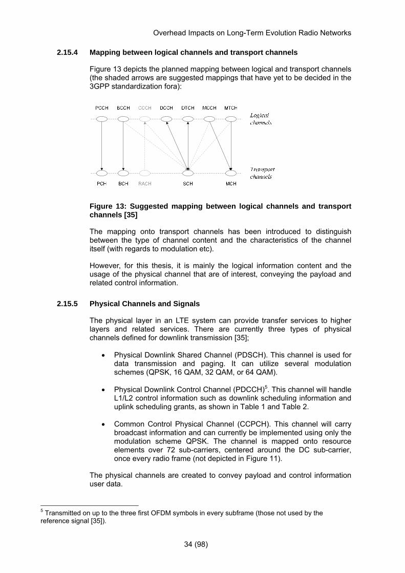
Overhead Impacts on Long-Term Evolution Radio Networks
34 (98)
2.15.4 Mapping between logical channels and transport channels
Figure 13 depicts the planned mapping between logical and transport channels (the shaded arrows are suggested mappings that have yet to be decided in the 3GPP standardization fora):
Figure 13: Suggested mapping between logical channels and transport channels [35]
The mapping onto transport channels has been introduced to distinguish between the type of channel content and the characteristics of the channel itself (with regards to modulation etc).
However, for this thesis, it is mainly the logical information content and the usage of the physical channel that are of interest, conveying the payload and related control information.
2.15.5 Physical Channels and Signals
The physical layer in an LTE system can provide transfer services to higher layers and related services. There are currently three types of physical channels defined for downlink transmission [35];
• Physical Downlink Shared Channel (PDSCH). This channel is used for data transmission and paging. It can utilize several modulation schemes (QPSK, 16 QAM, 32 QAM, or 64 QAM).
• Physical Downlink Control Channel (PDCCH)5. This channel will handle L1/L2 control information such as downlink scheduling information and uplink scheduling grants, as shown in Table 1 and Table 2.
• Common Control Physical Channel (CCPCH). This channel will carry broadcast information and can currently be implemented using only the modulation scheme QPSK. The channel is mapped onto resource elements over 72 sub-carriers, centered around the DC sub-carrier, once every radio frame (not depicted in Figure 11).
The physical channels are created to convey payload and control information user data.
5 Transmitted on up to the three first OFDM symbols in every subframe (those not used by the reference signal [35]).

Overhead Impacts on Long-Term Evolution Radio Networks
35 (98)
A potentially additional channel to those presented thus far, conveying HARQ ACK/NACK responses, has been under discussion in 3GPP. The exact details of the implementation of physical channels and signals has yet to be defined in the 3GPP standards [35].
As was discussed in section 2.15.4 for logical and transport channels, the number and exact definition of channels defined is not necessarily relevant when investigating the usage of physical channels, as long as a channel’s or signal’s relative energy consumption and impact on service performance can be quantified.
Not all resource elements in a resource block can be used for information transmission, since broadcast information and the two physical signals reference signal and synchronization signal (comprised of a primary and secondary signal) have to be allocated specific resource elements in a resource block. These signals are not mapped onto any physical channel, but should be handled separately. Further discussions of the physical channel mapping have been omitted in this thesis to concentrate on the signals transmitted and the different modulation techniques applied to these signals. For simplicity, the physical channel notation will however still be used, assuming four physical channels including one for HARQ ACK/NACK feedback. These semantics should not be interpreted as standardized channel concepts, unless stated otherwise.
To save energy, resource elements that are unused (neither carrying a physical channel nor a physical signal) contain no energy [35] .
A physical downlink transmission is prepared in four steps, as partly shown in Figure 2; after scrambling bits are modulated so that symbols of complex value are generated [35]. These complex symbols are then mapped onto resource elements, and finally the complex-valued OFDM signal is generated for each physical antenna.
2.15.6 Control Information on the Downlink
As previously indicated, the necessary overhead on the downlink in LTE can in general be summarized as;
• broadcast information on the broadcast channel,
• primary and secondary synchronization signals,
• control information on layer one and layer two
• downlink scheduling information, and uplink grants
and
• one reference signal per transmitting antenna.
Overhead Impacts on Long-Term Evolution Radio Networks
36 (98)
For each of the potentially allocated OFDM spectra, there is a guard-band applied at each end to defend against adjacent spectra with interfering out-of-band or adjacent frequencies. For a spectrum allocation of 5 MHz a guard band of 10 % leaves 4.5 MHz or 300 sub-carriers of 15 kHz bandwidth each, to be used by sub-carriers transmitting payload and control information each 1 ms.
The broadcast channel, uses 72 sub-carriers centered around the DC carrier for 14 symbols once every radio frame of 10 ms. Remembering the resource element and resource block structure from Figure 11 on page 31, this results in 168 resource elements per resource block being used for every 10 ms. This also means that 24 percent of the bandwidth is transmitting broadcast information during ten percent of the time (2.4 % of the total bandwidth is used) when 4.5 MHz is allocated for sub-carriers excluding the guard spectrum.
The same constellation with 72 sub-carriers centered around the DC-carrier is utilized for the synchronization channel, consisting of two sub-signals; the primary and secondary synchronization signal. These synchronization signals however span over two symbols for two TTIs during one radio frame, instead of over all symbols as the broadcast channel. The primary signal is used to find the timing of the synchronization channel, but as the receiver could shift slightly in frequency, the second secondary signal is used to remedy this potential error as well as to provide some initial cell information.
The signals are transmitted over two symbols at two different TTIs during one radio frame [35]. This results in ~0.69 % of the bandwidth when 4.5 MHz is allocated for the sub-carriers (see below).
⎟⎟⎠
⎞⎜⎜⎝
⎛
×
××
−×
10272
perTTI
perframe
total
SC
SymbolslSynchSymbo
GuardbandBWBW
(eq. 2)
L1/L2 control channel information is transmitted in the beginning of each TTI (in resource elements not used by reference signalling) and provides information on who is to receive the next resource block and when and what kind of modulation is applied to that specific resource block. In the downlink, the L1/L2 control channels are also used to provide resource block information related to the uplink. Thus, the control information on layer one and layer two altogether convey downlink allocation details, information on the size of the transport blocks, modulation information, and scheduling of downlink transmissions. It also conveys grants for and acknowledgements of uplink transmissions [27]. Given the structure of resource elements the L1/L2 control channel overhead depends upon the number of scheduled users using the downlink as well as the uplink.
The amount of transmitted control information needed for scheduling depends on the number of users in the network as well as how often transmission as scheduled. Which scheduling procedure to chose is a very complex issue that could require a thesis in itself, which is why the scheduling options discussed in this paper primarily will focus on dynamic scheduling and persistent scheduling, although there are numerous variants thereof.
Overhead Impacts on Long-Term Evolution Radio Networks
37 (98)
Dynamic scheduling allocates resources at every transmission interval, every TTI, depending on channel requirements. When using small packets and allocating resources for every TTI whenever there is data available, the overhead will be considerable keeping in mind the short TTIs of 1 ms used for LTE. However, if DTX is deployed for a speech service, resources would not need to be scheduled for the periods in-between speech bursts, excluding silence indicator frames (SID-frames). This could significantly reduce the scheduling overhead.
Persistent scheduling - as the name implies - is a more static resource allocation method, allocating resources as long as there are bits to send, reducing the need for control signaling information. However, in the most extreme case of persistent scheduling, the scheduling information is sent once and resources are fixed during a pre-defined time interval; hence they cannot be changed based on altered channel conditions and coding rates. Potential retransmissions have to be accounted for during scheduling, which could result in that some of the scheduled resources never or very seldom will be used.
The scheduling signaling described in Table 1 and Table 2 (resource allocations, grants, and HARQ acknowledgements) will be required for each transmission when dynamic scheduling is applied. During persistent scheduling, HARQ acknowledgements are still transmitted every TTI, while the additional scheduling signaling can be transmitted less frequently.
Dynamic and persistent scheduling can be considered two extreme scheduling algorithms in terms of use of scheduling resources, both having advantages and disadvantages. The most likely scheduling scenario is presumably somewhere in-between, although outside the scope of this thesis. The deployment of DTX can be used to illustrate this statement; dynamic scheduling schedules resources every TTI, but when DTX is activated there is no need to allocate resource during DTX intervals of no speech activity (not considering SID frames). If dynamic scheduling is assumed, DTX periods of no speech would significantly reduce the necessary percentage of scheduling information, as discussed in section 4.3. The impact on total overhead of using either of the two scheduling algorithms, will be presented.
There are discussions ongoing in 3GPP to try to solve the obvious drawbacks of both dynamic and persistent scheduling methods (for instance to verify retransmissions before allocating resources with persistent scheduling), but as mentioned details on the subject are outside the scope of this thesis.
The reference signal provides a reference in order to obtain coherent demodulation at the mobile receiver. The signal is also used for channel quality estimation to improve link adaptation and scheduling that is dependent on the quality of the channel. It is transmitted once every 6th resource element in the frequency domain and on two out of seven OFDM symbols in the time domain (the first and third last OFDM symbol per each slot interval of 0.5 ms with an offset from the first reference symbol in the slot of three sub-carriers) [35]. This results in one resource element out of 21 being used for the reference signal in a configuration using the normal cyclic prefix without downlink diversity. Thus leading to an overhead of about 4.8 percent.

Overhead Impacts on Long-Term Evolution Radio Networks
38 (98)
One reference signal is used for each downlink transmit antenna, and 3GPP standards allow 1, 2, or 4 downlink transmit antennas. For two downlink antennas this results in a 2/21 (~9.5) reference signal percentage. From [35] it can also be concluded that half of these amounts are added when using three of four antennas (5/42 (~11.9) and 3/21 (~14.3 %) of overhead for the reference signals, see Table 3) .
Discussions in the 3GPP standards are currently evaluating whether to suggest a power boost on reference signal information whenever applicable. Stronger reference signals in the downlink would enable better coverage or lower sensitivity requirements on mobile receivers.
Increasing the power of the reference signals by for instance 3 dB would mean that twice as much power is spent on conveying control information using 1/21 of system resources in a single antenna configuration (see Table 1).
Let ( )
espeechframPowercommonOH *1−
(eq. 3)
represent the power that is used to convey payload and speech frame overhead. CommonOH represents energy spent on reference signals, synchronization signals and broadcast information.
Secondly, let commonOHrefsignal
(eq. 4) represent system overhead power for reference signals. A 3 dB increase in reference signal power (twice the energy level) would then mean that the relative energy spent on commonOH would increase by said factor. The power left for payload and related overhead would then decrease by a factor
commonOH
commonOHcommonOH
refsignal
−
⎟⎠
⎞⎜⎝
⎛⎟⎠⎞
⎜⎝⎛ +−
1
*11
(eq. 5)
if the available power resources remain constant (see Figure 15).
The signal/-s is/are mapped onto the resource elements as shown in Figure 11, depending on the length of the cyclic prefix. Since the extended cyclic prefix uses a different number of OFDM symbols per TTI, the placing of the reference symbols in the time domain is adjusted accordingly, for instance when the system is designed to handle larger cells and more extensive multipath delays.
In a one-antenna transmit system every 6th or 5th resource element is used for the reference signal, when applying a normal or extended cyclic prefix respectively. For systems using two or more transmit antennas, the mapping of the reference signal onto resource elements and its impact on system performance is more complex as described in [35].
Overhead Impacts on Long-Term Evolution Radio Networks
39 (98)
Downlink paging has not yet been standardized; hence this has been omitted from this thesis in order to simplify our analysis. However, one could assume that the structure used for transferring paging messages is similar to that of broadcast information, although this does not mean that the paging load will be the same. Paging load is heavily dependent on traffic load and the core network and base station capacities to convey paging commands.
2.16 Control Channel Transmit Diversity
Potential downlink diversity gains for control channels are addressed specifically in [27], since diversity improvements for control channels specifically, through retransmissions and link adaptation, are deemed difficult. Although a number of open-loop diversity techniques are suggested for further evaluation, cyclic delay diversity is assumed for L1/L2 control information using either two or four downlink transmit antennas.
2.17 MIMO
MIMO enables the use of the use of multiple streams and improved diversity. In addition to a basic MIMO configuration of two antennas at the transmitter and one or several at the receiver respectively, four Tx antennas deployed using either two or four RX antennas should also be considered as plausible MIMO configurations to obtain higher diversity gains [27].

Overhead Impacts on Long-Term Evolution Radio Networks
40 (98)
3 Previous Studies
3.1 Expectations of LTE
A number of techniques to achieve the proposed performance figures using the LTE concept are proposed and evaluated in [18]. This report also examines new radio transmission technologies intended for deployment beyond LTE. The latter can hopefully simplify the suggested technical solutions for LTE even in future radio access networks.
Although the suggestions mainly are focused on LTE, the performance of some WCDMA/HSPA improvements is shown to be equal to LTE. However, the LTE improvements for layer one, including broadcasting and spectrum flexibility, are still advantageous [27], [30].
For a basic description of suggested Long-Term Evolution improvements, see section 1.2 and [19]. Further details and historical background on the ongoing LTE standardization can be found in [28], [20], [31], and [32].
3.1.1 Frequency Reuse
Although the use of a specific frequency has been the focus of many studies on frequency reuse designs historically, frequency reuse is not directly related to how a channel can be allocated in an LTE mobile system. LTE is targeting packet data users that can use different amounts of the available bandwidth among the users competing for the same resources. Constant levels of interference and fixed allocations of specific resources, as with circuit-switched voice calls in a GSM system, are no longer applicable.
There are a number of different frequency reuse patterns that can be used in an LTE radio access network, and the usefulness of these frequency allocation schemes all depend on the amount of available spectrum, the allocation or scheduling strategies (how efficiently the spectrum is utilized), the use of power, and the system’s ability to handle or suppress the interference introduced. In [11], a number of variants of classical reuse patterns, adjusted for an LTE RAN with packet-switched services, are discussed and evaluated.
A frequency reuse of 1, i.e. using the same frequencies in all cells, is shown to be most effective among reuse patterns considering only downlink performance. However, interference between the cells in such a scenario is an issue that needs to be dealt with. Inter-cell interference will affect resources that can be scheduled successfully. Hence, the useful bandwidth or the maximum output power is reduced.
The total system throughput is estimated for two use-cases in [11]; one where the users use different amounts of data and one where the users consume exactly the same amount of data but during an extended time period. For the first case, the system throughput will mostly be used by users experiencing good radio conditions. The latter case corresponds to a service where files of a specific size are downloaded.

Overhead Impacts on Long-Term Evolution Radio Networks
41 (98)
The estimated link bitrate is measured from two perspectives; when the system is used for a constant period of time, and when a specific amount of data is downloaded over different time periods. However, in the case where users are evenly distributed over a larger area, the fixed-data scenario is not particularly representative. As users experiencing bad radio conditions need to stay longer in the system to complete a transfer, even more users will be gathered in areas with poor radio conditions and hence suffer more from downlink interference.
Two different antenna configurations are evaluated, using a single antenna and MIMO (2*2). Transmission diversity was used on the downlink, and upon reception of the signals, the combining techniques MRC and IRC have been used.
3.1.2 Peak-to-Average Reduction (PAR)
In [12], solutions on how to reduce the high inherent peak-to-average ratios in an OFDM system are investigated. As highlighted in both [12] and [6], the definition of the PAR is the maximum of the absolute value squared, divided by the expectation of the absolute value squared:
})({
})(max{)}({ 2
2
tyE
tytyPAR = (eq. 6).
From the OFDM signal representation during one general symbol interval n as defined in [6]:
∑−
=
−=−1
0
)(2)(1)(N
m
nTtfjm
mencT
NTty π , (eq. 7)
where t is the time instant, N the number of sub-carriers, Cm the symbol, and T the period,
and the signal expectation })({ 2tyE
∑∑−
=
−
=
− =1
0
1
0
)(21
1)}()({11
N
M
N
l
tffjjm N
TencncE
Tmπ , (eq. 8)
it can be concluded that the level of the PAR is directly proportional to the number of sub-carriers N. The more sub-carriers used in a transmission, the larger the PAR will be at the receiver.
However, this conclusion relies on the fact that information symbols are perfectly uncorrelated in time and that the symbol energy is of constant amplitude but varying phase [6].
Overhead Impacts on Long-Term Evolution Radio Networks
42 (98)
3.1.3 Downlink Power Consumption
In [3], different approaches are investigated to describe the energy transmitted in the downlink. The first technique defines an interference area based on the Okumura-Hata propagation model in a GSM system. The relative size of the interference area is used to indicate the introduced interference in downlink. Another measure defines the transmitted energy based on how much of the available channel quantity is used.
M. Ericson, et al. describes an equation that defines the total power used in a downlink in a WCDMA system [36], and S. Wänstedt et al., concludes that services using very small packets of data such as VoIP, suffers from the extensive overhead information in a WCDMA/HSDPA system [37]. Retransmissions are considered with regards to their impacts on capacity and the carrier-to-interference ratio. However, it remains to be investigated whether the restrictions of transferring small data packets also are applicable to LTE, given the structure of the overhead of data transmissions.
Recalling the discussion on channel structures from section 2.11, and discussions on resource handling within a resource block, the total power transmitted can be summarized as power on a physical channel used to transmit payload data along with power used to transmit control information. To describe the total transmitted downlink energy, the transmitted power is calculated as a function of the number of resource blocks in a cell, given all traffic and control channels used during a TTI. It is assumed that all base stations use the same total power in the downlink and that the system is interference limited. The latter implies that relatively small cells are used which renders noise interference insignificant. A similar calculation is performed in [36] to describe the distribution of downlink power in a mixed services WCDMA network.
As the total transmitted energy is the sum of all transmissions on all sub-carriers in an OFDM resource block, the total transmitted energy over a cell coverage area from one base station bs can be described as
( )
CCPCHPDCCHPDSCH
pagingschrefbchN N N
schedbsRUbstot
PPP
PPPPPPPRU SCHEDUSERS SCHEDLINKS
DL
++=
+++++=∑ ∑ ∑,
(eq. 9)
where NRU is the number of resource blocks defined in a cell.
Noticeable for the paging channel in LTE is that the paging procedure is similar to that of GSM/EDGE with defined paging groups where the handsets listen for paging requests at regular intervals and save power during the time in between these occasions. The downlink notification deployed in WCDMA/HSDPA systems is not used, since the time when the paging group is scanned for information by reading control information is very short due to the sub-frame structure in an LTE network.
An estimated SINR target at the receiver, for the resource block RU could then be described as follows, given that the power transmitted from a base station bs is PbsRU:

Overhead Impacts on Long-Term Evolution Radio Networks
43 (98)
( ) 0,, NIGPGP
iotherRUsbsRUbstotRU
bsRUbsRUDL
iDLi
ii
i ++=Γα
(eq. 10).
3.1.4 Scheduling
Apart from dynamic and persistent scheduling, another common scheduling principle is the Proportionally Fair in Time and Frequency (PFTF) technique investigated in [39]. This scheduling technique not only considers the time used, but also the frequency allocation.
Optimized scheduling principles have yet to be agreed on for the 3GPP standards. The advantages and disadvantages of persistent scheduling are discussed in [54] [55], and [62]. Semi-dynamic scheduling is examined in [56], and blind detection without impacting L1/L2 signaling is described in [57], along with an overview of various mechanism for downlink scheduling as of December 12 2006.
Discussions as of late February 2007 are focusing on semi-dynamic scheduling and blind detection, with the main purpose to prevent L1/L2 signaling from restricting capacity. More references on the subject of scheduling can be found in [61].
3.1.4.1 SINR Requirements
When assuming round-robin scheduling, the arrival probability of a packet to be scheduled for an AMR speech frame can be described as in [36] (this also describes the subsequent reasoning concerning SINR requirements per user subject to scheduling):
msms
ngthAMRFrameLeTTITTI
201
===λλ
This only describes the likelihood of a packet arriving at the scheduling queue. The actual transmission of the packets depends on the chosen scheduling algorithm and the load in the system in terms of multiplexed users and users in one cell.
Given that an assumed 10 % guard band is applied to the available spectrum and that 12 sub-carriers of 15 kHz bandwidth are allocated to each resource block, the spectrum available for scheduling during each TTI is 90.0×BW
MHz divided among M users where M equals
( )
1215
90.0kHz
BWMHz ×
, assuming one resource block per user.
The time between each complete transmission of a packet depends on the number of users M and the multiplexing factor mux. Thus the number packets aggregated (when M is large) and the average sent to one user can be described (based on [36]) as

Overhead Impacts on Long-Term Evolution Radio Networks
44 (98)
( )muxMnE λ=
. (eq. 11)
Assuming that a packet of an RLC PDU frame size requires a specific SINR, one can assume that a packet size equal or close to multiples of an RLC PDU will require multiples of the required SINR. The total SINR requirement can then be estimated to be
mDLmDLtotDL muxMn Γ=Γ=Γ λ
(eq. 12)
as is done in [36].
3.1.5 Retransmissions
As noted in [37], it is necessary to establish a fast feedback link on layer 2 since the channel estimations made from the transmitted downlink information will be offset by a number of TTIs.
In addition to retransmissions due to erroneous (too slow) feedback on the channel quality, these could also occur if a mobile experiences a low SINR or high inter-cell interference. In those cases the power available as shown in the previous section can only cater for a fraction of the n packets that can be transmitted using the power available. Alternatively packets could be retransmitted a number of times and decoded by the receiver using Chase Combining. In both [36] and [37] these two retransmission aspects are considered equally common and the increased number of packets has been defined as
( )combchasedelayfeedbacktotal retransretransmuxMn __ βλ +=
(eq. 13)
where combchaseretrans _β denotes the fraction β of all the users that experience bad coverage multiplied by the number of total transmissions (including the first one) needed for a successful reception, given chase combining.
The number of possible retransmissions depends on the performance requirements of a given service. The longer delay a service can accept, the more retransmissions can be allowed. However, the maximum number of such retransmissions without exceeding delay requirements are dependent on the interval between them, which in turn is dependent upon the number of users in the system, from equation (6) above [37]. If the delay threshold is defined in terms of number of complete packets of a predefined size, and related to the total number of packet transmissions ntotal the maximum number of retransmissions (including the first one) can be described as in [36] and [37]:
total
packetscombchase n
delayMaximumretrans
__ =
(eq. 14)
Overhead Impacts on Long-Term Evolution Radio Networks
45 (98)
As discussed in [37], the transmission of multiple packets of a certain size without retransmissions will require a SINR multiplied by the SINR required for the transmission of one such packet. Considering retransmissions, we now know that each transmission before successful decoding is defined as 1/retranschase_comb. The total SINR including retransmissions can then be defined as the packets transmitted until successfully received multiplied by the SINR of each transmission
packets
mDLtotal
total
packets
mDLtotal
combchase
mDLtotaltotDL
delayMaximumn
ndelayMaximum
nretrans
n
_
_
2
_
Γ
=Γ
=Γ
=Γ
(eq. 15)
From this formula it can be seen that when considering retransmissions, the required SINR is proportional to the square of transmitted packets. It can also be seen that additional retransmissions reduce the required SINR (left part of the formula), as well as increase the need for SINR as more packets are transferred (the left part of the formula). However, simulations referred to in [36] have shown that retransmissions as defined in [36] and [37] overall decrease the need for SINR.
The inherent delays in a mobile system have resulted in that the modulation and coding scheme selection initially is based on an estimation of the average link quality, rather than direct feedback from CQI information contained in transfer and reception buffers.
3.1.6 LTE Downlink Performance
Given previous discussion during the 3GPP standardization activities, the uplink can in most cases be considered as the limiting link, and the control channels are potential bottlenecks in terms of LTE coverage at maximum traffic load.
In [13] the basic LTE downlink throughput for data services using OFDM is compared to the throughput of 3GPP release-6 HSDPA. The introduction of more complex antenna solutions (MIMO) are also examined. Simplified models are used for the physical and MAC layers. Potential performance improvements such as shorter round-trip-times, based on higher layer protocol improvements, were not accounted for.
The conclusions are that the main contributors to increased throughput for LTE are the introduction of several data streams deployed through MIMO configurations. In this comparative study, scheduling, link adaptation, and power control in the frequency domain have not been included, which all could improve the relative performance of LTE. Nor has the potentially wider spectrum for LTE (using a larger number of sub-carriers) been considered. The spectrum used in the study was 3.84 MHz.
Overhead Impacts on Long-Term Evolution Radio Networks
46 (98)
3.2 3GPP LTE Standardization
3.2.1 Scheduling Overhead
As the 3GPP standardization is continuously ongoing until the third quarter of 2007, [32] should be referenced for more recent updates. However, in [27] suggested bit structures for scheduling and feedback information are presented, dividing the dedicated bit allocation into three different categories of downlink scheduling (Table 1), and into resource assignment information and transport format data for uplink scheduling grant information (see Table 2). The synchronous acknowledgement feedback on the downlink is assumed to be one bit per uplink transport block when using one data flow in the uplink per user [27]. As the details of the control channel properties have yet to be finalized in the 3GPP standardization, the following figures are only a presentation of ongoing discussions. Further details are presented in [27]. Based on [45], the first parts of the message, including the identification of a mobile and the transport format (see Table 1), can be assumed to be about 40 bits. Depending on the chosen scheduling mechanism, these information bits can be sent for every transmission, for every session, or scheduled in many other ways. The HARQ indicates the status of the earlier transmission using 6 bits and is needed for every transmission. The scheduling grant content which is based on uplink transmission, is discussed in [41] and [46] and assumed accordingly in these discussions, even though the final decision on scheduling content for LTE has yet to be taken. Thus about 36 bits cater for resource assignment of scheduling grants and additional two bits for synchronous uplink HARQ sequence numbers. Presented bit configurations are assumed to reflect maximum system scheduling capacity. However, the bit size fields have been omitted in Table 1, Table 2, since the tables only present suggested formats, leaving the details of implementation for finalized 3GPP standards.

Overhead Impacts on Long-Term Evolution Radio Networks
47 (98)
Table 1: Downlink Scheduling Information [27]
Category Field
ID
Resource assignment
Resource Indication
Assignment duration
Multi-antenna info.
Modulation scheme
Transport Format
Payload size
HARQ process no.
Redundancy version
Asynch. HARQ
New data indicator
Hybrid ARQ
Synch. HARQ
Retransmission sequence no.
Table 2: Uplink Scheduling Grant [27]
Category Field
ID
Resource assignment
Resource Assignment
Assignment duration
Transport Format Transmission parameters

Overhead Impacts on Long-Term Evolution Radio Networks
48 (98)
3.2.1.1 Transmission Schemes
In [16] two types of LTE downlink resource allocation schemes, block-wise and scattered transmission, are handled based on previous related discussions in the 3GPP standardization body. A block is here defined as the number of sub-carriers dedicated to one particular user. The discussion is focused on how to optimize the use of consecutive sub-carriers and OFDM symbols for each user, the design of diversity transmission, multiplexing, and how to maximize the efficiency of signaling overhead. If more users are sharing the available sub-carriers, the CQI overhead increases. This paper also concludes that neither channel dependent scheduling nor link adaptation is suitable for very fast channel variations, e.g. when mobile handsets are used in cars going on a highway. The data rate performance is reduced when more high-speed users are introduced into the system. The user with the highest SNR simply cannot be selected if the channel varies too fast to be estimated, disabling diversity gains over several users at high speeds. Trying to remedy this situation, a transmission scheme, aiming at maximum time- and frequency diversity for a single packet transmission, is presented. Block-wise and scattered transmissions are compared, and simulation results show that diversity transmissions per sub-carrier, provides better performance than using block-wise diversity for high-speed users. For low-speed users the results are reversed, showing high throughput gains for block-wise transmission. However, an interesting observation is that the signaling overhead indicating the resources to use for transmission remains the same.
Although these two methods (in simulation) show conclusive results for these transmission techniques with users at different speeds, the former, also known as localized transmission has been agreed on in the 3GPP standardization due to extensive time dispersion when using scattered transmission.
3.3 Potential Standardization Improvements
3.3.1 Modulation Improvements
In [4] the OFDM modification CP-OFDM is used. This technique, further described in section 2.7, potentially removes all inter-symbol and inter-carrier interference (ISI and ICI), minimizing subsequent system performance degradation. However, the use of a cyclic prefix requires a prefix size in tune with channel properties and requires extensive overhead data transmission. Both pilot symbols (used to estimate the channel in question), and the cyclic prefix itself need to be transmitted.
The concerns for the properties of the cyclic prefix have resulted in studies on modifications of the OFDM technique. There are a number of studies striving to improve the frame time and frequency offset estimation needed for OFDM. In [5] the use of number of time-domain pilot signals (using dedicated binary synchronization patterns) is presented as a synchronization alternative to the cyclic prefix. The synchronization patterns are alternated between OFDM symbols. However, the gain from omitting the cyclic prefix has not been evaluated using faded channels.
Overhead Impacts on Long-Term Evolution Radio Networks
49 (98)
The PRP-OFDM technique first presented in [7] uses a postfix instead of a cyclic prefix. The procedure, further evaluated in [6], still uses some overhead information, but drastically reduces the need for pilot symbols. PRP-OFDM can potentially increase spectral efficiency at the same as the system performance is increased or at least remains the same as for a system using CP-OFDM. However, the major drawbacks of using PRP-OFDM are the increased system complexity and the introduction of both ISI and ICI. This technique has mainly tested and evaluated a WLAN implementation from a performance improvement perspective, i.e. increasing data throughput with improved mobility and performance. Its complexity has to be drastically reduced in order to achieve an implementation for use in a mobile cellular system. [6]
3.3.2 Frequency Error Sensitivity6
A technique called Polynomial cancellation coding (PCC) is proposed in [8] to reduce the sensitivity to frequency errors in an OFDM system. Effects on fading characteristics and the error performance are investigated, although only for a two-path fading channel. PCC is said to improve error performance in OFDM with lower sensitivity to large delay spreads, at the expense of lower spectral efficiency. However, when combining PCC effects with those of channel coding and the cyclic prefix, the spectral efficiency is said to be comparable to that of OFDM. This technique remains to be investigated in a multi-user multi-path fading system.
6 As detailed evaluation of OFDM impairments are outside the scope of this thesis, this section should be considered orientation on potential further standardization.

Overhead Impacts on Long-Term Evolution Radio Networks
50 (98)
4 Radio Network Model: Assumptions & Parameters
4.1 Link Performance Model Definition
In all packet oriented radio access technologies, the service bitrate is adapted to the quality of the radio link through link adaptation. The radio link quality will thus affect the transmission time for data packets of a given size. Not considering potential delays, the system capacity will thus be restricted by channel utilization, which will be defined by transmission time for a number of parallel users over a given bandwidth.
The normalized measure discussed to investigate energy consumption in section 1.4, [Ws/Mbit], would be an appropriate assumption for the cost of energy, if power is equal to the cost of radio resources. This is generally applicable to systems where intra-cell interference dominates (such as WCDMA, deploying code division multiplexing). However, for OFDM systems where orthogonality is dominant within a cell, propagation losses will reduce the interference (in this case mostly inter-cell interference), and consequently propagation loss will dominate the cost of power. A loss factor should be added when modeling the link performance. As the working assumption in the 3GPP standards prerequisites for improved link performance for LTE, bit-rates close to the Shannon link performance model can be modeled, given a loss factor. It should be noted that a different model than Shannon could be more appropriate to accommodate delays, if link delays are large relative to the service delay. Such a situation would require extensive system simulations.
The model applied in this thesis assumes relatively small link delays, but instead accommodates retransmissions. The energy required is thus calculated with regards to the worst-case scenario in terms of resource consumption during a transfer.
As frequency reuse considerations for LTE in many aspects are similar to those for the existing GSM system, basic assumptions on the use of channel resources can use those valid for a GSM system when applying tight frequency reuse, given that the higher frequency range and specific resource structure in LTE is accounted for. As LTE also applies an FDMA as well as an TDMA structure for radio transmissions, the same reasoning could be used for radio issues in an interference limited LTE system with reasonably high load where the frequency reuse pattern could be assumed to be similar, if not actually the same [11].
The link performance model assumed in this thesis has been determined in a LTE system simulator with 100 % traffic load and a frequency reuse of one (all frequencies used in all cells). Figure 14 shows the cumulative distribution function of this model with a loss of ~20 % using 16 QAM as modulation technique in a system with a site-to-site distance of ~1 km.
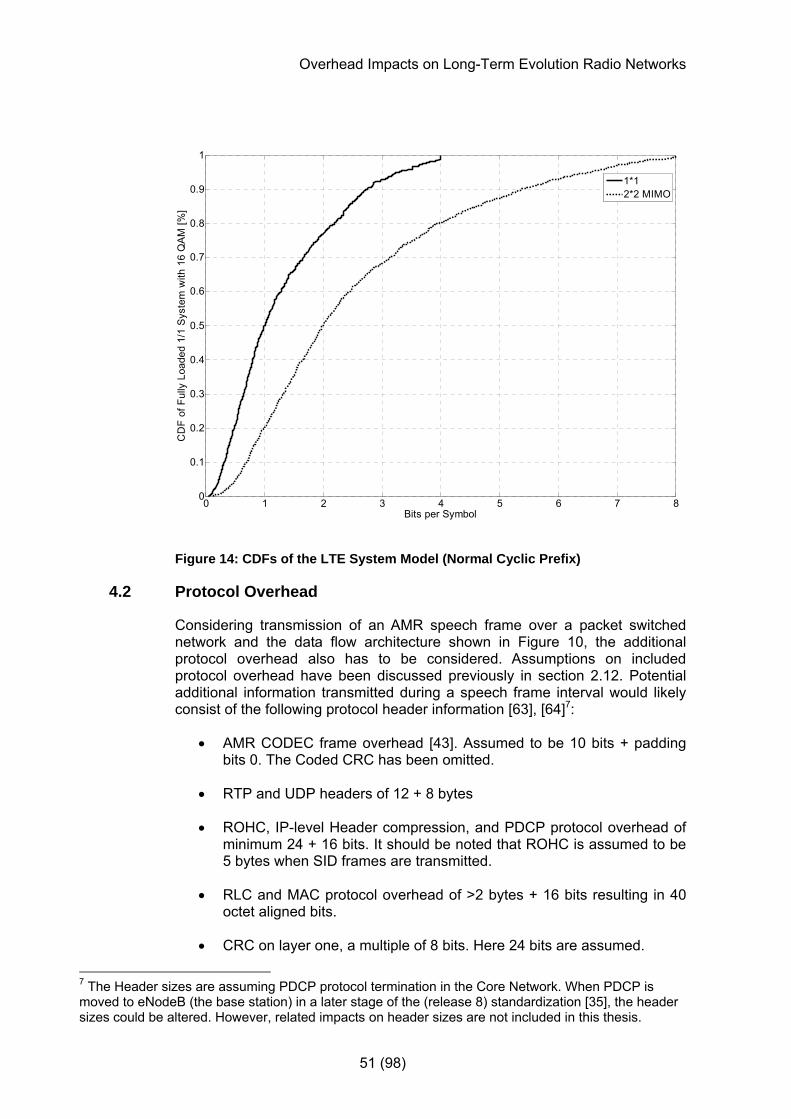
Overhead Impacts on Long-Term Evolution Radio Networks
51 (98)
0 1 2 3 4 5 6 7 80
0.1
0.2
0.3
0.4
0.5
0.6
0.7
0.8
0.9
1
Bits per Symbol
CD
F of
Ful
ly L
oade
d 1/
1 S
yste
m w
ith 1
6 Q
AM
[%]
1*12*2 MIMO
Figure 14: CDFs of the LTE System Model (Normal Cyclic Prefix)
4.2 Protocol Overhead
Considering transmission of an AMR speech frame over a packet switched network and the data flow architecture shown in Figure 10, the additional protocol overhead also has to be considered. Assumptions on included protocol overhead have been discussed previously in section 2.12. Potential additional information transmitted during a speech frame interval would likely consist of the following protocol header information [63], [64]7:
• AMR CODEC frame overhead [43]. Assumed to be 10 bits + padding bits 0. The Coded CRC has been omitted.
• RTP and UDP headers of 12 + 8 bytes
• ROHC, IP-level Header compression, and PDCP protocol overhead of minimum 24 + 16 bits. It should be noted that ROHC is assumed to be 5 bytes when SID frames are transmitted.
• RLC and MAC protocol overhead of >2 bytes + 16 bits resulting in 40 octet aligned bits.
• CRC on layer one, a multiple of 8 bits. Here 24 bits are assumed.
7 The Header sizes are assuming PDCP protocol termination in the Core Network. When PDCP is moved to eNodeB (the base station) in a later stage of the (release 8) standardization [35], the header sizes could be altered. However, related impacts on header sizes are not included in this thesis.

Overhead Impacts on Long-Term Evolution Radio Networks
52 (98)
For a voice service that requires low delay, it is advisable to deploy the RTP protocol [38], along with the UDP protocol instead of the TCP protocol that requires more complex acknowledgement procedures [59].
The compression of packets can differ depending on the type of protocols used, and packet errors that require the decompression context to be updated. However, a constant minimum IP-level compression overhead of 3 bytes is assumed for the speech services considered in this thesis. These 3 bytes include IP-header, RTP, and UDP headers.
For a voice service it is assumed that discontinuous transmission is deployed in a mobile system such that 40 % of the speech frames do not contain user payload (the user is silent), i.e. the voice activity factor (VAF) is 100% - 40 % = 60 %.
For packets of different sizes the transport block size will be different. For a TCP/IP transfer using a total packet size of 1500 bytes, of which 1460 bytes are payload, the additional header information would consist of an additional 20 byte TCP header, and 20 bytes for the uncompressed IP header (assuming no header options). In some implementations with large packets it could be advisable to avoid IP header compression in order to avoid unnecessary system complexity since the gain of using header compression is smaller when using larger packet sizes. A successful decoding of ROHC compressed IP headers could require information from previously transmitted bits, which could result in packets being lost during subsequent decoding of the compressed header information.
Assuming no header compression for a TCP/IP transfer, the protocol overhead would be 20 bytes for the IP header and 20 bytes for the TCP header, apart from the PDCP, RLC/MAC, and CRC headers already mentioned. Thus, the addition to the transport block with a compressed IP header of 3 bytes, would be an additional 20 bytes for the TCP header, in total 37 bytes (or 57 bytes if 20 bytes of TCP header options are assumed).
4.3 Scheduling Overhead
Assuming that all control signaling for scheduling have the same modulation rate as the PDCCH (QPSK), and turbo coding with channel rate 1/3, one can investigate the control signaling overhead for downlink transmissions as in Table 3.
The downlink resource assignment information and the uplink scheduling grants transferred on the PDCCH can for simplicity reasons initially be assumed to be around 40 bits as previously discussed8. As defined in [35], the PDCCH is transmitted on up to the three first symbols during a TTI except on the resources elements used for reference signaling9. The maximum number of PDCCHs per TTI can then be calculated as
8 This size of 40 bits was mentioned in [48], although it is still under discussion in the 3GPP standardization. In this thesis 46 and 38 bits are assumed for downlink assignments and uplink scheduling grants respectively. 9 The reference signal is transferred as described in section 2.15.6. Every sixth frequency is used on two symbols out of every 7 symbols.
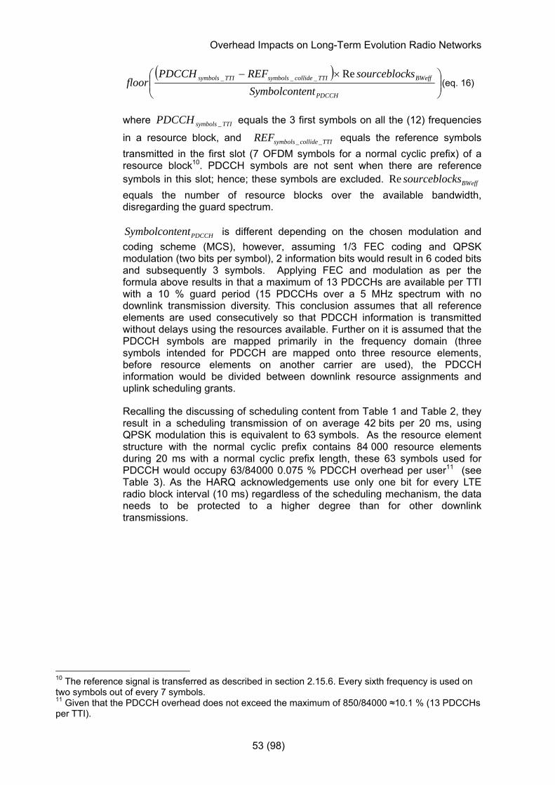
Overhead Impacts on Long-Term Evolution Radio Networks
53 (98)
( )⎟⎟⎠
⎞⎜⎜⎝
⎛ ×−
PDCCH
BWeffTTIcollidesymbolsTTIsymbols
entSymbolcontkssourceblocREFPDCCH
floorRe___ (eq. 16)
where TTIsymbolsPDCCH _ equals the 3 first symbols on all the (12) frequencies
in a resource block, and TTIcollidesymbolsREF __ equals the reference symbols transmitted in the first slot (7 OFDM symbols for a normal cyclic prefix) of a resource block10. PDCCH symbols are not sent when there are reference symbols in this slot; hence; these symbols are excluded. BWeffkssourceblocRe equals the number of resource blocks over the available bandwidth, disregarding the guard spectrum.
PDCCHentSymbolcont is different depending on the chosen modulation and coding scheme (MCS), however, assuming 1/3 FEC coding and QPSK modulation (two bits per symbol), 2 information bits would result in 6 coded bits and subsequently 3 symbols. Applying FEC and modulation as per the formula above results in that a maximum of 13 PDCCHs are available per TTI with a 10 % guard period (15 PDCCHs over a 5 MHz spectrum with no downlink transmission diversity. This conclusion assumes that all reference elements are used consecutively so that PDCCH information is transmitted without delays using the resources available. Further on it is assumed that the PDCCH symbols are mapped primarily in the frequency domain (three symbols intended for PDCCH are mapped onto three resource elements, before resource elements on another carrier are used), the PDCCH information would be divided between downlink resource assignments and uplink scheduling grants.
Recalling the discussing of scheduling content from Table 1 and Table 2, they result in a scheduling transmission of on average 42 bits per 20 ms, using QPSK modulation this is equivalent to 63 symbols. As the resource element structure with the normal cyclic prefix contains 84 000 resource elements during 20 ms with a normal cyclic prefix length, these 63 symbols used for PDCCH would occupy 63/84000 0.075 % PDCCH overhead per user11 (see Table 3). As the HARQ acknowledgements use only one bit for every LTE radio block interval (10 ms) regardless of the scheduling mechanism, the data needs to be protected to a higher degree than for other downlink transmissions.
10 The reference signal is transferred as described in section 2.15.6. Every sixth frequency is used on two symbols out of every 7 symbols. 11 Given that the PDCCH overhead does not exceed the maximum of 850/84000 ≈10.1 % (13 PDCCHs per TTI).
Overhead Impacts on Long-Term Evolution Radio Networks
54 (98)
A more robust 1/6 FEC coding rate is assumed instead of 1/3, resulting in ~0.036 % overhead per user for HARQ acknowledgements related to UL transmissions. If the scheduling algorithm would be changed to persistent scheduling instead, the percentage of resources needed for scheduling information would be reduced drastically, depending on how often users are scheduled. With persistent scheduling the PDCCH data is scheduled less frequently and preferably only once per average user session. However, as discussed earlier, persistent scheduling requires that all resources needed during a session are scheduled beforehand, including the potential need for retransmissions. In order to cater for this potential need for extra resources, it could happen that more resources than actually required are reserved, based on pre-determined assumptions.
4.4 Summary of Control Information Overhead
Recalling the description of control channel constellations in LTE from section 2.15.6, the common control information transmitted to all users in a cell is transmitted over a predefined number of resource elements every time interval. This information content consists of the reference signal information (where the system load is dependent on antenna configurations as shown below), the synchronization signals, and broadcast information. How much of the system resources that are used for necessary scheduling information and HARQ ACK/NACK messaging depends on the number of users in the system, and therefore this is handled separately, as in the previous section.
Table 3 displays the percentage of system resources used for control information by one user in a 5 MHz spectrum, where 12 frequencies of 15 kHz each are dedicated to each user. For dynamic scheduling, the PDCCH and HARQ ACK/NACK percentages will be multiplied by the number of users (below the maximum PDCCH capacity). However, for persistent scheduling where resources typically are reserved for a service session, the length of the session for one user will dictate how often scheduling of resources takes place over the PDCCH. For an average session of 30 seconds, the PDCCH usage would amount to only ~0.07 % percent of PDCCH usage with dynamic scheduling, without considering potential retransmissions. Using long sessions with little need for retransmission will thus result in a much lower percentage of resources used for control information. However, as previously discussed, not knowing how often retransmissions could take place forces the scheduler to pre-allocate additional resources for the entire session, considering the worst-case-scenario including potential retransmissions (even though they might not be needed). This could result in a lower degree of system utilization.

Overhead Impacts on Long-Term Evolution Radio Networks
55 (98)
Table 3: Control information in a downlink transmission over a 5 MHz spectrum using dynamic scheduling, excluding protocol overhead
Signaling Overhead over 5 MHz spectrum with 10% guard band [% per user, except the reference signal]
Reference signal 1/21 2/21 3/21
Synchronization signal (s)
0.6912
CCPCH 2.4 /1.713
PDCCH 0.075
Hybrid ARQ ACK/NACK
0.036
4.4.1 3GPP Standardization Status
The 3GPP standardization of LTE is (as previously mentioned in section 3.2) not planned to conclude until September 2007 [31]. Thus, the assumptions and prerequisites related to LTE as defined by 3GPP are based on the current state of the standards. These details, used as a basis for assumptions and basic calculations, as well as for ideas on the need for further studies, are subject to change. Such changes could subsequently impact the results, the discussion, and the conclusions, which should be considered accordingly.
4.5 Definition of Total Overhead
The resource element structure presented in section 2.14 and Figure 11 describes the cyclic prefix, the basic overhead needed to avoid inter-symbol and inter-carrier interference.
On average this overhead remains the same for all resource elements within a resource block, albeit the first symbol will actually have a smaller cyclic prefix then subsequent symbols on the same sub-carrier in a resource block, when deploying the normal cyclic prefix length [35].
The overhead in terms of reference signals, synchronization information and broadcast information is defined as occupied resource elements relative to available resource elements. This overhead is shared by all users at any given time; hence the reference to “common OH” in upcoming presentations.
12 Assuming the use of 72 sub-carriers centered around the DC sub-carrier and 14 OFDM symbols per subframe using 90 % of the frequencies of a 5 MHz spectrum. 13Assuming the use of 72 sub-carriers centered around the DC sub-carrier and 10 OFDM symbols per subframe as in [46], using 90 % of the frequencies of a 5 MHz spectrum.
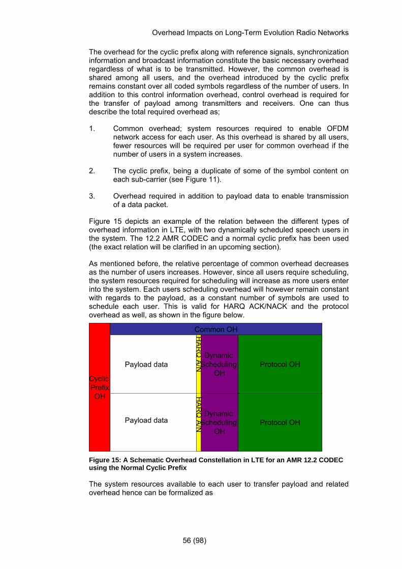
Overhead Impacts on Long-Term Evolution Radio Networks
56 (98)
The overhead for the cyclic prefix along with reference signals, synchronization information and broadcast information constitute the basic necessary overhead regardless of what is to be transmitted. However, the common overhead is shared among all users, and the overhead introduced by the cyclic prefix remains constant over all coded symbols regardless of the number of users. In addition to this control information overhead, control overhead is required for the transfer of payload among transmitters and receivers. One can thus describe the total required overhead as;
1. Common overhead; system resources required to enable OFDM network access for each user. As this overhead is shared by all users, fewer resources will be required per user for common overhead if the number of users in a system increases.
2. The cyclic prefix, being a duplicate of some of the symbol content on each sub-carrier (see Figure 11).
3. Overhead required in addition to payload data to enable transmission of a data packet.
Figure 15 depicts an example of the relation between the different types of overhead information in LTE, with two dynamically scheduled speech users in the system. The 12.2 AMR CODEC and a normal cyclic prefix has been used (the exact relation will be clarified in an upcoming section).
As mentioned before, the relative percentage of common overhead decreases as the number of users increases. However, since all users require scheduling, the system resources required for scheduling will increase as more users enter into the system. Each users scheduling overhead will however remain constant with regards to the payload, as a constant number of symbols are used to schedule each user. This is valid for HARQ ACK/NACK and the protocol overhead as well, as shown in the figure below.
Dynamic Scheduling
OH
Cyclic PrefixOH
Common OH
Payload data
Payload data Protocol OH
HA
RQ
A/N
HAR
Q A/N
Dynamic Scheduling
OHProtocol OH
Figure 15: A Schematic Overhead Constellation in LTE for an AMR 12.2 CODEC using the Normal Cyclic Prefix
The system resources available to each user to transfer payload and related overhead hence can be formalized as
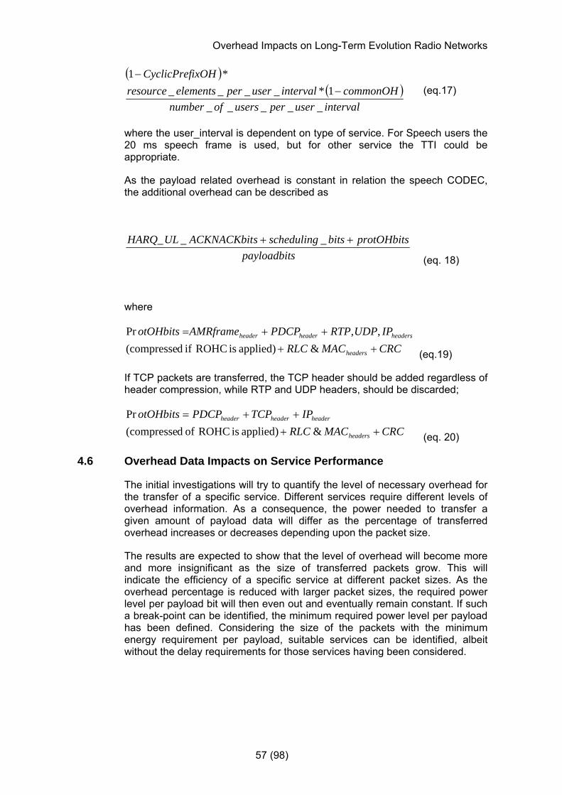
Overhead Impacts on Long-Term Evolution Radio Networks
57 (98)
( )( )intervaluserperusersofnumber
commonOHintervaluserperelementsresourceixOHCyclicPref
_____1*____
*1−
− (eq.17)
where the user_interval is dependent on type of service. For Speech users the 20 ms speech frame is used, but for other service the TTI could be appropriate.
As the payload related overhead is constant in relation the speech CODEC, the additional overhead can be described as
spayloadbitprotOHbitsbitsschedulingsACKNACKbitULHARQ ++ ___
(eq. 18)
where
CRCMACRLCIPUDPRTPPDCPAMRframeotOHbits
headers
headersheaderheader
++++=
&applied) is ROHC if d(compresse ,,Pr
(eq.19)
If TCP packets are transferred, the TCP header should be added regardless of header compression, while RTP and UDP headers, should be discarded;
CRCMACRLCIPTCPPDCPotOHbits
headers
headerheaderheader
++++=
&applied) is ROHC of d(compressePr
(eq. 20)
4.6 Overhead Data Impacts on Service Performance
The initial investigations will try to quantify the level of necessary overhead for the transfer of a specific service. Different services require different levels of overhead information. As a consequence, the power needed to transfer a given amount of payload data will differ as the percentage of transferred overhead increases or decreases depending upon the packet size.
The results are expected to show that the level of overhead will become more and more insignificant as the size of transferred packets grow. This will indicate the efficiency of a specific service at different packet sizes. As the overhead percentage is reduced with larger packet sizes, the required power level per payload bit will then even out and eventually remain constant. If such a break-point can be identified, the minimum required power level per payload has been defined. Considering the size of the packets with the minimum energy requirement per payload, suitable services can be identified, albeit without the delay requirements for those services having been considered.

Overhead Impacts on Long-Term Evolution Radio Networks
58 (98)
Depending on the size of packets, specific types of overhead information could impact the need for energy more than others. By separating the overhead content, individual overhead contributors are singled out and quantified relative to the payload. Results will hopefully suggest potential improvements on when and where to exclude or apply more compressed overhead information, and when to adjust the service expectations to required levels of overhead.
The transmission of overhead information can potentially degrade the service performance when small data packets are transferred. To investigate this, the transmitted downlink power needs to be quantified, where the major contributors of overhead data are pin-pointed and discussed specifically. The coding strategy used for different types of data packets also needs to be clarified.
4.7 Energy Transmission Considering DTX
In order to transmit the SID frames over the speech channel during DTX periods, in total 51 bits14 are transmitted every 160 ms, requiring 42 resource elements, or 42/672000 (0.00625 %) of the available resource elements per user with 16 QAM and a code rate of 1/3, during DTX periods.
The voice activity factor stipulates how many speech frames are transmitting actual speech). Remaining speech frames are transmitting SID frames and related overhead. The total number of speech payload symbols needed per user can thus be described as a weighted average of DTX and speech periods:
( )⎟⎟⎟⎟
⎠
⎞
⎜⎜⎜⎜
⎝
⎛
−+⎟⎟⎠
⎞⎜⎜⎝
⎛81 AMRframe
SID
AMRframe
AMR ElementsSymbols
VAFElements
SymbolsVAF (eq. 21)
where AMRSymbols and SIDSymbols represent symbols used for speech payload (A/B/(C) bits), and symbols required for SIDframes, including the AMR CODEC speech frame overhead (see section 4.2).
4.8 Environment Details
Resource elements not used to transfer control or payload information are assumed empty in accordance with [35], enabling a reduction in power whenever resource elements do not need to transfer information.
A resource block is defined as resource elements during 1 TTI spanning over 12 frequencies (as in [35]). One user is mapped to one resource block unless otherwise stated.
Normal cyclic prefix length is assumed unless otherwise stated, resulting in a structure per resource element of 7 consecutive symbols per slot and frequency, and 14 consecutive symbols per a 1 ms TTI.
14 39 bits payload bits + 10 bits + 7 padding bits assumed as AMR frame overhead during DTX [43], 0.
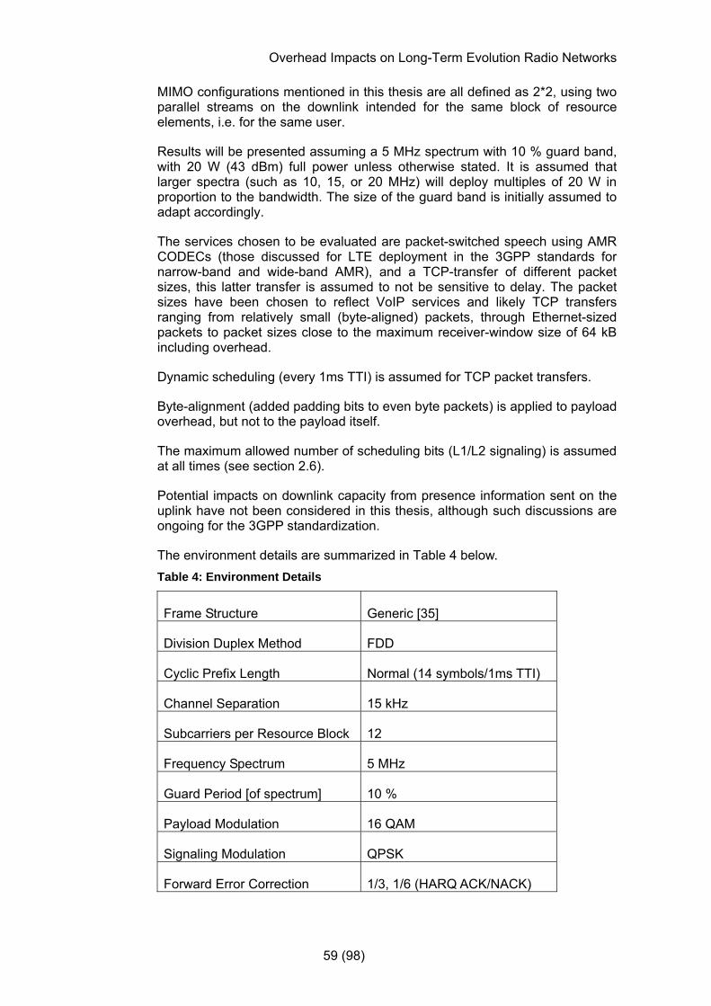
Overhead Impacts on Long-Term Evolution Radio Networks
59 (98)
MIMO configurations mentioned in this thesis are all defined as 2*2, using two parallel streams on the downlink intended for the same block of resource elements, i.e. for the same user.
Results will be presented assuming a 5 MHz spectrum with 10 % guard band, with 20 W (43 dBm) full power unless otherwise stated. It is assumed that larger spectra (such as 10, 15, or 20 MHz) will deploy multiples of 20 W in proportion to the bandwidth. The size of the guard band is initially assumed to adapt accordingly.
The services chosen to be evaluated are packet-switched speech using AMR CODECs (those discussed for LTE deployment in the 3GPP standards for narrow-band and wide-band AMR), and a TCP-transfer of different packet sizes, this latter transfer is assumed to not be sensitive to delay. The packet sizes have been chosen to reflect VoIP services and likely TCP transfers ranging from relatively small (byte-aligned) packets, through Ethernet-sized packets to packet sizes close to the maximum receiver-window size of 64 kB including overhead.
Dynamic scheduling (every 1ms TTI) is assumed for TCP packet transfers.
Byte-alignment (added padding bits to even byte packets) is applied to payload overhead, but not to the payload itself.
The maximum allowed number of scheduling bits (L1/L2 signaling) is assumed at all times (see section 2.6).
Potential impacts on downlink capacity from presence information sent on the uplink have not been considered in this thesis, although such discussions are ongoing for the 3GPP standardization.
The environment details are summarized in Table 4 below. Table 4: Environment Details
Frame Structure Generic [35]
Division Duplex Method FDD
Cyclic Prefix Length Normal (14 symbols/1ms TTI)
Channel Separation 15 kHz
Subcarriers per Resource Block 12
Frequency Spectrum 5 MHz
Guard Period [of spectrum] 10 %
Payload Modulation 16 QAM
Signaling Modulation QPSK
Forward Error Correction 1/3, 1/6 (HARQ ACK/NACK)
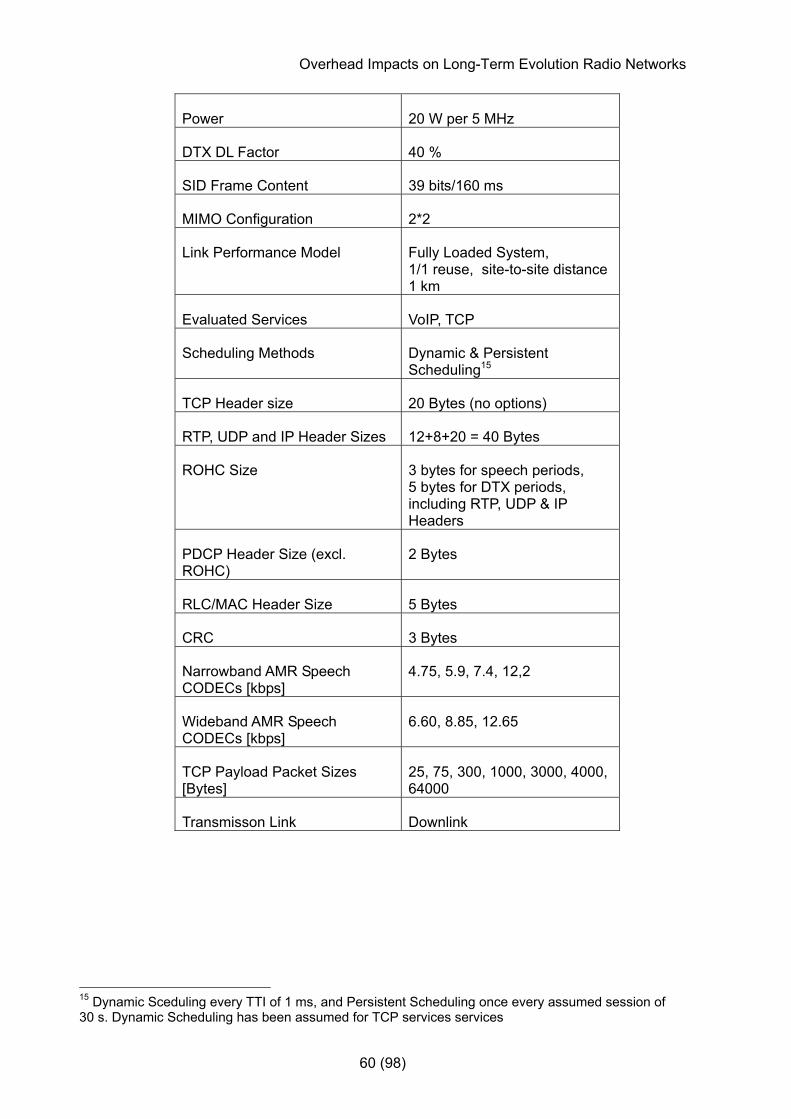
Overhead Impacts on Long-Term Evolution Radio Networks
60 (98)
Power 20 W per 5 MHz
DTX DL Factor 40 %
SID Frame Content 39 bits/160 ms
MIMO Configuration 2*2
Link Performance Model Fully Loaded System, 1/1 reuse, site-to-site distance 1 km
Evaluated Services VoIP, TCP
Scheduling Methods Dynamic & Persistent Scheduling15
TCP Header size 20 Bytes (no options)
RTP, UDP and IP Header Sizes 12+8+20 = 40 Bytes
ROHC Size 3 bytes for speech periods, 5 bytes for DTX periods, including RTP, UDP & IP Headers
PDCP Header Size (excl. ROHC)
2 Bytes
RLC/MAC Header Size 5 Bytes
CRC 3 Bytes
Narrowband AMR Speech CODECs [kbps]
4.75, 5.9, 7.4, 12,2
Wideband AMR Speech CODECs [kbps]
6.60, 8.85, 12.65
TCP Payload Packet Sizes [Bytes]
25, 75, 300, 1000, 3000, 4000, 64000
Transmisson Link Downlink
15 Dynamic Sceduling every TTI of 1 ms, and Persistent Scheduling once every assumed session of 30 s. Dynamic Scheduling has been assumed for TCP services services

Overhead Impacts on Long-Term Evolution Radio Networks
61 (98)
5 Results
5.1 Common Control Information Overhead
All users of LTE are subject to a specific percentage of common control information; pilot symbols or reference signals, synchronization signals, and broadcast information. This control information is common for all users, regardless of the number of users in the system.
The discussions in section 2.7, explain why a number of duplicated symbols - the cyclic prefix – should be added to the signal to inhibit ICI and ISI, and maintain orthogonality by accommodating changes in multipath delay. When the cyclic prefix is extended, the control information overhead will increase. However, the number of symbols transferred per resource block is reduced (as described in section 2.14). As a consequence, larger overhead is added onto each symbol (see Figure 16), and more system resources are required for transmitting cyclic prefix information that is filtered out by the receiver. This will likely reduce the capacity for simultaneous users accordingly; hence, the energy requirement per bit of payload is of interest.
.
Normal Prefix length Extended Prefix Length0
2
4
6
8
10
12
14
16
18
20
Sym
bol P
erce
ntag
e us
ed b
y th
e C
yclic
Pre
fix [%
]
Figure 16: Cyclic Prefix Overhead per Symbol
Figure 17 describes the percentage overhead of system resources in terms of signals that are common to all users (reference signals, synchronization signals, and broadcast channel information). The bars display the overhead percentage using the normal and extended cyclic prefix, for a single-antenna configuration and for a 2*2 MIMO configuration.
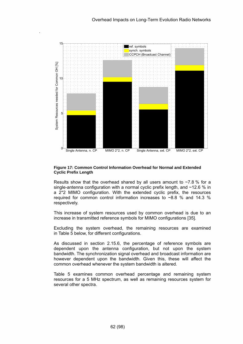
Overhead Impacts on Long-Term Evolution Radio Networks
62 (98)
.
Single Antenna, n. CP MIMO 2*2, n. CP Single Antenna, ext. CP MIMO 2*2, ext. CP0
5
10
15
Syst
em R
esou
rces
nee
ded
for C
omm
on O
H [%
]
ref. symbolssynch. symbolsCCPCH (Broadcast Channel)
Figure 17: Common Control Information Overhead for Normal and Extended Cyclic Prefix Length
Results show that the overhead shared by all users amount to ~7.8 % for a single-antenna configuration with a normal cyclic prefix length, and ~12.6 % in a 2*2 MIMO configuration. With the extended cyclic prefix, the resources required for common control information increases to ~8.8 % and 14.3 % respectively.
This increase of system resources used by common overhead is due to an increase in transmitted reference symbols for MIMO configurations [35].
Excluding the system overhead, the remaining resources are examined in Table 5 below, for different configurations.
As discussed in section 2.15.6, the percentage of reference symbols are dependent upon the antenna configuration, but not upon the system bandwidth. The synchronization signal overhead and broadcast information are however dependent upon the bandwidth. Given this, these will affect the common overhead whenever the system bandwidth is altered.
Table 5 examines common overhead percentage and remaining system resources for a 5 MHz spectrum, as well as remaining resources system for several other spectra.
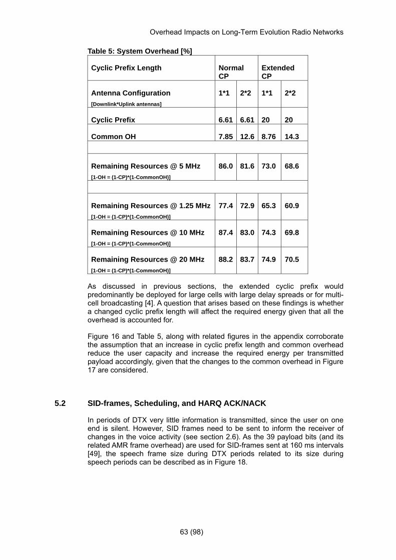
Overhead Impacts on Long-Term Evolution Radio Networks
63 (98)
Table 5: System Overhead [%]
Cyclic Prefix Length Normal CP
Extended CP
Antenna Configuration [Downlink*Uplink antennas]
1*1 2*2 1*1 2*2
Cyclic Prefix 6.61 6.61 20 20
Common OH 7.85 12.6 8.76 14.3
Remaining Resources @ 5 MHz [1-OH = (1-CP)*(1-CommonOH)]
86.0 81.6 73.0 68.6
Remaining Resources @ 1.25 MHz [1-OH = (1-CP)*(1-CommonOH)]
77.4 72.9 65.3 60.9
Remaining Resources @ 10 MHz [1-OH = (1-CP)*(1-CommonOH)]
87.4 83.0 74.3 69.8
Remaining Resources @ 20 MHz [1-OH = (1-CP)*(1-CommonOH)]
88.2 83.7 74.9 70.5
As discussed in previous sections, the extended cyclic prefix would predominantly be deployed for large cells with large delay spreads or for multi-cell broadcasting [4]. A question that arises based on these findings is whether a changed cyclic prefix length will affect the required energy given that all the overhead is accounted for.
Figure 16 and Table 5, along with related figures in the appendix corroborate the assumption that an increase in cyclic prefix length and common overhead reduce the user capacity and increase the required energy per transmitted payload accordingly, given that the changes to the common overhead in Figure 17 are considered.
5.2 SID-frames, Scheduling, and HARQ ACK/NACK
In periods of DTX very little information is transmitted, since the user on one end is silent. However, SID frames need to be sent to inform the receiver of changes in the voice activity (see section 2.6). As the 39 payload bits (and its related AMR frame overhead) are used for SID-frames sent at 160 ms intervals [49], the speech frame size during DTX periods related to its size during speech periods can be described as in Figure 18.
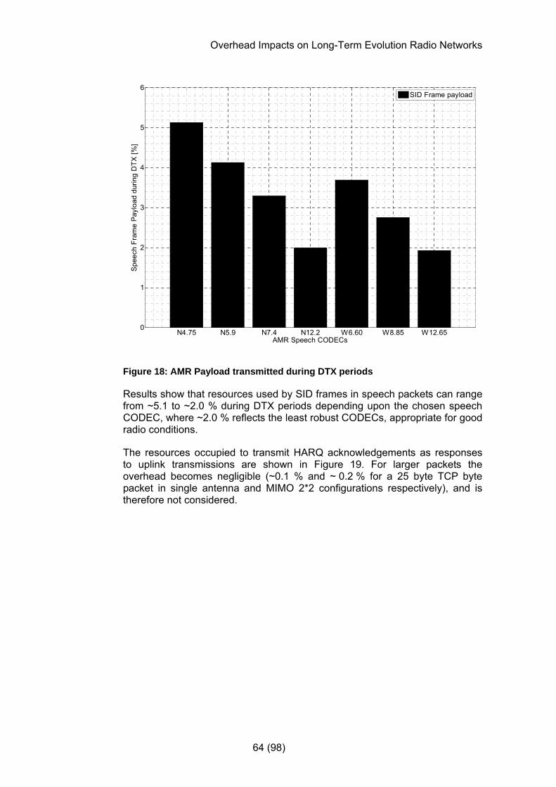
Overhead Impacts on Long-Term Evolution Radio Networks
64 (98)
N4.75 N5.9 N7.4 N12.2 W6.60 W8.85 W12.650
1
2
3
4
5
6
Spe
ech
Fram
e Pa
yloa
d du
ring
DTX
[%]
AMR Speech CODECs
SID Frame payload
Figure 18: AMR Payload transmitted during DTX periods
Results show that resources used by SID frames in speech packets can range from ~5.1 to ~2.0 % during DTX periods depending upon the chosen speech CODEC, where ~2.0 % reflects the least robust CODECs, appropriate for good radio conditions.
The resources occupied to transmit HARQ acknowledgements as responses to uplink transmissions are shown in Figure 19. For larger packets the overhead becomes negligible (~0.1 % and ~ 0.2 % for a 25 byte TCP byte packet in single antenna and MIMO 2*2 configurations respectively), and is therefore not considered.
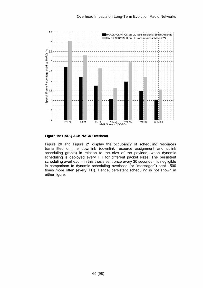
Overhead Impacts on Long-Term Evolution Radio Networks
65 (98)
N4.75 N5.9 N7.4 N12.2 W6.60 W8.85 W12.650
0.5
1
1.5
2
2.5
3
3.5
4
4.5
Spe
ech
Fram
e P
erce
ntag
e us
ed b
y H
AR
Q [%
]
AMR Speech CODECs
HARQ ACK/NACK on UL transmissions: Single AntennaHARQ ACK/NACK on UL transmissions: MIMO 2*2
Figure 19: HARQ ACK/NACK Overhead
Figure 20 and Figure 21 display the occupancy of scheduling resources transmitted on the downlink (downlink resource assignment and uplink scheduling grants) in relation to the size of the payload, when dynamic scheduling is deployed every TTI for different packet sizes. The persistent scheduling overhead – in this thesis sent once every 30 seconds – is negligible in comparison to dynamic scheduling overhead (or “messages”) sent 1500 times more often (every TTI). Hence; persistent scheduling is not shown in either figure.
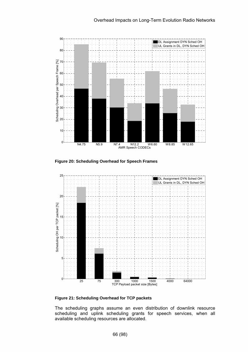
Overhead Impacts on Long-Term Evolution Radio Networks
66 (98)
N4.75 N5.9 N7.4 N12.2 W6.60 W8.85 W12.650
10
20
30
40
50
60
70
80
90
Sche
dulin
g O
verh
ead
per S
peec
h Fr
ame
[%]
AMR Speech CODECs
DL Assignment DYN Sched OHUL Grants in DL, DYN Sched OH
Figure 20: Scheduling Overhead for Speech Frames
25 75 300 1000 1500 4000 640000
5
10
15
20
25
Sche
dulin
g O
H p
er T
CP
pack
et [%
]
TCP Payload packet size [Bytes]
DL Assignment DYN Sched OHUL Grants in DL, DYN Sched OH
Figure 21: Scheduling Overhead for TCP packets
The scheduling graphs assume an even distribution of downlink resource scheduling and uplink scheduling grants for speech services, when all available scheduling resources are allocated.

Overhead Impacts on Long-Term Evolution Radio Networks
67 (98)
As Figure 21 reflects, the uplink/downlink transfer ratio is changed for TCP transfers in comparison to Figure 20. 80 % of the scheduling traffic is now assumed for downlink resource assignments and 20 % for the uplink scheduling grants. Even though either downlink or uplink scheduling could be predominant depending on the service, the total scheduling overhead would however remain the same for a given packet size, unless the scheduling strategy itself is changed as all available scheduling resources are assumed allocated.
With regards to scheduling overhead discussed above it should be noted that dynamic scheduling can limit the total number of simultaneous users in an LTE system, since the PDCCH channel only can cater for a limited number of users per TTI (as discussed in section 4.3). However, if scheduling information can be sent at longer intervals, the PDCCH capacity will allow more users, given that the services provided can tolerate the delays potentially introduced when resources are scheduled less frequently.
5.3 Protocol Overhead
Based on the assumptions for protocol overhead discussed in sections 2.12 and 4.1, it would be interesting to see whether any of these protocol headers occupy a larger part of a transmitted packet than others when packet sizes change. The percentage of protocol header overhead will decrease as the packet size increases, but it remains to be determined how this will affect the energy that needs to be transmitted to convey a given amount of payload data.
Figure 22 displays the level of protocol headers in an AMR packet, relative to the size of the payload, while Figure 23 shows protocol overhead relative to the size of the payload of a TCP packet. The different header types are summarized in the two lowest bars for all packet sizes, with and without the use of ROHC compression.

Overhead Impacts on Long-Term Evolution Radio Networks
68 (98)
0 50 100 150 200 250 300 350 400 450
N4.75
N5.9
N7.4
N12.2
W6.60
W8.85
W12.65
Speech Frame Payload Overhead Required by Protocol Headers [%]
AM
R S
peec
h C
OD
EC
s
Protocol OH in total without ROHCProtocol OH in total with ROHCL1 CRCRLC & MAC HeadersROHC [RTP/UDP/IP]PDCP HeaderRTP/UDP/IP Headers [no ROHC]AMR Frame Header
Figure 22: Protocol overhead for AMR packets
From Figure 22 it is apparent that the payload overhead is quite large for a small packet service such as speech, ranging from ~139 % of the payload size down to ~51.3 % with dynamic scheduling and header compression (ROHC), depending on the speech CODEC. Without header compression, the overhead will range from ~445 % down to ~168 % of the payload for speech packets.

Overhead Impacts on Long-Term Evolution Radio Networks
69 (98)
0 20 40 60 80 100 120 140 160 180 200
25
75
300
1000
1500
4000
64000TC
P P
aylo
ad p
acke
t siz
e [B
ytes
]
Packet Payload Overhead Required by Protocol Headers [%]
Protocol OH in total without ROHCProtocol OH in total with ROHCL1 CRCRLC & MAC HeadersROHC [IP]PDCP HeaderIP Header [no ROHC]TCP Header
Figure 23: Protocol overhead for TCP packets
The graphs suggest that header compression can drastically reduce the relative protocol overhead, at least for a packet size equal to or smaller than ~1000 bytes.
An interesting observation in Figure 22 and Figure 23 (recalling previously shown overhead figures) is that protocol header overhead seems to constitute a large part of the overhead, regardless of the packet size. This is discussed further in section 0.
5.4 Total Overhead
When summarizing the previous findings the overhead percentage can be described as shown in Figure 14 where the total overhead consists of system resources shared by all users, and payload overhead that is additional to the payload of each user.
Figure 24 shows the required system overhead for up to 260 users – increasing with the number of users when dynamic scheduling and ROHC is applied. The maximum of 260 users have been specifically chosen to reflect the presumed scheduling capacity limits of dynamic scheduling of speech users in a single antenna configuration (given a certain message size and MSC), as previously discussed.

Overhead Impacts on Long-Term Evolution Radio Networks
70 (98)
1-260 users, Single Antenna 1-260 users, MIMO 2*20
5
10
15
20
25
30
35
Com
mon
OH
, (D
yn.)
Sch
edul
ing,
HA
RQ
AC
K/N
AC
K &
Pro
toco
l Hea
ders
[%]
Scheduled Users
Using Persistent Scheduling once every 30 s
Figure 24: System Overhead
Figure 25, Figure 26, and Figure 27 depict the total summarized required payload overhead, depending upon the scheduling algorithm and packet size.
0 100 200 300 400 500 600
N4.75
N5.9
N7.4
N12.2
W6.60
W8.85
W12.65
AM
R S
peec
h C
OD
EC
s
Total AMR Payload Overhead [HARQ ACK/NACK, DYN Sched, Protocol OH] [%]
1*1 ROHC2*2 ROHC1*1 no ROHC2*2 no ROHC
Figure 25: Summarized Payload Overhead per AMR Speech Frame (Dynamic Scheduling)
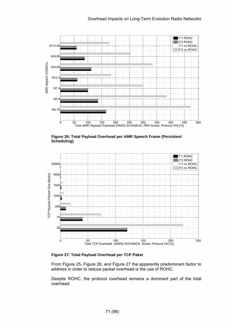
Overhead Impacts on Long-Term Evolution Radio Networks
71 (98)
0 50 100 150 200 250 300 350 400 450 500
N4.75
N5.9
N7.4
N12.2
W6.60
W8.85
W12.65A
MR
Spe
ech
CO
DE
Cs
Total AMR Payload Overhead [HARQ ACK/NACK, PER Sched, Protocol OH] [%]
1*1 ROHC2*2 ROHC1*1 no ROHC2*2 no ROHC
Figure 26: Total Payload Overhead per AMR Speech Frame (Persistent Scheduling)
0 50 100 150 200 250
25
75
300
1000
1500
4000
64000
TCP
Pay
load
Pac
ket S
ize
[Byt
es]
Total TCP Overhead (HARQ ACK/NACK, Sched, Protocol OH [%]
1*1 ROHC2*2 ROHC1*1 no ROHC2*2 no ROHC
Figure 27: Total Payload Overhead per TCP Paket
From Figure 25, Figure 26, and Figure 27 the apparently predominant factor to address in order to reduce packet overhead is the use of ROHC.
Despite ROHC, the protocol overhead remains a dominant part of the total overhead.

Overhead Impacts on Long-Term Evolution Radio Networks
72 (98)
It should also be noted that the percentage of total overhead continuously decrease, and the impact on required energy will diminish as the packet size increases beyond 1kB.
As previously discussed, the use of different scheduling algorithms can lower the required payload overhead. However, in order to quantify the impact of changing algorithms, the predominant overhead contributors have to be examined. Figure 28 shows how much of the total overhead that is used for scheduling and protocol headers for two common AMR speech CODECs. It now remains to investigate how much the total overhead is reduced if the scheduling overhead from Figure 28 is reduced drastically.
NAMR 7.4 NAMR 12.20
50
100
150 Single Antenna, With ROHC
Pay
load
OH
[%]
AMR Speech CODECs
Dyn Scheduling OHProtocol Headers [AMR Frame Header, PDCP, ROHC [RTP, UDP, IP], RLC, MAC, CRC]
Figure 28: Predominant Payload Overhead for AMR CODECs
Figure 29 describes the reduction in total overhead that could be obtained if using persistent scheduling every 30 seconds instead of dynamic scheduling every 1ms TTI. A reduction of ~35 % and ~16 % in overhead is achieved with persistent instead of dynamic scheduling with or without ROHC, for two typical AMR speech CODECs.
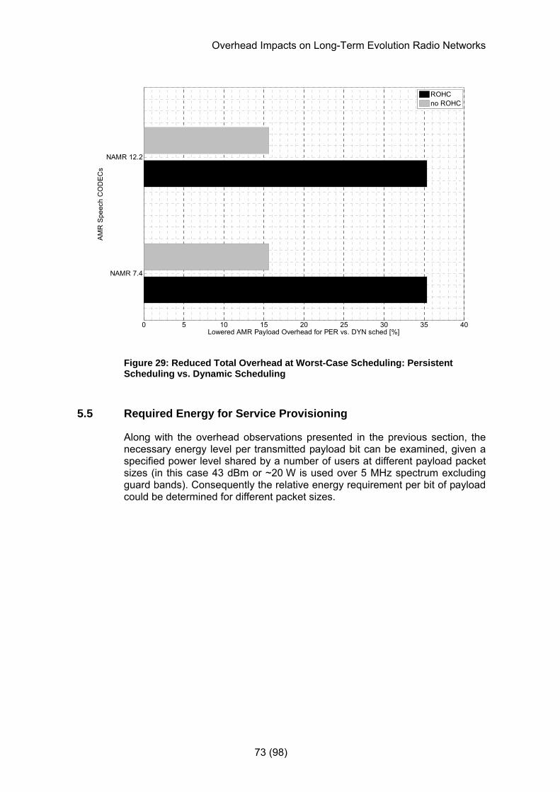
Overhead Impacts on Long-Term Evolution Radio Networks
73 (98)
0 5 10 15 20 25 30 35 40
NAMR 7.4
NAMR 12.2
AMR
Spe
ech
CO
DEC
s
Lowered AMR Payload Overhead for PER vs. DYN sched [%]
ROHCno ROHC
Figure 29: Reduced Total Overhead at Worst-Case Scheduling: Persistent Scheduling vs. Dynamic Scheduling
5.5 Required Energy for Service Provisioning
Along with the overhead observations presented in the previous section, the necessary energy level per transmitted payload bit can be examined, given a specified power level shared by a number of users at different payload packet sizes (in this case 43 dBm or ~20 W is used over 5 MHz spectrum excluding guard bands). Consequently the relative energy requirement per bit of payload could be determined for different packet sizes.
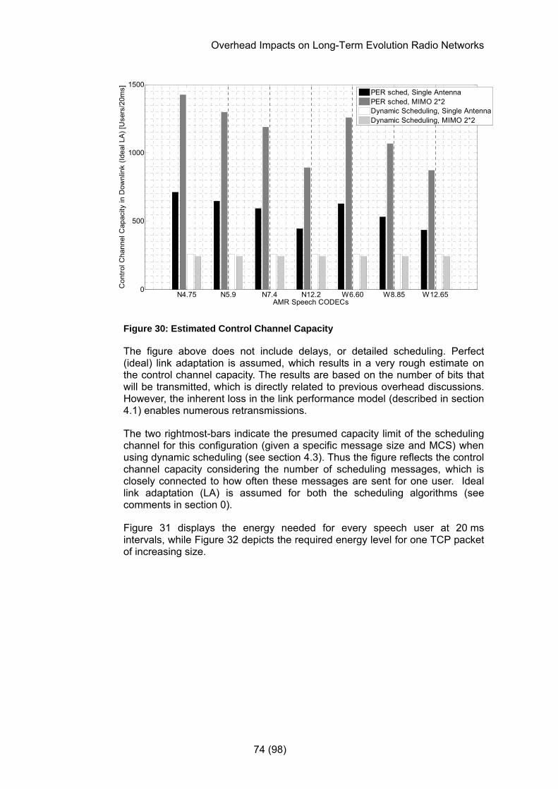
Overhead Impacts on Long-Term Evolution Radio Networks
74 (98)
N4.75 N5.9 N7.4 N12.2 W6.60 W8.85 W12.650
500
1000
1500
AMR Speech CODECs
Con
trol C
hann
el C
apac
ity in
Dow
nlin
k (Id
eal L
A) [
Use
rs/2
0ms]
PER sched, Single AntennaPER sched, MIMO 2*2Dynamic Scheduling, Single AntennaDynamic Scheduling, MIMO 2*2
Figure 30: Estimated Control Channel Capacity
The figure above does not include delays, or detailed scheduling. Perfect (ideal) link adaptation is assumed, which results in a very rough estimate on the control channel capacity. The results are based on the number of bits that will be transmitted, which is directly related to previous overhead discussions. However, the inherent loss in the link performance model (described in section 4.1) enables numerous retransmissions.
The two rightmost-bars indicate the presumed capacity limit of the scheduling channel for this configuration (given a specific message size and MCS) when using dynamic scheduling (see section 4.3). Thus the figure reflects the control channel capacity considering the number of scheduling messages, which is closely connected to how often these messages are sent for one user. Ideal link adaptation (LA) is assumed for both the scheduling algorithms (see comments in section 0).
Figure 31 displays the energy needed for every speech user at 20 ms intervals, while Figure 32 depicts the required energy level for one TCP packet of increasing size.
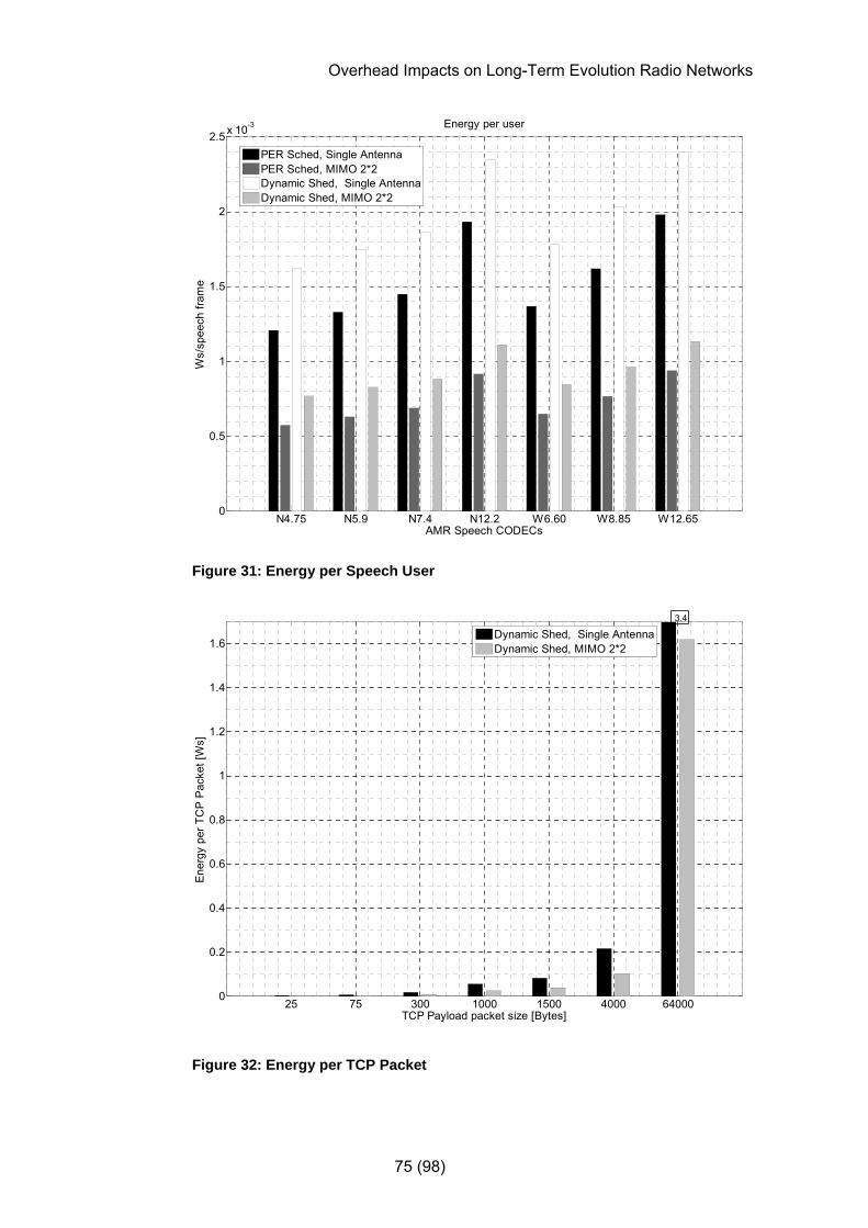
Overhead Impacts on Long-Term Evolution Radio Networks
75 (98)
N4.75 N5.9 N7.4 N12.2 W6.60 W8.85 W12.650
0.5
1
1.5
2
2.5 x 10⁻³ Energy per user
Ws/
spee
ch fr
ame
AMR Speech CODECs
PER Sched, Single AntennaPER Sched, MIMO 2*2Dynamic Shed, Single AntennaDynamic Shed, MIMO 2*2
Figure 31: Energy per Speech User
25 75 300 1000 1500 4000 640000
0.2
0.4
0.6
0.8
1
1.2
1.4
1.6
TCP Payload packet size [Bytes]
Ener
gy p
er T
CP
Pac
ket [
Ws]
Dynamic Shed, Single AntennaDynamic Shed, MIMO 2*2
3.4
Figure 32: Energy per TCP Packet

Overhead Impacts on Long-Term Evolution Radio Networks
76 (98)
If the energy needed to transfer a TCP packet is distributed over the payload for that packet, a relative measure of the required level of energy to provide a specific packet service is obtained. Figure 33 presents this, while Figure 34 reflects the inverse by depicting the amount of payload bits transferred per energy level.
25 75 300 1000 1500 4000 640000
2
4
6
8
10
12
14
16
Ene
rgy
per p
aylo
ad [W
s/M
bit]
TCP Payload packet size [Bytes]
Single AntennaMIMO 2*2
Figure 33: Energy per TCP Payload

Overhead Impacts on Long-Term Evolution Radio Networks
77 (98)
25 75 300 1000 1500 4000 640000
0.05
0.1
0.15
0.2
0.25
0.3
0.35
Payl
oad
per E
nerg
y Q
uant
a [M
bit/W
s]
TCP Payload packet size [Bytes]
Single AntennaMIMO 2*2
Figure 34: TCP Payload per Ws
5.6 Boosted Reference Signal Power
As discussed in section 2.15.6, increasing the power on reference signals will increase required system overhead. Figure 35 shows the absolute levels of required system control overhead when the reference signal power is increased in steps of one dB.
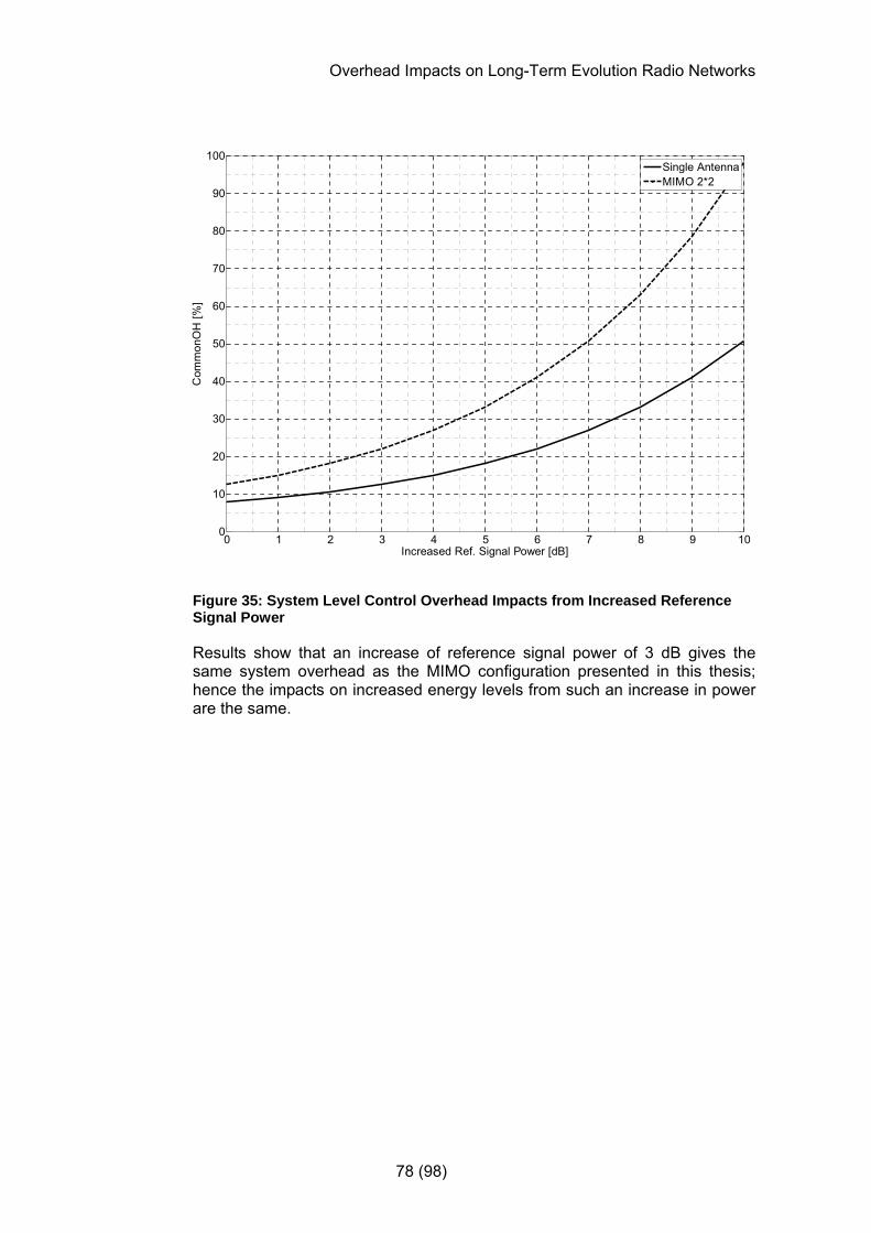
Overhead Impacts on Long-Term Evolution Radio Networks
78 (98)
0 1 2 3 4 5 6 7 8 9 100
10
20
30
40
50
60
70
80
90
100
Increased Ref. Signal Power [dB]
Com
mon
OH
[%]
Single AntennaMIMO 2*2
Figure 35: System Level Control Overhead Impacts from Increased Reference Signal Power
Results show that an increase of reference signal power of 3 dB gives the same system overhead as the MIMO configuration presented in this thesis; hence the impacts on increased energy levels from such an increase in power are the same.

Overhead Impacts on Long-Term Evolution Radio Networks
79 (98)
6 Discussion
For smaller packets, such as packet-oriented speech packets, the protocol overhead will – depending on the CODEC – require roughly 1.4 up to ~4.5 times the resources of the payload (see Figure 25 and Figure 26). Evidently (as expected), the smaller the packet, the more useful IP header compression (ROHC) seems, in terms of added overhead relative to the size of the payload. The high percentage of overhead for smaller packets (relative to the payload size) suggests that a number of users should be multiplexed in order to make the most effective use of the available spectrum.
For packets with payload sizes beyond ~1kB, the required increase in receiver processor complexity and likely increase in retransmissions due to an increase in faulty decoding, might not justify the use of ROHC, unless the system strategy is to simplify the overall design by deploying only one mapping algorithm, regardless of the service or packet size.
Despite ROHC header compression, protocol overhead seems to be a major contributor to payload overhead. However in most cases the transferred packets will be a maximum transmission unit (MTU) in size. Hence the protocol overhead will be very small. For file transfers, small packets – with a larger percentage overhead – will likely occur about once per file, while for AMR or other packets with a minimal size header, the overhead is more extensive.
While non-multiplexed AMR packets would need a change in scheduling when there is a silence period to active period transition (and the same for the reverse), multiplexed AMR packets would only need a change in scheduling when there is a substantial change in resource requirements. Thus an efficient multiplexing algorithm would not require changed scheduling very often, as the scheduling would be based on the statistics of the multiplexed AMR stream rather than an individual AMR stream.
Comparing two extreme cases of scheduling – dynamic scheduling every TTI, and persistent scheduling once every average session of 30 seconds – indicate a reduction in total overhead of either ~16 % or ~35 %, where the latter applies when ROHC is used. What it means capacity-wise to schedule resources more seldom depends on details of, e.g., the chosen algorithm and environment. As previously mentioned, this is outside the scope of this thesis.
If considering the dynamic and persistent scheduling investigated in this thesis as two extreme cases of scheduling algorithms, while assuming that the gain in capacity is proportional to the gain in control channel capacity, one can estimate the capacity gain to ~1.7-2.7 times that of dynamic scheduling in a single antenna configuration, and ~3.6-5.9 times using MIMO 2*2, depending upon the chosen CODEC (see Figure 30). Such a comparison is based on ideal link adaptation and that the system capacity with dynamic scheduling is limited by the capacity of the scheduling channel. However, even the most optimistic persistent scheduling would have to cater for users on the cell edges, resulting in more overhead for users on a better channel. Thus, the results with persistent scheduling are far too optimistic, depending upon the link adaptation and the modulation and coding scheme.

Overhead Impacts on Long-Term Evolution Radio Networks
80 (98)
The power required for a transfer decreases as the overhead is reduced. However, the power per transferred payload content evens out as the packet sizes grow beyond ~1kB. This suggests that services that require for instance Ethernet transfers (~1.5 kB packets) up to the maximum receiver window size (~64 kB), will require about the same power per payload bit regardless of the overhead.
Given that packet sizes above ~1kB requires a constant energy per transmitted bit of payload, and the multiplexing of small packets (mentioned earlier in this section), one could speculate on the optimum multiplexing of a number of small packet (AMR speech) users. In order to reach a payload of ~300 byte – where the required energy per bit of payload start to even out – one would need to multiplex about 10 users given the AMR 12.2 codec and the DTX factor assumed in this thesis. However, this assumes that the protocol overhead currently required per user can be shared among several users. If multiplexing several small packets services one would additionally have to accommodate different protocol headers.
Due to increased control information overhead when the extended cyclic prefix is used, more power is needed per transferred bit of payload. The increase in required power per payload bit corresponds to the added control information overhead and the additional system resources required by the extended cyclic prefix.

Overhead Impacts on Long-Term Evolution Radio Networks
81 (98)
7 Conclusions
• The use of TCP/IP header compression (ROHC) is the single most important factor to reduce payload overhead, for packet sizes of ~1kB or smaller. However, the gain of using ROHC for larger packet sizes is negligible (see Figure 27).
• Protocol headers – including the AMR frame header, RLC/MAC headers, and CRC where applicable – remain the largest part of payload overhead regardless of packet size and header compression (ROHC).
o For VoIP over the UDP protocol (with ROHC), RLC/MAC headers constitute the largest part of protocol headers (see Figure 22).
o For TCP/IP applications (without ROHC), TCP/IP headers are predominant for small payloads (see Figure 23).
• Services that require packet sizes beyond ~1 kB will require about the same power per payload bit regardless of the percentage of payload overhead (see Figure 33).
• Comparing two extreme cases of scheduling – dynamic scheduling every 1 ms TTI, and persistent scheduling once per session of 30 seconds – the payload overhead can be reduced by ~35 % whenever ROHC is applicable. Without ROHC, the payload overhead reduction by using persistent scheduling is ~16 % (see Figure 29).
• Considering the dynamic and persistent scheduling investigated in this thesis as two extreme cases of scheduling algorithms, one can conclude that the overhead is reduced drastically with persistent scheduling (see Figure 30). However, the capacity gain will not be equivalent, due to link adaptation and adjustments for users on the cell edges.
Overhead Impacts on Long-Term Evolution Radio Networks
82 (98)
8 Further Studies
Some possible extensions are:
• Additional studies and system simulations to verify the indications found in this thesis, especially the usefulness of MIMO for larger packets, the overhead impacts from higher layer protocols, and the scheduling efficiency impact on transmitted energy.
• Additional antenna solutions; 4x4 MIMO etc.
• Comparison of the emission and signaling investigation results and similar scenarios using GSM EDGE and or WCDMA/HSDPA, as suitable simulation tools are being developed.
• For what type of services are the two CP lengths chosen by GPP for different delay spreads optimal?
Overhead Impacts on Long-Term Evolution Radio Networks
83 (98)
References
[1] Internet resource: The GSM Association website, GSM/3G Fast Facts, Accessed on Sept. 23 2006, from URL: http://www.gsacom.com/news/statistics.php4?PHPSESSID=f7a1867222cb6b0d07260d0a89d079d5
[2] S. He, Equalization Techniques for Co-channel Interference Suppression, Chalmers University of Technology, Department of Signals and Systems, Master Thesis, EX003/2005, 2005
[3] A. Simonsson, M. Almgren, M. Thurfjell, A Power Control and Scheduling Concept for EGPRS, proc. 52nd Vehicular Technology Conference, IEEE, Sept. 2000, pp 2219-2224
[4] J. Heyman, Intercell Interference Management in an OFDM-based Downlink, Linköping University, Department of Electrical Engineering, Master Thesis, EAB-06:028543 Uen, June 2006
[5] J.D. Bakker, Eliminating the OFDM Cyclic Prefix, 13th IEEE International Symposium on Personal Indoor and Mobile Communications, September 2002, pp 2219-2224.
[6] M. Sundberg, Psedo Random Postfix OFDM, Uppsala University, Master Thesis, Oct. 2005
[7] M. Muck et al., A Pseudo Random Postfix OFDM modulator and inherent channel estimation techniques, Globecom 2003.
[8] R. Kusha et al., The Performance of PCC-OFDM in Multipath Fading Channels, Submitted to Australian Communication Theory Workshop, 2004
[9] International telecommunication union (ITU) Press Release ITU/99-22, Nov. 5, 1999
[10] International telecommunication union (ITU) Press Release ITU/99-24, Dec. 10, 1999
[11] Internet resource: International telecommunication union (ITU) website, What is IMT-2000?, Accessed on Sept. 23 2006, from URL: http://www.itu.int/osg/imt-project/docs/What_is_IMT2000-2.pdf
[12] A. Simonsson, Frequency Reuse and Intercell Interference Co-ordination in E-UTRA. proc. 65th Vehicular Technology Conference, IEEE, 22-25 April 2007, pp 3091-3095
[13] K. Haider, Peak to average ratio reduction in Wireless OFDM communication systems, Master Thesis, Blekinge Institute of Technology, Department of Telecommunications and signal processing, Dec. 2005
Overhead Impacts on Long-Term Evolution Radio Networks
84 (98)
[14] Internet Resource: 3GPP TSG-RAN WG1, R1-071956, Ericsson: E-UTRA Performance Checkpoint: Downlink Initial Super 3G downlink performance assessment, Ericsson, Tech. Report EAB-05:033452 Uen, Nov 2005, Revision Accessed on May 12 2007 from URL: http://www.3gpp.org/ftp/tsg_ran/WG1_RL1/TSGR1_AH/LTE_Performance_evaluation_April-07/Docs/R1-071956.zip
[15] Internet Resource: The RF Design website, L. Litwin, M. Pugel, The Principles of OFDM, Jan. 2001, Accessed on Sept. 30 2006 from URL: http://rfdesign.com/mag/radio_principles_ofdm/index.html
[16] 3GPP TSG-RAN WG1, R1-051348, Samsung: Downlink Resource Allocation and Multiplexing, Accessed on May 7 2007 from URL: http://www.3gpp.org/ftp/tsg_ran/WG1_RL1/TSGR1_43/Docs/R1-051348.zip
[17] R. G. Gallager, Information Theory and Reliable Communication, New York, Wiley, 1968
[18] E. Dahlman, et al., The 3G Long-Term Evolution – Radio Interface Concepts and Performance Evaluation, proc. 63rd Vehicular Technology Conference, IEEE, 2006, pp 137-141
[19] H. Ekström et al., Technical Solutions for the 3G Long-term Evolution, IEEE Communications Magazine, March 2006, pp 38-45
[20] Internet resource: 3GPP, Requirements for Evolved UTRA (E-UTRA) and Evolved UTRAN (E-UTRAN), Tech. Report 25.913, version 7.3.0, Accessed on October 13 2006 from URL: http://www.3gpp.org/ftp/Specs/html-info/25913.htm.
[21] M. A. Aceña, Power and Bit Allocation for Multicarrier Modulation in Multi-user Environments, Master Thesis, Chalmers University of Technology, 2005
[22] Ericsson AB, WCDMA Evolved, Ericsson White Paper, 284 23-2958 Uen Rev A, 2004.
[23] L. Ahlin, C. Frank, and J. Zander, Mobil Radiokommunikation, Studentlitteratur, 1995.
[24] B. Sklar, Rayleigh fading channels in mobile digital communications, IEEE Communications Magazine, July 1997, pp. 90 –100
[25] S.B. Weinstein and P. M. Ebert, Data transmission by frequency-division multiplexing using the discrete fourier transform, IEEE Transactions on Communications Technology. Volume: COM-19, No. 5 , October 1971, pp. 628 – 634
Overhead Impacts on Long-Term Evolution Radio Networks
85 (98)
[26] T. Keller and L. Hanzo, “Adaptive multicarrier modulation: a convenient framework for timefrequency processing in wireless communications”, IEEE Proceedings of the IEEE, 2000, Volume: 88 No. 5, May 2000, pp. 611 – 640
[27] Internet resource: 3GPP, Physical Layer Aspects for Evolved Universal Terrestrial Radio Access (E-UTRA), Tech. Report 25.814, version 7.1.0, Accessed on November 1 2006 from URL: http://www.3gpp.org/ftp/Specs/html-info/25814.htm.
[28] Internet resource: 3GPP, Long Term Evolution of the 3GPP radio technology, Accessed on November 1 2006 from URL: http://www.3gpp.org/Highlights/LTE/LTE.htm.
[29] Internet resource: NASA, Goddard Space Flight Centre, Dopppler Shift, Accessed on November 3, 2006 from URL: http://imagine.gsfc.nasa.gov/YBA/M31-velocity/Doppler-shift-2.html
[30] Internet resource: 3GPP, LTE Physical Layer - General Description, 36.201, version 0.1.1, Accessed on November 8 2006 from URL: http://www.3gpp.org/ftp/Specs/html-info/36201.htm
[31] Internet resource: 3GPP, Evolved Universal Terrestrial Radio Access (E-UTRA) and Evolved Universal Terrestrial Radio Access (E-UTRAN); Overall description; Stage 2, 36.300, version 0.3.1, Accessed on January 2 2007 from URL: http://www.3gpp.org/ftp/Specs/html-info/36300.htm
[32] Internet resource: 3GPP, Evolved UTRA Aspects, Specification series 36, Accessed on November 8 2006 from URL: http://www.3gpp.org/ftp/Specs/html-info/36-series.htm
[33] H. Nyquist, Certain Topics in Telegraph Transmission Theory, Transactions of the AIEE (American Institute of Electrical Engineers) vol. 47, Feb. 1928, pp 617-644
[34] C. Shannon, Communication in the presence of noise, Proc. of the IRE, vol. 37, no.1, Jan. 1949, pp. 10–21
[35] Internet resource: 3GPP, Evolved Universal Terrestrial Radio Access (E-UTRA); Physical Channels and Modulation, 36.211, version 0.2.1, Accessed on December 18 2006 from URL: http://www.3gpp.org/ftp/Specs/html-info/36211.htm
[36] M. Ericsson, et. al., Effects of simultaneous circuit and packet voice traffic on total capacity, proc. 63rd Vehicular Technology Conference, IEEE, Spring 2006, pp. 538-542, Accessed on May 3 2007 from URL: http://www.ericsson.com/technology/research_papers/wireless_access/doc/Effects%20of%20simultaneous%20circuit%20and%20packet%20switched.pdf

Overhead Impacts on Long-Term Evolution Radio Networks
86 (98)
[37] S. Wänstedt, et. al., The Effect of F-DPCH on VoIP over HSDPA Capacity, proc. 63rd Vehicular Technology Conference, Spring 2006, pp. 410-414, Accessed on May 3 2007 from URL: http://www.ericsson.com/technology/research_papers/wireless_access/doc/The%20effect%20of%20F-DPCH%20on%20VoIP%20over%20HSDPA.pdf
[38] B. A. Forouzan, TCP/IP Protocol Suite, 3rd Edition, ISBN 0-07-111583-8, McGraw-Hill, 2006
[39] Internet Resource: 3GPP TSG-RAN WG1, R1-061382, Ericsson: E-UTRA Downlink User Throughput and Spectrum Efficiency Evaluation, Accessed on January 9 2007 from URL:http://www.3gpp.org/ftp/tsg_ran/WG1_RL1/TSGR1_45/Docs/R1-061382.zip
[40] Internet resource: 3GPP, Technical Specification Group Radio Access Network, Physical layer aspects of UTRA High Speed Downlink Packet Access, 25.848, version 4.0.0, Accessed on December 20 2006 from URL: http://www.3gpp.org/ftp/Specs/html-info/25848.htm
[41] Internet resource: 3GPP, Technical Specification Group Radio Access Network, Evolved Universal Terrestrial Radio Access (E-UTRA) and Evolved Universal Terrestrial Radio Access Network (E-UTRAN); Radio interface protocol aspects, 25.813, version 7.1.0, Accessed on January 3 2007 from URL: http://www.3gpp.org/ftp/Specs/html-info/25813.htm
[42] Internet resource: 3GPP, Technical Specification Group Radio Access Network, Packet Data Convergence Protocol (PDCP) specification, 25.323, version 7.3.0, Accessed on January 3 2007 from URL: http://www.3gpp.org/ftp/Specs/html-info/25323.htm
[43] Internet resource: 3GPP, Technical Specification Group Services and System Aspects, Adaptive Multi-Rate (AMR) speech CODEC frame structure, 26.101, version 6.0.0, Accessed on January 3 2007 from URL: http://www.3gpp.org/ftp/Specs/html-info/26101.htm
[44] Internet Resource: The Internet Engineering Task Force, Request For Comments, RFC 3095 - RObust Header Compression (ROHC): Framework and four profiles: RTP, UDP, ESP, and uncompressed, Accessed on January 6 2007 from URL:http://www.ietf.org/rfc/rfc3095.txt?number=3095
[45] Internet Resource: 3GPP TSG-RAN WG2, R2-063215, Ericsson: Scheduling Request in E-UTRAN, Accessed on January 9 2007 from URL: http://www.3gpp.org/ftp/tsg_ran/WG2_RL2/TSGR2_56/Documents/R2-063215.zip

Overhead Impacts on Long-Term Evolution Radio Networks
87 (98)
[46] Internet Resource: 3GPP TSG-RAN WG2, R2-062263, Samsung: First quantification on downlink control overhead, Accessed on January 9 2007 from URL: http://www.3gpp.org/ftp/tsg_ran/WG2_RL2/TSGR2_54/Documents/R2-062263.zip
[47] Internet Resource: 3GPP TSG-RAN WG1, R1-063148, Ericsson: L1/L2 Signaling for PICH, Accessed on January 9 2007 from URL: http://www.3gpp.org/ftp/tsg_ran/WG1_RL1/TSGR1_47/Docs/R1-063148.zip
[48] Internet Resource: 3GPP TSG-RAN WG1, R1-063147, Ericsson: Downlink L1/L2 control signaling, Accessed on January 9 2007 from URL: http://www.3gpp.org/ftp/tsg_ran/WG1_RL1/TSGR1_47/Docs/R1-063147.zip
[49] Internet Resource: 3GPP, Technical Specification Group Services and System Aspects, Mandatory speech CODEC speech processing functions, AMR speech CODEC, General description, TS 26.071, version 6.0.0, Accessed on January 18 2007 from URL:
http://www.3gpp.org/ftp/Specs/html-info/26071.htm
[50] P. Björkén et al., Ericsson White Paper, The Evolution of EDGE, Feb. 2007, 285 23-3107, Uen, Rev.A. Accessed on Feb. 15, 2007 from URL: http://www.ericsson.com/technology/whitepapers/3107_The_evolution_of_EDGE_A.pdf
[51] Internet Resoure: 3GPP, Technical Specification Group Radio Access Network, HSPA Evolution (FDD), TR 25.999, Accessed on Feb 19, 2007, from URL: http://www.3gpp.org/ftp/Specs/archive/25_series/25.999/25999-100.zip
[52] Internet resource: C. Berrou et al, Near Shannon-limit Error-Correcting Coding and Decoding: Turbo Codes, IEEE proc. ICC 1993, pp. 1064-1070. Accessed on February 19, 2007 from URL: http://www-elec.enst-bretagne.fr/equipe/berrou/Near%20Shannon%20Limit%20Error.pdf
[53] Internet Resource: Telebit - PEP and the Trailblazer, Accessed on February 27, 2007 from URL: http://en.wikipedia.org/wiki/Telebit
[54] Internet Resource: 3GPP TSG-RAN WG2, R2-070041, Ericsson: Problems of Persistent Scheduling, Accessed on March 2 2007 from URL: http://www.3gpp.org/ftp/tsg_ran/WG2_RL2/TSGR2_56bis/Documents/R2-070041.zip
Overhead Impacts on Long-Term Evolution Radio Networks
88 (98)
[55] Internet Resource: 3GPP TSG-RAN WG2, R2-0662859, Ericsson: Semi-Persistent Scheduling, Accessed on March 2 2007 from URL: http://www.3gpp.org/ftp/tsg_ran/WG2_RL2/TSGR2_55/Documents/R2-062859.zip
[56] Internet Resource: 3GPP TSG-RAN WG2, R2-070055, Ericsson: Scheduling for maximizing VoIP capacity, Accessed on March 2 2007 from URL: http://www.3gpp.org/ftp/tsg_ran/WG2_RL2/TSGR2_56bis/Documents/R2-070055.zip
[57] Internet Resource: 3GPP TSG-RAN WG2, R2-063684, Email agreement: Downlink scheduling: L1/L2 signalling overhead reduction, Accessed on March 2 2007 from URL: http://www.3gpp.org/ftp/tsg_ran/WG2_RL2/TSGR2_56/Documents/R2-063684.zip
[58] Internet Resource: 3GPP TSG-RAN WG2, R2-070396, Ericsson, Nokia, Samsung, RLC PDU format for enhanced L2, Accessed on March 2 2007 from URL: http://www.3gpp.org/ftp/tsg_ran/WG2_RL2/TSGR2_56bis/Documents/R2-070396.zip
[59] J. Sjöberg et al, Real-Time Transport Protocol (RTP) Payload Format and File Storage Format for the Adaptive Multi-Rate (AMR) and Adaptive Multi-Rate Wideband (AMR-WB) Audio Codecs, RFC 3267, Accessed on April 4 2007 from URL: http://www.rfc-archive.org/getrfc.php?rfc=3267
[60] Internet Resource: 3GPP TSG-RAN WG4, R4-0608573, Ericsson: LTE UE Power Class, Accessed on May 3, 2007 from URL: http://www.3gpp.org/ftp/tsg_ran/WG4_Radio/TSGR4_40/Docs/R4-060857.zip
[61] Internet Resource: 3GPP TSG-RAN WG2, Meetings. Accessed on April 20 2007 from URL: http://www.3gpp.org/ftp/tsg_ran/WG2_RL2/
[62] Internet Resource: 3GPP TSG-RAN WG2, R2-063217, Ericsson: Scheduling for maximizing VoIP capacity, Accessed on April 24 2007 from URL: http://www.3gpp.org/ftp/tsg_ran/WG2_RL2/TSGR2_56/Documents/R2-063217.zip
[63] Internet Resource: 3GPP, Technical Specification Group Services and System Aspects, IP Multimedia Subsystem (IMS) Multimedia Telephony, Media handling and interaction, TS 26.114, version 7.0.0, Accessed on April 24 2007 from URL: http://www.3gpp.org/ftp/Specs/html-info/26114.htm
[64] Internet Resource: 3GPP TSG-RAN WG2, R2-070062, Ericsson: RLC-MAC Header Formats, Accessed on April 24 2007 from URL:

Overhead Impacts on Long-Term Evolution Radio Networks
89 (98)
http://www.3gpp.org/ftp/tsg_ran/WG2_RL2/TSGR2_56bis/Documents/R2-070062.zip
[65] Internet Resource: The Internet Engineering Task Force, Request For Comments, RFC 4867 - RTP Payload Format and File Storage Format for the Adaptive Multi-Rate (AMR) and Adaptive Multi-Rate Wideband (AMR-WB) Audio Codecs, Accessed on May 7 2007 from URL: http://www.rfc-editor.org/rfc/rfc4867.txt

Overhead Impacts on Long-Term Evolution Radio Networks
90 (98)
Appendix A: Extended Cyclic Prefix Figures Figure 16 reflects the increase in overhead that an extended CP-length requires. The figures below corroborate the assumption that an increase in energy per payload bit corresponds to the increase in overhead when using the extended cyclic prefix.
0 0.5 1 1.5 2 2.5 30
0.1
0.2
0.3
0.4
0.5
0.6
0.7
0.8
0.9
1
Bits per Symbol
CD
F of
Ful
ly L
oade
d 1/
1 S
yste
m w
ith 1
6 Q
AM
[%]
1*12*2 MIMO
Figure 36: CDFs of the LTE System Model (Extended Cyclic Prefix)
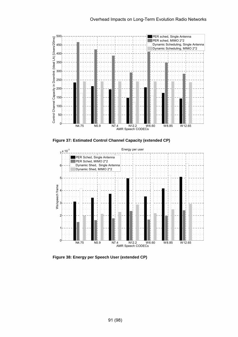
Overhead Impacts on Long-Term Evolution Radio Networks
91 (98)
N4.75 N5.9 N7.4 N12.2 W6.60 W8.85 W12.650
50
100
150
200
250
300
350
400
450
500
AMR Speech CODECs
Con
trol C
hann
el C
apac
ity in
Dow
nlin
k (Id
eal L
A) [
Use
rs/2
0ms]
PER sched, Single AntennaPER sched, MIMO 2*2Dynamic Scheduling, Single AntennaDynamic Scheduling, MIMO 2*2
Figure 37: Estimated Control Channel Capacity (extended CP)
N4.75 N5.9 N7.4 N12.2 W6.60 W8.85 W12.650
1
2
3
4
5
6
7 x 10⁻³ Energy per user
Ws/
spee
ch fr
ame
AMR Speech CODECs
PER Sched, Single AntennaPER Sched, MIMO 2*2Dynamic Shed, Single AntennaDynamic Shed, MIMO 2*2
Figure 38: Energy per Speech User (extended CP)

Overhead Impacts on Long-Term Evolution Radio Networks
92 (98)
25 75 300 1000 1500 4000 640000
0.2
0.4
0.6
0.8
1
1.2
1.4
1.6
TCP Payload packet size [Bytes]
Ene
rgy
per T
CP
Pac
ket [
Ws]
Dynamic Shed, Single AntennaDynamic Shed, MIMO 2*2
8.8 4.2
Figure 39: Energy per TCP Packet (extended CP)
25 75 300 1000 1500 4000 640000
5
10
15
20
25
30
35
40
45
Ene
rgy
per p
aylo
ad [W
s/M
bit]
TCP Payload packet size [Bytes]
Single AntennaMIMO 2*2
Figure 40: Energy per TCP Payload (extended CP)

Overhead Impacts on Long-Term Evolution Radio Networks
93 (98)
25 75 300 1000 1500 4000 640000
0.02
0.04
0.06
0.08
0.1
0.12
0.14
Payl
oad
per E
nerg
y Q
uant
a [M
bit/W
s]
TCP Payload packet size [Bytes]
Single AntennaMIMO 2*2
Figure 41: TCP Payload per Ws (extended CP)
Overhead Impacts on Long-Term Evolution Radio Networks
94 (98)
Appendix B: Concepts 3G-network A 3GPP system using a UTRAN Radio Access
Network.
3GPP 3rd Generation Partnership Project (for Standardization). Formed to continue the technical specifications of the UMTS standard, started by the European Telecommunications Standards Institute (ETSI).
aGW Access Gateway. Entity in the LTE core network handling the interaction with the LTE RAN. The aGW is logically split into two entities (Mobility Mangement Entity (MME) and User Plane Entity (UPE)) handling mobility management and user plane transfers respectively. A potential physical split of these entities is being discussed in 3GPP (see Figure 6).
Central-Limit Theorem The sampling distribution of a mean value
approximates Gaussian or normal distribution regardless of the distribution of the original variable, if the number of variables is large.
Chase Combining A combining technique based on sending a number of copies of each coded data packet. The decoder then combines multiple received copies of the coded
packet weighted by the signal-to-noise-ratio (SNR) prior to decoding. Also known as Hybrid ARQ- type III with one redundancy version [40].
Coherence Bandwidth The channel frequency separation where the
correlation is considered zero or below an acceptable threshold [6]. The coherence bandwidth can be approximated as inversely proportional to the maximum delay spread, based on Fourier analysis theory.
Coherence Time Distance between two time instances where the
frequency function can be considered constant. Can for time-invariant cases be considered inversely proportional to the Doppler Spread. [6]

Overhead Impacts on Long-Term Evolution Radio Networks
95 (98)
Doppler Shift (general) The apparent change in wavelength of sound (or light)
caused by the motion of the source, observer or both. Waves emitted by a moving object (as received by an observer) will be compressed if approaching and elongated if receding. The frequency thus is lowered or increased. How much the frequency will change depends on how fast the object is moving toward or away from the receiver. This phenomenon occurs for both sound and light. [29]
Doppler Spread Describes how much a pure frequency is spread in
the frequency domain when transferred through a channel. The spread is delimited by the maximum Doppler frequencies when moving directly towards or away from an approaching wave. Doppler spread can be considered inversely proportional to the Coherence Time in time-invariant cases. [6]
Flat Fading If the maximum delay spread is very much smaller
than the symbol time, or the symbol bandwidth is very much smaller than the coherence bandwidth [6]. For small frequency separation, transferred symbols will be subject to similar attenuation and a linear phase shift over the channel.
Frequency Selective Fading If the symbol time is of the same order as the
maximum delay spread, or if the symbol bandwidth is larger than the coherence bandwidth, there will be frequency selective fading. [6]
Loading Algorithms Bit- and Power loading algorithms define the assignment of power and the scheduling of bits onto a
(sub-)carrier.
Equalization Signal processing techniques used at the receiver to combat interference in dispersive channels in the presence of additive noise [2].
EUL/HSUPA Enhanced Uplink/High Speed Uplink Packet Access. Improvement techniques used in WCDMA to achieve higher data rates on the uplink.
Gap Approximation The modulation scheme performance (for instance for
16 QAM) is related to the theoretical channel capacity and the achievable data rates is calculated using existing capacity formulas. [21]
HSDPA High Speed Downlink Packet Access. Improvement techniques used in WCDMA to achieve higher data rates on the downlink. Also referred to as WCDMA Evolved, the first step [22].
Overhead Impacts on Long-Term Evolution Radio Networks
96 (98)
IMT-2000 The generic name for the five terrestrial standards for third generation (3G) wireless communication. [9], [10], [11].
Maximum Delay Spread Time dispersion over a multipath channel below which
energy leakage and subsequent inter-symbol interference relatively easily can be avoided. The Maximum Delay Spread can be approximated as reciprocal to the coherence bandwidth, based on Fourier analysis theory.
Multipath Fading Frequency distortion when a signal is composed of a
sum of phase shifted signals with different delays and attenuation, being the result of reflections over several transmission paths. In a mobile system there is both large-scale fading (shadow fading) caused by large objects, and small-scale fading (Rayleigh fading) caused by more frequent reflections. Multipath fading in a mobile system is in simplified terms a result of Rayleigh-distributed small-scale fading superimposed on large-scale fading. A signal can also include a component transmitted directly from a transmitter to a receiver. If a Line-of-Site component is included the resulting signal follows a Rice distribution.
PAR Reduction The sum of many independent (orthogonal) signals results, in a near-Gaussian distribution with a large difference between the peak and average signal levels, given the central-limit theorem. The reduction of the Peak-to-Average ratio (PAR) is paramount to ease receiver resolution requirements, reduce the need for power, and simplify the general receiver complexity.
Protocol Overhead Header information required per packet to accommodate RTP, PDCP, UDP, IP, RLC and MAC headers, and cyclic redundancy check (CRC) for VoIP packets. For TCP packets, the TCP protocol header is assumed instead of the RTP and UDP headers.
S3G The study Item in 3GPP, Evolved UTRA and UTRAN, also known as 3GPP Long-Term Evolution or LTE, has historically been referred to as Super-3G or S3G. However the term will not be used considering ongoing standardization activities. The term referred to in this thesis will be the more appropriate LTE.
Spectral/Spectrum Efficiency The usage of available bandwidth in terms of
available resources, considering for instance service provisioning and obtainable throughput.

Overhead Impacts on Long-Term Evolution Radio Networks
97 (98)
UE User Equipment. Defines the end-user handset or device used in a mobile system of the 3rd standard or beyond. In this thesis, the terms mobile or handset will be used interchangeably.
UMTS A mobile technology for 3rd Generation mobile systems using either UTRA FDD (WCDMA) or UTRA TDD (TD-SCDMA at higher chip rates) as modulation technique. Comprises two of the five standards defined as parts of the IMT-2000 program [10].
Water-pouring/ water-filling Theorem States that more power and higher order modulation
should be allocated where the channel attenuation is low in order to maximize system capacity [17]. The naming of the theorem originates from the analogy with pouring enough water into an irregularly shaped bowl so that the water level evens out. This theorem applies to the OFDM applications where power is distributed over different sub-carriers in accordance with the respective signal-to-interference-and-noise ratio. The use of this theorem to maximize the average symbol energy per OFDM sub-carrier and the total channel capacity, is further described in [21].

Overhead Impacts on Long-Term Evolution Radio Networks
98 (98)
Appendix C: Abbreviations aGW Access Gateway AGWN Additive Gaussian White Noise ARQ Automatic Repeat Request BER Bit Error Rate BLER Block Error Rate CN Core Network CP Cyclic Prefix CQI Channel Quality Indication DTX Discontinuous Transmission EDGE Enhanced Data Rates for GSM Evolution EIRP Equivalent Isotropic Radiated Power FDD Frequency Division Duplex FDM Frequency Division Multiplex FEC Forward Error Correction (Coding) GSM Global System for Mobile Communication HARQ Hybrid Automatic Repeat Request HSPA High Speed (Downlink and Uplink) Packet Access HSDPA High Speed Downlink Packet Access HSUPA High Speed Uplink Packet Access IBI Inter-Block Interference ICI Inter-Carrier Interference IRC Interference Rejection Combining ISI Inter-Symbol Interference LA Link Adaptation LTE Long-Term Evolution Mbps Megabits per Second MCS Modulation and Coding Scheme MIMO Multiple Input Multiple Output MME Mobility Management Entity MRC Maximum Ratio Combining MTU Maximum Transmission Unit OFDM Orthogonal Frequency Division Multiplexing OFDMA Orthogonal Frequency Division Multiple Access PAR Peak-to-Average Ratio RAN Radio Access Network RRM Radio Resource Management SISO Single Input Single Output SNR Signal-to-Noise Ratio SINR Signal-to-Interference-and-Noise Ratio TDD Time Division Duplex TTI Transmission Time Interval UMTS Universal Mobile Telecommunications System UPE User Plane Entity UTRAN UMTS Terrestrial Radio Access Network VoIP Voice-over-IP (Internet Protocol) VAF Voice Activity Factor WCDMA Wideband Code Division Multiple Access WLAN Wireless Local Area Network

www.kth.se
COS/CCS 2007-19


