networks, brief concept and related deployment case studies
Agenda
• Overview
• Existing Challenges
• Proposed Solutions • IETF VxLAN
Concepts & Deployment Case Studies
• IETF OTV
Concepts & Deployment Case Studies
• IETF MAC VPN
Concepts & Deployment Case Studies
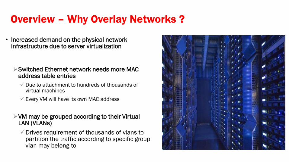
Overview – Why Overlay Networks ?
• Increased demand on the physical network infrastructure due to server virtualization
Switched Ethernet network needs more MAC address table entries
Due to attachment to hundreds of thousands of virtual machines
Every VM will have its own MAC address
VM may be grouped according to their Virtual LAN (VLANs)
Drives requirement of thousands of vlans to partition the traffic according to specific group vlan may belong to
Overview – Why Overlay Networks ?
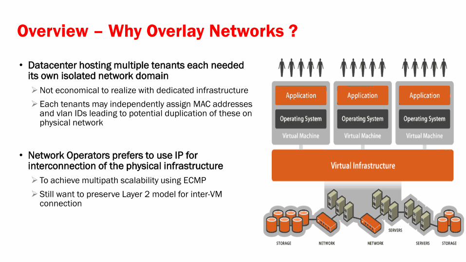
• Datacenter hosting multiple tenants each needed its own isolated network domain
Not economical to realize with dedicated infrastructure
Each tenants may independently assign MAC addresses and vlan IDs leading to potential duplication of these on physical network
• Network Operators prefers to use IP for interconnection of the physical infrastructure
To achieve multipath scalability using ECMP
Still want to preserve Layer 2 model for inter-VM connection
Agenda
• Overview
• Existing Challenges
• Proposed Solutions • IETF VxLAN
Concepts & Deployment Case Studies
• IETF OTV
Concepts & Deployment Case Studies
• IETF MAC VPN
Concepts & Deployment Case Studies
Existing Challenges with Layer 2 DataCenter
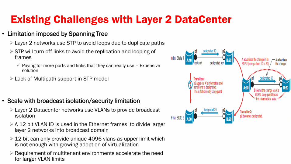
• Limitation imposed by Spanning Tree
Layer 2 networks use STP to avoid loops due to duplicate paths
STP will turn off links to avoid the replication and looping of frames
Paying for more ports and links that they can really use – Expensive solution
Lack of Multipath support in STP model
• Scale with broadcast isolation/security limitation
Layer 2 Datacenter networks use VLANs to provide broadcast isolation
A 12 bit VLAN ID is used in the Ethernet frames to divide larger layer 2 networks into broadcast domain
12 bit can only provide unique 4096 vlans as upper limit which is not enough with growing adoption of virtualization
Requirement of multitenant environments accelerate the need for larger VLAN limits
Existing Challenges with Layer 2 DataCenter
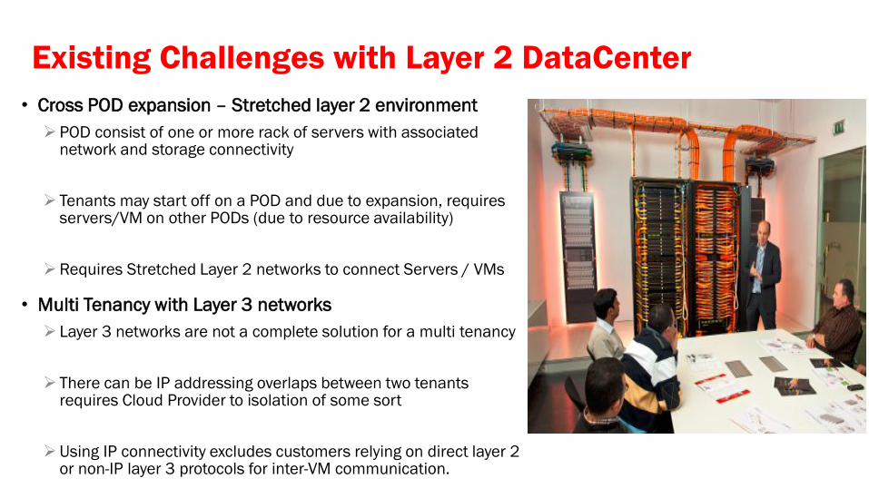
• Cross POD expansion – Stretched layer 2 environment
POD consist of one or more rack of servers with associated network and storage connectivity
Tenants may start off on a POD and due to expansion, requires servers/VM on other PODs (due to resource availability)
Requires Stretched Layer 2 networks to connect Servers / VMs
• Multi Tenancy with Layer 3 networks
Layer 3 networks are not a complete solution for a multi tenancy
There can be IP addressing overlaps between two tenants requires Cloud Provider to isolation of some sort
Using IP connectivity excludes customers relying on direct layer 2 or non-IP layer 3 protocols for inter-VM communication.
Existing Challenges with Layer 2 DataCenter
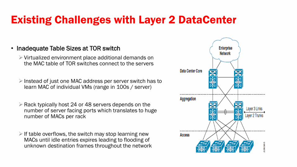
• Inadequate Table Sizes at TOR switch
Virtualized environment place additional demands on the MAC table of TOR switches connect to the servers
Instead of just one MAC address per server switch has to learn MAC of individual VMs (range in 100s / server)
Rack typically host 24 or 48 servers depends on the number of server facing ports which translates to huge number of MACs per rack
If table overflows, the switch may stop learning new MACs until idle entries expires leading to flooding of unknown destination frames throughout the network
Agenda
• Overview
• Existing Challenges
• Proposed Solutions • IETF VxLAN
• Concepts & Deployment Case Studies
• IETF OTV
• Concepts & Deployment Case Studies
• IETF MAC VPN
• Concepts & Deployment Case Studies
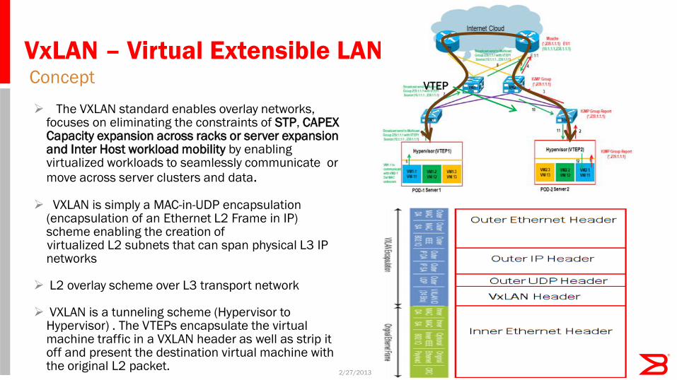
VxLAN – Virtual Extensible LAN Concept
2/27/2013 11
The VXLAN standard enables overlay networks,
focuses on eliminating the constraints of STP, CAPEX Capacity expansion across racks or server expansion and Inter Host workload mobility by enabling virtualized workloads to seamlessly communicate or
move across server clusters and data. VXLAN is simply a MAC-in-UDP encapsulation
(encapsulation of an Ethernet L2 Frame in IP) scheme enabling the creation of
virtualized L2 subnets that can span physical L3 IP networks
L2 overlay scheme over L3 transport network
VXLAN is a tunneling scheme (Hypervisor to
Hypervisor) . The VTEPs encapsulate the virtual machine traffic in a VXLAN header as well as strip it off and present the destination virtual machine with the original L2 packet.
VTEP
Life of a Packet Summary of Data Path communication
2/27/2013 12
• ARP Resolution between VTEPs hosting VMs Communication between two VMs happens over IP networks Hence two VMs to communicate with each other needs ARP resolution aka MAC to IP Mapping
with VxLAN, Broadcast packets are sent to IP Multicast group over which VxLAN overlay network is realized
Mapping is created between VLAN VNI and IP multicast group
• Unicast Communication using MAC-in-UDP Encapsulation
After ARP is resolved VM to VM communication happens over layer 3
VTEP slaps encapsulation transparent to communicating VMs
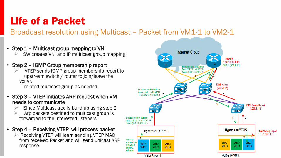
Life of a Packet Broadcast resolution using Multicast – Packet from VM1-1 to VM2-1
2/27/2013 13
• Step 1 – Multicast group mapping to VNI
SW creates VNI and IP multicast group mapping
• Step 2 – IGMP Group membership report VTEP sends IGMP group membership report to upstream switch / router to join/leave the
VxLAN related multicast group as needed
• Step 3 – VTEP initiates ARP request when VM needs to communicate Since Multicast tree is build up using step 2 Arp packets destined to multicast group is
forwarded to the interested listeners
• Step 4 – Receiving VTEP will process packet Receiving VTEP will learn sending VTEP MAC
from received Packet and will send unicast ARP response
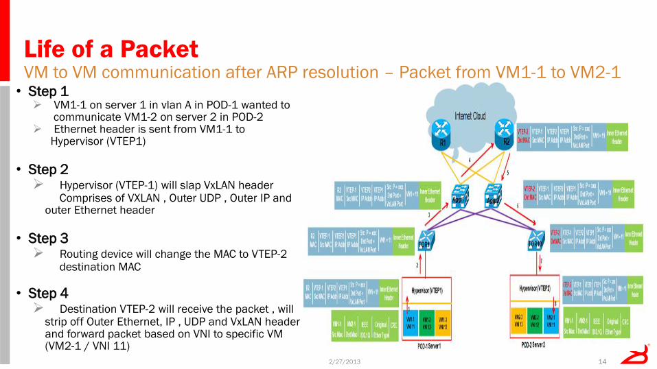
Life of a Packet VM to VM communication after ARP resolution – Packet from VM1-1 to VM2-1
2/27/2013 14
• Step 1
VM1-1 on server 1 in vlan A in POD-1 wanted to communicate VM1-2 on server 2 in POD-2 Ethernet header is sent from VM1-1 to Hypervisor (VTEP1)
• Step 2 Hypervisor (VTEP-1) will slap VxLAN header Comprises of VXLAN , Outer UDP , Outer IP and
outer Ethernet header
• Step 3 Routing device will change the MAC to VTEP-2 destination MAC
• Step 4 Destination VTEP-2 will receive the packet , will
strip off Outer Ethernet, IP , UDP and VxLAN header and forward packet based on VNI to specific VM (VM2-1 / VNI 11)
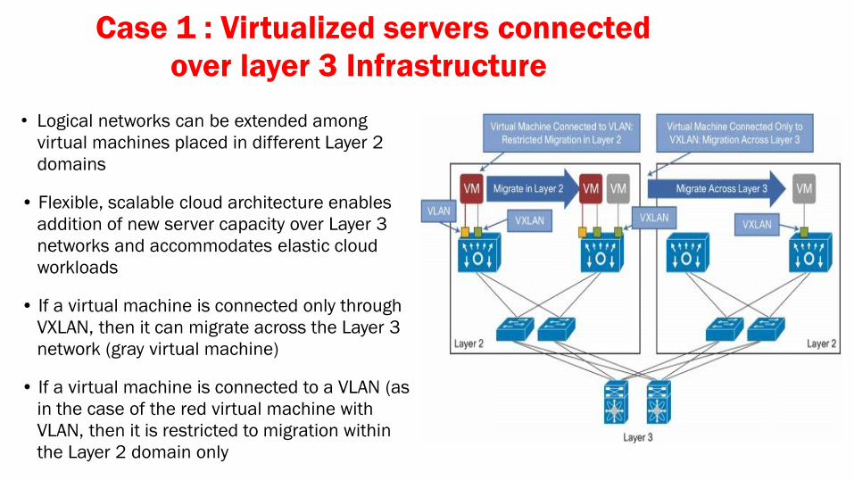
Case 1 : Virtualized servers connected
over layer 3 Infrastructure
• Logical networks can be extended among
virtual machines placed in different Layer 2
domains
• Flexible, scalable cloud architecture enables
addition of new server capacity over Layer 3
networks and accommodates elastic cloud
workloads
• If a virtual machine is connected only through
VXLAN, then it can migrate across the Layer 3
network (gray virtual machine)
• If a virtual machine is connected to a VLAN (as
in the case of the red virtual machine with
VLAN, then it is restricted to migration within
the Layer 2 domain only
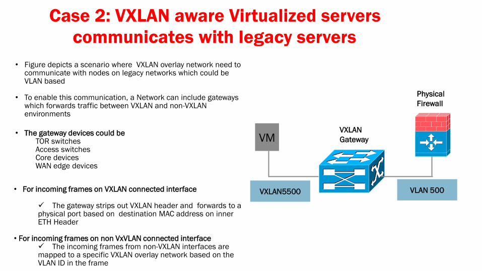
Case 2: VXLAN aware Virtualized servers
communicates with legacy servers
• Figure depicts a scenario where VXLAN overlay network need to communicate with nodes on legacy networks which could be VLAN based
• To enable this communication, a Network can include gateways which forwards traffic between VXLAN and non-VXLAN environments
• The gateway devices could be
TOR switches Access switches Core devices WAN edge devices
VXLAN
Gateway VM
VXLAN5500 VLAN 500
Physical
Firewall
• For incoming frames on VXLAN connected interface The gateway strips out VXLAN header and forwards to a physical port based on destination MAC address on inner ETH Header
• For incoming frames on non VxVLAN connected interface
The incoming frames from non-VXLAN interfaces are mapped to a specific VXLAN overlay network based on the VLAN ID in the frame
Agenda
• Overview
• Existing Challenges
• Proposed Solutions • IETF VxLAN
• Concepts & Deployment Case Studies
• IETF OTV
• Concepts & Deployment Case Studies
• IETF MAC VPN
• Concepts & Deployment Case Studies
OTV – Overlay Transport Virtualization Concept
2/27/2013 18
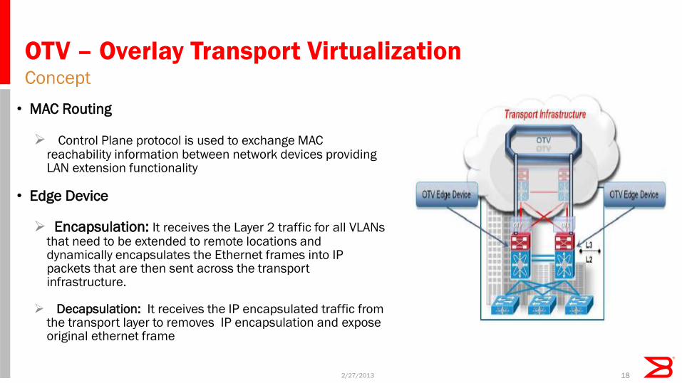
• MAC Routing Control Plane protocol is used to exchange MAC
reachability information between network devices providing LAN extension functionality
• Edge Device Encapsulation: It receives the Layer 2 traffic for all VLANs
that need to be extended to remote locations and dynamically encapsulates the Ethernet frames into IP packets that are then sent across the transport infrastructure.
Decapsulation: It receives the IP encapsulated traffic from the transport layer to removes IP encapsulation and expose original ethernet frame
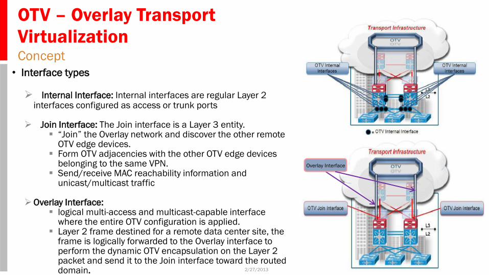
Join Interface: The Join interface is a Layer 3 entity. “Join” the Overlay network and discover the other remote
OTV edge devices. Form OTV adjacencies with the other OTV edge devices
belonging to the same VPN. Send/receive MAC reachability information and
unicast/multicast traffic
Overlay Interface: logical multi-access and multicast-capable interface
where the entire OTV configuration is applied. Layer 2 frame destined for a remote data center site, the
frame is logically forwarded to the Overlay interface to perform the dynamic OTV encapsulation on the Layer 2 packet and send it to the Join interface toward the routed domain.
Overlay Interface
OTV – Control Plane Functionality Concept - Multicast Enabled Transport
2/27/2013 20
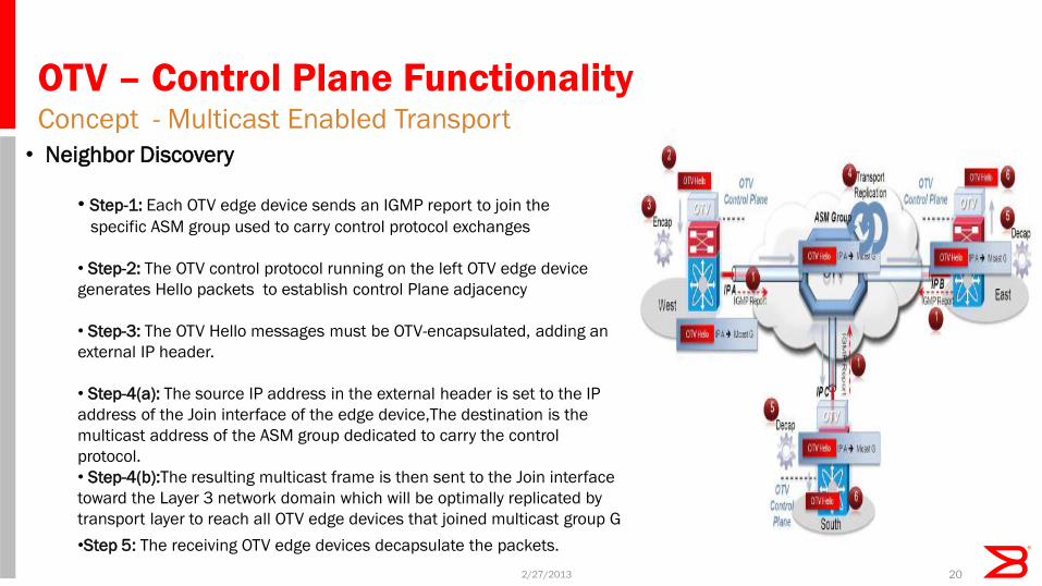
• Neighbor Discovery
• Step-1: Each OTV edge device sends an IGMP report to join the
specific ASM group used to carry control protocol exchanges
• Step-2: The OTV control protocol running on the left OTV edge device
generates Hello packets to establish control Plane adjacency
• Step-3: The OTV Hello messages must be OTV-encapsulated, adding an
external IP header.
• Step-4(a): The source IP address in the external header is set to the IP
address of the Join interface of the edge device,The destination is the
multicast address of the ASM group dedicated to carry the control
protocol.
• Step-4(b):The resulting multicast frame is then sent to the Join interface
toward the Layer 3 network domain which will be optimally replicated by
transport layer to reach all OTV edge devices that joined multicast group G
•Step 5: The receiving OTV edge devices decapsulate the packets.
OTV – Control Plane Functionality Concept - Multicast Enabled Transport
2/27/2013 21
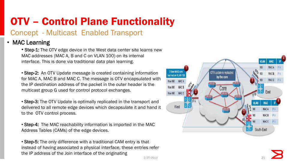
• MAC Learning
• Step-1: The OTV edge device in the West data center site learns new
MAC addresses (MAC A, B and C on VLAN 100) on its internal
interface. This is done via traditional data plan learning.
• Step-2: An OTV Update message is created containing information
for MAC A, MAC B and MAC C. The message is OTV encapsulated with
the IP destination address of the packet in the outer header is the
multicast group G used for control protocol exchanges.
• Step-3: The OTV Update is optimally replicated in the transport and
delivered to all remote edge devices which decapsulate it and hand it
to the OTV control process.
• Step-4: The MAC reachability information is imported in the MAC
Address Tables (CAMs) of the edge devices.
• Step-5: The only difference with a traditional CAM entry is that
instead of having associated a physical interface, these entries refer
the IP address of the Join interface of the originating
OTV – Control Plane Functionality Concept - Unicast-only Transport
2/27/2013 22
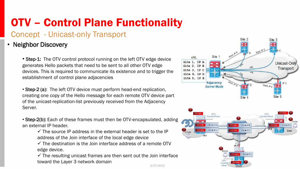
• Neighbor Discovery
• Step-1: The OTV control protocol running on the left OTV edge device
generates Hello packets that need to be sent to all other OTV edge
devices. This is required to communicate its existence and to trigger the
establishment of control plane adjacencies
• Step-2 (a): The left OTV device must perform head-end replication,
creating one copy of the Hello message for each remote OTV device part
of the unicast-replication-list previously received from the Adjacency
Server.
• Step-2(b): Each of these frames must then be OTV-encapsulated, adding
an external IP header.
The source IP address in the external header is set to the IP
address of the Join interface of the local edge device
The destination is the Join interface address of a remote OTV
edge device.
The resulting unicast frames are then sent out the Join interface
toward the Layer 3 network domain
OTV – Control Plane Functionality Concept - Unicast-only Transport
2/27/2013 23
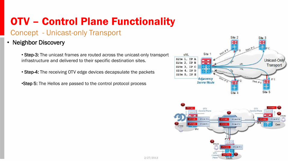
• Neighbor Discovery
• Step-3: The unicast frames are routed across the unicast-only transport
infrastructure and delivered to their specific destination sites.
• Step-4: The receiving OTV edge devices decapsulate the packets
•Step 5: The Hellos are passed to the control protocol process
OTV – Control Plane Functionality Concept - Unicast-only Transport
2/27/2013 24
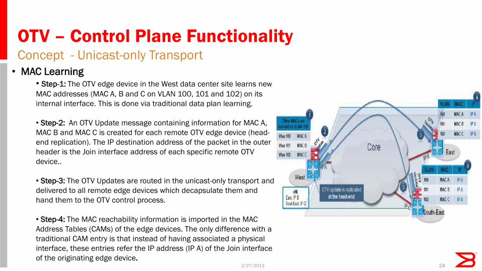
• MAC Learning
• Step-1: The OTV edge device in the West data center site learns new
MAC addresses (MAC A, B and C on VLAN 100, 101 and 102) on its
internal interface. This is done via traditional data plan learning.
• Step-2: An OTV Update message containing information for MAC A,
MAC B and MAC C is created for each remote OTV edge device (head-
end replication). The IP destination address of the packet in the outer
header is the Join interface address of each specific remote OTV
device..
• Step-3: The OTV Updates are routed in the unicast-only transport and
delivered to all remote edge devices which decapsulate them and
hand them to the OTV control process.
• Step-4: The MAC reachability information is imported in the MAC
Address Tables (CAMs) of the edge devices. The only difference with a
traditional CAM entry is that instead of having associated a physical
interface, these entries refer the IP address (IP A) of the Join interface
of the originating edge device.
OTV – Data Plane Functionality Concept - Intra Site Traffic Forwarding
2/27/2013 25
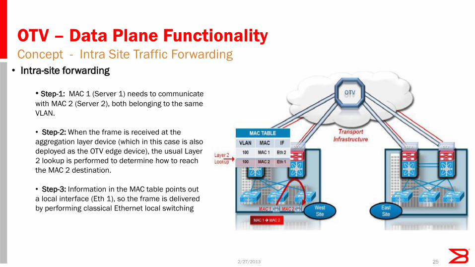
• Intra-site forwarding
• Step-1: MAC 1 (Server 1) needs to communicate
with MAC 2 (Server 2), both belonging to the same
VLAN.
• Step-2: When the frame is received at the
aggregation layer device (which in this case is also
deployed as the OTV edge device), the usual Layer
2 lookup is performed to determine how to reach
the MAC 2 destination.
• Step-3: Information in the MAC table points out
a local interface (Eth 1), so the frame is delivered
by performing classical Ethernet local switching
OTV – Data Plane Functionality Concept - Inter-Site Traffic Forwarding
2/27/2013 26
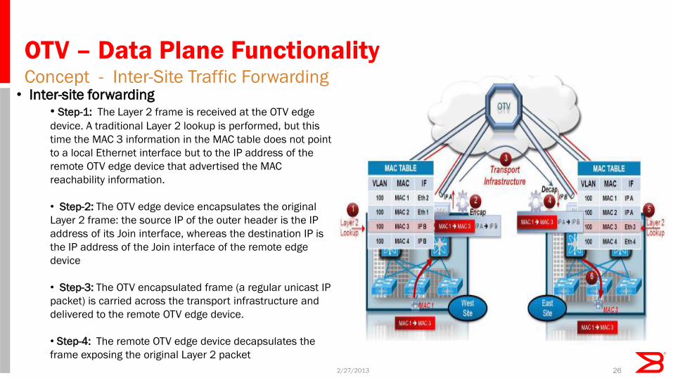
• Inter-site forwarding
• Step-1: The Layer 2 frame is received at the OTV edge
device. A traditional Layer 2 lookup is performed, but this
time the MAC 3 information in the MAC table does not point
to a local Ethernet interface but to the IP address of the
remote OTV edge device that advertised the MAC
reachability information.
• Step-2: The OTV edge device encapsulates the original
Layer 2 frame: the source IP of the outer header is the IP
address of its Join interface, whereas the destination IP is
the IP address of the Join interface of the remote edge
device
• Step-3: The OTV encapsulated frame (a regular unicast IP
packet) is carried across the transport infrastructure and
delivered to the remote OTV edge device.
• Step-4: The remote OTV edge device decapsulates the
frame exposing the original Layer 2 packet
OTV – Data Plane Functionality Concept - Inter-Site Traffic Forwarding
2/27/2013 27
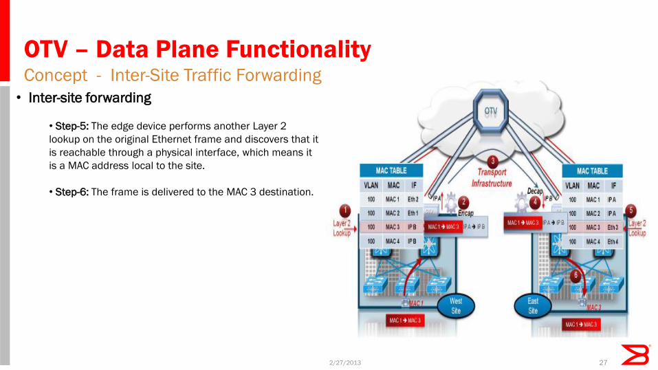
• Inter-site forwarding
• Step-5: The edge device performs another Layer 2
lookup on the original Ethernet frame and discovers that it
is reachable through a physical interface, which means it
is a MAC address local to the site.
• Step-6: The frame is delivered to the MAC 3 destination.
OTV – Deployment Case Study
2/27/2013 28
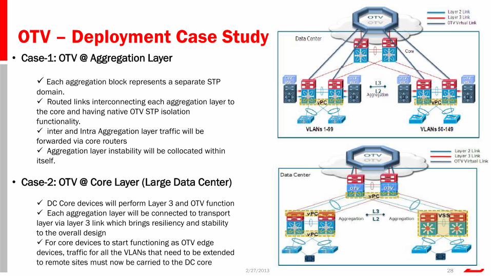
• Case-1: OTV @ Aggregation Layer
Each aggregation block represents a separate STP
domain.
Routed links interconnecting each aggregation layer to
the core and having native OTV STP isolation
functionality.
inter and Intra Aggregation layer traffic will be
forwarded via core routers
Aggregation layer instability will be collocated within
itself.
• Case-2: OTV @ Core Layer (Large Data Center)
DC Core devices will perform Layer 3 and OTV function
Each aggregation layer will be connected to transport
layer via layer 3 link which brings resiliency and stability
to the overall design
For core devices to start functioning as OTV edge
devices, traffic for all the VLANs that need to be extended
to remote sites must now be carried to the DC core
Agenda
• Overview
• Existing Challenges
• Proposed Solutions • IETF VxLAN
• Concepts & Deployment Case Studies
• IETF OTV
• Concepts & Deployment Case Studies
• IETF MAC VPN
• Concepts & Deployment Case Studies
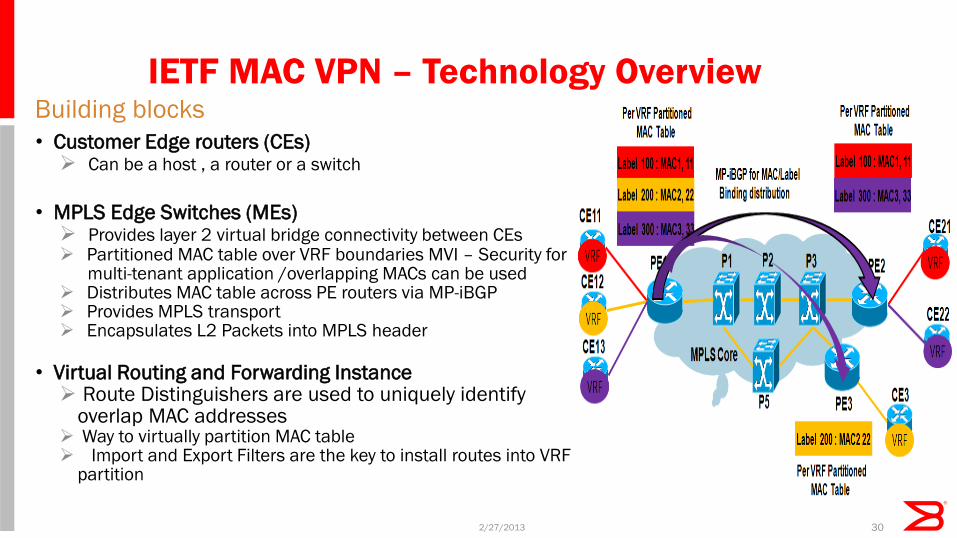
IETF MAC VPN – Technology Overview Building blocks
2/27/2013 30
• Customer Edge routers (CEs) Can be a host , a router or a switch
• MPLS Edge Switches (MEs) Provides layer 2 virtual bridge connectivity between CEs Partitioned MAC table over VRF boundaries MVI – Security for multi-tenant application /overlapping MACs can be used Distributes MAC table across PE routers via MP-iBGP Provides MPLS transport Encapsulates L2 Packets into MPLS header
• Virtual Routing and Forwarding Instance Route Distinguishers are used to uniquely identify
overlap MAC addresses Way to virtually partition MAC table Import and Export Filters are the key to install routes into VRF
partition
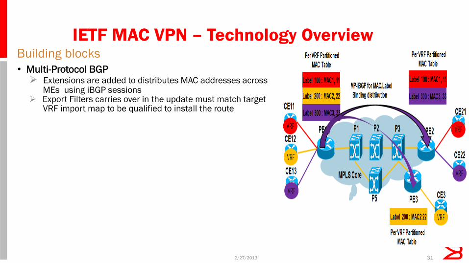
IETF MAC VPN – Technology Overview Building blocks
2/27/2013 31
• Multi-Protocol BGP Extensions are added to distributes MAC addresses across MEs using iBGP sessions Export Filters carries over in the update must match target VRF import map to be qualified to install the route