94
OVERSEAS ROAD NOTE 19 A guide to the design of hot mix asphalt in tropical and sub-tropical countries TRL Limited, Crowthorne, Berkshire, United Kingdom
| Date post: | 08-Nov-2014 |
| Category: |
Documents |
| Upload: | nitish-ramdawor |
| View: | 568 times |
| Download: | 116 times |

OVERSEASROAD NOTE
19
A guide to the design of hot mixasphalt in tropical and sub-tropicalcountries
TRL Limited, Crowthorne, Berkshire, United Kingdom

A guide to the design of hot mix asphalt intropical and sub-tropical countries
TRL Limited Department for International DevelopmentOld Wokingham Road 1 Palace StreetCrowthorne, Berkshire, RG45 6AU London, SW1E 5HEUnited Kingdom
ORN 19
Overseas Road Note 19

First Published 2002ISSN 0951-8797Copyright TRL Limited 2002.
This document is an output from a project funded by the UKDepartment for International Development (DFID) for thebenefit of developing countries. The views expressed in it arenot necessarily those of the DFID.
Subsector: Transport
Theme: T2
Project title: Dense bituminous surfacings for developing countries: A guide
Project reference: R6897
TRL is committed to optimising energy efficiency, reducingwaste and promoting recycling and re-use. In support of theseenvironmental goals, this report has been printed on recycledpaper, comprising 100% post-consumer waste, manufacturedusing a TCF (totally chlorine free) process.

ACKNOWLEDGEMENTS
This Road Note has been produced in the International Division of TRL (Director Mr S W Colwill) on behalf ofthe Department for International Development. The research has been carried out with the active collaboration ofhighway authorities in many countries and their help and co-operation has been essential to the success of theproject. TRL are particularly grateful for the assistance given by the Ministry of Communications andWorks in Kenya and Jabatan Kerja Raya (Ministry of Works) in Malaysia.
The TRL project team responsible for this Road Note were Mr C R Jones (Project Officer), Mr H R Smith,Mr A C Edwards, Mr W G Ford, Dr J Rolt, and Dr A B Sterling. The helpful comments of Mr D Walker of theAsphalt Institute, Dr J Oliver of ARRB Transport Research, Mr J Rebecci of Roadcore Pty Ltd, andMr D Rossman of the South African National Roads Agency Ltd are gratefully acknowledged. Wherenecessary, use has been made of work published by other research and road authorities.
OVERSEAS ROAD NOTES
Overseas Road Notes are prepared principally for road and transport authorities in countries receiving technicalassistance from the British Government. A limited number of copies is available to other organisations and toindividuals with an interest in roads overseas, and may be obtained from:
International DivisionTRL LimitedCrowthorne, Berkshire, RG45 6AUUnited Kingdom
Limited extracts from the text may be reproduced provided the source is acknowledged. For more extensivereproduction, please write to the address given above.
i

ii
Foreword
Roads are vital to economic development, but can be very expensive, especially if the performance of the road’ssurface is poor. It is therefore important that suitable methods of design are developed for the wide range ofconditions that road surfaces are expected to endure. The principal roads in most countries are surfaced with hot-mixed asphalt (HMA) i.e. a mixture of aggregate materials bound together with bitumen. The development oftechniques for designing and constructing such surfaces has relied primarily on empirical methods rather than ona fundamental understanding of the physical interactions that take place. Such surfaces have proved to bereasonably successful, especially in temperate climates where the climatic conditions are not severe and wheresufficient empirical evidence has been collected for reliable and reproducible designs to have evolved.
Road conditions are, however, not static; for example, continuing developments in vehicle and tyre designs oftenincrease the stresses that are applied to the road. In most countries traffic levels are also increasing, sometimesbeyond the limits of the empirical data on which designs are based. In some countries there is a shortage ofmaterials of sufficient quality for road surfaces and therefore innovative solutions need to be sought.Environmental concerns are becoming increasingly important and influence the techniques available; forexample, encouraging the recycling of existing materials. For these reasons, amongst others, research intoimproving the design and performance of HMA road surfaces continues to be undertaken.
In tropical and sub-tropical countries the performance of HMA has often been disappointing, with road surfacessometimes failing within a few months of construction and rarely lasting as long as hoped. Under the hightemperature conditions experienced in these countries, bitumen, which is a visco-elastic material, can becomevery soft. It can also undergo relatively rapid chemical changes that cause many of the desirable properties of theHMA to be degraded or lost altogether. Thus developing a design method for HMA surfacing material thatensures good long-term performance under a wide range of tropical conditions has provided a challenge forresearch engineers and scientists.
This Road Note has been based on the experience of TRL Limited and collaborating organisations throughoutthe world. Most of this experience has been gained in carrying out a comprehensive, co-ordinated and long-termseries of research projects as part of the ‘Knowledge and Research’ programme of the United Kingdom’sDepartment for International Development. The research showed that the behaviour of asphalt surfaces intropical and sub-tropical environments was frequently contrary to expectations and has given rise to a paradigmshift in our understanding of road behaviour. The outcome of the research has provided a new understanding ofthe problems associated with the use of HMA in hot tropical climates and has resulted in the development ofsome practicable methods for overcoming these problems.
This Road Note is aimed at engineers responsible for roads and gives guidance on the design, manufacture andconstruction of HMA pavement materials in tropical and sub-tropical climates. The HMA requirements aredescribed for different traffic loading categories, including severely loaded sites such as climbing lanes. Theprocedures take into account the fact that many countries have limited facilities for designing bituminous mixesand therefore need to use commonly available or inexpensive equipment. The Road Note complements and, inmany parts, also updates Overseas Road Note 31 (TRL, 1993 which gives recommendations for the design andconstruction of new road pavements but which also includes chapters on the design of pavement layers).
The methods of design that are described in this Road Note remain firmly based on practical experience. Becauseof the wide diversity of road building materials, climates, vehicle flows and vehicle loading characteristics thatmay be encountered, the Road Note also makes reference, where necessary, to the standards and guidancedocuments produced by other international authorities. The importance of local knowledge and the judgement ofexperienced engineers should, however, never be overlooked.
John HodgesChief Engineering AdviserDepartment for International DevelopmentLondon
November 2002
iii

iv
v
CONTENTS
Page
1 Introduction 1
2 Composition of HMA 2
Components of a mix 2
Types of HMA in common use 2
Asphalt Concrete (AC) 2
Bitumen Macadam 2
Hot Rolled Asphalt 2
Other types of mixes 3
3 Factors affecting HMA design 4
Modes of failure of HMA surfacings 4
Cracking in HMA surfacings 4
Failure of asphalt surfacings by plastic deformation 4
Loss of surfacing aggregate, or fretting 5
Effects of vehicle characteristics 5
Axle loads and vehicle speeds 5
Type of tyre 6
Tyre pressures 6
Maintenance 6
Safety considerations 6
4 Materials for HMA 7
Aggregates 7
Bitumen for HMA 7
Pre-hardening of bitumen 7
Requirements for penetration graded bitumens 7
Requirements for viscosity graded bitumens 8
European specifications for paving grade bitumens 8
Bitumen durability 8
5 Mix design for HMA 13
Introduction to mix design methods 13
Volumetric design of HMA mixes 13
Aggregate particle size distributions for HMA 15
Particle size distributions for AC wearing courses 16
Particle size distributions for AC binder courses and roadbases 16
Particle size distributions for Dense Bitumen Macadam (DBM) 17
vi
Page
6 Mix design specifications 19
Mix design for continuously graded wearing courses 19
VMA and bitumen film thickness 19
For design traffic less than 5 million esa 19
For design traffic greater than 5 million esa 19
Other considerations for design of continuously graded mixes 20
Mix design for severe sites 20
Selection of grade of bitumen 21
Use of recycled asphalt 21
7 Mix production 22
General requirements 22
Aggregate stock piles and cold feeds 23
8 Construction of asphalt surfacings 24
Mixing and compaction 24
VIM after construction 24
AC mixes designed by the Marshall method 24
HMA designed by refusal compaction 25
Segregation 25
9 References 26
10 Bibliography 28
11 Some of the AASHTO documents relevant to Superpave™ 29
12 Applicable British Standards for HMA 30
13 Applicable CEN standards for HMA 32
Appendix A: Testing aggregates for use in HMA 35
Appendix B: Testing bitumens for use in HMA 38
Appendix C: Marshall design method and volumetric design 46
Appendix D: Superpave™ 56
Appendix E: Performance tests for HMA design 63
Appendix F: Effect of compaction on design bitumen content 67
Appendix G: Refusal density test using a vibrating hammer 69
Appendix H: Recycling of bituminous materials 73
1
Wearing course
(bituminous)
Binder course
(bituminous)
Surfacing
layers
Road base
(can be bituminous)
Sub-base
(not normally bituminous)
Subgrade
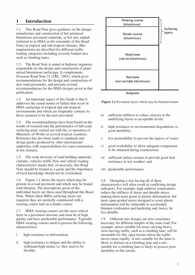
Figure 1.1 Pavement layers which may be bitumen bound
1 Introduction
1.1 This Road Note gives guidance on the design,manufacture and construction of hot premixedbituminous pavement materials, or hot mix asphalt(referred to as HMA in the remainder of this RoadNote) in tropical and sub-tropical climates. Mixrequirements are described for different trafficloading categories including severely loaded sitessuch as climbing lanes.
1.2 The Road Note is aimed at highway engineersresponsible for the design and construction of plant-mixed bituminous surfacings. It complementsOverseas Road Note 31 (TRL, 1993), which givesrecommendations for the design and construction ofnew road pavements, and presents revisedrecommendations for the HMA designs given in thatpublication.
1.3 An important aspect of this Guide is that itaddresses the actual modes of failure that occur inHMA surfacings in tropical and sub-tropicalenvironments and which are frequently contrary tothose assumed to be the most prevalent.
1.4 The recommendations have been based on theresults of research into the performance of full-scalesurfacing trials carried out with the co-operation ofMinistries of Works in several tropical countries.Reference has also been made to standards anddesign guides produced by other internationalauthorities with responsibilities for road constructionin hot climates.
1.5 The wide diversity of road building materials,climates, vehicles traffic flow and vehicle loadingcharacteristics means that, of necessity, this RoadNote should be treated as a guide and the importanceof local knowledge should not be overlooked.
1.6 Figure 1.1 shows the layers which may bepresent in a road pavement and which may be boundwith bitumen. The descriptions given of theindividual layers are those used throughout this RoadNote. Where thick HMA surfacing layers arerequired, they are normally constructed with awearing course laid on a binder course.
1.7 HMA wearing courses are the most criticallayer in a pavement structure and must be of highquality and have predictable performance. TypicallyHMA wearing courses need to possess the followingcharacteristics:
i high resistance to deformation;
ii high resistance to fatigue and the ability towithstand high strains i.e. they need to beflexible;
iii sufficient stiffness to reduce stresses in theunderlying layers to acceptable levels;
iv high resistance to environmental degradation i.e.good durability;
v low permeability to prevent the ingress of water;
vi good workability to allow adequate compactionto be obtained during construction;
vii sufficient surface texture to provide good skidresistance in wet weather; and
viii predictable performance.
1.8 Designing a mix having all of thesecharacteristics will often result in conflicting designindicators. For example, high ambient temperaturesreduce the stiffness of dense and durable mixesmaking them more prone to plastic deformation, butmore open-graded mixes designed to resist plasticdeformation will be vulnerable to acceleratedbitumen oxidisation and hardening and, hence, beless durable.
1.9 Different mix designs are also sometimesnecessary for different lengths of the same road. Forexample, mixes suitable for areas carrying heavy,slow-moving traffic, such as a climbing lane, will beunsuitable for flat, open terrain where the trafficmoves more rapidly. A mix suitable for the latter islikely to deform on a climbing lane and a mixsuitable for a climbing lane is likely to possess poordurability in flat terrain.
2
2 Composition of HMA
Components of a mix
2.1 The types of HMA most frequently used intropical countries are manufactured in an asphaltplant by hot-mixing appropriate proportions of thefollowing materials:
i coarse aggregate, defined as material havingparticles larger than 2.36mm;
ii fine aggregate, defined as material havingparticles less than 2.36mm and larger than0.075mm;
iii filler, defined as material having particle sizesless than 0.075mm, which may originate fromfines in the aggregate or be added in the form ofcement, lime or ground rock; and
iv a paving grade bitumen with viscositycharacteristics appropriate for the type of HMA,the climate and loading conditions where it willbe used.
Note: It should be noted that the Asphalt Institute andseveral international authorities define coarse and fineaggregate with reference to the 2.36mm sieve whilstothers, including AASHTO, refer to the 4.75mm sieve.This should be taken into consideration whenspecifying particular aggregate tests.
Types of HMA in common use
2.2 Two generic types of HMA are presently usedin countries with tropical climates. These are:
i Mixes in which traffic stresses are transmittedmainly through an aggregate structure which hasa continuous particle size distribution. AsphaltConcrete and Bitumen Macadam are examplesof this type.
ii Mixes in which stresses are passed through thefines/filler/bitumen matrix. In these mixes theaggregate particle size distribution isdiscontinuous or ‘gap-graded’. Hot RolledAsphalt is in this category.
Asphalt Concrete (AC)2.3 This is by far the most common type of HMAused in tropical countries and it is usually designedby the Marshall Method (Asphalt Institute, 1994).The material has a continuous distribution ofaggregate particle sizes which is often designed tofollow closely the Fuller curve to give the maximumdensity after compaction. However, such a dense
structure makes AC sensitive to errors in compositionand the effect of this becomes more critical as trafficloads increase.
Bitumen Macadam2.4 This type of HMA, commonly known as DenseBitumen Macadam (DBM), is similar to AC exceptthat the skeleton of the compacted aggregate tends tobe less dense. In Britain, where it is now known asClose Graded Macadam (BS 4987, 1993), it hastraditionally been made to recipe designs and has alsobeen used with success in tropical environments. ThisHMA will be referred to as DBM in this Road Note.
2.5 Recipe specifications and the necessarycompliance testing are simple to use and toimplement, but the transfer of recipe designs betweencountries having different climates, materials andtraffic loading characteristics cannot berecommended because there is no simple procedurefor adequately assessing the effects of thesedifferences. In addition, because recipe specificationsare based on historical performance, modifications tothe specifications tend to be delayed responses tosome change in conditions. Most authorities prefer tohave a test procedure that ensures satisfactoryperformance at all times and hence recipespecifications are not commonly used.
Hot Rolled Asphalt2.6 Hot Rolled Asphalt (HRA) has been usedextensively on heavily trafficked roads in Britain overmany years and also in modified forms in South Africaand Indonesia. However, as the severity of trafficloading has increased there has been a significantincrease in the incidence of rutting. This type of mix isno longer recommended for heavily trafficked roads inSouth Africa and its use is diminishing in the UK. InAustralia HRA is recommended for residential streetsbecause the mix has good workability and it is easy toachieve an impermeable layer.
2.7 In the UK the coarse aggregate content of HRAwearing courses is typically 30 per cent. Bitumencoated chippings must be spread and rolled into thesurfacing during construction to provide good skidresistance. This makes the material relativelyexpensive. HRA can be made to a less expensivedesign suitable for many roads in tropical climates byincreasing the coarse aggregate content to between 45and 55 per cent. This minimises the quantity of therelatively expensive sand/filler/bitumen mortar andavoids the need to apply coated chippings.
2.8 HRA has several advantages compared to AC.It is less sensitive to proportioning, making it easierto manufacture, and it is also easier to lay andcompact. It requires fewer aggregate sizes andtherefore fewer stockpiles and cold feed bins.
3
2.9 Unlike AC mixes, the aggregate particle sizedistribution is discontinuous and is referred to asbeing ‘gap-graded’. It is the properties of the sand/filler/bitumen matrix that determines theperformance characteristics of the mix. The gap inthe particle size distribution is obtained by limitingthe quantity of aggregate particles between 2.36mmand 0.6mm in size. This requirement is relativelyeasy to comply with when fine pit-sand is availablebut can otherwise be difficult to achieve, especiallywhere the available rock is difficult to crush.
2.10 Authorities who are considering the use ofHRA should refer to the appropriate Australian andSouth African specifications.
Other types of mixes2.11 The wear and tear on wearing course layers isoften severe and these layers need to be replacedperiodically to maintain desirable surface characteristicssuch as high skid resistance. Commercial companieshave developed ‘thin surfacing’ mixes which aresuitable for this type of application. These proprietarymaterials sometimes contain a modified bitumen, andmay also include a high filler content or fibres. Forrehabilitation purposes, some are able to provide alimited amount of correction to a deformed surface, butthis is only applicable where the existing wearing courseis stable and not deforming plastically. It is alsoimportant that the existing pavement is structurallysound and that there is little or no full depth cracking inthe asphalt layer.
4
7
6
5
Bitu
me
n v
isco
sity 4
5ºC
(L
og
10p
ois
es)
0 10 20 30
Mean depth below surface (mm)
Air voids
in core %
5.7
1.4
2.7
AFTER 24 MONTHS EXPOSURE
Figure 3.1 Bitumen viscosity versus depth in cores takenfrom a road site
3 Factors affecting HMA design
Modes of failure of HMA surfacings
3.1 Traditionally HMA has been designed to resistthree main modes of deterioration. These modes ofdeterioration are:
i fatigue cracking;
ii plastic deformation; and
iii loss of surfacing aggregate.
Cracking in HMA surfacings3.2 Fatigue cracking results from the cumulativeeffect of horizontal tensile strains generated byapplications of heavy vehicle loads and is expected tobe initiated at, or near to, the bottom of the HMAlayer where the induced tensile strains are greatest.However, investigations carried out by TRL in co-operation with Ministries of Works in severalcountries have shown that this type of fatiguecracking is comparatively rare and is virtually alwayspreceded by cracking which initiates at the surface ofthe layer (Rolt et al., 1986, Smith et al., 1990, Strausset al., 1984, Dauzats and Linder, 1982). It is nowgenerally accepted that ‘top down’ cracking occurs inmany countries including those with more temperateclimates (Nunn et al., 1997).
3.3 ‘Top-down’ cracking is associated with agehardening of bitumen in the top few millimetres ofthe wearing course and, in the tropics, can developrelatively early in the expected life of the surfacing.The important point is that it is not necessarily a signof structural inadequacy. The hardened ‘skin’ of thesurfacing is very brittle and may crack as a result ofthermal or traffic induced strains or by a combinationof the two. The fact that widespread ‘top-down’cracking often occurs in asphalt surfacing onuntrafficked areas of airfields points to theimportance of environmental effects and thermalstresses. Figure 3.1 shows an example of agehardening. In this dense AC wearing course, locatedin a seasonally hot and dry (but not extreme) climate,a steep viscosity gradient has developed in thebitumen within two years of construction. Severehardening is apparent in the top few millimetres ofthe material with the viscosity of the bitumenincreasing from approximately 4.85 to 6.7 log poises(or 7.5x10⁴ to 5x10⁶ poises). Over the range studiedthe increase in viscosity at the surface was found tobe independent of the percentage of voids in thematerial itself.
3.4 One way of improving the durability of HMAis to increase the bitumen content. This reduces theair void content and the rate of oxygen absorption(Dickinson, 1984) and any surface cracking in the
bitumen-rich mix is likely to remain shallow forsome considerable time. However, using a bitumen-rich mix on roads carrying more than light trafficintroduces a high risk of more serious failure throughplastic deformation.
Failure of asphalt surfacings by plastic deformation3.5 Plastic deformation in HMA surfacings is themost serious form of failure because the affectedmaterial must be removed before the road can berehabilitated. It is usually associated with anunderestimate of the degree of secondarycompaction that occurs under heavy traffic whichreduces the air voids content, or voids in the mix(VIM), to a critical level at which plasticdeformation occurs relatively rapidly.
3.6 The relationship between in situ VIM andasphalt deformation observed on severely loadedsites in countries experiencing high roadtemperatures is illustrated in Figure 3.2 It can be seenthat it is necessary to ensure that VIM remainsgreater than 3 per cent if plastic deformation is to beavoided. This is in agreement with therecommendations of the Asphalt Institute (AsphaltInstitute, MS-2, 1994).
3.7 When the VIM in an AC layer decreases toless than approximately 3 per cent, stress transfer,which was occurring through stone to stone contactin the coarse aggregate, switches to the bitumen-finescomponent in the mix. As secondary compactioncontinues, stone to stone contact is increasinglyreduced until plastic deformation occurs.
5
Days after construction
Vo
ids in
mix
(%
)
0 200 400 600 800
1
2
3
4
5
6
7
8
9
10
Mix 1
Mix 3
Mix 4
Mix 2
0
Figure 3.3 Reduction in VIM in the wheelpath of AC wearing courses designed by Marshall procedure
Figure 3.2 Occurrence of plastic deformation in AC wearing courses
3.8 Typical relationships between the rate ofreduction in VIM and traffic on a climbing lane areshown in Figure 3.3 (Hizam and Jones, 1992).
Loss of surfacing aggregate, or fretting3.9 This is often associated with the scrubbingaction of vehicle tyres and may develop because of:
i the use of an incorrect aggregate particle sizedistribution, segregation, or inadequatecompaction. These can result in a permeablesurface leading to rapid embrittlement of thebitumen and stones breaking away from thesurfacing layer;
ii the use of a low bitumen content making themixture less durable;
iii the general embrittlement of the bitumen nearthe end of the design life of the wearing course;
iv ‘stripping’ resulting from ingress of water andpoor adhesion between the bitumen andaggregate particles.
Effects of vehicle characteristics
Axle loads and vehicle speeds3.10 Traffic loading for pavement design purposesis expressed in terms of equivalent standard axles(esa). As the design esa increases, so the thickness ofthe HMA layers increase in order to accommodatethe greater cumulative loading. Whilst the magnitudeof axle loads are important it is the characteristicsand pressure of the tyre that have most influence onthe performance of HMA.
0 1 2 3 4 5 6 7 8 9 10
Voids in mix (VIM %)
East Africa
Malaysia
No plastic
deformation
Middle East
Plastic
deformationIncreasedprobability of
plastic deformation
Decreasedprobability of plastic deformation
6
3.11 Vehicle speeds determine the loading timewhich, in turn, will also affect the performance ofHMA surfacings. Under slow moving heavy vehiclesthe longer loading time results in an effectivereduction in the stiffness of the HMA and increasedsecondary compaction. Therefore, an HMA which issuitable for climbing lanes will retain higher VIMwhen used on flat terrain, where vehicles speeds arehigher, and will be less durable.
Type of tyre3.12 Greater use of radial ply tyres has increased theseverity of traffic loading. On roads which carry hightraffic it is common for the vehicles to be‘channelled’ and to form distinct wheelpaths. Wherethis concentrated loading causes even a shallow rut toform, the traffic loading can become even moreconcentrated. In the past, cross ply (or biased) tyrestended to ‘climb out’ of any rut that formed, therebydistributing vehicle loads over a relatively widewheelpath. However, radial ply tyres tend to run inthe bottom of the ruts (Gillespie et al., 1993) therebyproducing much narrower wheelpaths and moreintensive traffic loading. The complexity ofpredicting the effects of traffic loading has also beenincreased by the introduction of wide-based singletyres (sometimes called super singles), whosedamaging effect appears to depend, not surprisingly,upon their width.
Tyre pressures3.13 Tyre pressures have also increased significantlyover recent years and this has resulted in more severeloading at the road surface. The unpublished results ofa survey, carried out in 1987 by the Ministry of Worksand Housing in Kenya showed that, typically, the tyrepressure of 0.48 MPa (70 psi) used at the AASHORoad Test (HRB, 1962) approximated to the lower 10percentile tyre pressure of heavy commercial vehiclesin Kenya. The mean value recorded during the studywas 0.7MPa (102 psi) and the highest wasapproximately 1.03MPa (150 psi).
Maintenance
3.14 Roads with HMA surfacings are normallydesigned for 10 to 20 years of trafficking, with 15years being a typical target. Frequently roads withHMA surfacings in tropical climates suffer crackinglong before their design lives have been reached, butthe running surface can remain relatively smoothuntil the cracks propagate to the bottom of the HMA.At this stage, water ingress into lower granularmaterials usually leads to rapid structural damage.The problem then is that maintenance funds cannotbe raised quickly enough to prevent the need formajor rehabilitation work.
3.15 It is therefore important that maintenance iscarried out before significant damage occurs to theroadbase. The optimum timing and frequency ofmaintenance is difficult to predict sufficientlyaccurately from a project level analysis since it willdepend upon many factors such as the properties ofthe HMA surfacing material, climate and traffic but,typically, a seal is often required within five years oflaying an HMA surfacing.
3.16 In countries where it is unlikely that funds willbe available to carry out such maintenance, it will becost effective to seal the HMA as part of theconstruction process. If this procedure is adoptedthen the use of binder course HMA will be acceptableand may be cheaper than a finer wearing coursematerial. A binder course mix normally has a higherpercentage of large sized aggregate than a wearingcourse mix and will be more resistant to theembedment of chippings in early life. However,whichever type of mix is used, the design of a surfacedressing must take into account the hardness of thenew HMA surfacing (TRL, 2000). A short delay maybe necessary to allow the surfacing to harden beforethe dressing is applied.
3.17 A surface dressing placed soon afterconstruction will prevent the formation of a steepbitumen viscosity gradient in the surface of thewearing course and significantly reduce the risk ofearly cracking. However, if such a seal is constructedwhen deterioration is already evident, then at leastone seal, preferably a double seal, should bebudgeted for to achieve a 15-year design life and afurther reseal for a 20-year design life. Once top-down cracking becomes too severe or extensive, thenmilling off and replacing the wearing course may bea cheaper, or preferred, maintenance option.
Safety considerations
3.18 In developing countries safety considerationsare not always given the priority they merit duringthe manufacture and construction of HMA wearingcourses. To provide good skid resistance propertiesduring wet weather a wearing course must have agood surface texture to prevent aquaplaning at highspeed. The coarse aggregate should also have goodresistance to polishing to reduce the probability ofslow speed skidding.
7
4 Materials for HMA
4.1 It is essential that the properties of the componentmaterials of HMA meet minimum standards to ensurethe material has a satisfactory performance.
Aggregates
4.2 Aggregate is the major component in HMAand the quality and physical properties of thismaterial has a large influence on mix performance.Typically the qualities required of aggregates aredescribed in terms of shape, hardness, durability,cleanliness, bitumen affinity and porosity. In additionto these properties, the micro texture of the aggregateparticles will also strongly influence the performanceof a compacted HMA layer. Smooth-surfaced rivergravel, even partly crushed, may not generate asmuch internal friction as a totally crushed aggregatewith particles having a coarse micro texture.
4.3 The coarse aggregates used for making HMAshould be produced by crushing sound, unweatheredrock or natural gravel. Gravel should be crushed toproduce at least two fractured faces on each particle.
4.4 The aggregate should have the followingcharacteristics:
! be clean and free of clay and organic material;
! be angular and not excessively flaky, to providegood mechanical interlock;
! be strong enough to resist crushing duringmixing and laying as well as in service;
! be resistant to abrasion and polishing whenexposed to traffic;
! be non absorptive - highly absorptive aggregatesare wasteful of bitumen and also give rise toproblems in mix design; and
! have good affinity with bitumen - hydrophilicaggregates may be acceptable only whereprotection from water can be guaranteed, or asuitable adhesion agent is used.
4.5 Filler (material finer than 0.075 mm) can becrushed rock fines, Portland cement or hydrated lime.Portland cement or hydrated lime is often added tonatural filler (1-2 per cent by mass of total mix) toimprove the adhesion of the bitumen to the aggregate.
4.6 Filler has an important effect on voids contentand the stiffness of the bitumen-fines matrix. The SGof the filler must be taken into account because, forinstance, equal masses of Portland cement and freshhydrated lime will have very different bulk volumesand, therefore, different effects on mix properties.
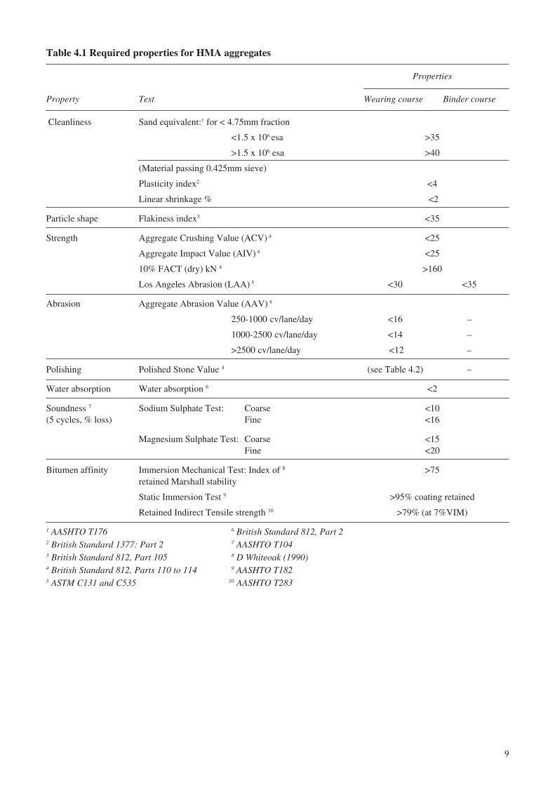
4.7 The required properties for aggregates aregiven in Table 4.1 and summaries of the relevant testmethods are given in Appendix A.
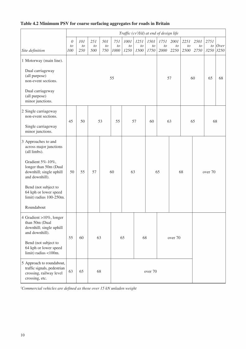
4.8 In the UK detailed specifications have beendeveloped for the Polished Stone Value required atsites which present different degrees of risk(Department of Transport, UK (1994). Thesespecifications are reproduced in Table 4.2.
Bitumen for HMA
4.9 There are three important properties orcharacteristics of paving grade bitumens. These areconsistency (usually called viscosity), purity and safety.
4.10 Traditionally, paving grade bitumens have beenspecified in term of their penetration, but themeasurement of viscosity provides a more accuratemethod of specifying binder consistency and a moreeffective method of determining the temperaturesusceptibility of the bitumen. This allows the mostappropriate mixing and compaction temperature forthe asphalt mix to be established by using the BitumenTest Data Chart (BTDC) developed by Heukelom(1969)(1973), which is illustrated in Appendix B.
4.11 Several authorities now produce alternativespecifications based on viscosity. Suitable apparatusfor measuring viscosity may not be readily availablein developing countries and, therefore, both methodsof specification are presented below. When orderingbulk bitumen supplies, it should be possible to obtainevidence of compliance with viscosity specificationssince the necessary equipment will be available at therefinery.
Pre-hardening of bitumen4.12 Bitumen samples should be tested in both the‘as delivered state’ and also after pre-hardening,which is intended to simulate the ageing of a bitumenduring storage, mixing and construction. Two testmethods are used to pre-age bitumen, the Thin FilmOven Test (TFOT) and the Rolling Thin Film OvenTest (RTFOT). The RTFOT test is considered to bethe best method of simulating the ageing of bitumenduring the construction process but, again, thisapparatus may not be readily available. The TFOTcan be used for penetration graded specifications but,where possible, the RTFOT equipment and aviscosity graded specification should be used.
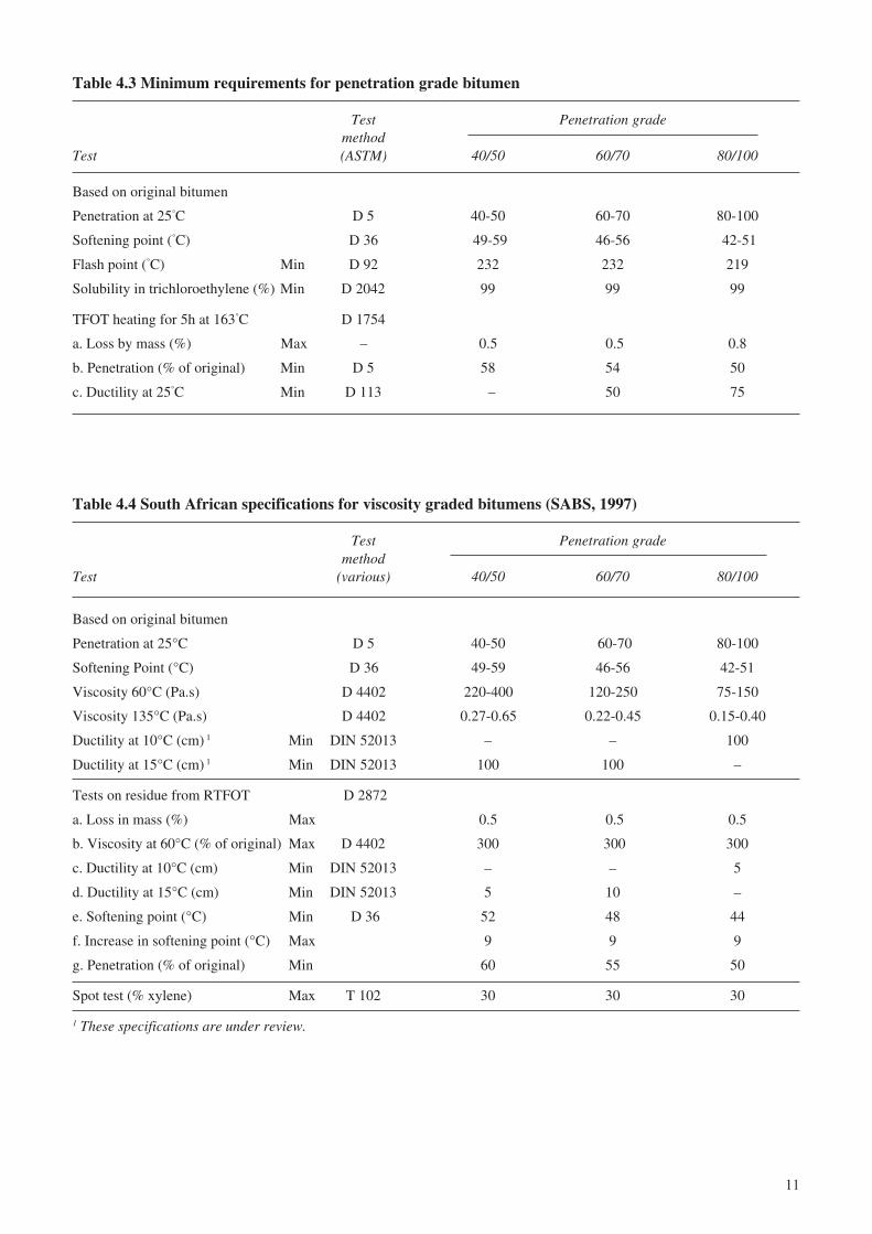
Requirements for penetration graded bitumens4.13 The basic requirements for penetration gradedbitumens are:
i Bitumen shall be prepared by the refining ofbitumen obtained from crude oil by suitablemethods. The bitumen shall be homogeneousand shall not foam when heated to 175°C.
ii The various grades of bitumen shall conform tothe requirements in Table 4.3.
8
Requirements for viscosity graded bitumens4.14 Authorities such as AASHTO, ASTM, theStandards Association of Australia (AS 2008, 1980)and the South African Bureau of Standards haveproduced specifications based on viscosity. TheAASHTO and ASTM tests use capillary viscometerswhilst the South African specifications utilise arotary viscometer which is ideal for acquiring data toplot on the Bitumen Test Data Chart. The SouthAfrica Bureau of Standard’s requirements forbitumen viscosity are shown in Table 4.4.
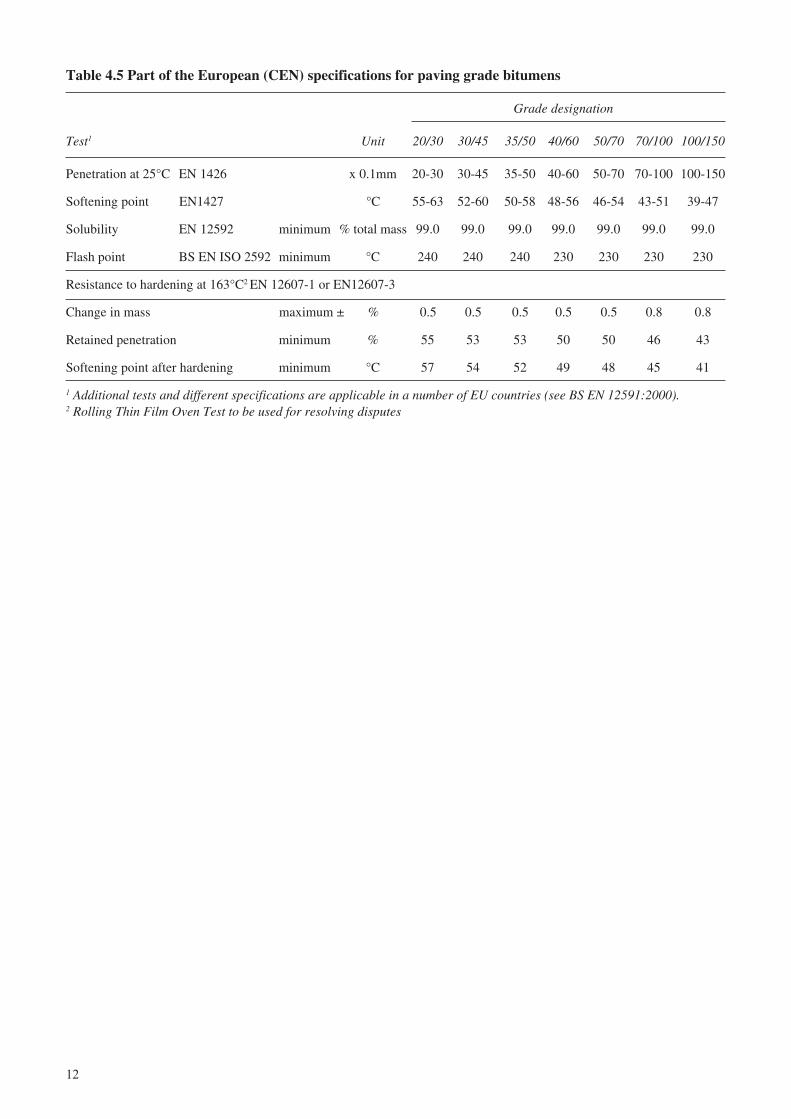
European specifications for paving grade bitumens4.15 The Comité Européen De Normalisation(CEN) has drawn up standards (EN 12591: 1999, orBS EN 12591:2000) for bitumen and bituminousbinders which are now used as national standards innineteen European countries. The CEN standardsinclude country-specific variations in specificationsand precision statements for test methods for bitumenand bituminous binders. The British Standard BS3690-1:1989 is now obsolete.
4.16 Specifications for grades most appropriate foruse in tropical countries have been selected from thestandards and reproduced in Table 4.5. In principle,specifications can be selected that are suitable for usein hot countries, however, it is essential thatauthorities refer to original CEN standards beforeadopting any of the recommendations.
Bitumen durability4.17 Bitumens derived from different sources ofcrude oil can have varying resistance to oxidation.Their characteristics can be further affected by thetype of refining plant in which they are produced.The main purpose of most oil refining is to obtain thevaluable distillates such as naphtha’s, fuel andheavier oils. After distillation, the bitumen residue isusually too soft to be used for paving and must betreated further. There are two methods of treatment.The first involves either air blowing (or oxidation) ofthe residue, typically carried out in fuel producingrefineries. The second is blending with propane-precipitated bitumen, which is a by-product of themanufacture of lubricating oil.
4.18 Depending upon the properties of the crude oiland the processing, bitumen produced in the propane-precipitation method can be more durable. This canbe determined by the extended RTFOT developed inAustralia (Dickinson, 1984). Financial restraints maymean that authorities must purchase bitumen at themost competitive open market prices. However, theimport of more durable bitumen should be seriouslyconsidered for major projects such as internationalairfields and important transcontinental routes.
9
Table 4.1 Required properties for HMA aggregates
Properties
Property Test Wearing course Binder course
Cleanliness Sand equivalent:1 for < 4.75mm fraction
<1.5 x 10⁶ esa >35
>1.5 x 10⁶ esa >40
(Material passing 0.425mm sieve)
Plasticity index2 <4
Linear shrinkage % <2
Particle shape Flakiness index3 <35
Strength Aggregate Crushing Value (ACV) 4 <25
Aggregate Impact Value (AIV) 4 <25
10% FACT (dry) kN 4 >160
Los Angeles Abrasion (LAA) 5 <30 <35
Abrasion Aggregate Abrasion Value (AAV) 4
250-1000 cv/lane/day <16 –
1000-2500 cv/lane/day <14 –
>2500 cv/lane/day <12 –
Polishing Polished Stone Value 4 (see Table 4.2) –
Water absorption Water absorption 6 <2
Soundness 7 Sodium Sulphate Test: Coarse <10(5 cycles, % loss) Fine <16
Magnesium Sulphate Test: Coarse <15Fine <20
Bitumen affinity Immersion Mechanical Test: Index of 8 >75retained Marshall stability
Static Immersion Test 9 >95% coating retained
Retained Indirect Tensile strength 10 >79% (at 7%VIM)
1 AASHTO T176 6 British Standard 812, Part 22 British Standard 1377: Part 2 7 AASHTO T1043 British Standard 812, Part 105 8 D Whiteoak (1990)4 British Standard 812, Parts 110 to 114 9 AASHTO T1825 ASTM C131 and C535 10 AASHTO T283
10
Table 4.2 Minimum PSV for coarse surfacing aggregates for roads in Britain
Traffic (cv1/l/d) at end of design life
0 101 251 501 751 1001 1251 1501 1751 2001 2251 2501 2751to to to to to to to to to to to to to Over
Site definition 100 250 500 750 1000 1250 1500 1750 2000 2250 2500 2750 3250 3250
1 Motorway (main line).
Dual carriageway(all purpose)
55 57 60 65 68non-event sections.
Dual carriageway(all purpose)minor junctions.
2 Single carriagewaynon-event sections.
45 50 53 55 57 60 63 65 68Single carriagewayminor junctions.
3 Approaches to andacross major junctions(all limbs).
Gradient 5%-10%,longer than 50m (Dualdownhill; single uphill 50 55 57 60 63 65 68 over 70and downhill).
Bend (not subject to64 kph or lower speedlimit) radius 100-250m.
Roundabout
4 Gradient >10%, longerthan 50m (Dualdownhill; single uphilland downhill).
55 60 63 65 68 over 70Bend (not subject to64 kph or lower speedlimit) radius <100m.
5 Approach to roundabout,traffic signals, pedestriancrossing, railway level 63 65 68 over 70
crossing, etc.
1Commercial vehicles are defined as those over 15 kN unladen weight
11
Table 4.3 Minimum requirements for penetration grade bitumen
Test Penetration grademethod
Test (ASTM) 40/50 60/70 80/100
Based on original bitumen
Penetration at 25°C D 5 40-50 60-70 80-100
Softening point (°C) D 36 49-59 46-56 42-51
Flash point (°C) Min D 92 232 232 219
Solubility in trichloroethylene (%) Min D 2042 99 99 99
TFOT heating for 5h at 163°C D 1754
a. Loss by mass (%) Max – 0.5 0.5 0.8
b. Penetration (% of original) Min D 5 58 54 50
c. Ductility at 25°C Min D 113 – 50 75
Table 4.4 South African specifications for viscosity graded bitumens (SABS, 1997)
Test Penetration grademethod
Test (various) 40/50 60/70 80/100
Based on original bitumen
Penetration at 25°C D 5 40-50 60-70 80-100
Softening Point (°C) D 36 49-59 46-56 42-51
Viscosity 60°C (Pa.s) D 4402 220-400 120-250 75-150
Viscosity 135°C (Pa.s) D 4402 0.27-0.65 0.22-0.45 0.15-0.40
Ductility at 10°C (cm) 1 Min DIN 52013 – – 100
Ductility at 15°C (cm) 1 Min DIN 52013 100 100 –
Tests on residue from RTFOT D 2872
a. Loss in mass (%) Max 0.5 0.5 0.5
b. Viscosity at 60°C (% of original) Max D 4402 300 300 300
c. Ductility at 10°C (cm) Min DIN 52013 – – 5
d. Ductility at 15°C (cm) Min DIN 52013 5 10 –
e. Softening point (°C) Min D 36 52 48 44
f. Increase in softening point (°C) Max 9 9 9
g. Penetration (% of original) Min 60 55 50
Spot test (% xylene) Max T 102 30 30 30
1 These specifications are under review.
12
Table 4.5 Part of the European (CEN) specifications for paving grade bitumens
Grade designation
Test1 Unit 20/30 30/45 35/50 40/60 50/70 70/100 100/150
Penetration at 25°C EN 1426 x 0.1mm 20-30 30-45 35-50 40-60 50-70 70-100 100-150
Softening point EN1427 °C 55-63 52-60 50-58 48-56 46-54 43-51 39-47
Solubility EN 12592 minimum % total mass 99.0 99.0 99.0 99.0 99.0 99.0 99.0
Flash point BS EN ISO 2592 minimum °C 240 240 240 230 230 230 230
Resistance to hardening at 163°C2 EN 12607-1 or EN12607-3
Change in mass maximum ± % 0.5 0.5 0.5 0.5 0.5 0.8 0.8
Retained penetration minimum % 55 53 53 50 50 46 43
Softening point after hardening minimum °C 57 54 52 49 48 45 41
1 Additional tests and different specifications are applicable in a number of EU countries (see BS EN 12591:2000).2 Rolling Thin Film Oven Test to be used for resolving disputes
13
5 Mix design for HMA
Introduction to mix design methods
5.1 Ideally the design of an HMA mix involves thefollowing iterative process:
i establishing candidate mixes with satisfactoryvolumetric composition;
ii testing to confirm that the compacted mix hasthe required properties for the expected traffic;and, if necessary,
iii adjusting the mix composition and re-test untilthe design requirements are satisfied.
5.2 Mix design for AC surfacing materials indeveloping countries is commonly based on therecommendations given in the Asphalt InstituteManual Series, MS-2 (1994) and is carried out usingthe Marshall test procedure. This method employsimpact compaction with the Marshall hammer toproduce briquettes of different compositions. Thebriquettes are then tested to ensure that the mixcriteria are appropriate for the design traffic. Anoutline of the method is given in Appendix C.
5.3 In MS-2, heavy traffic is defined as greater than1 million esa and 75 blow Marshall compaction isrecommended for the design of AC’s which areexpected to carry this amount of traffic. However, thebasic requirement of the method is that the level ofMarshall compaction used should produce a density inthe design mix which is equal to that which will beproduced in the road after secondary compaction undertraffic. Unfortunately there is no method fordetermining what this level of compaction should be,other than from empirical knowledge, and it istherefore common practice to use 75 blow compactionfor all design traffic loads in excess of 1 million esa.
5.4 The design traffic loading of 1 million esa isnow being exceeded by ever increasing margins andit was the need for a more comprehensive designmethod that led to development of the Superpave™
method of developed during the Strategic HighwayResearch Program (SHRP) in the USA. Superpave™
is a trademark of the Strategic Highway ResearchProgram.
5.5 The Superpave™ procedure involves carefulselection and detailed testing of bitumen (AsphaltInstitute Superpave Series No.1, 1997) and the use ofa gyratory compactor for mix design (AsphaltInstitute Superpave Series No.2, Third Edition,2001). Mix design requires that volumetricrequirements are met and that the design mix willhave compaction characteristics that are related to theexpected traffic loading. An outline of theSuperpave™ method is given in Appendix D.
5.6 AUSTROADS have developed a provisionalprocedure based on the use of a gyratory compactorand performance tests similar to those developed inthe UK, namely Dynamic Creep and ResilientModulus tests. Requirements are specified for threelevels of design traffic where heavy traffic is definedas more than 5 million esa.
5.7 An ‘Interim guidelines for the design of hot-mix asphalt in South Africa’ has been introduced,(The South African National Roads Agency, 2001).The importance of volumetric design and compactioncharacteristics are emphasised in the guide. Amodified Marshall procedure allows continuousmonitoring of mix density to ensure that the mix hasdesirable compaction characteristics. Gyratorycompaction is also used to confirm that satisfactoryVIM will be retained under heavy and very heavytraffic. Appropriate performance tests are used inplace of Marshall stability and flow tests. These testsinclude Indirect Tensile Strength and ResilientModulus (ASTM D4123), Dynamic creep, Four PointBending Beam test, and Mix Permeability amongstothers. Practitioners should refer to the document toobtain a complete understanding of the methodology.
5.8 Authorities in developing countries will oftenencounter difficulties with more complex testmethods, including the initial cost of establishingsuitable laboratories and the maintenance andcalibration of the equipment. The use of gyratorycompactors is to be encouraged but it is expected thatthe Marshall procedure will remain the principlemethod of mix design for AC mixes in manydeveloping countries for several years. Whilst the useof performance tests of the types described inAppendix E would be useful for the design of HMAfor heavy traffic, guidance is given in Chapter 6 on asimple procedure based on refusal density.
5.9 A typical example of the effect of differentlevels of Marshall compaction is given in Appendix F.A simple method of compaction to refusal density isdescribed in Appendix G as a method of ensuring theretention of a minimum VIM in HMA mixes used onsevere sites.
Volumetric design of HMA mixes
5.10 For convenience, mix components are blendedin proportion by mass and expressed as percentagesof the complete mix. However, the controlling factorin the design of mixes for all traffic levels is thevolume of each mix component.
5.11 The volumetric design of a compacted HMA isaffected by:
i the proportions of the different aggregates andfiller;
ii the specific gravity of the different materials;
14
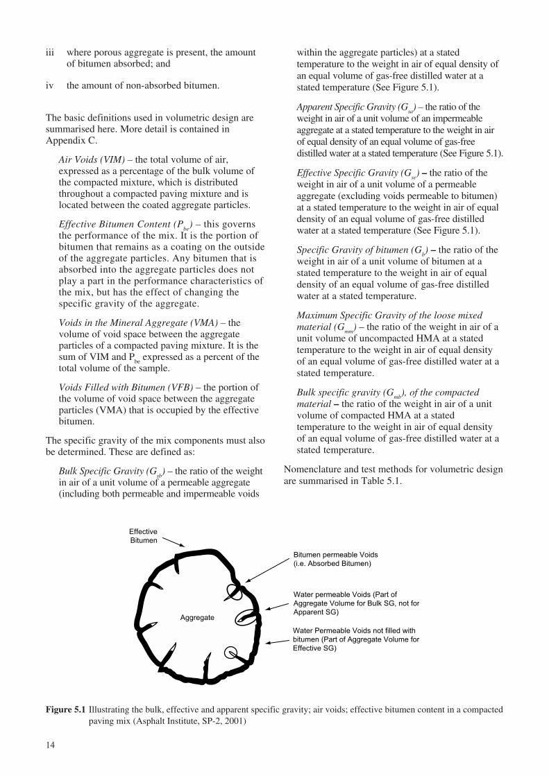
Figure 5.1 Illustrating the bulk, effective and apparent specific gravity; air voids; effective bitumen content in a compactedpaving mix (Asphalt Institute, SP-2, 2001)
Effective
Bitumen
Bitumen permeable Voids
(i.e. Absorbed Bitumen)
Water permeable Voids (Part of
Aggregate Volume for Bulk SG, not for
Apparent SG)
Water Permeable Voids not filled with
bitumen (Part of Aggregate Volume for
Effective SG)
Aggregate
iii where porous aggregate is present, the amountof bitumen absorbed; and
iv the amount of non-absorbed bitumen.
The basic definitions used in volumetric design aresummarised here. More detail is contained inAppendix C.
Air Voids (VIM) – the total volume of air,expressed as a percentage of the bulk volume ofthe compacted mixture, which is distributedthroughout a compacted paving mixture and islocated between the coated aggregate particles.
Effective Bitumen Content (Pbe
) – this governsthe performance of the mix. It is the portion ofbitumen that remains as a coating on the outsideof the aggregate particles. Any bitumen that isabsorbed into the aggregate particles does notplay a part in the performance characteristics ofthe mix, but has the effect of changing thespecific gravity of the aggregate.
Voids in the Mineral Aggregate (VMA) – thevolume of void space between the aggregateparticles of a compacted paving mixture. It is thesum of VIM and P
be expressed as a percent of the
total volume of the sample.
Voids Filled with Bitumen (VFB) – the portion ofthe volume of void space between the aggregateparticles (VMA) that is occupied by the effectivebitumen.
The specific gravity of the mix components must alsobe determined. These are defined as:
Bulk Specific Gravity (Gsb
) – the ratio of the weightin air of a unit volume of a permeable aggregate(including both permeable and impermeable voids
within the aggregate particles) at a statedtemperature to the weight in air of equal density ofan equal volume of gas-free distilled water at astated temperature (See Figure 5.1).
Apparent Specific Gravity (Gsa) – the ratio of the
weight in air of a unit volume of an impermeableaggregate at a stated temperature to the weight in airof equal density of an equal volume of gas-freedistilled water at a stated temperature (See Figure 5.1).
Effective Specific Gravity (Gse) – the ratio of the
weight in air of a unit volume of a permeableaggregate (excluding voids permeable to bitumen)at a stated temperature to the weight in air of equaldensity of an equal volume of gas-free distilledwater at a stated temperature (See Figure 5.1).
Specific Gravity of bitumen (Gb) – the ratio of the
weight in air of a unit volume of bitumen at astated temperature to the weight in air of equaldensity of an equal volume of gas-free distilledwater at a stated temperature.
Maximum Specific Gravity of the loose mixedmaterial (G
mm) – the ratio of the weight in air of a
unit volume of uncompacted HMA at a statedtemperature to the weight in air of equal densityof an equal volume of gas-free distilled water at astated temperature.
Bulk specific gravity (Gmb
), of the compactedmaterial – the ratio of the weight in air of a unitvolume of compacted HMA at a statedtemperature to the weight in air of equal densityof an equal volume of gas-free distilled water at astated temperature.
Nomenclature and test methods for volumetric designare summarised in Table 5.1.
15
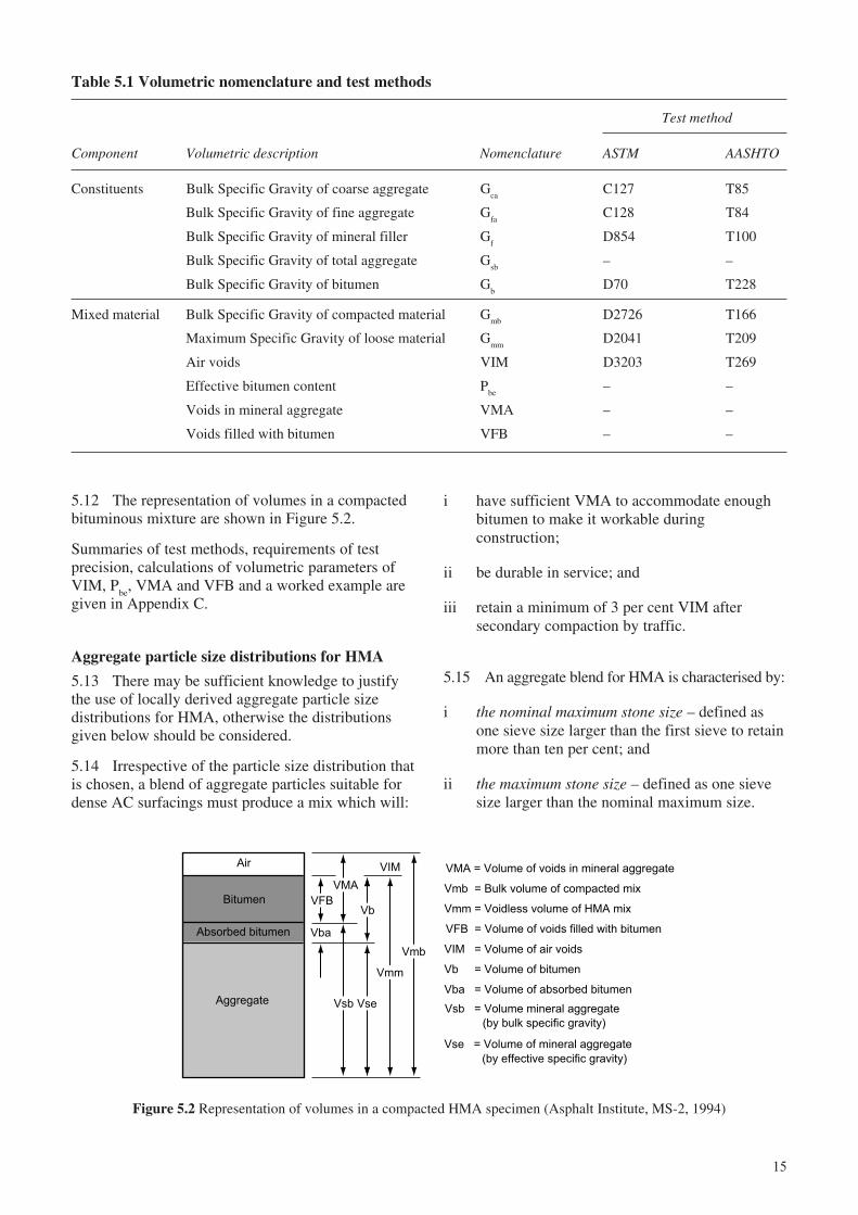
Table 5.1 Volumetric nomenclature and test methods
Test method
Component Volumetric description Nomenclature ASTM AASHTO
Constituents Bulk Specific Gravity of coarse aggregate Gca
C127 T85
Bulk Specific Gravity of fine aggregate Gfa
C128 T84
Bulk Specific Gravity of mineral filler Gf
D854 T100
Bulk Specific Gravity of total aggregate Gsb
– –
Bulk Specific Gravity of bitumen Gb
D70 T228
Mixed material Bulk Specific Gravity of compacted material Gmb
D2726 T166
Maximum Specific Gravity of loose material Gmm
D2041 T209
Air voids VIM D3203 T269
Effective bitumen content Pbe
– –
Voids in mineral aggregate VMA – –
Voids filled with bitumen VFB – –
Figure 5.2 Representation of volumes in a compacted HMA specimen (Asphalt Institute, MS-2, 1994)
Bitumen
Absorbed bitumen
Aggregate
Air
Vmb
Vba
VIM VMA = Volume of voids in mineral aggregate
Vmb = Bulk volume of compacted mix
Vmm = Voidless volume of HMA mix
VFB = Volume of voids filled with bitumen
VIM = Volume of air voids
Vb = Volume of bitumen
Vba = Volume of absorbed bitumen
Vsb = Volume mineral aggregate
(by bulk specific gravity)
Vse = Volume of mineral aggregate
(by effective specific gravity)
Vmm
VseVsb
VFB
VMA
Vb
5.12 The representation of volumes in a compactedbituminous mixture are shown in Figure 5.2.
Summaries of test methods, requirements of testprecision, calculations of volumetric parameters ofVIM, P
be, VMA and VFB and a worked example are
given in Appendix C.
Aggregate particle size distributions for HMA
5.13 There may be sufficient knowledge to justifythe use of locally derived aggregate particle sizedistributions for HMA, otherwise the distributionsgiven below should be considered.
5.14 Irrespective of the particle size distribution thatis chosen, a blend of aggregate particles suitable fordense AC surfacings must produce a mix which will:
i have sufficient VMA to accommodate enoughbitumen to make it workable duringconstruction;
ii be durable in service; and
iii retain a minimum of 3 per cent VIM aftersecondary compaction by traffic.
5.15 An aggregate blend for HMA is characterised by:
i the nominal maximum stone size – defined asone sieve size larger than the first sieve to retainmore than ten per cent; and
ii the maximum stone size – defined as one sievesize larger than the nominal maximum size.
16
The nominal maximum stone size determines theminimum VMA required in the aggregate blend. Themaximum stone size that can be used in a mix isgoverned by the proposed thickness of the HMA layer.
5.16 To achieve good compaction the layerthickness will normally have to be between twice themaximum stone size for fine mixes and four timesthe maximum stone size for mixes with a highcontent of coarse aggregates. Mixes normallyrecommended for severe traffic loading, or which fallbelow the Superpave™ restricted zone, would be inthe latter category.
Particle size distributions for AC wearing courses5.17 Authorities will often base the choice ofparticle size distribution on local experience, or therecommendations of the Asphalt Institute (SS-1, orMS-2, Table 2.1, 1994). Particle size distributionsrecommended by the Asphalt Institute for wearingcourse layers are shown in Table 5.2.
minimises VMA and produces a mix which will bevery sensitive to proportioning errors. It is bestpractice to modify the distribution away from themaximum density line.
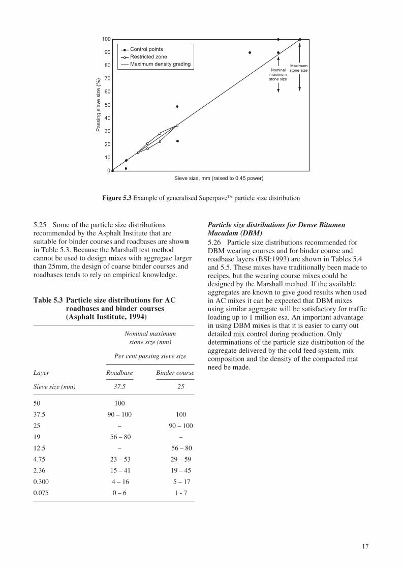
5.20 The Superpave™ mix design procedureaddresses the need for sufficient VMA by specifyingcontrol points within which the particle sizedistribution must fit and a restricted zone. VMA isincreased both by displacing the particle sizedistribution away from the maximum density line andby avoiding the restricted zone. An example of ageneralised aggregate grading chart showing controlpoints and the restricted zone is shown in Figure 5.3.The maximum density grading is shown as a straightline where the sieve sizes on the x-axis have beenraised to the power 0.45.
5.21 Use of the restricted zone is not compulsory. Itwas originally specified to limit the amount ofnatural rounded sand that could be used in a blend. Amix containing only fully crushed rock fines andhaving a particle size distribution which passesthrough the restricted zone may develop goodparticle interlock and sufficient VMA. It isrecommended, therefore, that the restricted zone isnot adopted as an essential requirement of localspecifications, rather that it is an option for heavilytrafficked roads.
5.22 The combined effect of VMA selection andparticle size distribution becomes more sensitive astraffic loading increases, particularly under the severeconditions which apply in many developingcountries. Particle size distributions which passbelow the restricted zone will normally provide themost effective material for roads carrying very heavytraffic and for severe sites, but this must beconfirmed by adequate laboratory testing. It ispossible that adjustment of the proportions of largersized aggregates will produce an equivalent increasein VMA as adjusting the particle size distribution topass outside the restricted zone.
5.23 The specified control points and restrictedzones for HMA wearing course mixes depend on thenominal maximum stone size. Superpave™ particlesize distributions and an example of a complete chartis given in Appendix D.
Particle size distributions for AC binder courses androadbases5.24 The Asphalt Institute MS-2 (1994) andSuperpave™ (2001) do not describe particle sizedistributions specifically for binder courses androadbases. In practice, asphalt surfacings thicker thanabout 70mm are laid as two layers and the relationshipbetween the thickness of a layer and the maximumstone size largely determines the particle sizedistribution that will be used (see paragraph 5.16).
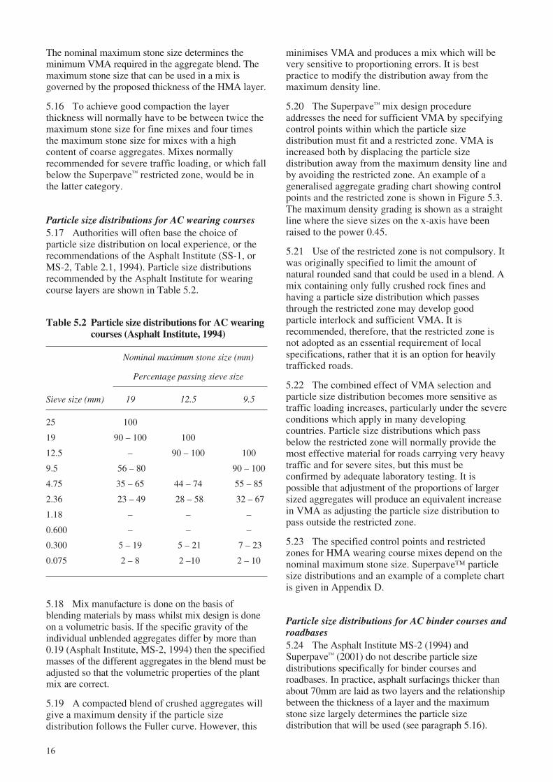
Table 5.2 Particle size distributions for AC wearingcourses (Asphalt Institute, 1994)
Nominal maximum stone size (mm)
Percentage passing sieve size
Sieve size (mm) 19 12.5 9.5
25 100
19 90 – 100 100
12.5 – 90 – 100 100
9.5 56 – 80 90 – 100
4.75 35 – 65 44 – 74 55 – 85
2.36 23 – 49 28 – 58 32 – 67
1.18 – – –
0.600 – – –
0.300 5 – 19 5 – 21 7 – 23
0.075 2 – 8 2 –10 2 – 10
5.18 Mix manufacture is done on the basis ofblending materials by mass whilst mix design is doneon a volumetric basis. If the specific gravity of theindividual unblended aggregates differ by more than0.19 (Asphalt Institute, MS-2, 1994) then the specifiedmasses of the different aggregates in the blend must beadjusted so that the volumetric properties of the plantmix are correct.
5.19 A compacted blend of crushed aggregates willgive a maximum density if the particle sizedistribution follows the Fuller curve. However, this
17
Figure 5.3 Example of generalised Superpave™ particle size distribution
5.25 Some of the particle size distributionsrecommended by the Asphalt Institute that aresuitable for binder courses and roadbases are shownin Table 5.3. Because the Marshall test methodcannot be used to design mixes with aggregate largerthan 25mm, the design of coarse binder courses androadbases tends to rely on empirical knowledge.
Particle size distributions for Dense BitumenMacadam (DBM)5.26 Particle size distributions recommended forDBM wearing courses and for binder course androadbase layers (BSI:1993) are shown in Tables 5.4and 5.5. These mixes have traditionally been made torecipes, but the wearing course mixes could bedesigned by the Marshall method. If the availableaggregates are known to give good results when usedin AC mixes it can be expected that DBM mixesusing similar aggregate will be satisfactory for trafficloading up to 1 million esa. An important advantagein using DBM mixes is that it is easier to carry outdetailed mix control during production. Onlydeterminations of the particle size distribution of theaggregate delivered by the cold feed system, mixcomposition and the density of the compacted matneed be made.
0
10
20
30
40
50
60
70
80
90
100
Sieve size, mm (raised to 0.45 power)
Pa
ssin
g s
ieve
siz
e (
%)
Control points
Restricted zone
Maximum density grading Maximumstone sizeNominal
maximumstone size
Table 5.3 Particle size distributions for ACroadbases and binder courses(Asphalt Institute, 1994)
Nominal maximumstone size (mm)
Per cent passing sieve size
Layer Roadbase Binder course
Sieve size (mm) 37.5 25
50 100
37.5 90 – 100 100
25 – 90 – 100
19 56 – 80 –
12.5 – 56 – 80
4.75 23 – 53 29 – 59
2.36 15 – 41 19 – 45
0.300 4 – 16 5 – 17
0.075 0 – 6 1 - 7
18
Table 5.5 Particle size distributions for DBMbinder course and roadbase layers
UK nomenclature for size (mm)
Percentage passing sieve size
Binder course Roadbase
Sieve size (mm) 20 40 28
50 – 100 –
37.5 – 95 – 100 100
28 100 70 – 94 90 – 100
20 95 – 100 – 71 – 95
14 65 – 85 56 – 76 58 – 82
10 52 – 72 – –
6.3 39 – 55 44 – 60 44 – 60
3.35 32 – 46 32 – 46 32 – 46
0.300 7 – 21 7 – 21 7 – 21
0.075 2 – 9 2 – 9 2 – 9
Typical bitumen 4.7 3.5 4.0content (%)
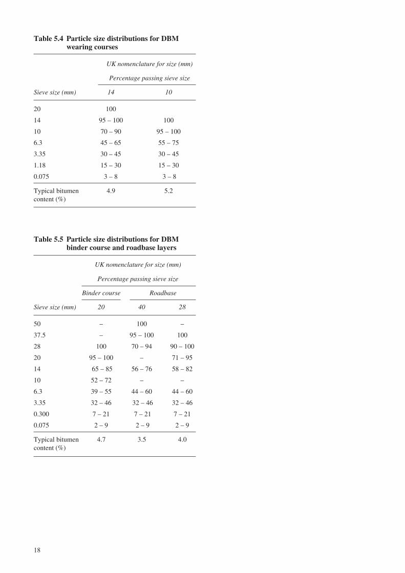
Table 5.4 Particle size distributions for DBMwearing courses
UK nomenclature for size (mm)
Percentage passing sieve size
Sieve size (mm) 14 10
20 100
14 95 – 100 100
10 70 – 90 95 – 100
6.3 45 – 65 55 – 75
3.35 30 – 45 30 – 45
1.18 15 – 30 15 – 30
0.075 3 – 8 3 – 8
Typical bitumen 4.9 5.2content (%)
19
6 Mix design specifications
Mix design for continuously graded wearing courses
6.1 AC wearing courses tend to be sensitive tovariations in composition. A high level of qualitycontrol is essential during laboratory design,manufacture, compliance testing and construction.The small range of VIM values shown in Table 6.1and the effect they have on mix performanceillustrates this sensitivity.
not be able to determine absolute values for surfacearea and will rely on determinations of VMA.
6.4 Unfortunately the measurement of VMA issubject to large variability (Hinrichsen and Heggen,1996) with typical standard deviations of 1.3 percent. This is a large value in comparison to theincremental steps given in normal specifications (seeTable 6.2). In addition, two particle size distributionshaving different maximum sized aggregate mayoverlap to a considerable degree and the difference inaggregate surface area may not be sufficiently largeto warrant a large change in the specified VMA.
6.5 It is recommended that bitumen film thickness(i.e. the nominal thickness of non-absorbed bitumencoating the aggregate particles) is calculated, asshown in Appendix C, and used to assist in the designprocess. If the bitumen film thickness is less than 7microns it is recommended that the determination ofVMA be reviewed. Finally, evidence from fieldcompaction trials, including the volumetric propertiesof cores cut from the trials, will help to confirm thatthe mix is sufficiently workable and that specifiedproperties are obtained.
6.6 It is recommended that AC mix design usingthe Marshall method be based on three categories ofdesign traffic:
i < 5 million esa;
ii > 5 million esa; and
iii severe sites - defined as climbing lanes andjunctions that are subject to slow moving heavytraffic.
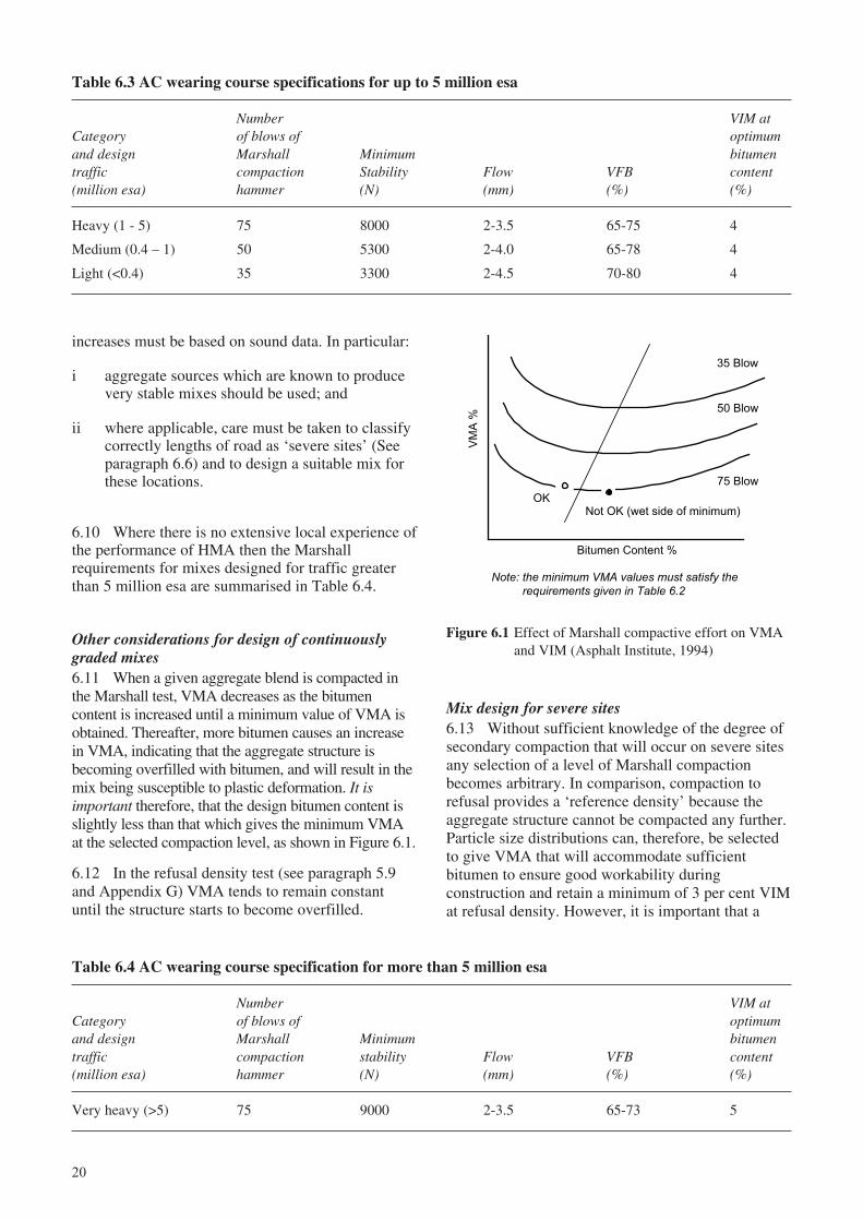
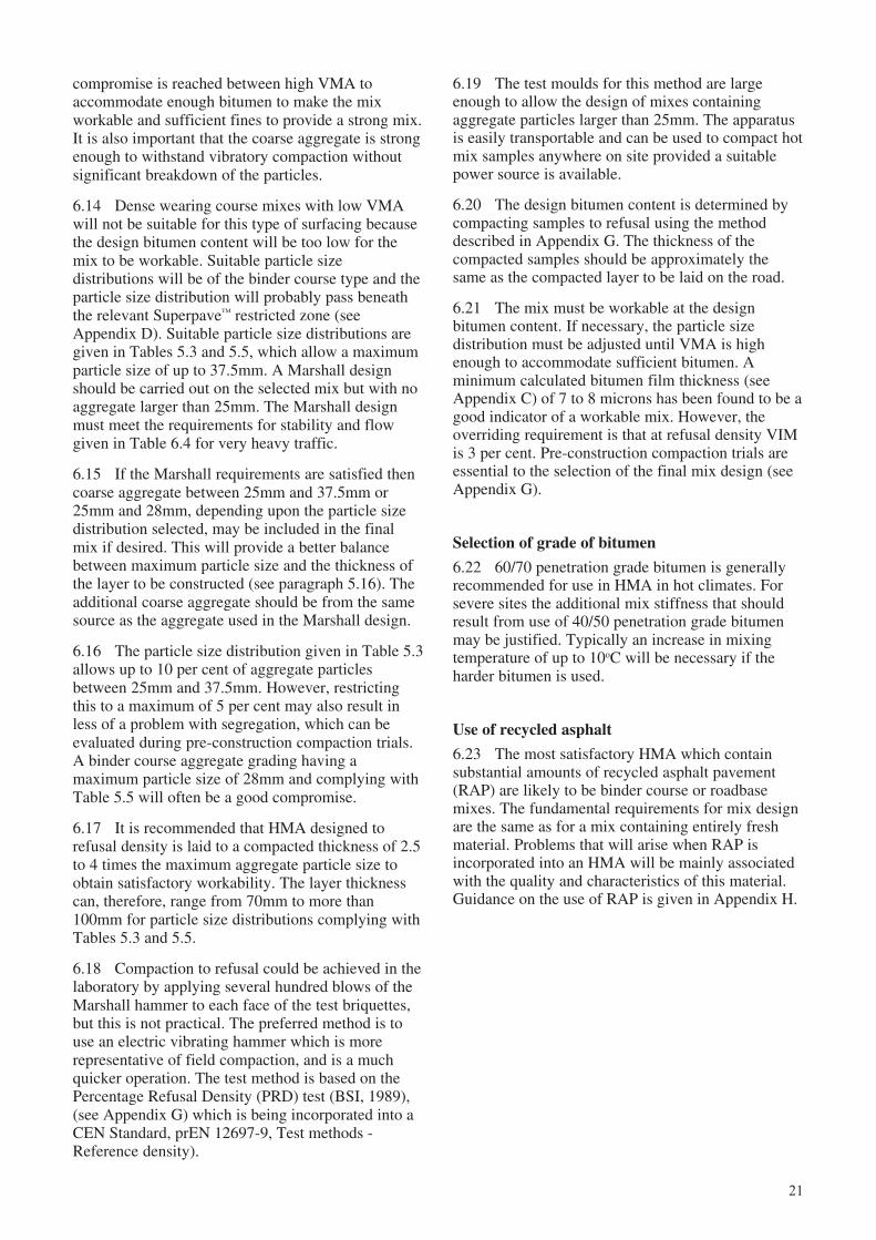
For design traffic less than 5 million esa6.7 In principle, any of the wearing course or bindercourse gradings described in Chapter 5 can be used as arunning surface for traffic loading up to 5 million esa.The larger stone mixes have to be placed in thickerlayers and the surface finish of such mixes would have acoarser texture. All mixes should be designed to theAsphalt Institute (MS-2, 1994) Marshall criteria forwearing courses shown in Table 6.3. It will be notedthat a single value of 4 per cent VIM at the optimumbitumen content is recommended.
6.8 Some variation in mix composition is to beexpected during plant manufacture and MS-2recommends that variations in bitumen content shouldbe restricted to produce a variation in VIM of only 4 ±0.5 per cent at the design level of Marshall compaction.
For design traffic greater than 5 million esa6.9 Local experience may justify the use of similardesign criteria to those shown in Table 6.3 for designtraffic greater than 5 million esa. However, such
Table 6.1 Critical values of VIM in a wearingcourse
VIM(per cent) Effect
>5 Increasingly permeable to air and prone tooxidation of bitumen.
4 or 5 Target for design.
3-5 For a durable and stable mix.
<3 Prone to plastic deformation under heavyloading.
6.2 In order to achieve a balance of mix propertiesit is important that the aggregate structure of anHMA has sufficient VMA. The minimum VMArequired is related to the nominal stone size as shownin Table 6.2.
VMA and bitumen film thickness6.3 Whilst VMA is crucial to the correctvolumetric design of HMA it is important to beaware of the possible limitations in rigidly specifyingvalues and also of the difficulties in accuratelymeasuring VMA. The variation in bitumen contentwith change in maximum stone size should actuallybe related to the surface area of all of the aggregateparticles in an HMA. However, most authorities will
Table 6.2 Minimum VMA specified for AC mixes
Minimum VMA (per cent)@ Design VIM (per cent)
Nominal maximumstone size (mm) 4.0 5.0
37.5 11.0 12.0
25 12.0 13.0
19 13.0 14.0
12.5 14.0 15.0
9.5 15.0 16.0
20
Table 6.3 AC wearing course specifications for up to 5 million esa
Number VIM atCategory of blows of optimumand design Marshall Minimum bitumentraffic compaction Stability Flow VFB content(million esa) hammer (N) (mm) (%) (%)
Heavy (1 - 5) 75 8000 2-3.5 65-75 4
Medium (0.4 – 1) 50 5300 2-4.0 65-78 4
Light (<0.4) 35 3300 2-4.5 70-80 4
Table 6.4 AC wearing course specification for more than 5 million esa
Number VIM atCategory of blows of optimumand design Marshall Minimum bitumentraffic compaction stability Flow VFB content(million esa) hammer (N) (mm) (%) (%)
Very heavy (>5) 75 9000 2-3.5 65-73 5
Note: the minimum VMA values must satisfy the
requirements given in Table 6.2
OKNot OK (wet side of minimum)
35 Blow
50 Blow
75 BlowV
MA
%
Bitumen Content %
Figure 6.1 Effect of Marshall compactive effort on VMAand VIM (Asphalt Institute, 1994)
increases must be based on sound data. In particular:
i aggregate sources which are known to producevery stable mixes should be used; and
ii where applicable, care must be taken to classifycorrectly lengths of road as ‘severe sites’ (Seeparagraph 6.6) and to design a suitable mix forthese locations.
6.10 Where there is no extensive local experience ofthe performance of HMA then the Marshallrequirements for mixes designed for traffic greaterthan 5 million esa are summarised in Table 6.4.
Other considerations for design of continuouslygraded mixes6.11 When a given aggregate blend is compacted inthe Marshall test, VMA decreases as the bitumencontent is increased until a minimum value of VMA isobtained. Thereafter, more bitumen causes an increasein VMA, indicating that the aggregate structure isbecoming overfilled with bitumen, and will result in themix being susceptible to plastic deformation. It isimportant therefore, that the design bitumen content isslightly less than that which gives the minimum VMAat the selected compaction level, as shown in Figure 6.1.
6.12 In the refusal density test (see paragraph 5.9and Appendix G) VMA tends to remain constantuntil the structure starts to become overfilled.
Mix design for severe sites6.13 Without sufficient knowledge of the degree ofsecondary compaction that will occur on severe sitesany selection of a level of Marshall compactionbecomes arbitrary. In comparison, compaction torefusal provides a ‘reference density’ because theaggregate structure cannot be compacted any further.Particle size distributions can, therefore, be selectedto give VMA that will accommodate sufficientbitumen to ensure good workability duringconstruction and retain a minimum of 3 per cent VIMat refusal density. However, it is important that a
21
compromise is reached between high VMA toaccommodate enough bitumen to make the mixworkable and sufficient fines to provide a strong mix.It is also important that the coarse aggregate is strongenough to withstand vibratory compaction withoutsignificant breakdown of the particles.
6.14 Dense wearing course mixes with low VMAwill not be suitable for this type of surfacing becausethe design bitumen content will be too low for themix to be workable. Suitable particle sizedistributions will be of the binder course type and theparticle size distribution will probably pass beneaththe relevant Superpave™ restricted zone (seeAppendix D). Suitable particle size distributions aregiven in Tables 5.3 and 5.5, which allow a maximumparticle size of up to 37.5mm. A Marshall designshould be carried out on the selected mix but with noaggregate larger than 25mm. The Marshall designmust meet the requirements for stability and flowgiven in Table 6.4 for very heavy traffic.
6.15 If the Marshall requirements are satisfied thencoarse aggregate between 25mm and 37.5mm or25mm and 28mm, depending upon the particle sizedistribution selected, may be included in the finalmix if desired. This will provide a better balancebetween maximum particle size and the thickness ofthe layer to be constructed (see paragraph 5.16). Theadditional coarse aggregate should be from the samesource as the aggregate used in the Marshall design.
6.16 The particle size distribution given in Table 5.3allows up to 10 per cent of aggregate particlesbetween 25mm and 37.5mm. However, restrictingthis to a maximum of 5 per cent may also result inless of a problem with segregation, which can beevaluated during pre-construction compaction trials.A binder course aggregate grading having amaximum particle size of 28mm and complying withTable 5.5 will often be a good compromise.
6.17 It is recommended that HMA designed torefusal density is laid to a compacted thickness of 2.5to 4 times the maximum aggregate particle size toobtain satisfactory workability. The layer thicknesscan, therefore, range from 70mm to more than100mm for particle size distributions complying withTables 5.3 and 5.5.
6.18 Compaction to refusal could be achieved in thelaboratory by applying several hundred blows of theMarshall hammer to each face of the test briquettes,but this is not practical. The preferred method is touse an electric vibrating hammer which is morerepresentative of field compaction, and is a muchquicker operation. The test method is based on thePercentage Refusal Density (PRD) test (BSI, 1989),(see Appendix G) which is being incorporated into aCEN Standard, prEN 12697-9, Test methods -Reference density).
6.19 The test moulds for this method are largeenough to allow the design of mixes containingaggregate particles larger than 25mm. The apparatusis easily transportable and can be used to compact hotmix samples anywhere on site provided a suitablepower source is available.
6.20 The design bitumen content is determined bycompacting samples to refusal using the methoddescribed in Appendix G. The thickness of thecompacted samples should be approximately thesame as the compacted layer to be laid on the road.
6.21 The mix must be workable at the designbitumen content. If necessary, the particle sizedistribution must be adjusted until VMA is highenough to accommodate sufficient bitumen. Aminimum calculated bitumen film thickness (seeAppendix C) of 7 to 8 microns has been found to be agood indicator of a workable mix. However, theoverriding requirement is that at refusal density VIMis 3 per cent. Pre-construction compaction trials areessential to the selection of the final mix design (seeAppendix G).
Selection of grade of bitumen
6.22 60/70 penetration grade bitumen is generallyrecommended for use in HMA in hot climates. Forsevere sites the additional mix stiffness that shouldresult from use of 40/50 penetration grade bitumenmay be justified. Typically an increase in mixingtemperature of up to 10oC will be necessary if theharder bitumen is used.
Use of recycled asphalt
6.23 The most satisfactory HMA which containsubstantial amounts of recycled asphalt pavement(RAP) are likely to be binder course or roadbasemixes. The fundamental requirements for mix designare the same as for a mix containing entirely freshmaterial. Problems that will arise when RAP isincorporated into an HMA will be mainly associatedwith the quality and characteristics of this material.Guidance on the use of RAP is given in Appendix H.
22
Table 7.1 Tolerances for the manufacture of AC
Tolerances for mix constituents
Bitumen content (%)Permitted
Passing sieve range Wearing Bindersize (mm) (%) course course
>12.5 ±8
9.5 ±7
4.75 ±7 ±0.3 ±0.5
2.36 ±6
300 microns ±5
75 microns ±3
7 Mix production
General requirements
7.1 Initial HMA design is often carried out toenable suitable aggregates to be selected before theyare stockpiled for full-scale production. Stockpilingand calibration of the aggregate cold feed bins is thencompleted before a new mix design is made, usingaggregate which has passed through the fully-operating asphalt plant.
7.2 The following are some of the factors that areimportant to the production of a consistent mix ofgood quality:
i building stockpiles with uniform distributions ofaggregate sizes;
ii calibration of plant weigh scales;
iii calibration of gate settings on aggregate coldfeed bins; and
iv correct adjustment of dust extraction equipment.
7.3 Having confirmed that a suitable laboratorydesign mix, which can be called the ‘preliminary jobmix formula’, can be produced using the availableaggregate sources, stockpiles of each material arethen built. The quality and consistency of thestockpiled materials must be carefully monitored andthe stockpiles constructed so as to minimisesegregation. ‘Dry’ runs of aggregates are required toadjust cold bin vibrators and to calibrate gatesettings. The rate of flow of sand-sized fines throughthe gate of a cold bin can be seriously affected if themoisture content of the material changes. Stockpilesof fine materials may therefore need to be covered toprevent frequent changes in flow characteristics. Theuse of efficient, variable-control, vibration devices onthe cold feed bins to maintain steady flows ofmaterials is important. Even then fines may still‘bridge’ in the cold feed bin and it will be necessaryto manually break down the material to maintain asteady rate of flow.
7.4 It may be found that fines collected through theplant’s cyclone system do not have desirableproperties, or are in excess of requirements. Alsocement or hydrated lime may be required as an anti-stripping agent and the natural filler content mayhave to be reduced to allow for this. Thus for theproduction of good quality AC wearing coursematerial it is important to have a separate filler feedand weighing system on batch plants so that thevolumes of these materials can be controlled.
7.5 Once the settings for the cold aggregate feedhave been made to produce the required blend, thematerial should be run through the fully-operating
asphalt plant without the addition of bitumen. Mixdesign is then repeated using the plant-run aggregateand added filler where this is appropriate. Ifnecessary, adjustments are made until a suitable mixdesign is produced. This mix is likely to be slightlydifferent to the preliminary job mix formula and canbe called the ‘trial job mix formula’.
7.6 Trial mixes are then made in the asphalt plantwith the addition of bitumen and filler in the pre-determined proportions. This plant mix must be testedto ensure that volumetric and Marshall designrequirements are satisfied. If necessary, furtheradjustments to the mix proportions should be made and,in exceptional cases, the need to obtain differentaggregates must be considered if the required mixspecifications cannot be met with the existing materials.
7.7 Having established a plant mix design (it canbe called the ‘job mix formula’) tolerances must beapplied to the composition of the plant producedHMA. It is important that the required Marshall andvolumetric criteria are met over the range ofpermitted tolerances. The control of variations in mixcomposition with respect to design criteria arediscussed in Appendix C and typical plant mixtolerances are summarised in Table 7.1.
7.8 The tolerances for the aggregate grading arefor a single test result and are applied to the job mixformula to establish a particle size distributionenvelope with which the plant mix must conform. Itis expected that the new envelope will runapproximately parallel with the boundaries of theoriginal envelope, but it may overlap it.
7.9 As explained in paragraph 6.8 the tolerance onbitumen content should be reconciled with the veryimportant recommendation that VIM at the designlevel of compaction should be within ± 0.5 per centof the target value of either 4 or 5 per cent.
23
7.10 After a plant mix design is established, full-scale compaction trials must be carried out toconfirm that the mix is workable and to determine theoptimum use of rollers to achieve the required fielddensities.
Aggregate stock piles and cold feeds
7.11 The importance of good stockpile managementand control of cold bin settings cannot be overstated.The quality and consistency of the HMA produced inthe plant will be controlled by the uniformity of thestockpiled materials and by their correct proportioningfrom the aggregate cold bins, even for batch plantswith separate aggregate hot bins. This is because a5mm screen is often the smallest size used in theseplants and AC wearing course mixes may contain 50per cent of material finer than 5mm. Where these finescome from multiple sources such as crushed rockfines, natural sand and material adhering to the largeraggregate particles, it will only be possible to controlthe proportioning at the cold feed.
7.12 Once a plant mix specification has beenestablished and production is started it is importantthat new materials for stockpiling are testedfrequently to confirm that no significant changes inaggregate properties are occurring. It is advisable tocreate new stockpiles, rather than add to those whichhave been tested and are in use. If the properties ofnew aggregates cause the plant mix to fall outside ofagreed specifications, and where this cannot easily becorrected, then a new mix design and plant-mixverification tests must be carried out.
7.13 Representative samples of the daily plant mixproduction and of stockpiled material must be takento confirm compliance with all mix specifications.Advice on sampling frequency can be obtained fromthe Asphalt Institute Manual, MS-22 (AsphaltInstitute, 2000).
24
Table 8.1 HMA mixing temperatures
Bitumen penetration Typical mixinggrade temperature °C
80/100 130-165
60/70 140-170
40/50 150-180
8 Construction of asphalt surfacings
8.1 The purpose of this Chapter is to highlightsome of the important aspects of construction ofHMA surfacings. The Asphalt Institute Manual, MS-22 (Asphalt Institute, 2000) describes the principlesof constructing hot mix asphalt pavements and thereader is encouraged to refer to this, or otherpublications (e.g. Hunter, 1994), if comprehensivedetail of construction methods is required.
Mixing and compaction
8.2 Close control of mixing temperature isessential. In order to minimise the hardening of thebitumen, the lowest temperature commensurate withgood coating of the aggregate and compactionrequirements should be used and temperaturevariations should be minimised. This also makes iteasier to obtain uniform compaction and to meettarget densities.
8.3 Typical mixing temperatures are summarisedin Table 8.1 for guidance. Where possible theviscosity of the bitumen should be measured over arange of temperatures and plotted on the BitumenTest Data Chart (see Appendix B) so that the idealmixing temperature, at which the viscosity of thebitumen is between approximately 0.2 and 0.5 Pa.s,can then be read from the chart.
are carried out to determine the best combination ofrollers, numbers of passes and any limitations whichmust be applied to rolling temperatures.
8.6 Vibrating rollers can cause considerabledamage to an HMA layer if they are used incorrectly.For example, a vibrating roller operated at highforward speed with high amplitude compaction willleave a series of ridges in the mat. The optimumsettings for the frequency and amplitude of vibrationfor the vibrating roller and the temperature rangeover which it can effectively be used for compactionmust be determined.
8.7 In some cases it will be found that dead-weightrollers and pneumatic-tyred rollers are effective forcompleting the bulk of the compaction work, but avibrating roller may be needed to ensure that thedesired level of compaction is achieved. As few as 2to 4 passes of a vibrating roller can be effective whenused at the appropriate compaction temperature.
VIM after construction
AC mixes designed by the Marshall method8.8 Control of compaction during construction isachieved by expressing in situ core densities relativeto the density of plant mixed material compacted inthe laboratory. The same number of blows of theMarshall hammer are applied to the plant mix aswere used for the original laboratory mix design.Typically, the minimum level of relative compactionspecified is 96 per cent.
8.9 Because an AC surfacing mix is designed tohave 4 per cent VIM at the appropriate level oflaboratory compaction, a relative density of 96 percent will give in situ VIM of approximately 8 percent (or 9 per cent if the design VIM is 5 per cent).
8.10 With VIM of more than 8 per cent thesurfacing will be vulnerable to prematuredeterioration through ageing of the bitumen.Improved durability would be obtained byspecifying a higher level of compaction, however,it is often difficult to consistently achieve relativecompaction as high as 98 per cent and it istherefore recommended that the specified level offield compaction should be 97 per cent oflaboratory density.
8.11 Where traffic is channelled only limitedcompaction will take place on areas outside thewheelpaths. This may result in the need for earlymaintenance if damage resulting from ‘top-down’cracking is to be prevented. In any event the surfaceshould be sealed when cracking develops and wellbefore cracks penetrate to the full depth of thesurfacing.
8.4 Thorough compaction during construction isvital because traffic is likely to give very littleadditional compaction outside of the wheelpaths. Asthe demand grows for HMA surfacings to carry higherdesign traffic loads, so the need for mixes to havehigher resistance to rutting increases. This in turndemands higher compactive effort during construction.
8.5 Dead-weight steel rollers are effective and areessential for finishing joints between adjacent lanesand at the start of each laying operation. Pneumatic-tyred rollers are effective at compacting the lower partof thicker layers but, for high capacity roads, it may benecessary to use a vibratory roller to achieve therequired densities. A number of roller types should beavailable and it is essential that pre-construction trials
25
HMA designed by refusal compaction8.12 For sites categorised as severe, a mix designedto 3 per cent VIM at refusal density and compactedduring construction to a mean density of 95 per centof refusal density will have 8 per cent VIM. Theminimum specified density is normally 93 per cent ofrefusal density and, therefore, approximately 50 percent of the constructed layer may have VIM ofbetween 8 and 10 per cent. Because this type of mixcannot be compacted to less than 3 per cent there isevery advantage in achieving as high a density aspossible and careful use of vibrating rollers mayconsistently achieve densities in excess of 95 per centof the design density.
8.13 Mixes of this type should be very resistant tolong term secondary compaction under traffic andvirtually no densification will occur outside of thewheelpaths. It is essential to seal these surfacings aspart of the construction process to prevent ingress ofwater and premature ‘top down’ cracking (seeChapter 3). Sealing should be carried out as soon assurface hardness tests (TRL, 2000) show that there issufficient resistance to chipping embedment. Capeseals and coarse textured slurry seals can be used asalternatives to surface dressings.
Segregation
8.14 In recent years TRL research has shown thatsegregation, i.e. where large aggregate in the HMAseparates from the fines, is a common problem. Inparticular, segregation sometimes occurs at the pointof delivery of HMA to the paver with the result thatareas of surfacing with high values of VIM, and shortlife expectancy, occur at regular intervals of typically30m along the road.
8.15 There is potential for segregation to developevery time graded aggregate or HMA is moved andthis can occur, or its severity increased, by:
! unnecessary movement of materials in thestockpiles;
! unnecessarily high drop heights from pug millsor hot storage bins;
! letting storage bins, whether of cold or hotmaterials, run too low; and
! poor paving practice.
8.16 It is good practice to take material from a nearvertical side of a stockpile and to avoid the use ofmachinery on top of the pile. ‘Tidying up’ ofstockpiles can also lead to segregation. Reducingdrop heights as far as is practicable may help toprevent large aggregate particles from running to theedge of lorry bodies each time a batch is dropped
from a pug mill. When storage bins are run low therisk of segregation is increased.
8.17 The hopper in the paver must never be allowedto run low or to empty. If this occurs then segregatedcoarse aggregate from the back of the delivery lorrymay be added to similar material from the front ofthe previous lorry. If the wings of the paver are thenemptied, additional coarse material from the sides ofthe delivery lorry may also be added and aconsiderable excess of coarse aggregate delivered tothe paver augers.
8.18 The paver augers will not re-mix segregatedmaterial. Indeed, incorrect setting up of the auger inrelation to the screed, or the incorrect speed ofoperation of the auger, may also cause somesegregation. It is good practice to keep the paverhopper well charged between each truck delivery.
8.19 Consideration should also be given to leavingthe paver wings open during the day’s work anddiscarding material left in the wings at the end of theday. If the wings are emptied then care must be takento ensure that this does not result in the accumulationof segregated material.
8.20 It is very important that delivery of HMA tothe paver is continuous, or at least that any delaybetween loads is short. If segregation is still apparentin the finished surfacing, indicated on the surface bya rougher texture, then the source of the problemmust be identified and corrected. Back-casting withfines will not correct the problem and it may benecessary to design a new mix, perhaps with areduced maximum stone size.
8.21 This chapter has summarised some of the keyissues for constructing reliable HMA surfacings. Fora more detailed description of construction operationsthe reader is referred to the manuals produced by theAsphalt Institute.
26
9 References
American Association of State Highway andTransportation Officials (AASHTO) (2000).Standard specifications for transportation materialsand methods of sampling and testing, Parts I and II,Twentieth Edition.
American Society for Testing and Materials(ASTM) (2000). Annual book of ASTM standards.Vol. 4.03 Philadelphia.
Asphalt Institute (1992). Model constructionspecifications for asphalt concrete and other plant-mix types. Specification Series No. 1 (SS-1).Maryland: The Asphalt Institute College Park.
Asphalt Institute (1994). Mix design methods forasphalt concrete and other hot-mix types. ManualSeries No.2 (MS-2) 6th Edition. Lexington: AsphaltInstitute.
Asphalt Institute (1995). Superpave performancegraded asphalt binder specification and testing.Superpave Series No. 1 (SP-1). Lexington: AsphaltInstitute.
Asphalt Institute (1996, revised 2001). Superpavemix design. Superpave Series No. 2 (SP-2).Lexington: Asphalt Institute.
Asphalt Institute (2000). Principles of constructionof hot-mix asphalt Pavements. Second Edition,Manual Series No. 22 (MS-22). Lexington: AsphaltInstitute.
Committee of State Road Authorities (CSRA)(1987). TRH 8: Selection and design of hot-mix asphaltsurfacings for highways. Pretoria, South Africa.
Committee of Land Transport Officals (COLTO)(1998). Draft TRH 3: Surfacing seals for rural andurban roads. Technical Recommendations forHighways. Pretoria, South Africa.
Dauzats M and Linder R (1982). A method for theevaluation of the structural condition of pavementswith thick bituminous roadbases. Proc. 5th lnt. Conf.on the Structural Design of Asphalt Placements. Delft:(University of Michigan) and University of Delft.
Department of Transport (1994). Skiddingresistance. Design Manual for Roads and Bridges1994. Volume 7 Part 1, Section 3. HD 28/94 (DMRB7.3.1). London: The Stationery Office.
Dickinson E J (1975). Road experiments to comparethe performance of paving bitumens in service.ARRB Research Report ARR No. 25.
Dickinson E J (1984). Bituminous roads inAustralia. Australian Road Research Board.
Fraass A (1937). Test methods for bitumen andbituminous mixture with specific reference to lowtemperature. Bitumen, pp 152-155.
Gillepsie T D, Karamihas S M, Sayers M W,Nasim M A, Hansen W and Ehsan N (1993).Effects of heavy-vehicle characteristics on pavementresponse and performance. Transportation ResearchBoard, Report 353. Washington DC: NationalResearch Council.
Heuklom W (1969). A bitumen test data chart forshowing the effect of temperature on the mechanicalbehaviour of asphaltic bitumens. Journal of the Instituteof Petroleum Technologists, vol 55, pp 404-417.
Heuklom W (1973). An improved method ofcharacterising asphaltic bitumens with the aid of theirmechanical properties. Procedings of the Associationof Asphalt Technologists, vol 42, pp 62-68.
Highways Agency, Scottish Office DevelopmentDepartment, The Welsh Office and TheDepartment of the Environment for NorthernIreland. Manual of Contract Documents forHighway Works. Volume 1 (MCDHW1) Specificationfor Highway Works. London, Stationery Office.
Highway Research Board (1962). The AASHO roadtest. Report 5, Pavement Research. HighwayResearch Board Special Report No. 61E. WashingtonDC: National Research Council.
Hinrichsen J A and Heggen J (1996). Minimumvoids in mineral aggregate in hot-mix asphalt basedon gradation and volumetric properties.Transportation Research Record 1545 pp 75-79.Transportation Research Board.
Hizam Harun and Jones C R (1992). Theperformance of polymer modified asphaltic concrete onclimbing lanes in Malaysia. Proceedings of the sixteenthARRB Conference, November 1992, Melbourne.
Holmgreen R J, Epps J A, Little D N and ButtonJ W (1980). Recycling agents for bituminous binders.Report No. FHWA-RD-80. Springfield Virginia:Federal Highways Administration, NationalTechnical Information Service, 1980.
Hunter R N (1994). Bituminous mixtures in roadconstruction. London: Thomas Telford Services Ltd.
Kallas B F (1984). Flexible pavement mixture designusing reclaimed asphalt concrete. The AsphaltInstitute Research Report No. 84-2. Maryland: TheAsphalt Institute.
National Asphalt Paving Association (1996).Recycling hot mix asphalt pavements. InformationSeries 123. Maryland: National Asphalt PavingAssociation.
27
Nunn M E, Bown A and Lawrence D (1999).Assessment of practical tests to measure deformationresistance of asphalt. Proc. 3rd European Symposium.Performance and Durability of Bituminous Materialsand Hydraulic Stabilised Composites. Leeds, April1999, pp 479-492.
Nunn M E, Bown A, Weston D and Nicholls J C(1997). Design of long-life flexible pavements forheavy traffic. TRL Report TRL250. Crowthorne:TRL Limited.
Oliver J W H, Alderson A J, Tredrea P F, andKarim M R (1995). Results of the laboratoryprogram associated with the ALF asphalt deformationtrial. Research Report No. 12 (ARR 272). VermontSouth: ARRB Transport Research Ltd.
Pfeiffer J Ph and Van Doormaal P M (1936). Therheological properties of asphaltic bitumens. Journalof the Institute of Petroleum, vol. 22.
Rolt J, Smith H R and Jones C R (1986). The designand performance of bituminous overlays in tropicalenvironments. Proc. 2nd Int. Conf. On the BearingCapacity of Roads and Airfields. Plymouth, UK.
Smith H R, Rolt J and Wambura J H G (1990).The durability of bituminous overlays and wearingcourses in tropical environments. Proc. 3rd Int. Conf.On the Bearing Capacity of Roads and Airfields.Trondheim: Norwegian Institute of Technology.
South African Bureau of Standards (SABS)(1997). Standard specification for penetration gradebitumens. Amendment No. 5 Council of SouthAfrican Bureau of Standards.
South African Bureau of Standards (SABS) (1972).Standard specification for penetration grade bitumens.Council of South African Bureau of Standards.
The South African National Roads Agency (2001).Interim Guidelines for the Design of Hot-Mix Asphaltin Southern Africa. The South African NationalRoads Agency Ltd, South Africa.
Standards Association of Australia (1980). Residualbitumen for pavements. AS 2008. Standards Associationof Australia. Standards Association of Australia.
Standards Australia (1995). Method 12.1:Determination of the permanent compressive straincharacteristics of asphalt - Dynamic creep test. AS2891.12.1. Standards Association of Australia.
Strauss P J, Servas V P and Marais G P (1984).Unexpected surface cracking of asphaltic wearingcourses. Proc. 4th Conf. on Asphalt Pavements forSouthern Africa. Cape Town: CAPSA.
Transport Research Laboratory (1993). A guide tothe structural design of bitumen-surfaced roads intropical and sub-tropical countries. Overseas RoadNote 31 (4th Edition). Crowthorne: TRL Limited.
Transport Research Laboratory (2000). A guide tosurface dressing in tropical and sub-tropicalcountries. Overseas Road Note No 3. (3rd Edition).Crowthorne: TRL Limited.
Whiteoak D (1990). The Shell Bitumen Handbook.London: Shell Bitumen.
28
10 Bibliography
Asphalt Institute (1983). Specifications for pavingand industrial asphalts. Specification Series No. 2(SS-2). Maryland: The Asphalt Institute.
Asphalt Institute (1988). Asphalt cold-mixrecycling. Manual Series No.21, First Edition(MS-21). Maryland: The Asphalt Institute.
Asphalt Insitute (1986). Asphalt hot-mix recycling.Manual Series No.20, Second Edition (MS-20).Maryland: The Asphalt Institute.
Australian Asphalt Pavement Association (AAPA)(1997). Cold mixed granular materials guide.
Austroads Pavement Reference Group (1999).Selection and design of asphalt mixes: Australianprovisional guide. APRG Report No. 18. ARRB,Vermont South, Victoria, Australia.
Cominsky R (1994). The SUPERPAVE mix designmanual for new construction and overlays. StrategicHighway Research Program. SHRP-A-407.Washington DC: National Research Council.
Cominsky R, Leahy R B and Harrigan E T (1994).Level one mix design: materials selection,compaction and conditioning. Strategic HighwayResearch Program. SHRP-A-408. Washington DC:National Research Council.
Epps J A (1990). Cold-recycled bituminous concreteusing bituminous materials. Synthesis of HighwayPractice 160. Washington DC: TransportationResearch Board.
Harrigan E T, Leahy R B and Youtcheff J S(1994). The SUPERPAVE mix design system, manualof specifications, test methods and practices.Strategic Highway Research Program. SHRP-A-379.Washington DC: National Research Council.
Hizam Harun and Morosiuk G (1995). A study ofthe performance of various bituminous surfacings foruse on climbing lanes. Proceedings of the 8thREAAA Conference, April 1995, Taipei.
Milton L J and Earland M (1999). Design guideand specification for structural maintenance ofhighway pavements by cold in-situ recycling. TRLReport TRL386. Crowthorne: TRL Limited.
NAPA (1996). Recycling hot mix asphalt pavements.Information Series 123, National Asphalt PavementAssociation.
SABITA (1993). GEMS - The design and use ofgranular emulsion mixes. Manual 14. South Africa:SABITA.
Smith H R and Jones C R (1998). Bituminous
surfacings for heavily trafficked roads in tropicalclimates. Proceedings of the Institution of CivilEngineers, Transportation, vol. 129, pp 28-33.
PIARC Technical Committee on Flexible Roads(1999). Recycling of existing flexible pavements.
Van der Zwan J Th. and Hopman P C (1998). Hotmix recycling of asphalt concrete: An evaluation of10 years experience in the Netherlands.Rijkswaterstaat, Ministry of Transport and PublicWorks, Delft, the Netherlands. Proceedings, Roadsand Traffic 2000: International road and trafficconference Berlin 6-9 September 1988 : volume 2/2.
Vethaeghe B M J A, Theyse H and Vos R M(1997). Emulsion-treated bases: A South AfricanPerspective. Based on a paper presented at the 10thAAPA Int. Flexible Pavements Conf. Perth Australia.
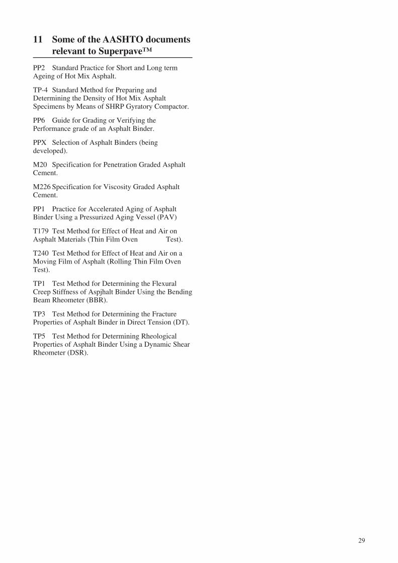
29
11 Some of the AASHTO documentsrelevant to Superpave™
PP2 Standard Practice for Short and Long termAgeing of Hot Mix Asphalt.
TP-4 Standard Method for Preparing andDetermining the Density of Hot Mix AsphaltSpecimens by Means of SHRP Gyratory Compactor.
PP6 Guide for Grading or Verifying thePerformance grade of an Asphalt Binder.
PPX Selection of Asphalt Binders (beingdeveloped).
M20 Specification for Penetration Graded AsphaltCement.
M226 Specification for Viscosity Graded AsphaltCement.
PP1 Practice for Accelerated Aging of AsphaltBinder Using a Pressurized Aging Vessel (PAV)
T179 Test Method for Effect of Heat and Air onAsphalt Materials (Thin Film Oven Test).
T240 Test Method for Effect of Heat and Air on aMoving Film of Asphalt (Rolling Thin Film OvenTest).
TP1 Test Method for Determining the FlexuralCreep Stiffness of Aspjhalt Binder Using the BendingBeam Rheometer (BBR).
TP3 Test Method for Determining the FractureProperties of Asphalt Binder in Direct Tension (DT).
TP5 Test Method for Determining RheologicalProperties of Asphalt Binder Using a Dynamic ShearRheometer (DSR).
30
12 Applicable British Standards forHMA
British Standards are being replaced by harmonisedEuropean standards under The European Committeefor Normalisation, or Comité Européen deNormalisation (CEN). However, overseas authoritiesmay have incorporated previous British Standardsinto their own design guides and much of theresearch work that forms the basis of this Road Notehas used British Standards as references. A list ofprovisional CEN standards is given in Chapter 13.
The British Standards Institution is the independentnational body for the preparation of BritishStandards. Enquiries should be addressed to the BSI,Linford Wood, Milton Keynes, MK14 6LE.
BS594 Hot rolled asphalt for roads and otherpaved areas.
Part 1 (1992) Constituent materials and asphaltmixtures.
Part 2 (1992) Transport, laying and compactionof rolled asphalt.
BS598 Sampling and examination of bituminousmixtures for roads and other paved areas.
Part 2 (1974) Methods for analytical testing.
Part 3 (1985) Methods for design and physicaltesting.
Part 100 (1987) Methods for sampling foranalysis.
Part 101 (1987) Methods for preparatory treatmentof samples for analysis.
Part 102 (1989) Analytical test methods.
Part 104 (1989) Sampling and examination ofbituminous mixtures for roads andother paved areas.
Part 110 (1998) Methods of test for thedetermination of wheel-trackingrate.
BS812 Sampling and testing of mineralaggregates, sands and fillers.
Part 1 (1975) Methods of determining particlesize and shape.
Part 2 (1975) Physical properties.
Part 100 (1990) General requirements forapparatus and calibration.
Part 101 (1984) Guide to sampling and testprocedures.
Part 102 (1989) Methods of sampling.
Part 103 (1989) Methods for determination ofparticle size distribution.
Section 103.2 (1989)Sedimentation test.
Part 105 Methods for determination ofparticle shape.
Section 105.1 (1989)Flakiness index.
Part 109 (1990) Methods of determination ofmoisture content.
Part 110 (1990) Method for determination ofaggregate crushing value (ACV).
Part 111 (1990) Methods for determination of tenper cent fines value (TFV).
Part 112 (1990) Methods for determination ofaggregate impact value (AIV).
Part 113 (1990) Method for determination ofaggregate abrasion value.
Part 114 (1989) Method for determination of thepolished-stone value.
Part 121 (1989) Method for determination ofsoundness.
BS1377 Methods of test for soils for civilengineering purposes.
Part 2 (1990) Classification tests.
BS 2000 Methods for test for petroleumand its products.
Part 397 (1995) Recovery of bitumen binders -Dichloromethane extraction rotaryfilm evaporator method.
Part 49 (1993) Determination of needlepenetration of bituminousmaterial.
Part 58 (1993) Determination of softening pointof bitumen - Ring and ballmethod.
BS 3690 Bitumens for building and civilengineering.
Part 1 (1989) Specifications for bitumens forroads and other paved areas. BS3690: Part 1: 1989.

31
BS 4987 Coated macadam for roads and otherpaved areas.
Part 1 (1993) Specifications for constituentmaterials and for mixtures.
Part 2 (1993) Transport, laying and compaction.
BS Drafts for developmentDD 213 (1993) Determination of the indirect
tensile stiffness modulus ofbituminous mixtures.
DD 226 (1996) Method for determining resistanceto permanent deformation ofbituminous mixtures subject tounconfined dynamic loading.
32
Applicable CEN Standards
Aggregates
prEN 13043 Aggregates for bituminous mixtures and surface dressings for roads and other trafficked areas
BS EN 932-1 Methods of sampling
BS EN 932-2 Methods for reducing laboratory samples
BS EN 932-5 Common equipment and calibration
BS EN 932-6 Definitions of repeatability and reproducibility
Aggregates - Tests for geometric properties of aggregates
BS EN 933-1 Determination of particle size distribution - Sieving method
BS EN 933-2 Determination of particle size - Test sieves, nominal size of apertures
BS EN 933-3 Determination of particle shape - Flakiness index
BS EN 933-4 Determination of particle shape - Shape index
BS EN 933-5 Percentage of crushed and broken surfaces in coarse aggregate
BS EN 933-6 Flow coefficient of coarse aggregate
BS EN 933-8 Sand equivalent test
Aggregates - Tests for mechanical and physical properties of aggregates
BS EN 1097-1 Determination of resistance to wear (Micro-Duval)
BS EN 1097-2 Methods for the determination of resistance to fragmentation
BS EN 1097-6 Determination of particle density and water absorption
BS EN 1097-7 Determination of the particle density of filler - Pyknometer method
BS EN 1097-8 Determination of the polished stone value
BS EN 1367-2 Magnesium sulfate test
Aggregates - Tests for fillers
BS EN 1744-4 Water susceptibility of fillers for bituminous mixtures
BS EN 13179-1 Delta ring and ball test
BS EN 13179-2 Bitumen number
Bitumen and bituminous binders
BS EN 12591 Specification for paving-grade bitumens
prEN 13924 Specification for hard paving-grade bitumens
prEN 14023 Specification for polymer modified bitumens
BS EN 58 Sampling of bituminous binders
13 Applicable CEN standards forHMA
European national standards will eventually bereplaced by harmonised standards produced by TheEuropean Committee for Normalisation, or ComitéEuropéen de Normalisation (CEN). The finalstandards will be published by each nationalstandardisation committee, such as the BritishStandards Institution, as their national Standards. It isexpected that the various specifications and testmethods for materials and design of asphalt will bepublished in December 2003. A list of some of thestandards is given below.
33
Applicable CEN Standards (continued)
BS EN 1426 Determination of needle penetration
BS EN 1427 Determination of softening point - Ring and Ball method
BS EN ISO 2592 Determination of flash and fire points
BS EN 12592 Determination of solubility
BS EN 12593 Determination of Fraass breaking point
BS EN 12594 Preparation of test samples
BS EN 12595 Determination of kinematic viscosity
BS EN 12596 Determination of dynamic viscosity by vacuum capillary
BS EN 12607-1 Determination of the resistance to hardening under the influence of heat and air - RTFOT method
BS EN 12607-2 Determination of the resistance to hardening under the influence of heat and air - TFOT method
BS EN 12607-3 Determination of the resistance to hardening under the influence of heat and air - RFT method
prEN 13302 Determination of viscosity of bitumen using a rotating spindle apparatus
Bituminous mixtures
prEN 13108-1 Material specification - Asphalt concrete
prEN 13108-2 Material specification - Asphalt concrete for very thin layers
prEN 13108-4 Material specification - Hot rolled asphalt
prEN13108-20 Quality - Type testing of asphalt mixes
BS EN 12697-1 Test methods - Soluble binder content
prEN 12697-2 Test methods - Particle size distribution
BS EN 12697-3 Test methods - Bitumen recovery, rotary evaporator
prEN 12697-5 Test methods - Maximum density
prEN 12697-6 Test methods - Bulk density, measurement
prEN 12697-8 Test methods - Air voids content
prEN 12697-9 Test methods - Reference density
prEN 12697-10 Test methods - Compatibility
prEN 12697-11 Test methods - Affinity between aggregate and binder
prEN 12697-12 Test methods - Moisture sensitivity
prEN 12697-15 Test methods - Segregation sensitivity
prEN 12697-19 Test methods - Permeability of porous asphalt specimen
prEN 12697-22 Test methods - Wheel tracking
prEN 12697-23 Test methods - Indirect tensile test
prEN 12697-26 Test methods - Stiffness
prEN 12697-27 Test methods - Sampling
prEN 12697-28 Test methods - Preparation of samples for determining binder content, water content and grading
prEN 12697-29 Test methods - Dimensions of a bituminous specimen
prEN 12697-30 Test methods - Specimen preparation by impact compactor
prEN 12697-31 Test methods - Specimen preparation by gyratory compactor
prEN 12697-32 Test methods - Specimen preparation by vibratory compactor
prEN 12697-33 Test methods - Specimen preparation by slab compactor
prEN 12697-34 Test methods - Marshall test
prEN 12697-35 Test methods - Laboratory mixing
prEN 12697-38 Test methods - Common equipment and calibration

34
Applicable CEN Standards (continued)
Surface characteristics - Road and Airfield
prEN 13036-1 Test methods - Measurement of pavement macro-texture depth using a patch technique
prEN 13036-2 Test methods - Procedure for determination of skid resistance of a pavement surface
prEN 13036-4 Test methods - Measurement of slip/skid resistance of a surface: The pendulum test
prEN 13036-5 Test methods - Determination of longitudinal evenness parameters or indicators
prEN 13036-6 Test methods - Profilometer-based method for measuring longitudinal evenness
prEN 13036-7 Test methods - Method of measuring surface irregularities: The straight edge test
prEN 13036-8 Test methods - Determining parameters or indicators for transverse evenness: Measurement method
Note: prEN denotes a standard at CEN committee approval stage
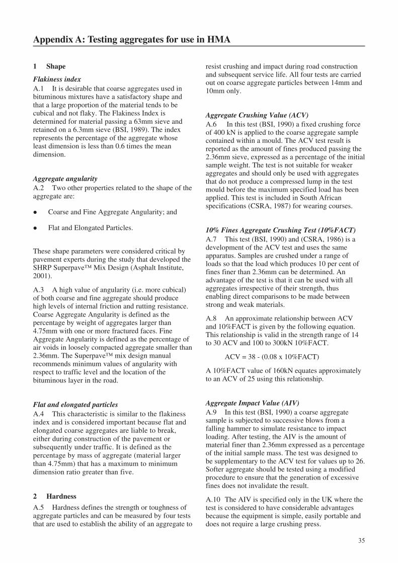
35
Appendix A: Testing aggregates for use in HMA
resist crushing and impact during road constructionand subsequent service life. All four tests are carriedout on coarse aggregate particles between 14mm and10mm only.
Aggregate Crushing Value (ACV)A.6 In this test (BSI, 1990) a fixed crushing forceof 400 kN is applied to the coarse aggregate samplecontained within a mould. The ACV test result isreported as the amount of fines produced passing the2.36mm sieve, expressed as a percentage of the initialsample weight. The test is not suitable for weakeraggregates and should only be used with aggregatesthat do not produce a compressed lump in the testmould before the maximum specified load has beenapplied. This test is included in South Africanspecifications (CSRA, 1987) for wearing courses.
10% Fines Aggregate Crushing Test (10%FACT)A.7 This test (BSI, 1990) and (CSRA, 1986) is adevelopment of the ACV test and uses the sameapparatus. Samples are crushed under a range ofloads so that the load which produces 10 per cent offines finer than 2.36mm can be determined. Anadvantage of the test is that it can be used with allaggregates irrespective of their strength, thusenabling direct comparisons to be made betweenstrong and weak materials.
A.8 An approximate relationship between ACVand 10%FACT is given by the following equation.This relationship is valid in the strength range of 14to 30 ACV and 100 to 300kN 10%FACT.
ACV = 38 - (0.08 x 10%FACT)
A 10%FACT value of 160kN equates approximatelyto an ACV of 25 using this relationship.
Aggregate Impact Value (AIV)A.9 In this test (BSI, 1990) a coarse aggregatesample is subjected to successive blows from afalling hammer to simulate resistance to impactloading. After testing, the AIV is the amount ofmaterial finer than 2.36mm expressed as a percentageof the initial sample mass. The test was designed tobe supplementary to the ACV test for values up to 26.Softer aggregate should be tested using a modifiedprocedure to ensure that the generation of excessivefines does not invalidate the result.
A.10 The AIV is specified only in the UK where thetest is considered to have considerable advantagesbecause the equipment is simple, easily portable anddoes not require a large crushing press.
1 Shape
Flakiness indexA.1 It is desirable that coarse aggregates used inbituminous mixtures have a satisfactory shape andthat a large proportion of the material tends to becubical and not flaky. The Flakiness Index isdetermined for material passing a 63mm sieve andretained on a 6.3mm sieve (BSI, 1989). The indexrepresents the percentage of the aggregate whoseleast dimension is less than 0.6 times the meandimension.
Aggregate angularityA.2 Two other properties related to the shape of theaggregate are:
! Coarse and Fine Aggregate Angularity; and
! Flat and Elongated Particles.
These shape parameters were considered critical bypavement experts during the study that developed theSHRP Superpave™ Mix Design (Asphalt Institute,2001).
A.3 A high value of angularity (i.e. more cubical)of both coarse and fine aggregate should producehigh levels of internal friction and rutting resistance.Coarse Aggregate Angularity is defined as thepercentage by weight of aggregates larger than4.75mm with one or more fractured faces. FineAggregate Angularity is defined as the percentage ofair voids in loosely compacted aggregate smaller than2.36mm. The Superpave™ mix design manualrecommends minimum values of angularity withrespect to traffic level and the location of thebituminous layer in the road.
Flat and elongated particlesA.4 This characteristic is similar to the flakinessindex and is considered important because flat andelongated coarse aggregates are liable to break,either during construction of the pavement orsubsequently under traffic. It is defined as thepercentage by mass of aggregate (material largerthan 4.75mm) that has a maximum to minimumdimension ratio greater than five.
2 Hardness
A.5 Hardness defines the strength or toughness ofaggregate particles and can be measured by four teststhat are used to establish the ability of an aggregate to
36
Los Angeles Abrasion (LAA)A.11 In this test (ASTM, C131, C535) an aggregatesample is subjected to attrition and impact by steelballs whilst rotating within a steel cylindrical drum ata prescribed rate for a set number of revolutions. Oncompletion of the test, the sample is screened on a1.70mm sieve. The coarser fraction is washed, ovendried and weighed. The loss in weight expressed as apercentage of the original sample weight is the LosAngeles Abrasion Value.
3 Durability
A.12 Durability is measured with reference to eithermechanical deterioration or a combination ofmechanical and physico-chemical deterioration. Inthe first case it is assessed by abrasion tests in thesecond by soundness tests.
Aggregate Abrasion Value (AAV)A.13 This provides an estimate of the surface wearof the aggregate and is particularly relevant for thespecification of materials designed to provide goodresistance to skidding such as coated chippings,coarse aggregate for porous asphalt and surfacedressing chippings. The test method (BSI, 1990)consists of holding a prepared aggregate sample,under a constant load, against a revolving lap withthe addition of abrasive sand for a set number ofrevolutions. The AAV is given by the loss in weightexpressed as a percentage of the initial sample.
Polished Stone Value (PSV)A.14 This is a predictive measure of thesusceptibility of aggregate used in wearing coursesand surface dressings to polishing under traffic andhence increase the risk of wet skidding at low speeds(BSI, 1989). The recommended value of PSVdepends on traffic levels and site characteristics.Accelerated polishing of aggregate samples isachieved by simulating the polishing effect of tyres.A rotating wheel passes over the aggregate sampleexerting a total force of 725N. A solution of cornemery and water is fed to the surface of the tyre. Thepolish of the sample with relation to a controlaggregate is measured using a standard pendulumfriction tester. Calibration of the friction tester ismaintained by the use of the control aggregate whichcan be obtained from TRL. Maintaining a supply ofcontrol and calibration aggregate in developingcountries may make the test difficult to sustain.
Water absorptionA.15 High water absorption in aggregates usuallyindicates low durability and can also cause problemsduring HMA design. It can be routinely determined
as part of the procedure to measure the relativedensities of the various size fractions of aggregate(BSI, 1975) since it is the difference in mass betweensaturated surface dry and oven dried aggregateexpressed as a percentage of the oven dried samplemass. In the UK, coarse aggregate having a waterabsorption of 2 per cent or less is considered durable.A value greater than this necessitates a soundness testto check compliance with specifications. No value ofwater absorption is given for fine aggregate. SouthAfrican specifications (CSRA, 1987) distinguishbetween coarse and fine aggregate, defined asparticles larger and smaller than 4.75mm, and call formaximum values of 1 and 1.5 per cent respectively.
Soundness - sodium or magnesium testA.16 These two tests, which are identical inprocedure, can be carried out on both coarse and fineaggregate and they estimate the degree of resistanceof the aggregate to in-service weathering. Anaggregate sample is exposed to, normally, five cyclesof immersion in a saturated solution of either sodiumor magnesium sulphate followed by oven drying. Theresult, calculated from the AASHTO test method (T-104), is the total percentage loss of material while theBritish Standard method (BSI, 1989) reports thepercentage material retained during the test. Therequired properties given in Table 4.1 are expressedas percentage material lost during the test.
A.17 Both these tests are considered severe and it isknown that they can give variable results dependingon aggregate characteristics such as shape, size,porosity and permeability. In reality, the test maymeasure the number of friable particles among soundaggregates rather than its general performance.Furthermore, the tests are relatively time consumingand expensive. They are normally only applicablewhere an absolute minimum of aggregatedeterioration is required such as on airfields,motorways and trunk roads. However, they may beuseful for testing aggregate obtained from newsources and rock which is thought to be susceptible torapid weathering such as partially degraded basalt.
4 Cleanliness
A.18 Ideally, aggregate should be free of all silt andclay size particles. During HMA production, the‘free’ silt and clay particles are removed by the dustextraction process or are included as filler. However,any fine material stuck to the aggregate may not beremoved and can prevent the bitumen fromcompletely coating the aggregate. Excess clay canalso cause ‘balling’ on contact with bitumen.
37
Decantation testA.19 This test is a development of the British StandardSieve Test (BSI, 1985). Initially the dry aggregatesample is agitated to simulate the treatment it receivesduring transit at the asphalt plant. A deflocculatingagent and ultrasonic vibration is then used to dislodgeadherent fine particles before wet sieving using a 63µmsieve to determine their proportion.
Sand equivalent valueA.20 This test (AASHTO T176, ASTM D: 2419) isutilised to establish the proportion of detrimentalclay-like or plastic fines in fine aggregate passing the4.75mm sieve. In the test, oven-dried fine aggregateand a solution of calcium chloride, glycerine andformaldehyde are mixed and poured into a graduatedcylinder. Agitation loosens the plastic fines from thecoarser sand-like particles and, after further additionof solution, the plastic fines are forced intosuspension. At the end of a prescribed sedimentationperiod the heights of sand and clay are measured. TheSand Equivalent Value is the ratio of the height of thesand to clay, expressed as a percentage.
Plasticity indexA.21 This is defined as a range of moisture content,expressed as a percentage of the mass of an ovendried aggregate sample passing a 425µm sieve,within which the material is in a plastic state (BSI,1990). It is the numerical difference between theliquid and plastic limit of the material. The liquid andplastic limits are difficult to determine for materialsof relatively low plasticity and, in such cases, a limitof 2 per cent in the linear shrinkage test will be easierto carry out and to use as a confirmatory test.
5 Bitumen affinity
A.22 Various techniques can be used to test theadhesion between bitumen and aggregate in thepresence of water and hence assess the ability ofaggregates to resist stripping.
Static Immersion testsA.23 These tests are not quoted in any aggregatespecifications used for HMA. They are generallyunreliable both in terms of repeatability andreproducibility and they are more relevant to surfacedressing design. If other suitable apparatus isunavailable the AASHTO T182 test may be useful.
A.24 In this Static Immersion test, coarse aggregateis coated with a known amount of bitumen and thenimmersed in distilled water for 48 hours. At the endof this period the degree of stripping is assessed byvisually estimating if the percentage of bitumen lefton the chippings is greater or less than 95 per cent.
This level was chosen because it is the point where areasonable degree of reproducibility is achieved.
Immersion strength testsA.25 In the Immersion Mechanical test (Whiteoak,1990) Marshall samples are immersed in water,maintained at 60°C, for 48 hours. The stability of thesoaked samples is expressed as a percentage of thestability of samples measured by the standardMarshall method, where samples are immersed inwater at 60°C for 30 minutes. The samples may firstbe vacuum treated under water to ensure completesaturation. A minimum value of 75 per cent retainedstability should be attained for satisfactory resistanceto damage by moisture. A compression test isspecified by AASHTO (T165) and ASTM (D1075).There is some doubt as to the usefulness of the tests,particularly with AC designed for heavy trafficconditions where initial voids in the mix (VIM) are at8 per cent. Tests under vacuum with VIM of 6 percent may give a better indication of moisturesensitivity.
A.26 A more severe test (AASHTO T283) isspecified for Superpave™ mix design (see paragraphD.24) and has been adopted in the Australianprovisional mix design procedure. It is considered togive a more reliable indication of moisture sensitivitythan the Immersion Mechanical test.
A.27 If an aggregate is known to be susceptible tostripping, or the tests outlined above indicate that thisis the case, then 1 to 2 per cent of fresh hydrated limeor Portland cement can be used as part of the filler toimprove adhesion.
6 Interpretation of test results
A.28 The recommendations in this Road Note arebased on several standards, including BritishStandard Institution, American AASHTO andASTM tests, Australian and South Africanspecifications. Tests, even with the same name, maynot give comparable results due to subtledifferences in the test procedures or materials usedin the tests. An example of this is the flakinessindex where an immediate complication arises fromthe definition of the coarse aggregate fraction. TheUK test is carried out on material passing the 63mmsieve and retained on a 6.30mm sieve. The SouthAfrican test calls for material passing 75mm andretained on a 4.75mm sieve.
A.29 It is important, therefore, that authoritiesensure that definitions of materials and testspecifications are established and are carried out infull accordance with the relevant standard.
38
Appendix B: Testing bitumens for use in HMA
experience has shown is equivalent to the degree ofhardening observed during the mixing and laying ofHMA (Dickinson, 1975).
Bitumen durability testB.5 Developed by the Australian Road ResearchBoard, this test is an extended version of the RTFOTand has been shown to simulate the in-service ageingof the bitumen in thin seals over a period of years. Inthe test, a small portion of bitumen, already hardenedin the RTFOT, is deposited from solvent on the innerwalls of the glass container used in the RTFOT to givean even film approximately 20 microns thick. Thesefilms are then exposed to the action of air in a RTFOTtype oven modified to maintain a temperature of 100oCover long periods. The viscosity of the binder is thentested periodically using a sliding plate viscometer toestablish how long it takes until the bitumen reaches a‘critical viscosity’ (5.7 log Pa.s at 45oC and a shearrate of 5.10 -3 s -1). The conditioning of the bitumen cantake up to 21 days and therefore the test is notspecified for the day to day control of binders.
2 Consistency tests
B.6 Bitumens are thermoplastic materials and arecharacterised by their consistency or ability to flow atdifferent temperatures. The viscosity of a bitumendetermines how the material will behave at a giventemperature and over a temperature range. The basicunit of viscosity is the Pascal second (Pa.s) where 1Pa.s = 10 Poise. The absolute (or dynamic) viscosityof bitumen, measured in Pascal seconds, is the shearstress applied to a sample in Pascals divided by theshear rate per second. Viscosity can also be measuredin units of m2/s, or more commonly mm2/s (1mm2/s =1 centistoke). These units relate to kinematicviscosity, usually measured by capillary tubeviscometers. Kinematic viscosity is related toabsolute viscosity by the expression:
Kinematic viscosity = Absolute viscosity/Mass density
Penetration testB.7 This is an empirical test in which a prescribedneedle, weighted to 100gms, is allowed to bear on thesurface of the bitumen for 5 seconds. The bitumen isheld at a temperature of 25oC in a water bath. Thedepth, in units of 0.1mm, that the needle penetrates isthe penetration measurement. As the test temperaturerises, the bitumen gets softer and the penetrationvalue is higher. There is a linear relationship betweenthe logarithm of the penetration and temperaturedefined as (Pfeiffer and Van Doormaal, 1936):
1 Ageing tests and procedures
B.1 The objective of the laboratory tests describedin this Appendix is to ensure that bitumen to be usedin HMA will give satisfactory performance inservice. Tests are divided into those which are usedto specify the required properties of bitumen when itis delivered whilst others specify the limits ofacceptable changes in bitumen properties during thevarious stages of the HMA production process.
Loss on heating testB.2 This test is part of the UK specifications and issuitable for ranking bitumens according to theirtendency to harden and often indicates that a materialhas been contaminated with light oils. The ageingconditions in the test are akin to those in bulk storagebut nothing like those during mixing. In the test,samples of binder are placed on a rotating shelf in aventilated oven and maintained at 163oC for a periodof five hours, whilst the shelf rotates approximately 5-6times per minute. The samples are approximately55mm in diameter and 35mm deep. The maindisadvantage of the test is that the surface area tovolume ratio of the samples is too low and an oxidisedskin tends to form quickly on the surface of thebitumen. This skin hampers further oxidation, unlikemixing conditions where homogeneous hardening ofthe bitumen in thin films occurs on the aggregate.
Thin Film Oven Test (TFOT)B.3 Practical conditions are simulated somewhatbetter by this test in that, despite being heated in asimilar manner, the bitumen samples are onlyapproximately 3mm thick. It is claimed that theamount of hardening that takes place in this testapproximates that obtained in practice during storageand mixing. However, in the test, diffusion into thebitumen film is still limited and it is not possible toobtain homogeneous hardening. The test, therefore, isstill far from being ideal.
Rolling Thin Film Oven Test (RTFOT)B.4 This test was developed by the CalifornianState Highway Department and simulates the mixingprocess more closely. In this test cylindrical glasscontainers holding 35gms of bitumen are fixed on avertically rotating shelf. During the test the bitumenflows continuously around the inner surface of thecontainer in a relatively thin film with pre-heated airbeing blown periodically into the container. Thenormal test procedure uses a temperature of 163oCfor a period of 75 minutes. In this manner ahomogeneously aged binder is obtained which
39
Log pen = AT+C
Where, A is the temperature susceptibility, andC is a constant
B.8 The value of A varies from 0.015 to 0.06,showing that there is a considerable differencebetween the temperature susceptibility of differentbitumens. Pfeiffer and Van Doormaal preferred anexpression for the temperature susceptibility whichwould ensure a value of approximately zero forpaving bitumens and, for this reason, defined thePenetration Index (PI) by the equation:
50 2010
A PIPI
= −+
or
PI AA
= −+
20 5001 50
The value of the PI ranges from about -3 for highlytemperature susceptible bitumens to about +7 for theleast susceptible ones. The value of A, and hence PI,can be derived from penetration measurements at twotemperatures, T
1 and T
2, using the equation:
Apen at T pen at T
T T=
−−
log log1 2
1 2
Softening point testB.9 A number of specifications for penetrationgrade bitumens also require the softening point of thebinder.
B.10 For this test, two samples of bitumen areconfined in brass rings, loaded with steel balls, andsuspended 25mm above a metal plate in a beaker ofwater or glycerol. The liquid is then heated at aprescribed rate. As the bitumen softens, the balls andthe bitumen gradually sink towards the plate. At themoment the bitumen touches the plate thetemperature of the water is determined, and this isdesignated as the ring and ball softening point. In theASTM version of the test, the liquid bath is notstirred, as it is in the IP or BS method, andconsequently the ASTM results are generally 1.5oChigher than those recorded with the other methods.
B.11 The consistency of bitumen at the softeningpoint temperature (T
R&B) has been measured in terms
of penetration (Pfeiffer and Van Doormaal, 1936)and the penetration has been found to be 800.Therefore, substituting in the equation above:
Apen TT TR B
=−
−log log
&
1
1
800
Where, TR&B
is the ASTM softening point
The value of pen = 800 at TR&B
is valid for many, butnot all bitumens. Bitumens with a high wax contentand high PI values, in particular, do not necessarilyhave a penetration of 800 at T
R&B. However, the
equation generally provides an alternative, thoughslightly less accurate way of deriving the PI of abitumen.
Fraass breaking point test (Fraass, 1937)B.12 This is one of the very few tests which can beused to describe the behaviour of bitumens at verylow temperature. It is essentially a research toolwhich determines the temperature at which thebitumen reaches a critical stiffness and cracks. In thetest, a steel plaque 41 x 20mm, coated with 0.5mmthick film of bitumen, is slowly flexed and released.The temperature of the plaque is decreased at 1oC perminute until the bitumen cracks. The temperature atwhich the sample cracks is called the breaking pointand represents an equi-stiffness temperature. It hasbeen shown that the bitumen has a stiffness of2.1x109 Pa at fracture.
Measurement of bitumen viscosityB.13 As the relationship between penetration andviscosity is often different for bitumens refined fromdifferent crude sources, a number of authorities haveadopted bitumen specifications based on viscosity aswell as penetration. Viscosity specifications arenormally based on a viscosity range measured at60oC and a minimum value at 135oC. A temperatureof 60oC was chosen as it approximates to themaximum temperature of in-service asphaltsurfacings and 135oC because it approximates to thetemperature at mixing and laydown.
B.14 Two types of viscosity test at 60oC are incommon use in the USA and both employ capillarytube viscometers. They are the Asphalt InstituteVacuum Viscometer and the Cannon-ManningVacuum Viscometer and both devices are calibratedusing a standard calibrating oil. They work in asimilar way by measuring the time taken for thebinder, at 60oC, to flow between two timing marksunder a prescribed vacuum. This time, whencorrected by the calibration factor, gives the value ofviscosity in poises.
B.15 Penetration grade bitumens are sufficientlyfluid at 135oC to flow through capillary tubes undergravitational forces alone. Therefore a vacuum is notrequired and a different type of viscometer is used.The one in most common use in the USA is theZeitfuchs Cross-Arm Viscometer, which is alsocalibrated with standard calibrating oils. Theviscometer is housed in an oil bath maintained at135oC and the time taken for the bitumen to flowbetween two points, under gravity, is recorded. The
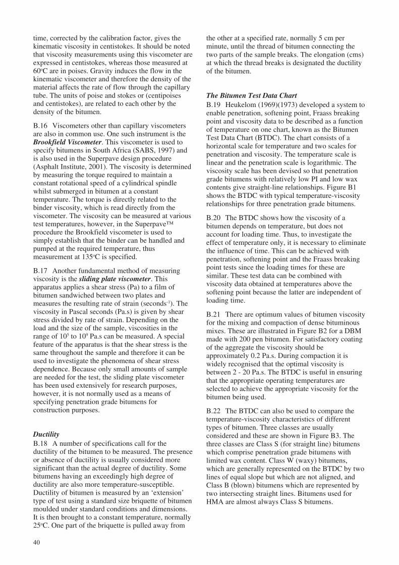
40
time, corrected by the calibration factor, gives thekinematic viscosity in centistokes. It should be notedthat viscosity measurements using this viscometer areexpressed in centistokes, whereas those measured at60oC are in poises. Gravity induces the flow in thekinematic viscometer and therefore the density of thematerial affects the rate of flow through the capillarytube. The units of poise and stokes or (centipoisesand centistokes), are related to each other by thedensity of the bitumen.
B.16 Viscometers other than capillary viscometersare also in common use. One such instrument is theBrookfield Viscometer. This viscometer is used tospecify bitumens in South Africa (SABS, 1997) andis also used in the Superpave design procedure(Asphalt Institute, 2001). The viscosity is determinedby measuring the torque required to maintain aconstant rotational speed of a cylindrical spindlewhilst submerged in bitumen at a constanttemperature. The torque is directly related to thebinder viscosity, which is read directly from theviscometer. The viscosity can be measured at varioustest temperatures, however, in the Superpave™procedure the Brookfield viscometer is used tosimply establish that the binder can be handled andpumped at the required temperature, thusmeasurement at 135oC is specified.
B.17 Another fundamental method of measuringviscosity is the sliding plate viscometer. Thisapparatus applies a shear stress (Pa) to a film ofbitumen sandwiched between two plates andmeasures the resulting rate of strain (seconds-1). Theviscosity in Pascal seconds (Pa.s) is given by shearstress divided by rate of strain. Depending on theload and the size of the sample, viscosities in therange of 105 to 109 Pa.s can be measured. A specialfeature of the apparatus is that the shear stress is thesame throughout the sample and therefore it can beused to investigate the phenomena of shear stressdependence. Because only small amounts of sampleare needed for the test, the sliding plate viscometerhas been used extensively for research purposes,however, it is not normally used as a means ofspecifying penetration grade bitumens forconstruction purposes.
DuctilityB.18 A number of specifications call for theductility of the bitumen to be measured. The presenceor absence of ductility is usually considered moresignificant than the actual degree of ductility. Somebitumens having an exceedingly high degree ofductility are also more temperature-susceptible.Ductility of bitumen is measured by an ‘extension’type of test using a standard size briquette of bitumenmoulded under standard conditions and dimensions.It is then brought to a constant temperature, normally25oC. One part of the briquette is pulled away from
the other at a specified rate, normally 5 cm perminute, until the thread of bitumen connecting thetwo parts of the sample breaks. The elongation (cms)at which the thread breaks is designated the ductilityof the bitumen.
The Bitumen Test Data ChartB.19 Heukelom (1969)(1973) developed a system toenable penetration, softening point, Fraass breakingpoint and viscosity data to be described as a functionof temperature on one chart, known as the BitumenTest Data Chart (BTDC). The chart consists of ahorizontal scale for temperature and two scales forpenetration and viscosity. The temperature scale islinear and the penetration scale is logarithmic. Theviscosity scale has been devised so that penetrationgrade bitumens with relatively low PI and low waxcontents give straight-line relationships. Figure B1shows the BTDC with typical temperature-viscosityrelationships for three penetration grade bitumens.
B.20 The BTDC shows how the viscosity of abitumen depends on temperature, but does notaccount for loading time. Thus, to investigate theeffect of temperature only, it is necessary to eliminatethe influence of time. This can be achieved withpenetration, softening point and the Fraass breakingpoint tests since the loading times for these aresimilar. These test data can be combined withviscosity data obtained at temperatures above thesoftening point because the latter are independent ofloading time.
B.21 There are optimum values of bitumen viscosityfor the mixing and compaction of dense bituminousmixes. These are illustrated in Figure B2 for a DBMmade with 200 pen bitumen. For satisfactory coatingof the aggregate the viscosity should beapproximately 0.2 Pa.s. During compaction it iswidely recognised that the optimal viscosity isbetween 2 - 20 Pa.s. The BTDC is useful in ensuringthat the appropriate operating temperatures areselected to achieve the appropriate viscosity for thebitumen being used.
B.22 The BTDC can also be used to compare thetemperature-viscosity characteristics of differenttypes of bitumen. Three classes are usuallyconsidered and these are shown in Figure B3. Thethree classes are Class S (for straight line) bitumenswhich comprise penetration grade bitumens withlimited wax content. Class W (waxy) bitumens,which are generally represented on the BTDC by twolines of equal slope but which are not aligned, andClass B (blown) bitumens which are represented bytwo intersecting straight lines. Bitumens used forHMA are almost always Class S bitumens.
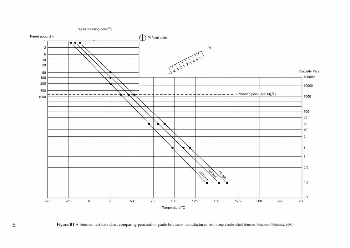
41
PI focal point
PI
-3-2
-10 1
23
45
67
Softening point (ASTM),oC
Fraass breaking point o
C
Penetration, dmm
1
2
5
10
20
50
100
200
500
1000
-50 -25 0 25 50 75 100 125 150 175 200 225 250
100000
10000
1000
100
50
20
10
5
2
1
0.5
0.2
0.1
Viscosity Pa.s
Temperature oC
200 pen100 pen
50 pen
Figure B1 A bitumen test data chart comparing penetration grade bitumens manufactured from one crude (Shell Bitumen Handbook Whiteoak, 1990)
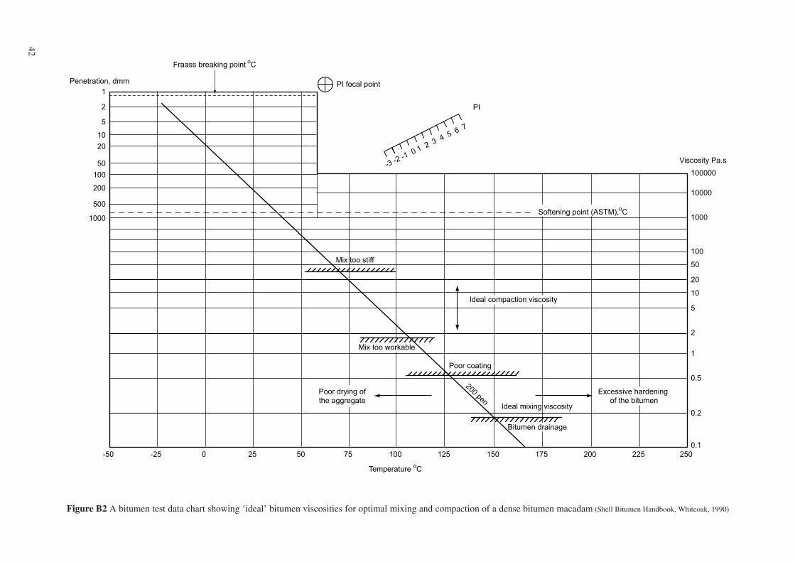
42
PI focal point
PI
-3-2
-10 1
23
45
67
Softening point (ASTM),oC
Fraass breaking point o
C
Penetration, dmm
1
2
5
10
20
50
100
200
500
1000
-50 -25 0 25 50 75 100 125 150 175 200 225 250
100000
10000
1000
100
50
20
10
5
2
1
0.5
0.2
0.1
Viscosity Pa.s
Temperature oC
Mix too stiff
Poor coating
Mix too workable
Bitumen drainage
200 penIdeal mixing viscosity
Excessive hardening
of the bitumen
Poor drying of
the aggregate
Ideal compaction viscosity
Figure B2 A bitumen test data chart showing ‘ideal’ bitumen viscosities for optimal mixing and compaction of a dense bitumen macadam (Shell Bitumen Handbook, Whiteoak, 1990)
43
Class S
Class W
Class B
PI focal point
PI
-3-2
-10 1
23
45
67
Softening point (ASTM),oC
Fraass breaking point o
C
Penetration, dmm
1
2
5
10
20
50
100
200
500
1000
-50 -25 0 25 50 75 100 125 150 175 200 225 250
100000
10000
1000
100
50
20
10
5
2
1
0.5
0.2
0.1
Viscosity Pa.s
Temperature oC
Figure B3 A bitumen test data chart comparing class S, B and W type bitumens (Shell Bitumen Handbook, Whiteoak, 1990)
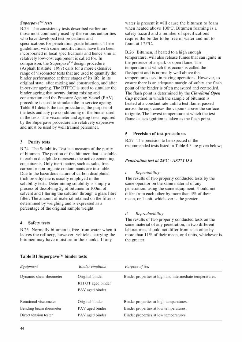
44
Table B1 Superpave™ binder tests
Equipment Binder condition Purpose of test
Dynamic shear rheometer Original binder Binder properties at high and intermediate temperatures.
RTFOT aged binder
PAV aged binder
Rotational viscometer Original binder Binder properties at high temperatures.
Bending beam rheometer PAV aged binder Binder properties at low temperatures.
Direct tension tester PAV aged binder Binder properties at low temperatures.
SuperpaveTM testsB.23 The consistency tests described earlier arethose most commonly used by the various authoritieswho have developed test procedures andspecifications for penetration grade bitumens. Theseguidelines, with some modifications, have then beenincorporated in local specifications and hence similarrelatively low-cost equipment is called for. Incomparison, the SuperpaveTM design procedure(Asphalt Institute, 1997) calls for a more extensiverange of viscometer tests that are used to quantify thebinder performance at three stages of its life: in itsoriginal state, after mixing and construction, and afterin-service ageing. The RTFOT is used to simulate thebinder ageing that occurs during mixing andconstruction and the Pressure Ageing Vessel (PAV)procedure is used to simulate the in-service ageing.Table B1 details the test procedures, the purpose ofthe tests and any pre-conditioning of the binder usedin the tests. The viscometer and ageing tests requiredby the Superpave procedure are relatively expensiveand must be used by well trained personnel.
3 Purity tests
B.24 The Solubility Test is a measure of the purityof bitumen. The portion of the bitumen that is solublein carbon disulphide represents the active cementingconstituents. Only inert matter, such as salts, freecarbon or non-organic contaminants are insoluble.Due to the hazardous nature of carbon disulphide,trichloroethylene is usually employed in thesolubility tests. Determining solubility is simply aprocess of dissolving 2g of bitumen in 100ml ofsolvent and filtering the solution through a glass fibrefilter. The amount of material retained on the filter isdetermined by weighing and is expressed as apercentage of the original sample weight.
4 Safety tests
B.25 Normally bitumen is free from water when itleaves the refinery, however, vehicles carrying thebitumen may have moisture in their tanks. If any
water is present it will cause the bitumen to foamwhen heated above 100oC. Bitumen foaming is asafety hazard and a number of specificationsrequire the binder to be free of water and not tofoam at 1750C.
B.26 Bitumen, if heated to a high enoughtemperature, will also release fumes that can ignite inthe presence of a spark or open flame. Thetemperature at which this occurs is called theflashpoint and is normally well above thetemperatures used in paving operations. However, toensure there is an adequate margin of safety, the flashpoint of the binder is often measured and controlled.The flash point is determined by the Cleveland OpenCup method in which the sample of bitumen isheated at a constant rate until a test flame, passedacross the cup, causes the vapours above the surfaceto ignite. The lowest temperature at which the testflame causes ignition is taken as the flash point.
5 Precision of test procedures
B.27 The precision to be expected of therecommended tests listed in Table 4.3 are given below;
Penetration test at 25oC - ASTM D 5
i RepeatabilityThe results of two properly conducted tests by thesame operator on the same material of anypenetration, using the same equipment, should notdiffer from each other by more than 4% of theirmean, or 1 unit, whichever is the greater.
ii ReproducibilityThe results of two properly conducted tests on thesame material of any penetration, in two differentlaboratories, should not differ from each other bymore than 11% of their mean, or 4 units, whichever isthe greater.
45
Softening Point - ASTM D 36
Using distilled water
i RepeatabilityThe results of two properly conducted tests by the sameoperator using the same apparatus on the same sampleof bitumen should not differ by more than 1.2oC.
ii ReproducibilityThe results of two properly conducted tests from twolaboratories on the same sample of bitumen shouldnot differ by more than 2.0oC.
Flash point by Cleveland open cup - ASTM D 92
i RepeatabilityThe difference between two properly conductedresults obtained by the same operator with the sameapparatus and the same sample of bitumen should notexceed 8oC.
ii ReproducibilityThe difference between two properly conducted testsobtained from different laboratories on the samesample of bitumen should not exceed 17oC.
Solubility - ASTM D 2042
i Repeatability (guide only)The difference between two properly conductedresults obtained by the same operator with the sameapparatus and the same sample of bitumen should notexceed 0.1%.
ii Reproducibility (guide only)The difference between two properly conducted testsobtained from different laboratories on the samesample of bitumen should not exceed 0.26%.
TFOT - ASTM D 1754
Loss by mass
i RepeatabilityThe results of two properly conducted tests by thesame operator on the same sample of bitumen, usingthe same equipment, should not differ from eachother by more than 8% of their mean.
ii ReproducibilityThe results of two properly conducted tests on thesame sample of bitumen, in two differentlaboratories, should not differ from each other bymore than 40% of their mean.
Percentage of retained penetration
i RepeatabilityThe results of two properly conducted tests by thesame operator on the same sample of bitumen, usingthe same equipment, should not differ from eachother by more than 4%.
ii ReproducibilityThe results of two properly conducted tests on thesame sample of bitumen, in two differentlaboratories, should not differ from each other bymore than 8%.
DuctilityValues for the repeatability and reproducibility of theductility test have not been fully developed.
46
Appendix C: Marshall design method and volumetric design
Design of aggregate gradingC.7 Using the results of the sieve analysis obtainedfor each source of aggregate, a blend is computedwhich conforms to the specified aggregate particlesize distribution. This can be most easily achievedusing a computer spreadsheet or by graphicalmethods such as those described in the AsphaltInstitute Manual MS-2. It may be found necessary tochange one or more of the aggregate sources to meetthe specified particle size distribution.
C.8 The selection of aggregate sources may also beconstrained by the number of cold feed bins that areavailable at the plant. It is preferable to obtain additionalcold feed bins rather than pre-mixing two sources ofaggregate before placing into a cold feed bin.
BitumenC.9 A bulk sample of bitumen should be takenfrom either the storage tank or the delivery tanker.Bitumen samples should not be kept at the mixingtemperature for longer than an hour during any testprocedure. It is advisable, therefore, that the bulksample of bitumen is divided into half-litre containersby pouring at as low a temperature as possible. In thisway smaller volumes of bitumen can be heated whenrequired. Containers of cold bitumen should not beheated over naked flames. Heating in an oven or on asand tray is recommended.
Determination of mixing and compactiontemperaturesC.10 The following properties of the bitumen aremeasured:
i Penetration at 25°C.
ii Softening point (temperature at whichpenetration is assumed to be 800).
iii Viscosity at approximately 105° to 115°C,135°C and 160°C.
iv Specific gravity.
The results of tests i) to iii) are plotted on a bitumentest data chart (Whiteoak,1990), illustrated inAppendix B. The plot will indicate the temperature-viscosity characteristics of the bitumen and enableselection of the ranges of ideal mixing and compactiontemperatures. The specific gravity of bitumen isrequired for the volumetric design of the mix.
1 Introduction
C.1 The standard Marshall method is suitable forthe design and field control of HMA mixturescontaining aggregates with a maximum size of up to25mm. Aggregates are prepared and blended to givesamples which conform to a selected particle sizedistribution. Initial mix design samples are preparedthat cover a range of bitumen contents and are thensubjected to a level of compaction which is related tothe expected traffic, in terms of equivalent standardaxles, to be carried in the design life of the HMAlayer(s). The properties of the compacted samples arethen determined. These properties include; bulkdensity, air voids, and stability and deformationcharacteristics under load. If the mix properties donot meet specified mix design criteria, the mix mustbe reformulated and the tests repeated until anacceptable design is established.
2 Materials
C.2 For the initial mix design it is advisable toobtain sufficient quantities of coarse aggregate, fineaggregate, filler and bitumen to allow tests to berepeated if necessary or to test different aggregategradings. For each Marshall design a total of 25kg ofaggregate and 5 litres of bitumen are needed to makethree briquettes for each bitumen content and toallow for some wastage. The materials must berepresentative of those to be used on the project.
C.3 For HMA taken from an asphalt plant it isimportant to complete the Marshall compactionbefore the samples have cooled below therecommended compaction temperature. Insulatedcontainers of large enough volume should be used fortransporting the material to satisfy this requirement.
C.4 It is important to note that the manufacture of testsamples with reheated or remoulded materials will notconform to the test procedures upon which this methodwas developed and may give misleading results.
AggregatesC.5 Bulk samples taken from each source ofnominal size aggregate are reduced in the laboratoryby riffling or quartering to give enough material tocomplete the mix design programme. If additionalfiller is to be added during production then sufficientmaterial should be obtained from the relevant sourcefor use in the mix design process.
C.6 Representative samples of each aggregatesource and filler are subjected to wet sieve analysisand specific gravity tests. It is important that thesieve sizes used for the sieve analysis of theaggregates are the same as those specified in the finalmix gradation.
47
3 Preparation of test samples
Mass of aggregate requiredC.11 The amount of aggregate required for eachsample is that which will be sufficient to makecompacted specimens 63.5 ± 1.27mm high. This isnormally approximately 1.2kg and should beconfirmed by compacting a trial sample of 1.2kg ofblended aggregate mixed at the estimated optimumbitumen content (see paragraph C.13 below). If theheight of the trial specimen falls outside the specifiedlimits then the weight of aggregate used should beadjusted according to the following equation:
Adjusted weight = (weight of aggregate used)specimen height (mm) obtained
63 5. *C1
C.12 Having determined the weight of aggregaterequired, a minimum of 21 samples of aggregatecomplying with the design particle size distributionare placed in metal containers. Fifteen samples areheated to a temperature not exceeding 28°C abovethe mixing temperature as determined in C10 above.
Design bitumen contentC.13 The design bitumen content for the selectedblend of aggregates is determined by testingspecimens prepared at bitumen contents which spanthe expected design value. The expected design valueis estimated from the following formula (AsphaltInstitute, 1994):
DBC = 0.035a + 0.04b + Kc + F C2
where, DBC = approximate design bitumencontent, per cent by total weightof mix
a = per cent of mineral aggregateretained on the 2.36mm sieve
b = per cent of mineral aggregatepassing the 2.36mm sieve andretained on the 0.075mm sieve
c = per cent of mineral aggregatepassing the 0.075mm sieve
K = 0.15 for 11-15% passing the0.075mm sieve;
0.18 for 6-10% passing the0.075mm sieve;
0.20 for 5% or less passing the0.075mm sieve;
F = 0-2%. Based on absorption ofbitumen. In the absence of otherdata, a value of 0.7 is suggested.
C.14 The aggregate samples are used to maketriplicate specimens at the estimated optimumbitumen content and at two increments of 0.5 per centabove and below this optimum. If the estimatedbitumen content proves to be different to the actualvalue then it may be necessary to use the spareaggregate samples to make specimens at one or twoadditional bitumen contents.
MixingC.15 Before mixing, the half-litre containers ofbitumen are heated in an oven to the ideal mixingtemperature as determined in C10 above. Mixingshould be done in a mechanical mixer with a bowlcapacity of approximately 4 litres. The mixing bowl,mechanical stirrers and any other implements to beused in the mixing procedure must be pre-heated tothe mixing temperature. The heated aggregate sampleis placed in the mixing bowl and thoroughly mixedusing a trowel or similar tool. A crater is formed inthe centre of the mixed aggregate into which therequired weight of bitumen is poured. Mixing withthe mechanical mixer will then produce a mixturewith a uniform distribution of bitumen.
CompactionC.16 The pre-heated mould, base plate, filling collarand an inserted paper disc should be pre-assembledso that the sample can be compacted immediatelyafter mixing is completed.
C.17 The mould is filled with the mixed materialand the contents spaded vigorously with a heatedspatula or trowel, 15 times around the perimeter and10 times over the interior. The surface of the materialis then smoothed to a slightly rounded shape ontowhich another paper disc is placed.
C.18 The temperature of the mix prior tocompaction must be within the determined limits (seeC10 above). The mould, base plate and filling collarare transferred to the Marshall compaction apparatusand the sample compacted by the specified number ofblows of the Marshall hammer. After compaction, themould assembly is removed and dismantled so thatthe mould can be inverted. The equipment isreassembled and the same number of blows areapplied to the inverted sample. The mould assemblyis then placed on a bench where the base plate, fillingcollar and paper discs are removed.
C.19 The mould and the specimen are allowed tocool in air to a temperature at which there will be nodeformation of the specimen during extraction fromthe mould using an extrusion jack. The compactedbriquette is labelled and allowed to cool to roomtemperature ready for testing the following day. Thewhole procedure is then repeated on the remainingprepared samples.
48
4 Testing of specimens
C.20 The briquettes are then tested to determinetheir volumetric composition and strengthcharacteristics.
Bulk specific gravity determinationC.21 The bulk specific gravity is determined foreach briquette at 25°C in accordance with the testprocedure described in ASTM D2726.
Stability and flow testingC.22 After measuring the bulk specific gravity thebriquettes are immersed in a water bath at 60°C ±1°C for 35 ± 5 minutes. Each briquette is thenremoved in turn and tested on a Marshall crushingapparatus to determine the stability and flow values.The mean value of stability and flow for eachtriplicate set of briquettes is calculated and recorded.
Determination of VIMC.23 The maximum specific gravity of the mixes ateach bitumen content must be determined to enableVIM to be calculated (see paragraph C.38). Aftercompletion of stability and flow tests, two of eachtriplicate set of briquettes are dried to constantweight in an oven at 105 ± 5°C. Each pair ofbriquettes is combined to give bulk samples to betested in accordance with the ASTM D2041procedure for the determination of maximumspecific gravity of the mixes.
Test dataC.24 The test results are plotted and smooth ‘bestfit’ curves drawn. The graphs plotted are:-
i VIM v bitumen content.
ii VFB v bitumen content.
iii VMA v bitumen content.
iv Stability v bitumen content.
v Flow v bitumen content.
vi BSG of mix v bitumen content.
Confirmation of design bitumen contentC.25 The design bitumen content is obtained fromthe relationship between VIM and bitumen contentdetermined in the Marshall test. The VIMrequirement is paramount after which it is necessaryto ensure that all of the remaining specified mixcriteria are also met (see Chapter 6).
C.26 If any of the criteria are not met or if it isconsidered that a more economical mix can bedesigned, then the whole design procedure will haveto be repeated using an alternative blend ofaggregates, particle size distribution or both.
5 Volumetric analysis
Determination of specific gravity for volumetricanalysis.C.27 Because it is the volume of the individualcomponents that is important for satisfactory mixdesign (see Chapter 5), the Bulk Specific Gravity(BSG) of each type of material must be measured sothat volumes can be computed from the weightswhen necessary. The nomenclature and test methodsused for volumetric analysis are shown in Table C1.
C.28 Coarse aggregates may have been obtainedfrom more than one quarry and the SG of individualsizes from a common aggregate source may bedifferent. Fine material may be crusher dust, sand ora blend of the two. The mineral filler fraction may becrushed rock or have added material such as hydratedlime or cement, the BSGs of which are very differentand must be tested separately.
C.29 Determination of the BSGs of the aggregates isbased on the oven dried weight. Accuracy ofmeasurements are important and it is recommendedthat they are determined to four significant figures, iethree decimal places. If the BSGs of the differentaggregate sizes do not differ by more than 0.2 thenthe inaccuracies produced by proportioning byweight rather than by volume will be small.
C.30 The BSGs of the individual coarse aggregatefractions, the fine aggregate and mineral fillerfractions are used to calculate the Bulk SpecificGravity (G
sb) of the total aggregate using the
following formula:
GP P P
PG
PG
PG
sbn
n
n
=+ +
+ +
1 2
1
1
2
2
....
.... C3
where, Gsb
= bulk specific gravity forthe total aggregate.
P1, P
2... P
n= individual percentages by
weight of aggregates.
G1, G
2... G
n= individual bulk specific
gravities of aggregates.
C.31 During production of HMA it is essential thatthe plant produces the same aggregate blend that isadopted for the laboratory design mix. To complete thevolumetric analysis of a bituminous mix (see Figure5.2) it is necessary to determine the maximum specificgravity (G
mm) of the loose HMA, the BSG of the
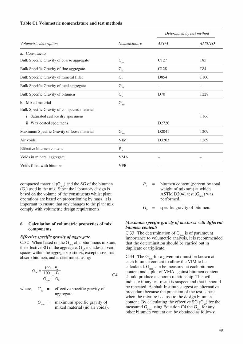
49
Table C1 Volumetric nomenclature and test methods
Determined by test method
Volumetric description Nomenclature ASTM AASHTO
a. Constituents
Bulk Specific Gravity of coarse aggregate Gca
C127 T85
Bulk Specific Gravity of fine aggregate Gfa
C128 T84
Bulk Specific Gravity of mineral filler Gf
D854 T100
Bulk Specific Gravity of total aggregate Gsb
– –
Bulk Specific Gravity of bitumen Gb
D70 T228
b. Mixed material Gmb
Bulk Specific Gravity of compacted material
i Saturated surface dry specimens T166
ii Wax coated specimens D2726
Maximum Specific Gravity of loose material Gmm
D2041 T209
Air voids VIM D3203 T269
Effective bitumen content Pbe
– –
Voids in mineral aggregate VMA – –
Voids filled with bitumen VFB – –
compacted material (Gmb
) and the SG of the bitumen(G
b) used in the mix. Since the laboratory design is
based on the volume of the constituents whilst plantoperations are based on proportioning by mass, it isimportant to ensure that any changes to the plant mixcomply with volumetric design requirements.
6 Calculation of volumetric properties of mixcomponents
Effective specific gravity of aggregateC.32 When based on the G
mm of a bituminous mixture,
the effective SG of the aggregate, Gse, includes all void
spaces within the aggregate particles, except those thatabsorb bitumen, and is determined using:
GP
GPG
seb
mm
b
b
=−
−
100100 C4
where, Gse
= effective specific gravity ofaggregate.
Gmm
= maximum specific gravity ofmixed material (no air voids).
Pb
= bitumen content (percent by totalweight of mixture) at whichASTM D2041 test (G
mm) was
performed.
Gb
= specific gravity of bitumen.
Maximum specific gravity of mixtures with differentbitumen contentsC.33 The determination of G
mm is of paramount
importance to volumetric analysis, it is recommendedthat the determination should be carried out induplicate or triplicate.
C.34 The Gmm
for a given mix must be known ateach bitumen content to allow the VIM to becalculated. G
mm can be measured at each bitumen
content and a plot of VMA against bitumen contentshould produce a smooth relationship. This willindicate if any test result is suspect and that it shouldbe repeated. Asphalt Institute suggest an alternativeprocedure because the precision of the test is bestwhen the mixture is close to the design bitumencontent. By calculating the effective SG (G
se) for the
measured Gmm,
using Equation C4 the Gmm
for anyother bitumen content can be obtained as follows:
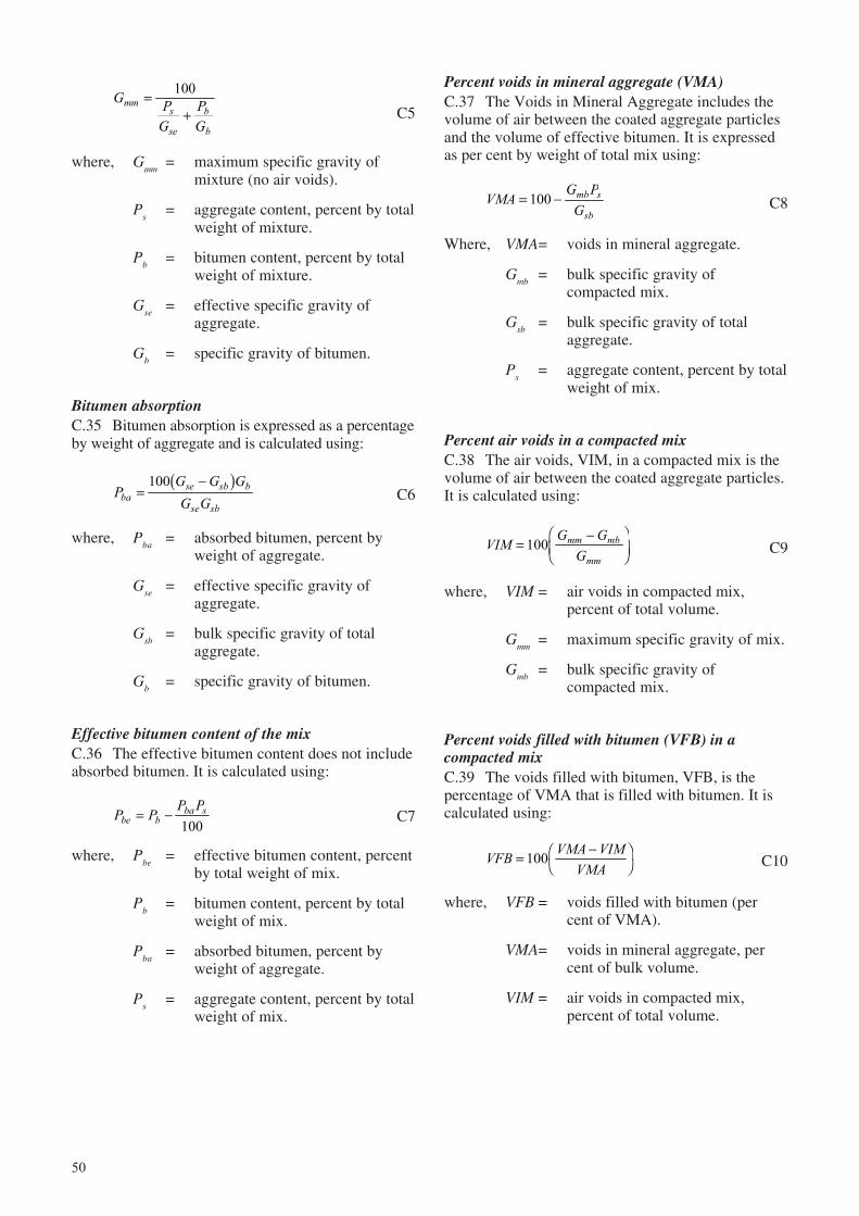
50
G PG
PG
mms
se
b
b
=+
100
C5
where, Gmm
= maximum specific gravity ofmixture (no air voids).
Ps
= aggregate content, percent by totalweight of mixture.
Pb
= bitumen content, percent by totalweight of mixture.
Gse
= effective specific gravity ofaggregate.
Gb
= specific gravity of bitumen.
Bitumen absorptionC.35 Bitumen absorption is expressed as a percentageby weight of aggregate and is calculated using:
PG G GG Gba
se sb b
se sb=
−100b gC6
where, Pba
= absorbed bitumen, percent byweight of aggregate.
Gse
= effective specific gravity ofaggregate.
Gsb
= bulk specific gravity of totalaggregate.
Gb
= specific gravity of bitumen.
Effective bitumen content of the mixC.36 The effective bitumen content does not includeabsorbed bitumen. It is calculated using:
P PP P
be bba s= −100
C7
where, Pbe
= effective bitumen content, percentby total weight of mix.
Pb
= bitumen content, percent by totalweight of mix.
Pba
= absorbed bitumen, percent byweight of aggregate.
Ps
= aggregate content, percent by totalweight of mix.
Percent voids in mineral aggregate (VMA)C.37 The Voids in Mineral Aggregate includes thevolume of air between the coated aggregate particlesand the volume of effective bitumen. It is expressedas per cent by weight of total mix using:
VMAG P
Gmb s
sb= −100 C8
Where, VMA= voids in mineral aggregate.
Gmb
= bulk specific gravity ofcompacted mix.
Gsb
= bulk specific gravity of totalaggregate.
Ps
= aggregate content, percent by totalweight of mix.
Percent air voids in a compacted mixC.38 The air voids, VIM, in a compacted mix is thevolume of air between the coated aggregate particles.It is calculated using:
VIMG G
Gmm mb
mm=
−FHG
IKJ100 C9
where, VIM = air voids in compacted mix,percent of total volume.
Gmm
= maximum specific gravity of mix.
Gmb
= bulk specific gravity ofcompacted mix.
Percent voids filled with bitumen (VFB) in acompacted mixC.39 The voids filled with bitumen, VFB, is thepercentage of VMA that is filled with bitumen. It iscalculated using:
VFB VMA VIMVMA
= −FH
IK100 C10
where, VFB = voids filled with bitumen (percent of VMA).
VMA= voids in mineral aggregate, percent of bulk volume.
VIM = air voids in compacted mix,percent of total volume.
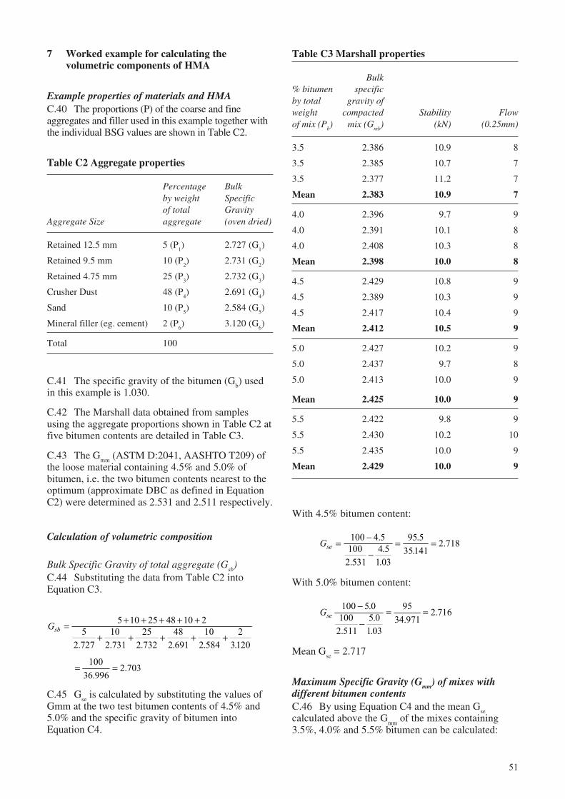
51
Table C2 Aggregate properties
Percentage Bulkby weight Specificof total Gravity
Aggregate Size aggregate (oven dried)
Retained 12.5 mm 5 (P1) 2.727 (G
1)
Retained 9.5 mm 10 (P2) 2.731 (G
2)
Retained 4.75 mm 25 (P3) 2.732 (G
3)
Crusher Dust 48 (P4) 2.691 (G
4)
Sand 10 (P5) 2.584 (G
5)
Mineral filler (eg. cement) 2 (P6) 3.120 (G
6)
Total 100
7 Worked example for calculating thevolumetric components of HMA
Example properties of materials and HMAC.40 The proportions (P) of the coarse and fineaggregates and filler used in this example together withthe individual BSG values are shown in Table C2.
With 4.5% bitumen content:
Gse = −
−= =100 4 5
1002 531
4 51 03
95 535141
2 718.
..
.
..
.
With 5.0% bitumen content:
Gse100 5 0
1002 511
5 01 03
9534 971
2 716−
−= =.
..
..
.
Mean Gse = 2.717
Maximum Specific Gravity (Gmm
) of mixes withdifferent bitumen contentsC.46 By using Equation C4 and the mean G
secalculated above the G
mm of the mixes containing
3.5%, 4.0% and 5.5% bitumen can be calculated:
C.41 The specific gravity of the bitumen (Gb) used
in this example is 1.030.
C.42 The Marshall data obtained from samplesusing the aggregate proportions shown in Table C2 atfive bitumen contents are detailed in Table C3.
C.43 The Gmm
(ASTM D:2041, AASHTO T209) ofthe loose material containing 4.5% and 5.0% ofbitumen, i.e. the two bitumen contents nearest to theoptimum (approximate DBC as defined in EquationC2) were determined as 2.531 and 2.511 respectively.
Calculation of volumetric composition
Bulk Specific Gravity of total aggregate (Gsb
)C.44 Substituting the data from Table C2 intoEquation C3.
Gsb = + + + + +
+ + + + +
5 10 25 48 10 25
2 72710
2 73125
2 73248
2 69110
2 5842
3120. . . . . .
= =10036 996
2 703.
.
C.45 Gse is calculated by substituting the values of
Gmm at the two test bitumen contents of 4.5% and5.0% and the specific gravity of bitumen intoEquation C4.
Table C3 Marshall properties
Bulk% bitumen specificby total gravity ofweight compacted Stability Flowof mix (P
b) mix (G
mb) (kN) (0.25mm)
3.5 2.386 10.9 8
3.5 2.385 10.7 7
3.5 2.377 11.2 7
Mean 2.383 10.9 7
4.0 2.396 9.7 9
4.0 2.391 10.1 8
4.0 2.408 10.3 8
Mean 2.398 10.0 8
4.5 2.429 10.8 9
4.5 2.389 10.3 9
4.5 2.417 10.4 9
Mean 2.412 10.5 9
5.0 2.427 10.2 9
5.0 2.437 9.7 8
5.0 2.413 10.0 9
Mean 2.425 10.0 9
5.5 2.422 9.8 9
5.5 2.430 10.2 10
5.5 2.435 10.0 9
Mean 2.429 10.0 9
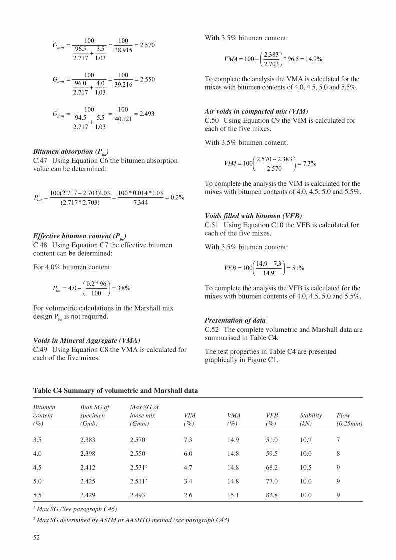
52
Table C4 Summary of volumetric and Marshall data
Bitumen Bulk SG of Max SG ofcontent specimen loose mix VIM VMA VFB Stability Flow(%) (Gmb) (Gmm) (%) (%) (%) (kN) (0.25mm)
3.5 2.383 2.5701 7.3 14.9 51.0 10.9 7
4.0 2.398 2.5501 6.0 14.8 59.5 10.0 8
4.5 2.412 2.5312 4.7 14.8 68.2 10.5 9
5.0 2.425 2.5112 3.4 14.8 77.0 10.0 9
5.5 2.429 2.4931 2.6 15.1 82.8 10.0 9
1 Max SG (See paragraph C46)2 Max SG determined by ASTM or AASHTO method (see paragraph C43)
Gmm =+
= =10096 5
2 7173 5
1 03
10038 915
2 570..
..
..
Gmm =+
= =10096 02 717
4 01 03
10039 216
2 550..
..
..
Gmm =+
= =10094 5
2 7175 5
1 03
10040 121
2..
..
..493
Bitumen absorption (Pba)C.47 Using Equation C6 the bitumen absorptionvalue can be determined:
Pba = − = =100 2 717 2 703 1 032 717 2 703
100 0 014 1 037 344
0 2%( . . ) .( . * . )
* . * ..
.
Effective bitumen content (Pbe
)C.48 Using Equation C7 the effective bitumencontent can be determined:
For 4.0% bitumen content:
Pbe = − FHIK =4 0 0 2 96
1003 8%. . * .
For volumetric calculations in the Marshall mixdesign P
be is not required.
Voids in Mineral Aggregate (VMA)C.49 Using Equation C8 the VMA is calculated foreach of the five mixes.
With 3.5% bitumen content:
VMA = − FHIK =100 2 383
2 70396 5 14 9%.
.* . .
To complete the analysis the VMA is calculated for themixes with bitumen contents of 4.0, 4.5, 5.0 and 5.5%.
Air voids in compacted mix (VIM)C.50 Using Equation C9 the VIM is calculated foreach of the five mixes.
With 3.5% bitumen content:
VIM = −FH
IK =100 2 570 2 383
2 5707 3%. .
..
To complete the analysis the VIM is calculated for themixes with bitumen contents of 4.0, 4.5, 5.0 and 5.5%.
Voids filled with bitumen (VFB)C.51 Using Equation C10 the VFB is calculated foreach of the five mixes.
With 3.5% bitumen content:
VFB = −FH
IK =100 14 9 7 3
14 951%. .
.
To complete the analysis the VFB is calculated for themixes with bitumen contents of 4.0, 4.5, 5.0 and 5.5%.
Presentation of dataC.52 The complete volumetric and Marshall data aresummarised in Table C4.
The test properties in Table C4 are presentedgraphically in Figure C1.
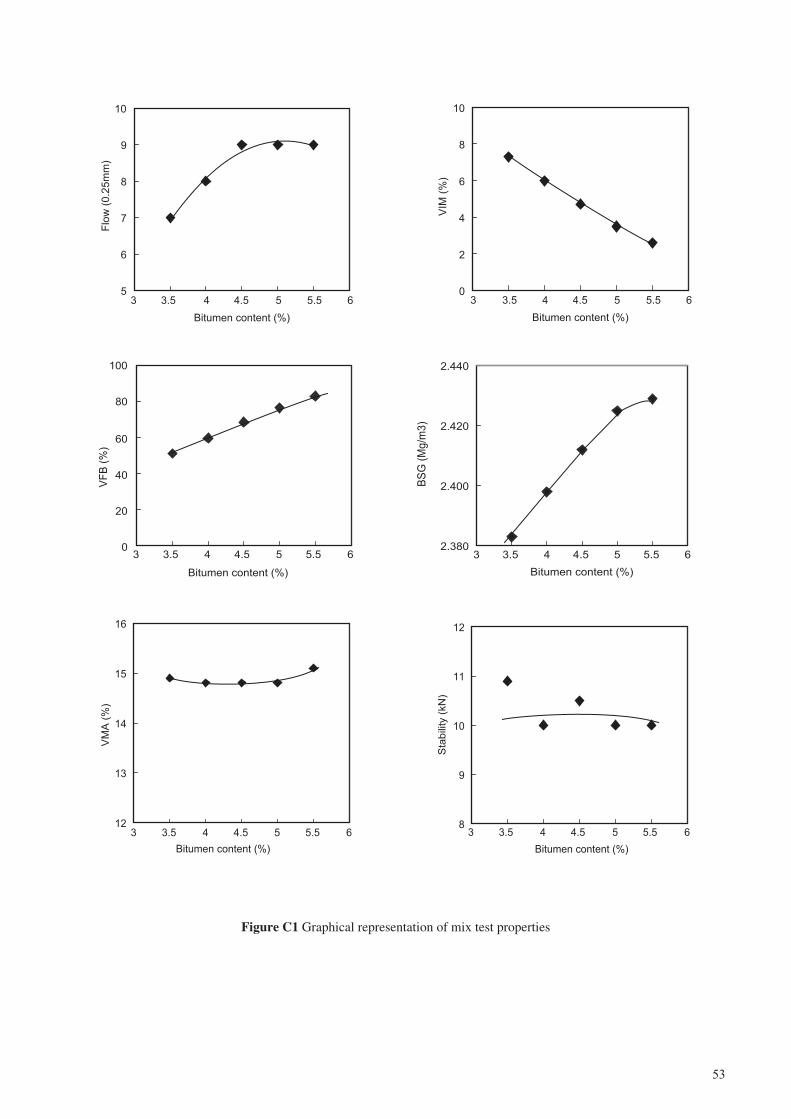
53
Figure C1 Graphical representation of mix test properties
5
6
7
8
9
10
3 3.5 4 4.5 5 5.5 6
Bitumen content (%)
Flo
w (
0.2
5m
m)
0
2
4
6
8
10
3 3.5 4 4.5 5 5.5 6
Bitumen content (%)
VIM
(%
)
0
20
40
60
80
100
3 3.5 4 4.5 5 5.5 6
Bitumen content (%)
VF
B (
%)
2.380
2.400
2.420
2.440
3 3.5 4 4.5 5 5.5 6
Bitumen content (%)
BS
G (
Mg
/m3)
8
9
10
11
12
3 3.5 4 4.5 5 5.5 6
Bitumen content (%)
Sta
bili
ty (
kN
)
12
13
14
15
16
3 3.5 4 4.5 5 5.5 6
Bitumen content (%)
VM
A (
%)
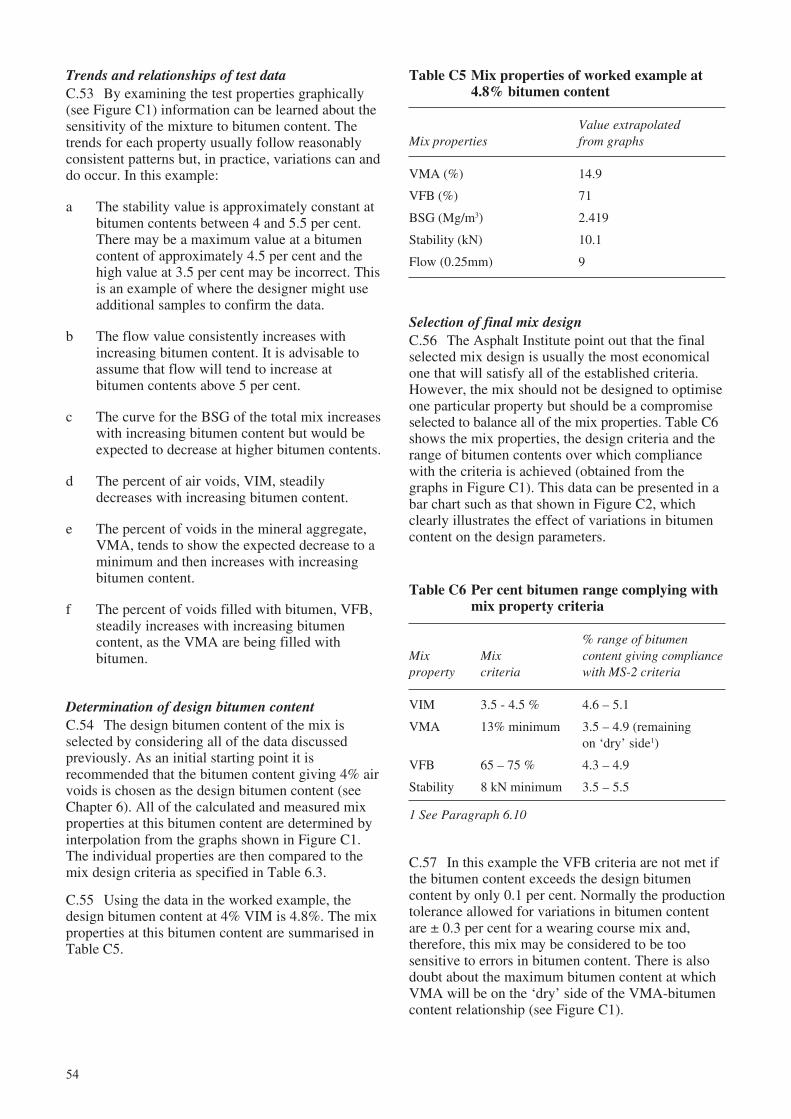
54
Table C5 Mix properties of worked example at4.8% bitumen content
Value extrapolatedMix properties from graphs
VMA (%) 14.9
VFB (%) 71
BSG (Mg/m3) 2.419
Stability (kN) 10.1
Flow (0.25mm) 9
Trends and relationships of test dataC.53 By examining the test properties graphically(see Figure C1) information can be learned about thesensitivity of the mixture to bitumen content. Thetrends for each property usually follow reasonablyconsistent patterns but, in practice, variations can anddo occur. In this example:
a The stability value is approximately constant atbitumen contents between 4 and 5.5 per cent.There may be a maximum value at a bitumencontent of approximately 4.5 per cent and thehigh value at 3.5 per cent may be incorrect. Thisis an example of where the designer might useadditional samples to confirm the data.
b The flow value consistently increases withincreasing bitumen content. It is advisable toassume that flow will tend to increase atbitumen contents above 5 per cent.
c The curve for the BSG of the total mix increaseswith increasing bitumen content but would beexpected to decrease at higher bitumen contents.
d The percent of air voids, VIM, steadilydecreases with increasing bitumen content.
e The percent of voids in the mineral aggregate,VMA, tends to show the expected decrease to aminimum and then increases with increasingbitumen content.
f The percent of voids filled with bitumen, VFB,steadily increases with increasing bitumencontent, as the VMA are being filled withbitumen.
Determination of design bitumen contentC.54 The design bitumen content of the mix isselected by considering all of the data discussedpreviously. As an initial starting point it isrecommended that the bitumen content giving 4% airvoids is chosen as the design bitumen content (seeChapter 6). All of the calculated and measured mixproperties at this bitumen content are determined byinterpolation from the graphs shown in Figure C1.The individual properties are then compared to themix design criteria as specified in Table 6.3.
C.55 Using the data in the worked example, thedesign bitumen content at 4% VIM is 4.8%. The mixproperties at this bitumen content are summarised inTable C5.
Selection of final mix designC.56 The Asphalt Institute point out that the finalselected mix design is usually the most economicalone that will satisfy all of the established criteria.However, the mix should not be designed to optimiseone particular property but should be a compromiseselected to balance all of the mix properties. Table C6shows the mix properties, the design criteria and therange of bitumen contents over which compliancewith the criteria is achieved (obtained from thegraphs in Figure C1). This data can be presented in abar chart such as that shown in Figure C2, whichclearly illustrates the effect of variations in bitumencontent on the design parameters.
Table C6 Per cent bitumen range complying withmix property criteria
% range of bitumenMix Mix content giving complianceproperty criteria with MS-2 criteria
VIM 3.5 - 4.5 % 4.6 – 5.1
VMA 13% minimum 3.5 – 4.9 (remainingon ‘dry’ side1)
VFB 65 – 75 % 4.3 – 4.9
Stability 8 kN minimum 3.5 – 5.5
1 See Paragraph 6.10
C.57 In this example the VFB criteria are not met ifthe bitumen content exceeds the design bitumencontent by only 0.1 per cent. Normally the productiontolerance allowed for variations in bitumen contentare ± 0.3 per cent for a wearing course mix and,therefore, this mix may be considered to be toosensitive to errors in bitumen content. There is alsodoubt about the maximum bitumen content at whichVMA will be on the ‘dry’ side of the VMA-bitumencontent relationship (see Figure C1).
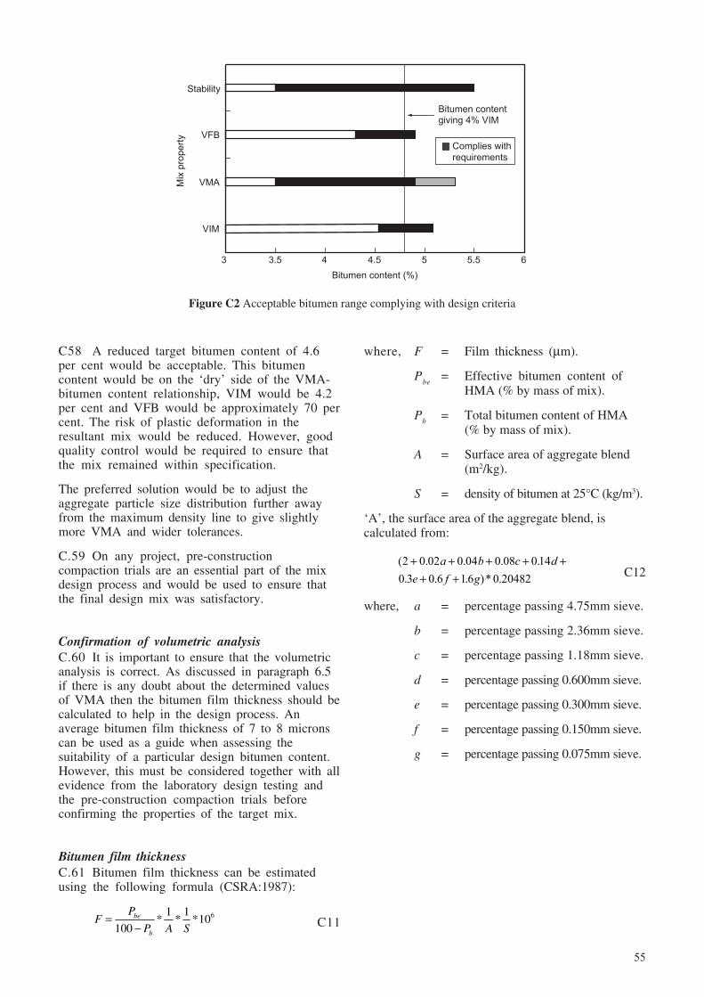
55
Figure C2 Acceptable bitumen range complying with design criteria
C58 A reduced target bitumen content of 4.6per cent would be acceptable. This bitumencontent would be on the ‘dry’ side of the VMA-bitumen content relationship, VIM would be 4.2per cent and VFB would be approximately 70 percent. The risk of plastic deformation in theresultant mix would be reduced. However, goodquality control would be required to ensure thatthe mix remained within specification.
The preferred solution would be to adjust theaggregate particle size distribution further awayfrom the maximum density line to give slightlymore VMA and wider tolerances.
C.59 On any project, pre-constructioncompaction trials are an essential part of the mixdesign process and would be used to ensure thatthe final design mix was satisfactory.
Confirmation of volumetric analysisC.60 It is important to ensure that the volumetricanalysis is correct. As discussed in paragraph 6.5if there is any doubt about the determined valuesof VMA then the bitumen film thickness should becalculated to help in the design process. Anaverage bitumen film thickness of 7 to 8 micronscan be used as a guide when assessing thesuitability of a particular design bitumen content.However, this must be considered together with allevidence from the laboratory design testing andthe pre-construction compaction trials beforeconfirming the properties of the target mix.
Bitumen film thicknessC.61 Bitumen film thickness can be estimatedusing the following formula (CSRA:1987):
61 1* * *10
100be
b
PF
P A S=
− C11
where, F = Film thickness (µm).
Pbe
= Effective bitumen content ofHMA (% by mass of mix).
Pb
= Total bitumen content of HMA(% by mass of mix).
A = Surface area of aggregate blend(m2/kg).
S = density of bitumen at 25°C (kg/m3).
‘A’, the surface area of the aggregate blend, iscalculated from:
( . . . .. . . )* .2 0 02 0 04 0 08 0140 3 0 6 16 0 20482
+ + + + ++ +
a b c de f g C12
where, a = percentage passing 4.75mm sieve.
b = percentage passing 2.36mm sieve.
c = percentage passing 1.18mm sieve.
d = percentage passing 0.600mm sieve.
e = percentage passing 0.300mm sieve.
f = percentage passing 0.150mm sieve.
g = percentage passing 0.075mm sieve.
Mix
pro
pe
rty
3 3.5 4 4.5 5 5.5 6
VIM
VMA
VFB
Stability
Bitumen content (%)
Complies with
requirements
Bitumen contentgiving 4% VIM
56
Appendix D: Superpave™
Performance tests for bitumenD.8 For any given road temperature and trafficloading the selected bitumen must also satisfyspecified requirements. These are:
i A minimum flash point temperature.
ii A maximum viscosity of 3Pas at 135°C.
iii Minimum dynamic shear at a temperatureappropriate to the road site.
iv After Rolling Thin Film Oven test:
a maximum percent loss in mass; and
b minimum dynamic shear at a temperatureappropriate to the road site.
v After ageing in a Pressure Ageing Vessel (PAV):
c maximum dynamic shear at a temperatureappropriate to the road site;
d physical hardening, tests on beams ofbitumen;
e creep stiffness criteria; and
f direct tension failure criteria.
D.9 Clearly, although the range between high andlow design temperatures in tropical countries willoften be less than in much of North America, theprinciples of Superpave can be adopted in developingcountries. The equipment required to carry out thebitumen performance tests listed above is relativelycomplex and expensive and well trained technicianswill be needed to operate it. A period of ‘calibration’will also be needed. During this time it will benecessary to establish procedures for estimating theappropriate maximum and minimum road surfacingtemperatures. Also, it cannot be assumed that therewill be a range of bitumens available from which asuitable material can be selected.
Aggregate propertiesD.10 Consensus properties were agreed by aselected panel of experts who relied upon theirextensive empirical knowledge of factors which arerelevant to conditions in the USA. The propertiesspecified, which are also relevant to developingcountries with tropical climates are:
1 Background
D.1 The Strategic Highway Research Programme(SHRP) was a five year, US$150 million project. Athird of these funds were directed at studies ofbitumen, aggregates, mix design procedures and theequipment necessary for a new mix designmethodology called Superpave.
D.2 The Asphalt Institute produced the followingmanuals for Superpave mix design:
i Performance graded asphalt binderspecifications and testing. Superpave SeriesNo.1 (SP-1), 1996.
ii Superpave™ Mix Design. Superpave Series No.2 (SP-2). Third Edition, 2001.
D.3 Authorities wishing to have detailed knowledgeabout Superpave mix design must also refer to newAASHTO Standards to ensure that the full requirementsof the test methods are obtained. Current standards arelisted in Chapter 11. An outline of the procedure isgiven below to indicate the general methodology.
2 Materials for Superpave™
D.4 All materials are subject to quality andperformance based assessments. When applied tobitumens these assessments are related to the resultsof physical tests. For aggregates therecommendations are largely for ‘consensusproperties’ and source properties, which are outlinedin paragraphs D10 and D11.
D.5 Mix acceptance is based on volumetriccomposition and compaction characteristics whichare specified for different levels of twenty-yeardesign traffic loading, expressed in terms ofequivalent standard axles (esa).
Selection of grade of bitumenD.6 The recommended procedure for the selectionof the correct grade of bitumen is to determine bothhigh and low pavement design temperatures. The hightemperature relates to the pavement temperature at adepth of 20mm below the road surface whilst the lowtemperature is determined for the surface of the road.
D.7 Methods of determining the road temperaturesfor design, and levels of reliability, are given in theManual. The Performance Grade bitumen (or PGbinder) is then selected to suit the temperatureconditions and this may be further adjusted if trafficloading conditions justify it.
57
i Coarse aggregate angularity.
ii Fine aggregate angularity.
iii Flat/elongated particles.
iv Clay content.
v Combined Bulk Specific Gravity.
vi Combined Apparent Specific Gravity.
Angularity is specified to ensure that good internalfriction is obtained in the aggregate structure so as toresist deformation of the asphalt under traffic.Limiting elongation reduces the chances of particlebreakage under load and limiting the clay contentenhances the bonding between bitumen andaggregate particles.
D.11 Source properties relate to the followingproperties:
i toughness;
ii soundness; and
iii deleterious material.
Toughness is measured by the Los Angeles abrasiontest. Soundness is measured by the sodium ormagnesium sulphate soundness test. Deleteriousmaterials are measured by the clay lumps and friableparticles test. Aggregate particle size distributionsmust satisfy the requirements summarised in TablesD1 and D2.
3 Compaction for Superpave™ mix design
D.12 A gyratory compactor is used which provides amethod of compaction that is more representative ofcompaction under road rollers than is the Marshallhammer. The specification of the gyratory compactoris important and the basic requirements for theSuperpave compactor are:
i A constant pressure of 600kPa on thecompacting ram.
ii A constant rate of rotation of the mould at 30gyrations per minute.
iii The mould is positioned at a compaction angleof 1.25 degrees.
D.13 In principle, asphalt mixes should be designedto be more resistant to compactive forces as eitherroad temperature or design traffic loading increases.
Table D1 Particle size distributions for Superpave™ HMA (AC type) wearing courses
Per cent passing sieve size
Nominal maximum size (mm)
19 12.5 9.5
Control Restricted Control Restricted Control RestrictedSieve points zone points zone points zonesize(mm) Min Max Min Max Min Max Min Max Min Max Min Max
25 100 –
19 90 100 100 –
12.5 – 90 90 100 100 –
9.5 – – – 90 90 100
4.75 – – – – – 90
2.36 23 49 34.6 34.6 28 58 39.1 39.1 32 67 47.2 47.2
1.18 – – 22.3 28.3 – – 25.6 31.6 – – 31.6 37.6
0.600 – – 16.7 20.7 – – 19.1 23.1 – – 23.5 27.5
0.300 – – 13.7 13.7 – – 15.5 15.5 – – 18.7 18.7
0.075 2 8 2 10 2 10
58
Table D3 Superpave™ gyratory compaction effort
Compaction parametersDesign traffic(esa x 106)1 N
initialN
designN
maximum
< 0.3 6 50 75
0.3 to < 32 7 75 115
3 to < 30 8 100 160
> 30 9 125 205
1 Design traffic is the anticipated project traffic levelexpected on the design lane over a 20-year period.Regardless of the actual design life of the roadway,determine the design esa for 20 years and choose theappropriate N
design level.
2 The agency may, at its discretion, specify this level ofcompaction for an estimated design traffic level ofbetween 3 and <10 million esa.
(See Asphalt Institute, Superpave Manual Series No. 2(SP-2) for other conditions.
The number of gyrations, defined as ‘Initial’ (Ninitial
),‘Design’ (N
design) and ‘Maximum’ (N
maximum), needed
to achieve these three specified levels of compactionshould agree with the values shown in Table D3.Other design requirements are also given in Table D4(AASHTO, MP2-01).
Preparation of mix design samplesD.14 Suitable aggregates and the appropriate gradeof bitumen are selected for the traffic loading andtemperature regimes at the road location.
D.15 There is no limit to the number of trialaggregate blends that can be tested. In SP-2 it isrecommended that three blends are tried and that allof the gradings pass below the restricted zone. Theblends are described as coarse, intermediate and fine.The grading of the coarse blend is near the minimumallowable per cent passing the nominal maximumsize, the 2.36mm sieve and the 0.075mm sieve. Theintermediate grading is not close to any of the controlpoint limits. The fine grading is close to themaximum per cent nominal maximum size and is justbelow the restricted zone.
Table D2 Particle size distributions for Superpave™ HMA (AC type) roadbase and binder courses
Roadbase Binder course
Per cent passing sieve size
Nominal size (mm)
37.5 25
Control Restricted Control RestrictedSieve points zone points zonesize(mm) Min Max Min Max Min Max Min Max
50 100 –
37.5 90 100 100 –
25 – 90 90 100
19 – – – 90
4.75 – – 34.7 34.7 – – 39.5 39.5
2.36 15 41 23.3 27.3 19 45 26.8 30.8
1.18 – – 15.5 21.5 – – 18.1 24.1
0.600 – – 11.7 15.7 – – 13.6 17.6
0.300 – – 10 10 – – 11.4 11.4
0.075 0 6 1 7
59
D16 It is suggested that, in order to obtain a goodunderstanding of the behaviour of local materials,investigators could also try an aggregate grading thatpasses through the restricted zone as well as above it.
D17 A method of calculating a trial bitumencontent is provided in the AI-SP2 manual. At leasttwo samples of each trial mix are mixed at theappropriate temperature and aged, to represent theeffect of plant mixing, by placing them in a forceddraft oven for 2 hours ± 5 minutes at a temperatureequal to the mixture’s compaction temperature ±3ºC. The mixtures should be stirred after 60 ± 5minutes to obtain uniform conditioning. Twoadditional, but uncompacted, samples are made forthe determination of maximum theoretical specificgravity.
D.18 The compaction temperature range of an HMAmixture is defined as the range of temperatures wherethe unaged bitumen has a kinematic viscosity ofapproximately 0.28 ± 0.03Pa.s measured inaccordance with ASTM D4402.
D.19 The samples are compacted to the appropriatenumber of gyrations selected from Table D3. Duringcompaction the height of the sample is monitoredand, knowing the mass of the mix and the volume ofthe mould, the bulk specific gravity of the mix can becalculated for any number of gyrations.
D.20 After compaction each sample is allowed topartially cool before being extracted from the mould.After fully cooling it’s bulk specific gravity(AASHTO T 166/ASTM D 2726) and maximumspecific gravity (G
mm) AASHTO T 209/ASTM D
2041) are determined.
D.21 Guidance is given on the calculation ofvolumetric properties for the compacted specimenswhich will then allow selection of the most suitableaggregate grading.
D.22 A complete mix design, covering a range ofbitumen contents, can then be carried out on samplesmade to the selected grading.
D.23 It is then a simple matter to calculate thevolumetric properties of the samples at any numberof gyrations and to determine a bitumen contentwhich gives 4 per cent VIM at N
design. The criteria
which must be met at this bitumen content aresummarised in Table D4.
Moisture sensitivityD.24 The sensitivity to moisture of the design mix isassessed by carrying out the AASHTO T 283 testprocedure. Six specimens are compacted to give 7per cent air voids and three of the specimens aresubjected to partial vacuum saturation. For regions
Table D4 Superpave™ HMA design requirements
Required relative density Voids (Percent of theoretical Minimum Voids in Mineral Filled
maximum specific gravity) Aggregate (VMA), (percent) withBitumen Filler to
Design Nominal maximum aggregate size, (mm) (VFB) 2 bindertraffic range ratio(esa x 106)1 N
initialN
designN
maximum37.5 25.0 19.0 12.5 9.5 (Percent) range
< 0.3 ≥ 91.5 70 – 803
0.3 – < 3 ≥ 90.5 65 – 78
3 – < 10 96.0 ≥ 98.0 11.0 12.0 13.0 14.0 15.0
0.6 – 1.25
10 – < 30 ≥ 89.0 65 - 754
≥ 30
1 Design traffic is the anticipated project traffic level expected on the design lane over a 20-year period. Regardless of theactual design life of the roadway, the design traffic is determined for 20 years.
2 For 37.5mm nominal maximum aggregate size mixtures, the specified lower limit of the VFB shall be 64 percent for alldesign traffic levels.
3 For 25.0mm nominal maximum aggregate size mixtures, the specified lower limit of the VFB shall be 67 percent fordesign traffic levels < 0.3 million esa.
4 For 9.5mm nominal maximum aggregate size mixtures, the specified VFB range shall be 73 to 76 percent for designtraffic levels > 3 million esa.
5 If the aggregate gradation passes beneath the boundaries of the restricted zone specified in Tables D1 or D2, the filler tobitumen ratio range may be increased from 0.6 – 1.2 to 0.8 –1.6 at the agency’s discretion.
t tt t
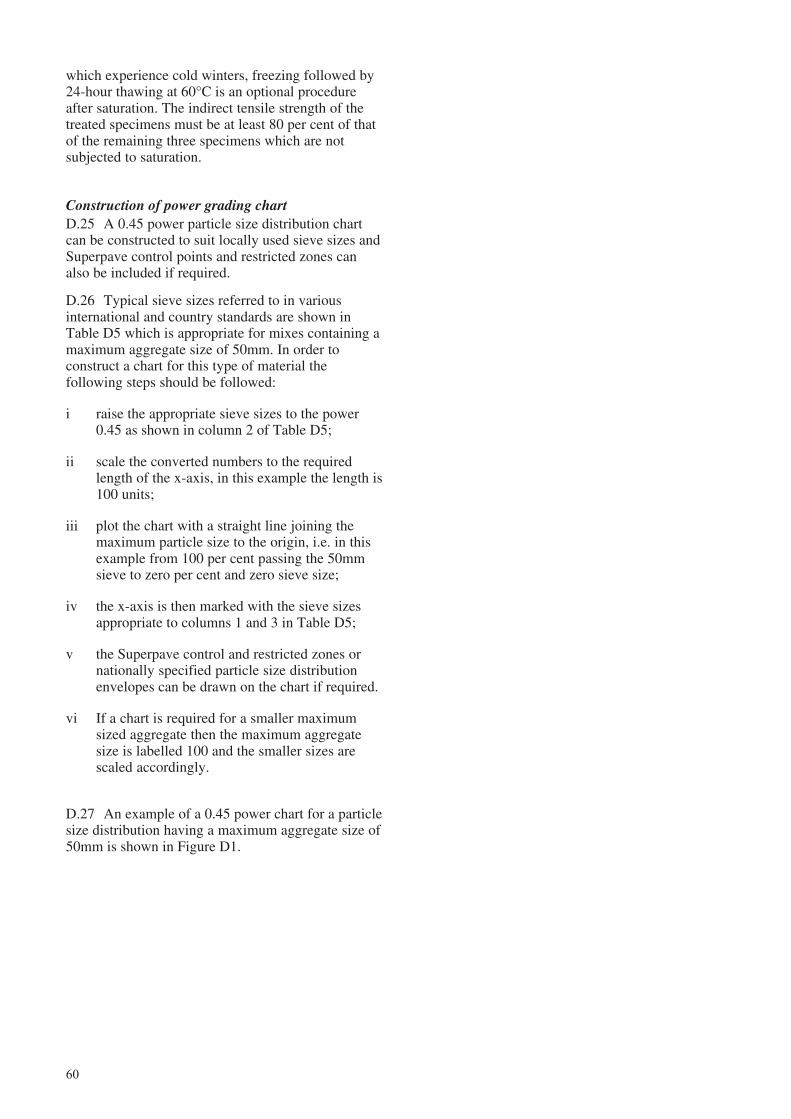
60
which experience cold winters, freezing followed by24-hour thawing at 60°C is an optional procedureafter saturation. The indirect tensile strength of thetreated specimens must be at least 80 per cent of thatof the remaining three specimens which are notsubjected to saturation.
Construction of power grading chartD.25 A 0.45 power particle size distribution chartcan be constructed to suit locally used sieve sizes andSuperpave control points and restricted zones canalso be included if required.
D.26 Typical sieve sizes referred to in variousinternational and country standards are shown inTable D5 which is appropriate for mixes containing amaximum aggregate size of 50mm. In order toconstruct a chart for this type of material thefollowing steps should be followed:
i raise the appropriate sieve sizes to the power0.45 as shown in column 2 of Table D5;
ii scale the converted numbers to the requiredlength of the x-axis, in this example the length is100 units;
iii plot the chart with a straight line joining themaximum particle size to the origin, i.e. in thisexample from 100 per cent passing the 50mmsieve to zero per cent and zero sieve size;
iv the x-axis is then marked with the sieve sizesappropriate to columns 1 and 3 in Table D5;
v the Superpave control and restricted zones ornationally specified particle size distributionenvelopes can be drawn on the chart if required.
vi If a chart is required for a smaller maximumsized aggregate then the maximum aggregatesize is labelled 100 and the smaller sizes arescaled accordingly.
D.27 An example of a 0.45 power chart for a particlesize distribution having a maximum aggregate size of50mm is shown in Figure D1.
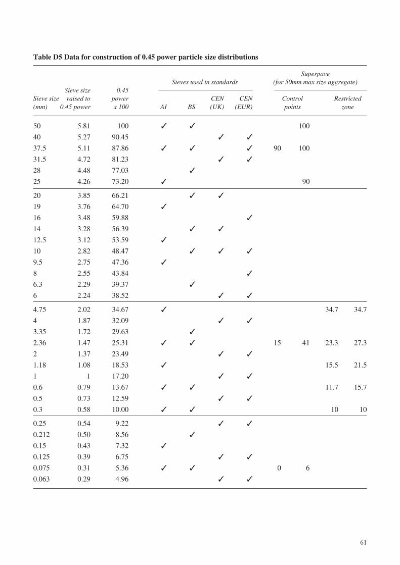
61
Table D5 Data for construction of 0.45 power particle size distributions
SuperpaveSieves used in standards (for 50mm max size aggregate)
Sieve size 0.45Sieve size raised to power CEN CEN Control Restricted(mm) 0.45 power x 100 AI BS (UK) (EUR) points zone
50 5.81 100 ✓ ✓ 100
40 5.27 90.45 ✓ ✓
37.5 5.11 87.86 ✓ ✓ ✓ 90 100
31.5 4.72 81.23 ✓ ✓
28 4.48 77.03 ✓
25 4.26 73.20 ✓ 90
20 3.85 66.21 ✓ ✓
19 3.76 64.70 ✓
16 3.48 59.88 ✓
14 3.28 56.39 ✓ ✓
12.5 3.12 53.59 ✓
10 2.82 48.47 ✓ ✓ ✓
9.5 2.75 47.36 ✓
8 2.55 43.84 ✓
6.3 2.29 39.37 ✓
6 2.24 38.52 ✓ ✓
4.75 2.02 34.67 ✓ 34.7 34.7
4 1.87 32.09 ✓ ✓
3.35 1.72 29.63 ✓
2.36 1.47 25.31 ✓ ✓ 15 41 23.3 27.3
2 1.37 23.49 ✓ ✓
1.18 1.08 18.53 ✓ 15.5 21.5
1 1 17.20 ✓ ✓
0.6 0.79 13.67 ✓ ✓ 11.7 15.7
0.5 0.73 12.59 ✓ ✓
0.3 0.58 10.00 ✓ ✓ 10 10
0.25 0.54 9.22 ✓ ✓
0.212 0.50 8.56 ✓
0.15 0.43 7.32 ✓
0.125 0.39 6.75 ✓ ✓
0.075 0.31 5.36 ✓ ✓ 0 6
0.063 0.29 4.96 ✓ ✓
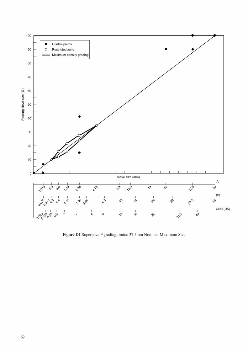
62
Figure D1 Superpave™ grading limits: 37.5mm Nominal Maximum Size
0
10
20
30
40
50
60
70
80
90
100
Sieve size (mm)
Pa
ssin
g s
ieve
siz
e (
%)
Control points
Restricted zone
Maximum density grading
AI
0.07
50.
30.
61.
182.
364.
75 9.5
12.5 19 25
37.5 50
BS
CEN (UK)0.
075
0.21
20.
30.
61.
182.
363.
35 6.3 10 14 20 28
37.5
0.06
3
0.12
50.
25 0.5 1 2 4 6 10 14 20
31.5 40
50
63
Appendix E: Performance tests for HMA design
subjected to traffic loading or to environmentalageing. However, such testing does haveconsiderable potential for ‘ranking’ mixes andidentifying those that would be unsuitable for use.
E.5 Performance tests are being developed byauthorities in several countries. It is important toremember that, in many cases different testconditions and requirements are specified even fortest methods having a common name and it is,therefore, presently difficult to give generalisedspecifications for these tests. The followingparagraphs describe some of the test methods and thealternative specifications that are used.
Mix stiffness modulus (or resilient modulus)E.6 Indirect Tensile Tests (ITT) using either thelatest version of the British Nottingham AsphaltTester (BSI, 1993), the Australian Materials TestingApparatus (MATTA), (Standards Australia, 1994), orother equipment complying with ASTMrecommendations offer reliable and appropriate testmethods to determine mix stiffness modulus.
Indirect tensile stiffnessE.7 In this test a defined pulse loading is appliedvertically across the diameter of the test specimenand the resultant peak transient horizontal diametricaldeformation measured. The resilient modulus isnormally found to be indirectly proportional to the airvoid content for a given mix. For laboratory-manufactured specimens, samples with 4 per centVIM are most relevant to design procedures.
E.8 Different test conditions and performancespecifications are recommended by authorities inseveral countries. The main differences aresummarised in Tables E1 to E3.
Specifications for Mix Stiffness (ITT)E.9 The UK specifications shown in Table E2below are at present in Draft form and have not beenfinalised. The specification applies to a macadammaterial used for the roadbase and binder courselayers with a void content of between 7-9%.
E.10 The Australian provisional mix design methodis based on the maximum particle size of theaggregate and the grade of bitumen. The grade ofbitumen is classified on the basis of the viscosity inPascal seconds (Pa.s) measured at 60°C.Specifications are under development but typicalcriteria for mixes containing 4-5% air voids are givenin Table E3.
1 Performance tests
E.1 Ensuring that the composition of a mix iscorrect and that the VIM value will not fall below 3%after trafficking is a vital part of the design process.However, the degree of aggregate interlock andfriction between particles also has an importantbearing on the resistance of a bituminous mix toshear failure. Although the Marshall design methodaddresses these problems it has been found that thereis poor correlation between measurements of stabilityand flow and subsequent performance in the road(Whiteoak, 1990). A better indication of the tendencyfor a mix to deform plastically under traffic is givenby the ‘Stiffness Quotient’ i.e. maximum stabilitydivided by the flow value. However, measurementsof both of these values usually have large variationsand, therefore, Stiffness Quotient values can also beunreliable.
E.2 Additional performance tests are thereforedesirable, particularly for the design of HMA whichmust carry more than 1 million esa during its designlife. Such tests can include:
i determination of mix stiffness moduli;
ii creep;
iii wheel tracking; and
iv shear tests.
E.3 Performance tests do not necessarily guaranteethe long term performance of an HMA. The FederalHighway Authority (FHWA), (www.tfhrc.gov. -January 2002) discusses the merits of six design testprocedures with particular reference to resistance torutting. These are:
i Marshall test.
ii Hveem stabilometer.
iii Gyratory Testing Machine.
iv Wheel-track testers.
v Superpave Shear Tester.
vi Creep Tests.
The FHWA points out that none of these tests arecapable of predicting rutting of HMA under traffic.
E.4 Design testing is also necessarily carried outon laboratory prepared samples which have not been
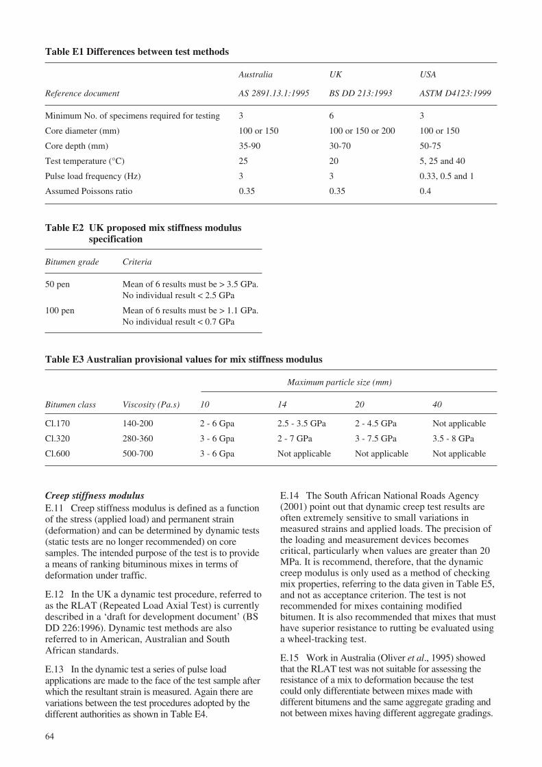
64
Table E1 Differences between test methods
Australia UK USA
Reference document AS 2891.13.1:1995 BS DD 213:1993 ASTM D4123:1999
Minimum No. of specimens required for testing 3 6 3
Core diameter (mm) 100 or 150 100 or 150 or 200 100 or 150
Core depth (mm) 35-90 30-70 50-75
Test temperature (°C) 25 20 5, 25 and 40
Pulse load frequency (Hz) 3 3 0.33, 0.5 and 1
Assumed Poissons ratio 0.35 0.35 0.4
Table E2 UK proposed mix stiffness modulusspecification
Bitumen grade Criteria
50 pen Mean of 6 results must be > 3.5 GPa.No individual result < 2.5 GPa
100 pen Mean of 6 results must be > 1.1 GPa.No individual result < 0.7 GPa
Table E3 Australian provisional values for mix stiffness modulus
Maximum particle size (mm)
Bitumen class Viscosity (Pa.s) 10 14 20 40
Cl.170 140-200 2 - 6 Gpa 2.5 - 3.5 GPa 2 - 4.5 GPa Not applicable
Cl.320 280-360 3 - 6 Gpa 2 - 7 GPa 3 - 7.5 GPa 3.5 - 8 GPa
Cl.600 500-700 3 - 6 Gpa Not applicable Not applicable Not applicable
Creep stiffness modulusE.11 Creep stiffness modulus is defined as a functionof the stress (applied load) and permanent strain(deformation) and can be determined by dynamic tests(static tests are no longer recommended) on coresamples. The intended purpose of the test is to providea means of ranking bituminous mixes in terms ofdeformation under traffic.
E.12 In the UK a dynamic test procedure, referred toas the RLAT (Repeated Load Axial Test) is currentlydescribed in a ‘draft for development document’ (BSDD 226:1996). Dynamic test methods are alsoreferred to in American, Australian and SouthAfrican standards.
E.13 In the dynamic test a series of pulse loadapplications are made to the face of the test sample afterwhich the resultant strain is measured. Again there arevariations between the test procedures adopted by thedifferent authorities as shown in Table E4.
E.14 The South African National Roads Agency(2001) point out that dynamic creep test results areoften extremely sensitive to small variations inmeasured strains and applied loads. The precision ofthe loading and measurement devices becomescritical, particularly when values are greater than 20MPa. It is recommend, therefore, that the dynamiccreep modulus is only used as a method of checkingmix properties, referring to the data given in Table E5,and not as acceptance criterion. The test is notrecommended for mixes containing modifiedbitumen. It is also recommended that mixes that musthave superior resistance to rutting be evaluated usinga wheel-tracking test.
E.15 Work in Australia (Oliver et al., 1995) showedthat the RLAT test was not suitable for assessing theresistance of a mix to deformation because the testcould only differentiate between mixes made withdifferent bitumens and the same aggregate grading andnot between mixes having different aggregate gradings.
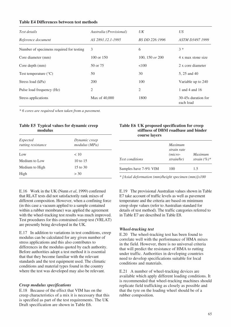
65
Table E6 UK proposed specification for creepstiffness of DBM roadbase and bindercourse layers
Maximumstrain rate(micro- Maximum
Test conditions strain/hr) strain (%)*
Samples have 7-9% VIM 100 1.5
* [Axial deformation (mm)/height specimen (mm)]x100
Table E4 Differences between test methods
Test details Australia (Provisional) UK US
Reference document AS 2891.12.1-1995 BS DD 226:1996 ASTM D3497 1999
Number of specimens required for testing 3 6 3 *
Core diameter (mm) 100 or 150 100, 150 or 200 4 x max stone size
Core depth (mm) 50 or 75 <100 2 x core diameter
Test temperature (°C) 50 30 5, 25 and 40
Stress load (kPa) 200 100 Variable up to 240
Pulse load frequency (Hz) 2 2 1 and 4 and 16
Stress applications Max of 40,000 1800 30-45s duration foreach load
* 6 cores are required when taken from a pavement.
Table E5 Typical values for dynamic creepmodulus
Expected Dynamic creeprutting resistance modulus (MPa)
Low < 10
Medium to Low 10 to 15
Medium to High 15 to 30
High > 30
E.16 Work in the UK (Nunn et al, 1999) confirmedthat RLAT tests did not satisfactorily rank mixes ofdifferent composition. However, when a confining force(in this case a vacuum applied to a sample containedwithin a rubber membrane) was applied the agreementwith the wheel-tracking test results was much improved.Test procedures for this constrained creep test (VRLAT)are presently being developed in the UK.
E.17 In addition to variations in test conditions, creepmodulus can be calculated for any given number ofstress applications and this also contributes todifferences in the modulus quoted by each authority.Before authorities adopt a test method it is essentialthat that they become familiar with the relevantstandards and the test equipment used. The climaticconditions and material types found in the countrywhere the test was developed may also be relevant.
Creep modulus specificationsE.18 Because of the effect that VIM has on thecreep characteristics of a mix it is necessary that thisis specified as part of the test requirements. The UKDraft specification are shown in Table E6.
E.19 The provisional Australian values shown in TableE7 take account of traffic levels as well as pavementtemperature and the criteria are based on minimumcreep slope values (refer to Australian standard fordetails of test method). The traffic categories referred toin Table E7 are described in Table E8.
Wheel-tracking testE.20 The wheel-tracking test has been found tocorrelate well with the performance of HMA mixesin the field. However, there is no universal criteriathat will predict the resistance of HMA to ruttingunder traffic. Authorities in developing countriesneed to develop specifications suitable for localconditions and materials.
E.21 A number of wheel-tracking devices areavailable which apply different loading conditions. Itis recommended that wheel-tracking machines shouldreplicate field trafficking as closely as possible andthat the tyre on the loading wheel should be of arubber composition.
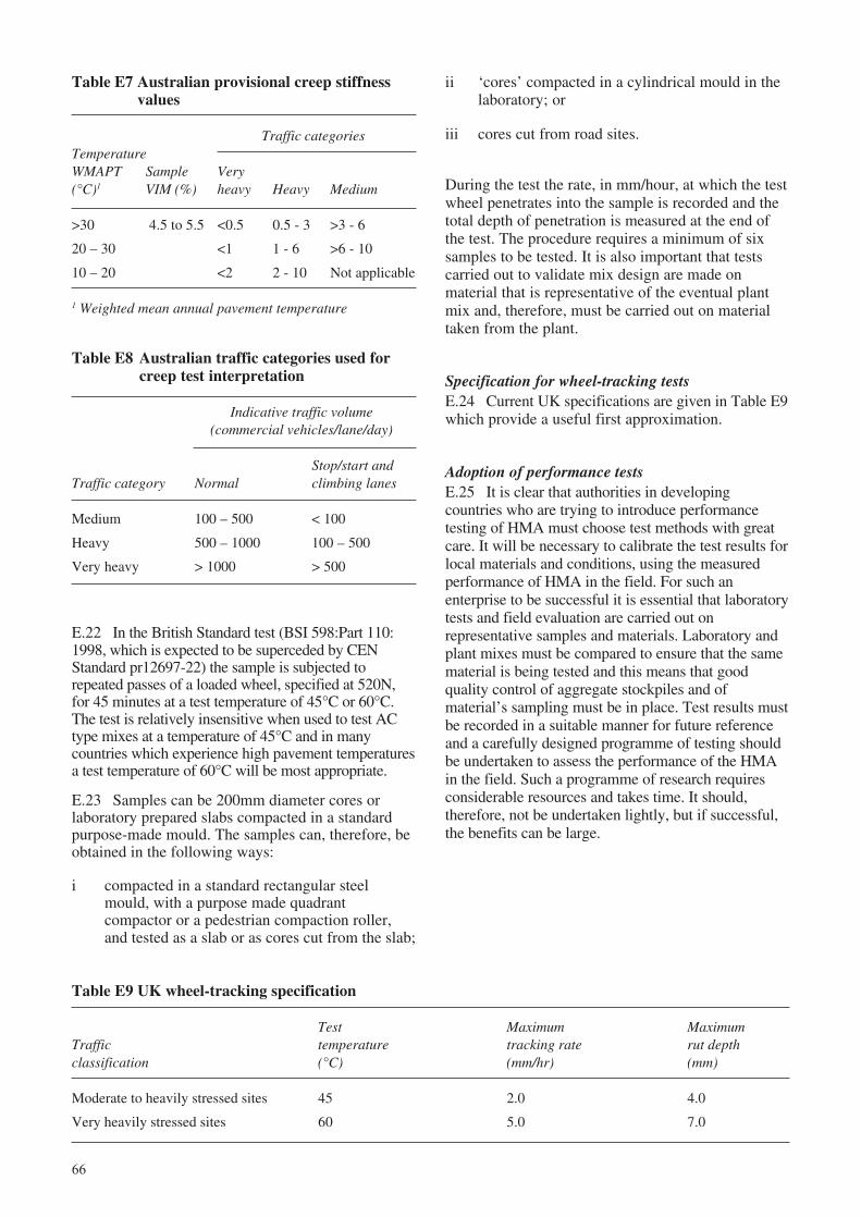
66
Table E7 Australian provisional creep stiffnessvalues
Traffic categoriesTemperatureWMAPT Sample Very(°C)1 VIM (%) heavy Heavy Medium
>30 4.5 to 5.5 <0.5 0.5 - 3 >3 - 6
20 – 30 <1 1 - 6 >6 - 10
10 – 20 <2 2 - 10 Not applicable
1 Weighted mean annual pavement temperature
Table E8 Australian traffic categories used forcreep test interpretation
Indicative traffic volume(commercial vehicles/lane/day)
Stop/start andTraffic category Normal climbing lanes
Medium 100 – 500 < 100
Heavy 500 – 1000 100 – 500
Very heavy > 1000 > 500
Table E9 UK wheel-tracking specification
Test Maximum MaximumTraffic temperature tracking rate rut depthclassification (°C) (mm/hr) (mm)
Moderate to heavily stressed sites 45 2.0 4.0
Very heavily stressed sites 60 5.0 7.0
ii ‘cores’ compacted in a cylindrical mould in thelaboratory; or
iii cores cut from road sites.
During the test the rate, in mm/hour, at which the testwheel penetrates into the sample is recorded and thetotal depth of penetration is measured at the end ofthe test. The procedure requires a minimum of sixsamples to be tested. It is also important that testscarried out to validate mix design are made onmaterial that is representative of the eventual plantmix and, therefore, must be carried out on materialtaken from the plant.
Specification for wheel-tracking testsE.24 Current UK specifications are given in Table E9which provide a useful first approximation.
Adoption of performance testsE.25 It is clear that authorities in developingcountries who are trying to introduce performancetesting of HMA must choose test methods with greatcare. It will be necessary to calibrate the test results forlocal materials and conditions, using the measuredperformance of HMA in the field. For such anenterprise to be successful it is essential that laboratorytests and field evaluation are carried out onrepresentative samples and materials. Laboratory andplant mixes must be compared to ensure that the samematerial is being tested and this means that goodquality control of aggregate stockpiles and ofmaterial’s sampling must be in place. Test results mustbe recorded in a suitable manner for future referenceand a carefully designed programme of testing shouldbe undertaken to assess the performance of the HMAin the field. Such a programme of research requiresconsiderable resources and takes time. It should,therefore, not be undertaken lightly, but if successful,the benefits can be large.
E.22 In the British Standard test (BSI 598:Part 110:1998, which is expected to be superceded by CENStandard pr12697-22) the sample is subjected torepeated passes of a loaded wheel, specified at 520N,for 45 minutes at a test temperature of 45°C or 60°C.The test is relatively insensitive when used to test ACtype mixes at a temperature of 45°C and in manycountries which experience high pavement temperaturesa test temperature of 60°C will be most appropriate.
E.23 Samples can be 200mm diameter cores orlaboratory prepared slabs compacted in a standardpurpose-made mould. The samples can, therefore, beobtained in the following ways:
i compacted in a standard rectangular steelmould, with a purpose made quadrantcompactor or a pedestrian compaction roller,and tested as a slab or as cores cut from the slab;
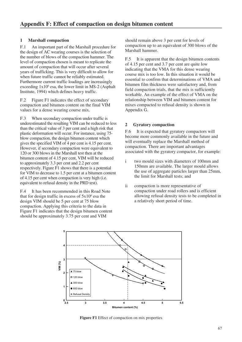
67
Appendix F: Effect of compaction on design bitumen content
should remain above 3 per cent for levels ofcompaction up to an equivalent of 300 blows of theMarshall hammer.
F.5 It is apparent that the design bitumen contentsof 4.15 per cent and 3.7 per cent are quite lowindicating that the VMA for this dense wearingcourse mix is too low. In this situation it would beessential to confirm that determinations of VMA andbitumen film thickness were satisfactory and, fromfield compaction trials, that the mix is sufficientlyworkable. An example of the effect of VMA on therelationship between VIM and bitumen content formixes compacted to refusal density is shown inAppendix G.
2 Gyratory compaction
F.6 It is expected that gyratory compactors willbecome more commonly available in the future andwill eventually replace the Marshall method ofcompaction. There are important advantagesassociated with the gyratory compactor, for example:
i two mould sizes with diameters of 100mm and150mm are available. The larger mould allowsthe use of aggregate particles larger than 25mm,the limit for Marshall tests; and
ii compaction is more representative ofcompaction under road rollers and is efficientallowing refusal density tests to be completed ina relatively short period of time.
1 Marshall compaction
F.1 An important part of the Marshall procedure forthe design of AC wearing courses is the selection ofthe number of blows of the compaction hammer. Thelevel of compaction chosen is meant to replicate theamount of compaction that will occur after severalyears of trafficking. This is very difficult to allow forwhen future traffic cannot be reliably estimated.Furthermore current traffic loadings are increasinglyexceeding 1x10⁶ esa, the lower limit in MS-2 (AsphaltInstitute, 1994) which defines heavy traffic.
F.2 Figure F1 indicates the effect of secondarycompaction and bitumen content on the final VIMvalues for a dense wearing course mix.
F.3 When secondary compaction under traffic isunderestimated the resulting VIM can be reduced to lessthan the critical value of 3 per cent and a high risk thatplastic deformation will occur. For instance, using 75-blow compaction, the design bitumen content whichgives the specified VIM of 4 per cent is 4.15 per cent.However, if secondary compaction were equivalent to120 or 300 blows in the Marshall test then at thebitumen content of 4.15 per cent, VIM will be reducedto approximately 3.3 per cent and 2.2 per centrespectively. Figure F1 shows that there is a potentialfor VIM to decrease to 1.5 per cent at a bitumen contentof 4.15 per cent when compaction is very high (i.e.equivalent to refusal density in the PRD test).
F.4 It has been recommended in this Road Notethat for design traffic in excess of 5x10⁶ esa thedesign VIM should be 5 per cent at 75 blowcompaction. Applying this criteria to the data inFigure F1 indicates that the design bitumen contentshould be approximately 3.75 per cent and VIM
Figure F1 Effect of compaction on mix properties
0
1
2
3
4
5
2.5 3 3.5 4 4.5 5 5.5
Bitumen content (%)
VIM
(%
)
75 blow
120 blow
300 blow
600 blow
Refusal Density
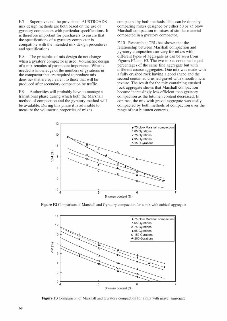
68
Figure F3 Comparison of Marshall and Gyratory compaction for a mix with gravel aggregate
Figure F2 Comparison of Marshall and Gyratory compaction for a mix with cubical aggregate
0
2
4
6
8
10
12
4 5 6 7
Bitumen content (%)
VIM
(%
)
75 blow Marshall compaction
65 Gyrations
75 Gyrations
95 Gyrations
150 Gyrations
F.7 Superpave and the provisional AUSTROADSmix design methods are both based on the use ofgyratory compactors with particular specifications. Itis therefore important for purchasers to ensure thatthe specifications of a gyratory compactor iscompatible with the intended mix design proceduresand specifications.
F.8 The principles of mix design do not changewhen a gyratory compactor is used. Volumetric designof a mix remains of paramount importance. What isneeded is knowledge of the numbers of gyrations inthe compactor that are required to produce mixdensities that are equivalent to those that will beproduced after secondary compaction by traffic.
F.9 Authorities will probably have to manage atransitional phase during which both the Marshallmethod of compaction and the gyratory method willbe available. During this phase it is advisable tomeasure the volumetric properties of mixes
compacted by both methods. This can be done bycomparing mixes designed by either 50 or 75 blowMarshall compaction to mixes of similar materialcompacted in a gyratory compactor.
F.10 Research at TRL has shown that therelationship between Marshall compaction andgyratory compaction can vary for mixes withdifferent types of aggregate as can be seen fromFigures F2 and F3. The two mixes contained equalpercentages of the same fine aggregate but withdifferent coarse aggregates. One mix was made witha fully crushed rock having a good shape and thesecond contained crushed gravel with smooth microtexture. The result for the mix containing crushedrock aggregate shows that Marshall compactionbecame increasingly less efficient than gyratorycompaction as the bitumen content decreased. Incontrast, the mix with gravel aggregate was easilycompacted by both methods of compaction over therange of test bitumen contents.
4 5 6 7
Bitumen content (%)
VIM
(%
)
75 blow Marshall compaction
65 Gyrations
75 Gyrations
95 Gyrations
150 Gyrations
0
2
4
6
8
10
12
14
200 Gyrations
69
Appendix G: Refusal density test using a vibrating hammer
points of a compass, the order should be N, S, W, E.NW, SE, SW, NE. At each point compaction shouldcontinue for between 2 and 10 seconds, the limitingfactor being that material should not be allowed to‘push up’ around the compaction foot. Thecompaction process is continued for a total of 2minutes ± 5 seconds. The large tamping foot is thenused to smooth the surface of the sample.
G.6 To ensure refusal density is achieved thecompaction process should then be repeatedimmediately on the other face of the sample. A sparebase-plate, previously heated in the oven, is placedon top of the mould which is then turned over. Thesample is driven to the new base plate with thehammer and large tamping foot. The compactionsequence is then repeated. The free base plate shouldbe returned to the oven between compaction cycles.
Compaction of cores to refusal densityG.7 Pre-construction field trials and subsequentmonitoring for quality control purposes will involvethe compaction to refusal of 150mm diameter corescut from the compacted surfacing in accordance withthe procedure given in BS 598: Part 104:1989. Insummary, any material from underlying layers shouldbe removed and the dimensions of the core measuredwith callipers. The core must then be dried at atemperature which does not cause distortion of thecore, but in any event the temperature must notexceed 45°C. Drying for 16 hours at 40°C isnormally sufficient to achieve constant mass. This isdefined as being a change in mass of no more than0.05% over a 2 hour period.
G.8 The core is then allowed to cool to ambienttemperature and weighed before determining its bulkdensity. When the core is permeable, which is likelyto be the case when samples are taken beforetrafficking, accurate measurement of bulk density isdifficult. BS 598: Part 104 gives the option of coatingthe core with wax. To make it easier to remove thewax after determining the core’s bulk density, it canbe cooled in a refrigerator and dusted with talcumpowder before waxing. The use of the physicalmeasurements of the core should be considered as anadditional or alternative procedure. However, severalaccurate measurements must be made on eachdimension. It is important that an agreed procedure isestablished at the start of a project.
G.9 After determination of its bulk density andremoval of any wax coating, the core is placed in asplit mould, heated to the appropriate testtemperature, as indicated in paragraph G4, andsubjected to refusal compaction as described in G5
1 Equipment
G.1 The equipment and the method of compactionused in the vibrating hammer test procedure forcompacting HMA to refusal density is based on thePercentage Refusal Density (PRD) test (BSI, 1989).
A minimum of 8 moulds and 9 base plates arerecommended for a refusal mix design. The completeequipment list is:
A tamping foot with a diameter of 102mm.
A tamping foot with a diameter of 146mm.
2 shanks for the tamping feet.
8 No. 152-153mm diameter split moulds.
9 No. base plates.
1 Vibrating hammer with a power consumptionof 750 watts or more, operating at a frequencyof 50 or 60 Hz.
The equipment can also be used for field control testing.
2 Vibrating hammer compaction
G.2 The refusal density test can be carried out on;
i mixes prepared in the laboratory;
ii hot mix sampled at the asphalt plant or on site;and
iii cores cut from the road.
Compaction of loose mix materialG.3 Trial samples should be made to determine themass of material required to give a compacted thicknesswhich is approximately the same as the layer to beconstructed. As discussed in Chapter 5, the selectedmaximum stone size in the mix may be influenced bythe thickness of the layer to be constructed.
G.4 The moulds, base plate and tamping footshould all be pre-heated and samples should bemixed so that they can be compacted immediately atan initial temperature of 140 ± 5°C for 80/100penetration grade bitumen and 145 ± 5°C for 60/70penetration grade bitumen.
G.5 The small tamping foot is used for most of thecompaction sequence. The hammer must be heldfirmly in a vertical position and moved from positionto position in the prescribed order, i.e. referring to the
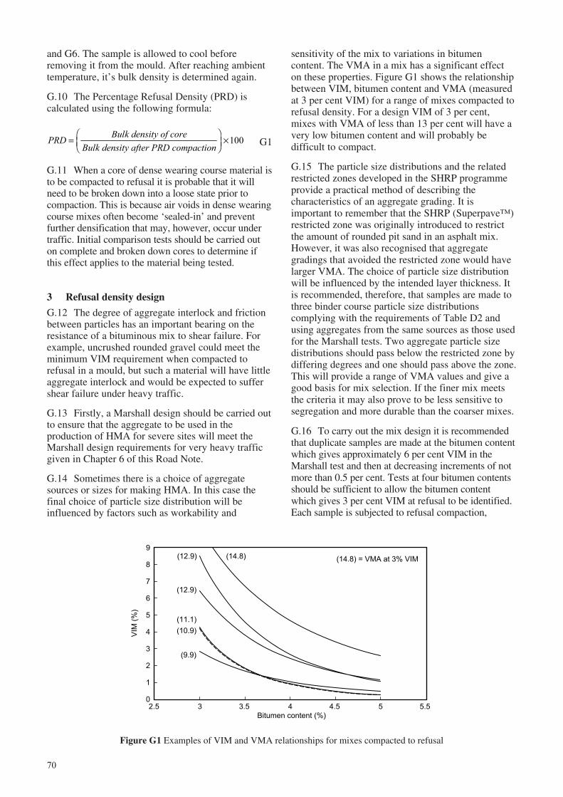
70
0
1
2
3
4
5
6
7
8
9
2.5 3 3.5 4 4.5 5 5.5
Bitumen content (%)
VIM
(%
)
(14.8) = VMA at 3% VIM
(9.9)
(10.9)
(11.1)
(12.9)
(12.9) (14.8)
Figure G1 Examples of VIM and VMA relationships for mixes compacted to refusal
and G6. The sample is allowed to cool beforeremoving it from the mould. After reaching ambienttemperature, it’s bulk density is determined again.
G.10 The Percentage Refusal Density (PRD) iscalculated using the following formula:
PRD =FHG
IKJ ×
Bulk density of coreBulk density after PRD compaction
100 G1
G.11 When a core of dense wearing course material isto be compacted to refusal it is probable that it willneed to be broken down into a loose state prior tocompaction. This is because air voids in dense wearingcourse mixes often become ‘sealed-in’ and preventfurther densification that may, however, occur undertraffic. Initial comparison tests should be carried outon complete and broken down cores to determine ifthis effect applies to the material being tested.
3 Refusal density design
G.12 The degree of aggregate interlock and frictionbetween particles has an important bearing on theresistance of a bituminous mix to shear failure. Forexample, uncrushed rounded gravel could meet theminimum VIM requirement when compacted torefusal in a mould, but such a material will have littleaggregate interlock and would be expected to suffershear failure under heavy traffic.
G.13 Firstly, a Marshall design should be carried outto ensure that the aggregate to be used in theproduction of HMA for severe sites will meet theMarshall design requirements for very heavy trafficgiven in Chapter 6 of this Road Note.
G.14 Sometimes there is a choice of aggregatesources or sizes for making HMA. In this case thefinal choice of particle size distribution will beinfluenced by factors such as workability and
sensitivity of the mix to variations in bitumencontent. The VMA in a mix has a significant effecton these properties. Figure G1 shows the relationshipbetween VIM, bitumen content and VMA (measuredat 3 per cent VIM) for a range of mixes compacted torefusal density. For a design VIM of 3 per cent,mixes with VMA of less than 13 per cent will have avery low bitumen content and will probably bedifficult to compact.
G.15 The particle size distributions and the relatedrestricted zones developed in the SHRP programmeprovide a practical method of describing thecharacteristics of an aggregate grading. It isimportant to remember that the SHRP (Superpave™)restricted zone was originally introduced to restrictthe amount of rounded pit sand in an asphalt mix.However, it was also recognised that aggregategradings that avoided the restricted zone would havelarger VMA. The choice of particle size distributionwill be influenced by the intended layer thickness. Itis recommended, therefore, that samples are made tothree binder course particle size distributionscomplying with the requirements of Table D2 andusing aggregates from the same sources as those usedfor the Marshall tests. Two aggregate particle sizedistributions should pass below the restricted zone bydiffering degrees and one should pass above the zone.This will provide a range of VMA values and give agood basis for mix selection. If the finer mix meetsthe criteria it may also prove to be less sensitive tosegregation and more durable than the coarser mixes.
G.16 To carry out the mix design it is recommendedthat duplicate samples are made at the bitumen contentwhich gives approximately 6 per cent VIM in theMarshall test and then at decreasing increments of notmore than 0.5 per cent. Tests at four bitumen contentsshould be sufficient to allow the bitumen contentwhich gives 3 per cent VIM at refusal to be identified.Each sample is subjected to refusal compaction,
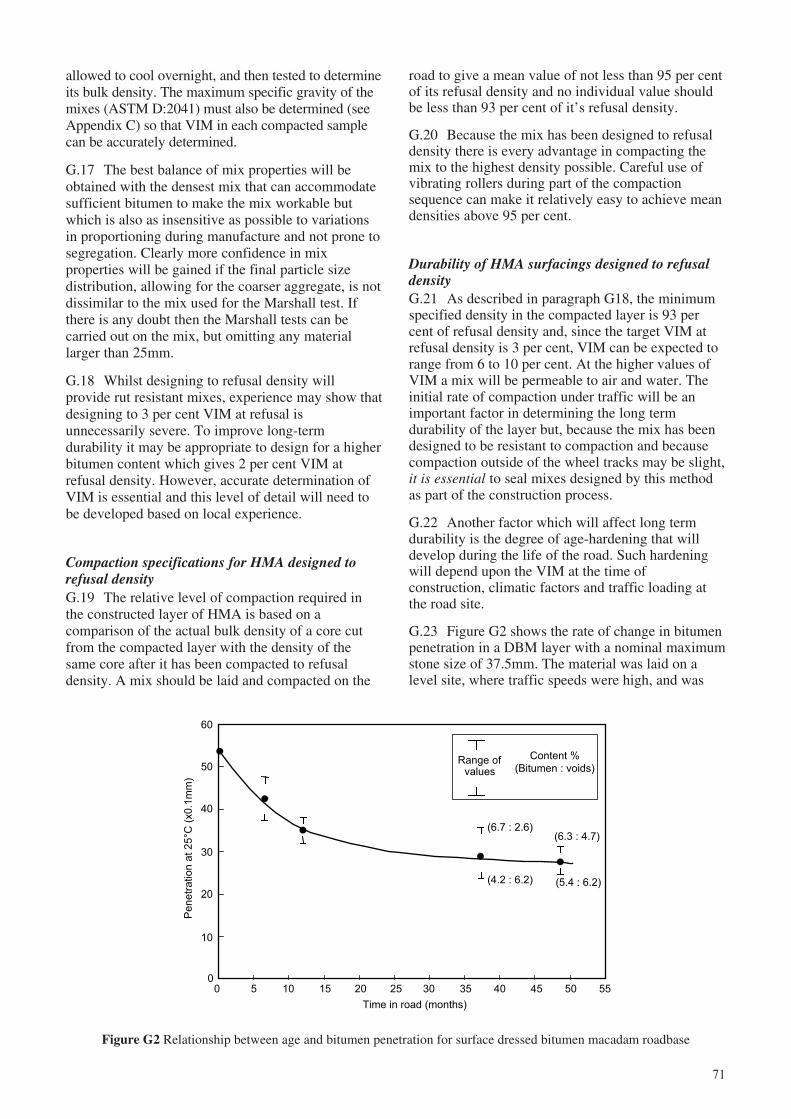
71
allowed to cool overnight, and then tested to determineits bulk density. The maximum specific gravity of themixes (ASTM D:2041) must also be determined (seeAppendix C) so that VIM in each compacted samplecan be accurately determined.
G.17 The best balance of mix properties will beobtained with the densest mix that can accommodatesufficient bitumen to make the mix workable butwhich is also as insensitive as possible to variationsin proportioning during manufacture and not prone tosegregation. Clearly more confidence in mixproperties will be gained if the final particle sizedistribution, allowing for the coarser aggregate, is notdissimilar to the mix used for the Marshall test. Ifthere is any doubt then the Marshall tests can becarried out on the mix, but omitting any materiallarger than 25mm.
G.18 Whilst designing to refusal density willprovide rut resistant mixes, experience may show thatdesigning to 3 per cent VIM at refusal isunnecessarily severe. To improve long-termdurability it may be appropriate to design for a higherbitumen content which gives 2 per cent VIM atrefusal density. However, accurate determination ofVIM is essential and this level of detail will need tobe developed based on local experience.
Compaction specifications for HMA designed torefusal densityG.19 The relative level of compaction required inthe constructed layer of HMA is based on acomparison of the actual bulk density of a core cutfrom the compacted layer with the density of thesame core after it has been compacted to refusaldensity. A mix should be laid and compacted on the
road to give a mean value of not less than 95 per centof its refusal density and no individual value shouldbe less than 93 per cent of it’s refusal density.
G.20 Because the mix has been designed to refusaldensity there is every advantage in compacting themix to the highest density possible. Careful use ofvibrating rollers during part of the compactionsequence can make it relatively easy to achieve meandensities above 95 per cent.
Durability of HMA surfacings designed to refusaldensityG.21 As described in paragraph G18, the minimumspecified density in the compacted layer is 93 percent of refusal density and, since the target VIM atrefusal density is 3 per cent, VIM can be expected torange from 6 to 10 per cent. At the higher values ofVIM a mix will be permeable to air and water. Theinitial rate of compaction under traffic will be animportant factor in determining the long termdurability of the layer but, because the mix has beendesigned to be resistant to compaction and becausecompaction outside of the wheel tracks may be slight,it is essential to seal mixes designed by this methodas part of the construction process.
G.22 Another factor which will affect long termdurability is the degree of age-hardening that willdevelop during the life of the road. Such hardeningwill depend upon the VIM at the time ofconstruction, climatic factors and traffic loading atthe road site.
G.23 Figure G2 shows the rate of change in bitumenpenetration in a DBM layer with a nominal maximumstone size of 37.5mm. The material was laid on alevel site, where traffic speeds were high, and was
Figure G2 Relationship between age and bitumen penetration for surface dressed bitumen macadam roadbase
Penetr
ation a
t 25°C
(x0.1
mm
)
Time in road (months)
60
50
40
30
20
10
00 10 15 20 25 30 35 40 45 50 555
(6.7 : 2.6)
(4.2 : 6.2)
(6.3 : 4.7)
(5.4 : 6.2)
Content %
(Bitumen : voids)Range of
values
72
surfaced with a Cape seal as part of the constructionprocess. The figure shows that even dense mixtureswith high bitumen content and low VIM can ageharden to penetrations of less than 30 within fouryears even when sealed. However, without the sealthe bitumen in the surface of the DBM layer wouldbecome very brittle and almost certainly suffer early‘top down’ cracking.
G.24 Where a surface dressing is to be applied itshould be constructed as soon as the surfacing is hardenough to prevent excessive embedment of thechippings into the layer. Because HMA designed torefusal density will have a high content of relativelycoarse aggregate it should be possible to construct asurface dressing soon after the HMA has beenconstructed. Surface hardness tests (TRL, 2000 orCOLTO, 1998) can be used to determine theoptimum time for sealing work. A slurry seal or Capeseal (a slurry seal on a single surface dressing) (TRL,2000, or COLTO, 1998) can also be used to surfacethe HMA layer.
4 Transfer of refusal density mix design tocompaction trials
G.25 Samples of binder course which have beencompacted from the loose state in the laboratory mayhave densities between 1.5% and 3% lower than forthe same material compacted in the road, cored andcompacted to refusal in the PRD test. This is anindication of the effect of the different compactionregimes which produce different orientations of theaggregate particles. Refusal densities of laboratory-compacted loose samples and of cores cut from thecompaction trials and then subjected to refusalcompaction should be compared to determine if thisdifference occurs. This will ensure that the densitiesof cores and loose material compacted in thelaboratory can be properly compared.
G.26 A minimum of three trial lengths should beconstructed with bitumen contents at the laboratoryoptimum (see paragraph G16 above) for refusaldensity (giving 3% VIM) and at 0.5% above andbelow the optimum. The trials should be used to;
i confirm that the mix is workable and can becompacted to a satisfactory density;
ii establish the best rolling patterns for theavailable road rollers; and
iii obtain duplicate sets of cores so that themaximum binder content which allows 3% VIMto be retained at refusal density can beconfirmed.
G.27 For a given level of compaction in theMarshall test, VMA decreases to a minimum andthen increases as bitumen content is increased.However, samples compacted to refusal density willusually have relatively constant values of VMA overa range of bitumen contents before the aggregatestructure begins to become ‘over filled’ and VMAincreases. This means that during the trials it will bea relatively simple matter to determine the sensitivityof the mix to variations in bitumen content and toconfirm the bitumen content required to give aminimum of 3% VIM at refusal density. If necessarythe aggregate grading can be adjusted to increaseVMA which will reduce the sensitivity of the mix.
G.28 A minimum of 93% and a mean value of 95%of refusal density are recommended as thespecification for field compaction of the layer. Fromthese trials and the results of the laboratory tests, it isthen possible to establish a job mix formula. Afterthis initial work, subsequent compliance testingbased on analysis of mix composition and refusaldensity should be quick, especially if fieldcompaction is monitored with a nuclear densitygauge. This initial procedure is time consuming but isjustified by the long term savings that can be madeby extending pavement service life and minimisingeventual rehabilitation costs.
73
Appendix H: Recycling of bituminous materials
bound material and it’s use as unbound materialshould be regarded as the minimum target forrecycling.
H.6 The decision to recycle asphalt, its appropriateuse and the quality that can be achieved, will bedetermined by a number of factors which include thefollowing:
i availability of suitable recycling plant;
ii the thickness of the existing bituminous layer;
iii the effect on traffic management, i.e. candeviations be constructed or must thecarriageway be partially open to traffic;
iv the level of quality control that can be achievedin the recycling process; and
v the variability in the properties of the existingmaterial.
H.7 Standard ‘cutting-out’ and crushing equipmentcan be very effective for producing well graded RAPfrom brittle age-hardened asphalt. This material,modified if necessary by the addition of freshaggregate, may be suitable for use in any pavementlayer. However, it is recommended that RAP is notused to manufacture bituminous wearing coursesunless it can be demonstrated that the high degree ofuniformity and the close tolerances required for thiscritical layer can be achieved. The wider tolerancesallowed for bituminous roadbase and, to a lesserextent, for binder courses, make these mixes moresuitable for incorporating RAP. The uniformity andquality of the RAP and the type of recycling plantwill determine the percentage of RAP that can beused in the mixes. Typically this will range from 20to 50 per cent.
H.8 When RAP is to be used in a pavement layer,good quality control of the RAP stockpiles will bevital to the manufacture of consistent HMA. Thismay require a considerable amount of testing. Thepresence of old multiple surface dressings may beacceptable if they have age-hardened. However,where there has been heavy patching or the quality ofthe seal is variable, recycling may be limited to insitu pulverisation and stabilisation.
H.9 Powerful pulverisers are available whichmakes it possible to carry out cold in situ recyclingwith fresh materials being incorporated as necessaryto produce a layer of the required quality.
1 Introduction
H.1 The use of thick bituminous surfacings indeveloping countries is increasing as traffic loadsincrease. When they become worn out the recyclingof such materials can reduce costs and damage to theenvironment by reducing the exploitation of localnatural resources. This is particularly true forcountries where there is a shortage of road-buildingaggregate or where there are no indigenous oilreserves.
H.2 It is possible to ensure that there are benefitsboth for client and contractor from recyclingoperations but recycling is unlikely to becomewidespread in developing countries until certainconditions are met. These include:
i sufficient potential for recycling to justify thepurchase of specialist plant;
ii pressure from government agencies toimplement recycling;
iii suitable specifications and/or workingmethodologies for contractual use; and
iv a good understanding of material properties andmethods of modification and application.
H.3 In tropical countries the types of asphalt thatare most likely to be available for recycling are thosethat have become severely age-hardened and crackedor surfacings that have failed through plasticdeformation. Of these types of failure the former ismore common, with plastic deformation failuresoccurring locally where traffic is slow moving suchas at junctions and on climbing lanes. Aged asphaltcan be expected to be brittle and to contain very hardbitumen. In contrast, asphalt that has deformedplastically is likely to contain bitumen that hassuffered very little age hardening. These two types ofmaterial present different problems for recovery,stockpiling and re-use.
2 Methods of recycling
H.4 Reclaimed Asphalt Pavement (RAP), ormillings, are primarily recycled in three ways. Theyare crushed and used as granular materials for fill orlower pavement layers or re-used in a bituminousmaterial, either by cold mix or hot mix recycling.These recycling processes can be carried out eitherin-place or at a central plant.
H.5 The greatest cost savings will be obtainedwhen RAP is used to produce good quality bitumen-
74
3 Suggested method of sampling existingasphalt
H.10 A feasibility study will be necessary to assessthe variability of the existing material, to establishthat a suitable mix design can be achieved, and that itcan be manufactured with the available plant. Duringthe feasibility study, samples must be cut from theexisting asphalt for analysis. A balance must befound between costly and time consuming testing andthe need for sufficient samples to determine materialvariability. The sampling pattern should take accountof visually obvious variability such as:
i contaminated ‘oil lanes’;
ii wheelpaths that look ‘rich’ in bitumen,indicating a dense material in which bitumenhardening may not be as severe as elsewhere inthe pavement;
iii material which looks rich in bitumen and mayhave deformed plastically; and
iv cracking or fretting indicating that appreciablebitumen hardening has occurred.
H.11 Identification of road lengths with apparentlyuniform appearance will help to establish shortrepresentative sections which can be tested. Based onthese sections a suitable pattern of testing can beestablished. The intention should be to stockpileseparately severely age-hardened materials, typicallywith penetration values of less than 20, from lesshardened materials and to discard badly contaminatedmaterial from ‘oil lanes’. Detailed assessment ofstockpile management should be finalised after adesk study has been carried out to show how thevarious RAP materials can be combined with freshaggregate to produce acceptable mixes.
H.12 The following tests should be carried out todetermine material properties:
i particle size distribution;
ii bitumen content;
iii viscosity of recovered bitumen; and
iv an assessment of crushability.
H.13 Recovering bitumen from RAP to determinethe penetration of the existing bitumen will present aproblem for many authorities. Unless it is clear thatthe existing bitumen is severely age hardened it islikely that a carefully selected batch of cores willhave to be sent to a qualified testing house to havethese tests carried out.
4 Methods of obtaining RAP
H.14 RAP can be obtained by milling or it can becut from the road in lumps which must be crushed.An assessment of the likelihood of obtaining a wellcrushed material with the available plant must bemade, preferably at the feasibility stage. Milling isparticularly useful where traffic access must beretained during the removal of damaged asphalt.Either method is suitable when the road is closed totraffic during the rehabilitation work.
Asphalt millingsH.15 Asphalt millings are obtained by planing, in alayer by layer fashion, using a mobile plant and aretypically consistent in their lump-size distribution.They can normally be used as granular material, aswon, or with minimum screening to remove anyover-size material.
Crushed asphaltH.16 Crushed asphalt is commonly obtained byusing horizontal impact crushers or hammermillimpact crushers. Jaw/roll combination crushers arenot suitable for processing RAP which contains ‘soft’bitumen because ‘pancaking’ can occur on warmdays and the material will remain agglomerated.
Granulated asphaltH.17 Granulated asphalt is produced in a specialisedplant, known as a granulator, or in milling/grindingunits. These units are not crushers and are designedonly to break the bitumen-asphalt bond.
5 Stockpiling RAP
H.18 The stockpiling of RAP is a very importantpart of the recycling process. The full benefits ofcomprehensive testing of the in situ asphalt layerscan easily be lost if equally meticulous control of thestockpiling process is not put in place. Dependingupon the variability found during testing, it may benecessary to build separate stockpiles of materialstaken from different sections of the road.
H.19 The tendency for RAP to agglomerate will beaffected by both the hardness of the bitumen in theRAP and the ambient temperature. The most effectivemethod of stockpiling must be established by trial anderror. Experience in the USA (NAPA, 1996) hasshown that RAP in large piles does not tend toagglomerate. A 250-300mm crust may form at thesurface of the stockpile and this should be scalped offand reprocessed prior to recycling. Higher stockpilesshould, therefore, provide more usable RAP.
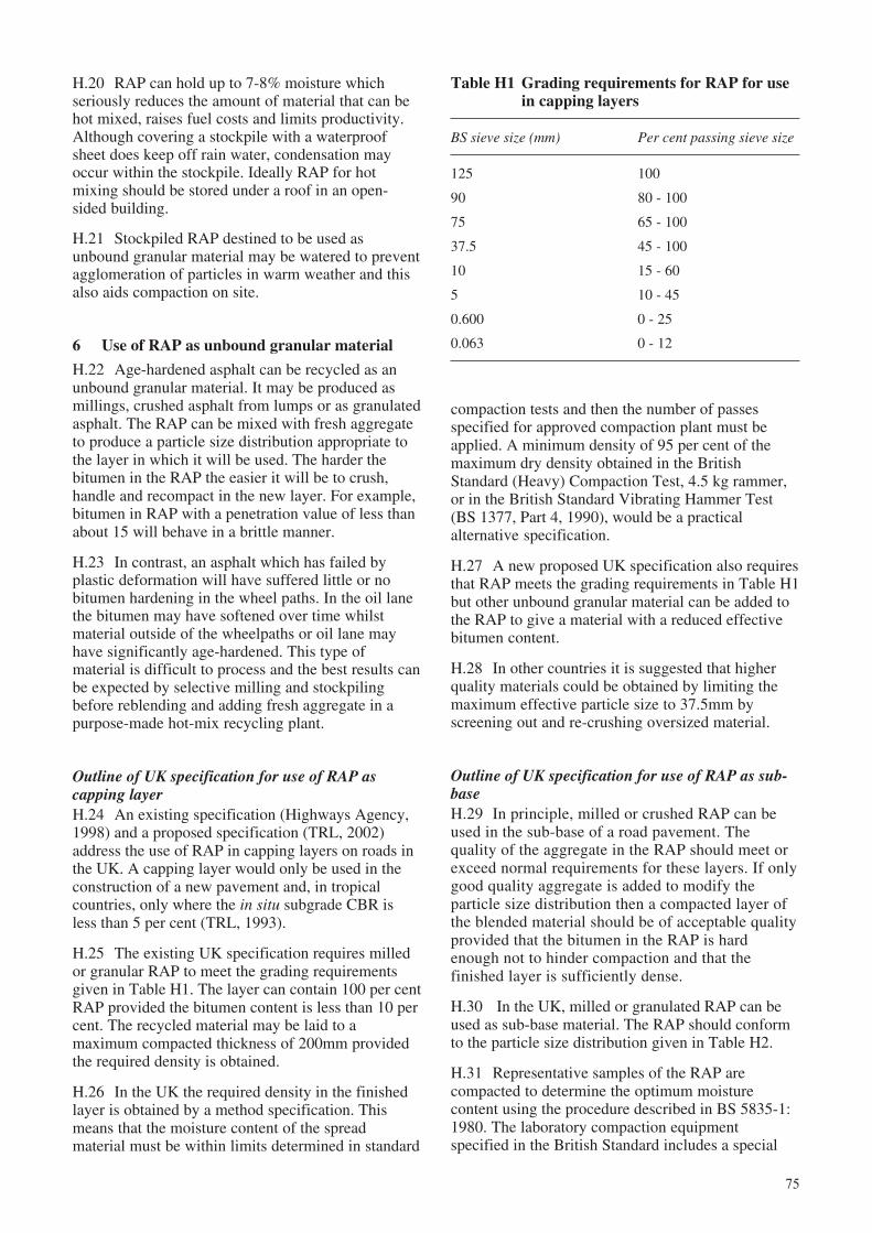
75
H.20 RAP can hold up to 7-8% moisture whichseriously reduces the amount of material that can behot mixed, raises fuel costs and limits productivity.Although covering a stockpile with a waterproofsheet does keep off rain water, condensation mayoccur within the stockpile. Ideally RAP for hotmixing should be stored under a roof in an open-sided building.
H.21 Stockpiled RAP destined to be used asunbound granular material may be watered to preventagglomeration of particles in warm weather and thisalso aids compaction on site.
6 Use of RAP as unbound granular material
H.22 Age-hardened asphalt can be recycled as anunbound granular material. It may be produced asmillings, crushed asphalt from lumps or as granulatedasphalt. The RAP can be mixed with fresh aggregateto produce a particle size distribution appropriate tothe layer in which it will be used. The harder thebitumen in the RAP the easier it will be to crush,handle and recompact in the new layer. For example,bitumen in RAP with a penetration value of less thanabout 15 will behave in a brittle manner.
H.23 In contrast, an asphalt which has failed byplastic deformation will have suffered little or nobitumen hardening in the wheel paths. In the oil lanethe bitumen may have softened over time whilstmaterial outside of the wheelpaths or oil lane mayhave significantly age-hardened. This type ofmaterial is difficult to process and the best results canbe expected by selective milling and stockpilingbefore reblending and adding fresh aggregate in apurpose-made hot-mix recycling plant.
Outline of UK specification for use of RAP ascapping layerH.24 An existing specification (Highways Agency,1998) and a proposed specification (TRL, 2002)address the use of RAP in capping layers on roads inthe UK. A capping layer would only be used in theconstruction of a new pavement and, in tropicalcountries, only where the in situ subgrade CBR isless than 5 per cent (TRL, 1993).
H.25 The existing UK specification requires milledor granular RAP to meet the grading requirementsgiven in Table H1. The layer can contain 100 per centRAP provided the bitumen content is less than 10 percent. The recycled material may be laid to amaximum compacted thickness of 200mm providedthe required density is obtained.
H.26 In the UK the required density in the finishedlayer is obtained by a method specification. Thismeans that the moisture content of the spreadmaterial must be within limits determined in standard
compaction tests and then the number of passesspecified for approved compaction plant must beapplied. A minimum density of 95 per cent of themaximum dry density obtained in the BritishStandard (Heavy) Compaction Test, 4.5 kg rammer,or in the British Standard Vibrating Hammer Test(BS 1377, Part 4, 1990), would be a practicalalternative specification.
H.27 A new proposed UK specification also requiresthat RAP meets the grading requirements in Table H1but other unbound granular material can be added tothe RAP to give a material with a reduced effectivebitumen content.
H.28 In other countries it is suggested that higherquality materials could be obtained by limiting themaximum effective particle size to 37.5mm byscreening out and re-crushing oversized material.
Outline of UK specification for use of RAP as sub-baseH.29 In principle, milled or crushed RAP can beused in the sub-base of a road pavement. Thequality of the aggregate in the RAP should meet orexceed normal requirements for these layers. If onlygood quality aggregate is added to modify theparticle size distribution then a compacted layer ofthe blended material should be of acceptable qualityprovided that the bitumen in the RAP is hardenough not to hinder compaction and that thefinished layer is sufficiently dense.
H.30 In the UK, milled or granulated RAP can beused as sub-base material. The RAP should conformto the particle size distribution given in Table H2.
H.31 Representative samples of the RAP arecompacted to determine the optimum moisturecontent using the procedure described in BS 5835-1:1980. The laboratory compaction equipmentspecified in the British Standard includes a special
Table H1 Grading requirements for RAP for usein capping layers
BS sieve size (mm) Per cent passing sieve size
125 100
90 80 - 100
75 65 - 100
37.5 45 - 100
10 15 - 60
5 10 - 45
0.600 0 - 25
0.063 0 - 12
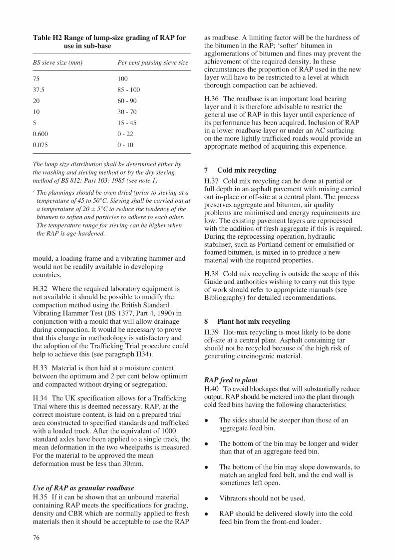
76
Table H2 Range of lump-size grading of RAP foruse in sub-base
BS sieve size (mm) Per cent passing sieve size
75 100
37.5 85 - 100
20 60 - 90
10 30 - 70
5 15 - 45
0.600 0 - 22
0.075 0 - 10
The lump size distribution shall be determined either bythe washing and sieving method or by the dry sievingmethod of BS 812: Part 103: 1985 (see note 1)
1 The plannings should be oven dried (prior to sieving at atemperature of 45 to 50°C. Sieving shall be carried out ata temperature of 20 ± 5°C to reduce the tendency of thebitumen to soften and particles to adhere to each other.The temperature range for sieving can be higher whenthe RAP is age-hardened.
mould, a loading frame and a vibrating hammer andwould not be readily available in developingcountries.
H.32 Where the required laboratory equipment isnot available it should be possible to modify thecompaction method using the British StandardVibrating Hammer Test (BS 1377, Part 4, 1990) inconjunction with a mould that will allow drainageduring compaction. It would be necessary to provethat this change in methodology is satisfactory andthe adoption of the Trafficking Trial procedure couldhelp to achieve this (see paragraph H34).
H.33 Material is then laid at a moisture contentbetween the optimum and 2 per cent below optimumand compacted without drying or segregation.
H.34 The UK specification allows for a TraffickingTrial where this is deemed necessary. RAP, at thecorrect moisture content, is laid on a prepared trialarea constructed to specified standards and traffickedwith a loaded truck. After the equivalent of 1000standard axles have been applied to a single track, themean deformation in the two wheelpaths is measured.For the material to be approved the meandeformation must be less than 30mm.
Use of RAP as granular roadbaseH.35 If it can be shown that an unbound materialcontaining RAP meets the specifications for grading,density and CBR which are normally applied to freshmaterials then it should be acceptable to use the RAP
as roadbase. A limiting factor will be the hardness ofthe bitumen in the RAP; ‘softer’ bitumen inagglomerations of bitumen and fines may prevent theachievement of the required density. In thesecircumstances the proportion of RAP used in the newlayer will have to be restricted to a level at whichthorough compaction can be achieved.
H.36 The roadbase is an important load bearinglayer and it is therefore advisable to restrict thegeneral use of RAP in this layer until experience ofits performance has been acquired. Inclusion of RAPin a lower roadbase layer or under an AC surfacingon the more lightly trafficked roads would provide anappropriate method of acquiring this experience.
7 Cold mix recycling
H.37 Cold mix recycling can be done at partial orfull depth in an asphalt pavement with mixing carriedout in-place or off-site at a central plant. The processpreserves aggregate and bitumen, air qualityproblems are minimised and energy requirements arelow. The existing pavement layers are reprocessedwith the addition of fresh aggregate if this is required.During the reprocessing operation, hydraulicstabiliser, such as Portland cement or emulsified orfoamed bitumen, is mixed in to produce a newmaterial with the required properties.
H.38 Cold mix recycling is outside the scope of thisGuide and authorities wishing to carry out this typeof work should refer to appropriate manuals (seeBibliography) for detailed recommendations.
8 Plant hot mix recycling
H.39 Hot-mix recycling is most likely to be doneoff-site at a central plant. Asphalt containing tarshould not be recycled because of the high risk ofgenerating carcinogenic material.
RAP feed to plantH.40 To avoid blockages that will substantially reduceoutput, RAP should be metered into the plant throughcold feed bins having the following characteristics:
! The sides should be steeper than those of anaggregate feed bin.
! The bottom of the bin may be longer and widerthan that of an aggregate feed bin.
! The bottom of the bin may slope downwards, tomatch an angled feed belt, and the end wall issometimes left open.
! Vibrators should not be used.
! RAP should be delivered slowly into the coldfeed bin from the front-end loader.
77
! The level in the bin should be kept fairly low.This means that the bin must be fed morefrequently than is necessary for a normalaggregate cold feed bin.
! Material should not be left in the cold feed binfor more than one hour. It is more economical torun out the contents of the bin than to clear itsome time later.
Batch plant recyclingH.41 Because cold aggregate travels towards theheating flame in this type of plant the introduction ofRAP would result in excessive smoke and otherproblems. The technique of conductive heat transfer,which involves the super heating of fresh aggregateand adding cold RAP via the elevator or directly intothe weigh hopper minimises the likelihood of airpollution. The percentage of RAP that can be useddepends upon the following factors:
! The temperature to which the virgin aggregate isheated.
! The temperature and moisture content of the RAP.
! The required temperature of the final mix.
Under ideal conditions, batch plant recycling canblend up to 40 per cent RAP with superheated freshaggregate but 15 to 25 per cent is more typical.
Batch mixers with a separate heating drum (paralleldrum)H.42 In this system RAP is heated in a separatedrum to about 130ºC. Fresh aggregate is separatelyheated to a high temperature and both materials areweighed to produce the required blend in the mixingunit. The final temperature of the blend is about 160ºC. Preheating allows 50 per cent of RAP to be used inthe blend, or even more if a consistent quality ofoutput can be guaranteed.
H.43 Preheating the RAP allows the production of amore uniform mix and better control of mixtemperature and this is the preferred method ofrecycling. However, development continues and othertypes of plant specifically designed for recyclingbituminous materials are becoming available.
9 Evaluation and design - plant hot-mixrecycling
Variability of RAPH.44 As discussed in paragraphs H3 and H10, intropical countries, RAP will usually either bematerial which has failed by plastic deformation, and
will contain mostly relatively soft bitumen, or badlycracked asphalt containing very hard bitumen. It istherefore important to determine the variations inproperties of the bitumen in RAP and how this willbe taken into account in the mix design process.
10 Bitumen rejuvenators
H.45 Rejuvenators have been used to change theproperties of bitumen in RAP to those similar to newbitumen. Holmgreen (1980), however, discoveredthat although such agents could change aged bitumento the required viscosity, different agents producedbinders with different temperature susceptibilities. Itwas also found that there could be problems relatingto the compatibility between aged bitumen and therejuvenating agent (see also Kallas (1984)).
11 Blending with a soft bitumen
H.46 If a softer bitumen is added with the intentionof bringing the blended bitumen within specification,the penetration (P) of the fresh bitumen can becalculated using equation H1 (Whiteoak, 1990):
LogP A Pa B Pb= +log log100
H1
where, P = specified penetration of finalblend.
Pa = penetration of RAP bitumen.
Pb = penetration of virgin bitumen.
A = percentage of RAP bitumen in thefinal blend.
B = percentage of virgin bitumen inthe final blend.
In this relationship the ‘blend’ is the total quantity ofbitumen only, i.e. A+B = 100.
Limitations of bitumen blendingH.47 Bitumen in RAP recovered from a crackedasphalt will typically have a penetration of less than15 and satisfactory blending of the new and oldbitumen cannot be expected. For example, to obtain afinal penetration of 80 in a blend of 60 per cent offresh bitumen and 40 per cent RAP bitumen in whichthe bitumen had hardened to a penetration of 15,would require the use of a fresh bitumen with apenetration of approximately 200. It is highly likelythat some fresh aggregate would only be coated withthe soft fresh bitumen and this could play a dominantrole in mix performance with a risk of failure throughplastic deformation.
H.48 The most reliable method of obtaining a robustdesign with brittle asphalt is, therefore, to regard the
78
Table H3 Locations of core sampling
Between Vergev/s w-path side Centre- Off side
Chainage and road wheel line wheel(m) edge path of lane path
1000 ✓ ✓ ✓ ✓
900 ✓
800 ✓ ✓ ✓ ✓
700 ✓
600 ✓ ✓ ✓ ✓
500 ✓
400 ✓ ✓ ✓ ✓
300 ✓
200 ✓ ✓ ✓ ✓
100 ✓
0 ✓ ✓ ✓ ✓
bitumen in hardened RAP as being part of theaggregate structure and to use a 60/70 or 80/100penetration grade bitumen, rather than a soft binder.This will prevent the possibility of plasticdeformation in the new mix.
H.49 In the case of RAP from areas of plasticdeformation the effect of the softer existing bitumencan be taken into account during the mix designprocess. Testing of laboratory and plant mix asphaltto ensure that requirements for volumetric design andMarshall properties are met, will be required just asfor new material and therefore the Marshallprocedures outlined in Appendix C should befollowed. Additional information from a performancetest such as the wheel tracking test will also be veryhelpful in this evaluation.
H.50 The percentage of RAP that can be used willbe controlled by the mixing temperature that can beachieved in the blended material. The temperaturemust be high enough to ensure that the fresh bitumenis at a suitable viscosity for mixing.
12 Mix design
H.51 The most common design procedure usedoutside Europe is that proposed by the AsphaltInstitute (1986). In order to meet mix consistency anddesign tolerances it is recommended that RAP beused to produce binder course or roadbase mixes forwhich suitable specifications have been given inChapter 5 of this Road Note. These recycledmaterials must be sealed or surfaced with a newbituminous wearing course.
H.52 Initial assessments of the suitability ofmaterials for recycling may necessarily be based onthe results of tests carried out on completely ‘brokendown’ cores. In practice RAP would be obtained withheavy equipment producing blocks of material forcrushing or by use of a milling machine and thereforethe actual grading of the RAP must be taken intoaccount when completing the final mix designs. Theneed for further fine adjustment may be indicatedafter the handling and compaction characteristics ofthe new mix have been assessed in pre-constructiontrials because further breakdown of RAP is likely tohave occurred during plant mixing.
H.53 The recycled mix must meet the normalrequirements for volumetric composition, i.e. bedesigned to 4 or 5 per cent VIM and retain at least 3per cent VIM after secondary compaction by traffic asappropriate (see Appendix C). It will not be possible totest roadbase or binder course mixes by the Marshallmethod if they contain aggregate particles larger than25mm. If the proportion of material greater than25mm is small then the guidance given in paragraphs6.14 to 6.15 of this Road Note can be adopted and theresultant mix evaluated in field trials.
H.54 Where it is not possible to use the Marshalltest because of aggregate size, the PercentageRefusal Test (BSI, 1989) can be used to ensure thata suitable balance between composition andminimum VIM, after compaction, is obtained (seeAppendix G). The Percentage Refusal Density Testshould be used to check the density of the laidmaterial.
H.55 Aggregate used in the RAP may be known togive good Marshall test results when used in a newAC material. If the fresh aggregate also comes fromthe same or a similar rock source and meets thenormal requirements for aggregate soundness,strength and durability then compositional tests maybe sufficient for the design of an asphalt which willperform well under a new asphalt wearing course.However, wherever possible, performance tests suchas Indirect Tensile or wheel tracking tests, should beused to ensure that a satisfactory mix can beproduced.
13 Recycling feasibility studies
H.56 Two feasibility studies for recyclingbituminous surfacing materials are described below.Only core samples could be obtained for testing.Coring locations were established on 1km longsections which were representative of the remainderof the road. Both sections were visually reasonablyuniform. A longitudinal and transverse samplingpattern was adopted as shown in Table H3. Sitedetails are given in Table H4.
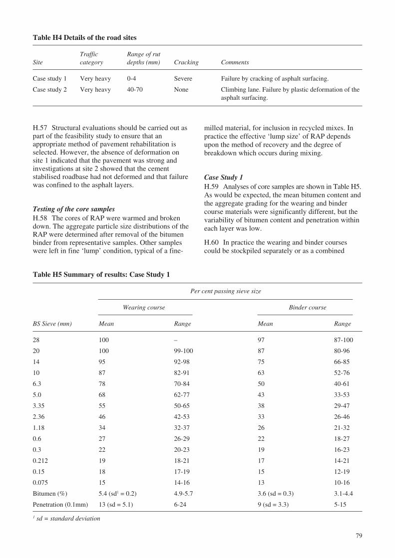
79
H.57 Structural evaluations should be carried out aspart of the feasibility study to ensure that anappropriate method of pavement rehabilitation isselected. However, the absence of deformation onsite 1 indicated that the pavement was strong andinvestigations at site 2 showed that the cementstabilised roadbase had not deformed and that failurewas confined to the asphalt layers.
Testing of the core samplesH.58 The cores of RAP were warmed and brokendown. The aggregate particle size distributions of theRAP were determined after removal of the bitumenbinder from representative samples. Other sampleswere left in fine ‘lump’ condition, typical of a fine-
Table H4 Details of the road sites
Traffic Range of rutSite category depths (mm) Cracking Comments
Case study 1 Very heavy 0-4 Severe Failure by cracking of asphalt surfacing.
Case study 2 Very heavy 40-70 None Climbing lane. Failure by plastic deformation of theasphalt surfacing.
milled material, for inclusion in recycled mixes. Inpractice the effective ‘lump size’ of RAP dependsupon the method of recovery and the degree ofbreakdown which occurs during mixing.
Case Study 1H.59 Analyses of core samples are shown in Table H5.As would be expected, the mean bitumen content andthe aggregate grading for the wearing and bindercourse materials were significantly different, but thevariability of bitumen content and penetration withineach layer was low.
H.60 In practice the wearing and binder coursescould be stockpiled separately or as a combined
Table H5 Summary of results: Case Study 1
Per cent passing sieve size
Wearing course Binder course
BS Sieve (mm) Mean Range Mean Range
28 100 – 97 87-100
20 100 99-100 87 80-96
14 95 92-98 75 66-85
10 87 82-91 63 52-76
6.3 78 70-84 50 40-61
5.0 68 62-77 43 33-53
3.35 55 50-65 38 29-47
2.36 46 42-53 33 26-46
1.18 34 32-37 26 21-32
0.6 27 26-29 22 18-27
0.3 22 20-23 19 16-23
0.212 19 18-21 17 14-21
0.15 18 17-19 15 12-19
0.075 15 14-16 13 10-16
Bitumen (%) 5.4 (sd1 = 0.2) 4.9-5.7 3.6 (sd = 0.3) 3.1-4.4
Penetration (0.1mm) 13 (sd = 5.1) 6-24 9 (sd = 3.3) 5-15
1 sd = standard deviation
80
Table H6 An example of blending fresh aggregate and RAP: Case Study 1
Superpave™ particle size distribution limits
Control points Blend 40%Restricted RAP and fresh
Min Max zone aggregate
Sieve size (mm) Per cent passing sieve size
37.5 100 – – 100
25 90 100 – 97
19 – 90 – 87
4.75 39.5/39.5 33
2.36 19 45 26.8/30.8 23
1.18 18.1/24.1 17
0.6 13.6/17.6 13
0.3 11.4/11.4 10
0.075 1 7 – 7
material. Milling would enable separate stockpilingbut if simple breaking out equipment were to be usedthen the two materials would probably be recoveredin large lumps which would have to be crushed andmixed to give a single RAP material.
H.61 In this case study the penetration of thebitumen in both layers was less than 15 and the RAPwas brittle. It is likely that full-scale recovery of RAPwould result in lumps containing material from bothlayers and the core samples were, therefore, mixedtogether for testing in the laboratory.
Use as granular materialH.62 Crushing and stockpiling RAP from this sitewould be relatively easy if the two layers of brittleasphalt were to be combined. An ‘all-in’ particle sizedistribution would easily meet the requirements givenin Table H2 for sub-base.
H.63 Clearly, thorough pre-crushing of the RAPwould make it easier to place and compact the materialand vibratory rollers should also be effective inbreaking down agglomerations. Fresh aggregate could,if necessary, be blended with the RAP to modify theparticle size distribution. The selection of an effectiveblend of materials must be determined after sufficientfield compaction trials have been carried out to ensurethat the normal requirements for the density andstrength of a sub-base have been achieved.
Hot mix recyclingH.64 During hot mix recycling, agglomeratedasphalt remaining in the pre-crushed RAP tends tobreakdown and the effective particle size distribution
of the RAP will be similar to that used in thelaboratory trials described below.
H.65 Reference to historical data for fresh aggregatestockpiles used on a local road contract showed thatup to 47 per cent of RAP could be blended with thesematerials to produce a grading meeting a roadbasespecification.
H.66 As indicated in Table H5, the penetration ofrecovered bitumen ranges from 6 to 24 in the wearingcourse and from 5 to 15 in the binder course. It isvery unlikely that a rejuvenator would suitablymodify the bitumen and it would be better to treat theexisting bitumen as part of the aggregate particlesand to add new 60/70 penetration bitumen.
H.67 A blend of 40 per cent RAP and freshaggregate was designed to conform with aSuperpave™ mix having a nominal maximumaggregate size of 25mm as shown in Table H6. It canbe seen that the particle size distribution passesbelow the restricted zone. The particle sizedistribution also conforms to the requirements of theAsphalt Institute for a nominal 25mm mix and theresultant mix should, therefore, have the potential tobe very stable.
H.68 Mix design was based on the bitumen contentwhich gave 3 per cent VIM at refusal density using avibrating hammer. The design bitumen content wasfound to be 2.8 per cent of fresh 60/70 penetrationgrade bitumen. Samples having a diameter of 150mmwere made in a gyratory compactor to giveapproximately 7 per cent VIM, or 96 per cent ofrefusal density, for Indirect Tensile Tests (ITT) andwheel tracking tests.
81
H.69 The results of the performance tests summarisedin Table H7 show that the mix should be very stableunder traffic. Wheel tracking tests, in particular, showthat the UK specification for ‘Very heavily stressedsites’ (see Appendix E) are easily met.
Case Study 2H.70 Plastic deformation of up to 70mm haddeveloped at this site. The appearance of the asphaltexposed at the sides of the cores was very uniformthroughout the depth of the material and noindividual layers could be identified. Asphaltthicknesses are summarised in Table H8.
H.71 Because of the large deformation it isconvenient to refer to the position of material inrelation to the top of the stabilised roadbase. Thecores were sawn into 50mm slices and bitumencontent, bitumen penetration and particle sizedistributions were carried out on the slices. Materialin layer 3 represented the top 50mm of the roadsurfacing. A summary of the results are given inTables H9 and H10.
H.72 The results show that layer 1 (immediately abovethe roadbase) had a slightly coarser particle sizedistribution and a mean bitumen content that was 0.4and 0.2 per cent lower than for layers 2 and 3
Table H9 VIM and bitumen content results: Case Study 2
Bitumen content (%)Height above No. cores No. with
Layer roadbase (mm) analysed VIM <3% Mean SD Range
1 0 - 50 16 11 4.1 0.3 3.2 - 4.6
2 51 - 100 16 16 4.5 0.4 3.6 - 5.0
3 101 - 150 10 10 4.3 0.4 3.7 - 5.0
Table H7 Laboratory performance test results for a recycled mix: Case Study 1
% of ITT (GPa)refusal Wheeltracking rate
No samples VIM (%) density (mm/hr at 60ºC) At 20ºC At 30ºC
6 per test 6.5-7.3 95.3-96.0 0.17-0.42 5.7-8.0 2.5-3.6
Table H8 Thicknesses of cores: Case Study 2
Core thicknesses (mm)
Near road Verge-side CentreChainage (m) Core Nos. edge wheelpath of lane Offside
0 1 145
100 2 - 5 190 107 175 115
200 6 106
300 7 – 10 135 143 145 112
400 11 93
500 12 - 15 157 113 175 78
600 16 132
700 17 - 20 148 155 120 150
800 21 95
900 22 –25 145 105 140 85
1000 26 107
82
Table H10 Aggregate particle size distributions: Case Study 2
Percent passing sieve size
Layer 1 Layer 2 Layer 3
BS Sieve (mm) Mean Range Mean Range Mean Range
28 97 91-100 99 96-100 100 –
20 84 70-92 98 86-97 98 94-100
14 70 56-87 80 73-87 89 82-96
10 60 44-74 70 64-75 75 67-85
6.3 51 35-63 60 53-65 60 53-73
5 45 31-58 53 46-60 54 47-65
3.35 40 27-51 47 42-54 48 40-54
2.36 34 23-44 42 37-46 42 35-47
1.18 26 18-34 33 26-46 34 27-38
0.6 22 15-28 28 21-35 29 24-33
0.3 17 12-23 23 16-29 24 18-28
0.212 14 10-19 20 13-25 21 15-25
0.15 11 7-15 16 9-21 18 12-22
0.075 7 5-11 11 5-15 13 7-17
respectively. Large variations were found in thepenetration of bitumen recovered from the three layers.Theoretical penetrations of fully blended RAP bitumenand fresh 65 and 100 penetration bitumens calculatedusing equation H1 are summarised in Table H11.
H.73 Bitumen in layer 1 had a much lowerpenetration than that in layers 2 and 3 indicating thatconsistent stockpiles of RAP would be obtained ifthis layer was treated separately. If 30 per cent ofRAP from layer 1 was recycled with fresh aggregateand 100 penetration grade bitumen then substitutionof these values in equation H1 indicates that theresultant penetration would be between 53 and 83with a median value of 66 if full blending of thebitumens occurred.
H.74 A satisfactory mix could probably be madeusing 30 per cent of well mixed RAP from layers 2and 3 blended with fresh aggregate and 65 penetrationgrade bitumen. Although it is very unlikely thatuniform blending of the bitumens would be achievedthe theoretical penetration of the blended bitumens,before ageing in the mixing process, would range fromapproximately 49 to 81 with a mean value of 66.
Reclaiming the existing asphaltH.75 It would be necessary to use a milling machineto produce as fine a material grading as possiblebecause the bitumen in the RAP is soft and simplecrushing during hot weather would probably not bepossible. Hot mixing would take advantage of the‘soft’ bitumen and the addition of fresh 60/70 or 80/
83
Table H13 Laboratory performance test results for a recycled mix: Case Study 2
% of refusal Wheeltracking rate ITT (GPa)No samples VIM (%) density (mm/hr at 60ºC) At 20ºC At 30ºC
6 per test " 7 96.0 0.12-0.46 – 1-2
Table H11 Penetration of bitumen in RAP and when fully blendedwith fresh bitumen: Case Study 2
Penetration of Penetration if fullyRAP bitumen Ratio RAP Penetration blended after mixing
to fresh of freshLayer Median Range aggregate bitumen Range Median
3. Top 50mm 87 30-135 30:70 52-81 6750:50 52-93 69
2. Middle 50mm 68 25-160 30:70 49-81 6450:50 65 40-94 65
1. Bottom 50mm 27 12-58 30:70 39-61 4950:50 28-59 41
3. Top 50mm 87 30-135 30:70 70-109 9050:50 55-115 86
2. Middle 50mm 68 25-160 30:70 66-109 8750:50 100 50-116 81
1. Bottom 50mm 27 12-58 30:70 53-83 6650:50 35-73 50
Table H12 An example of blending freshaggregate and RAP: Case Study 2
Passing sieve size (%)
Asphalt Institute particle BlendSieve size distribution for 25mm 50:50 RAPsize nominal maximum and fresh(mm) size aggregate aggregate
37.5 100 100
25 90 - 100 93
12.5 56 - 80 66
4.75 29 - 59 34
2.36 19 - 45 22
0.300 5 - 17 12
0.075 1 - 7 6

84

A g
uid
e to
th
e d
esig
n o
f h
ot
mix
asp
hal
t in
tro
pic
al a
nd
su
b-t
rop
ical
co
un
trie
sO
RN
19ISSN 0951-8797
OS-E


