August 2011 Oct 2011 16/06/2015 Oversteer / Understeer Objective measurement of tyre oversteer using VBOX equipment Abstract An important part of tyre testing is the measurement of tyre performance in respect to oversteer and under steer. Over or Understeer results from a number of factors including cornering speed, throttle, and steering input. To make an objective assessment of a tyre’s predisposition to over or understeer, those factors need to be monitored and kept constant. Measuring oversteer and understeer Oversteer occurs when the rear tyres lose lateral traction before the front tyres and the car starts to spin. This is when the car’s rear wheels lose grip through a corner. Understeer occurs when the front tyres lose lateral traction causing the front end to push towards the outside of the corner and for the steering to become useless. To measure over and understeer you will need to measure tyre slip angle at each tyre. Oversteer = Rear tyre slip angle > Front tyre slip angle Understeer = Front tyre slip angle > Rear tyre slip angle Slip Angle – what is it? In basic terms, slip angle is the difference between the direction a vehicle is travelling (known as heading or course over ground) and the direction that the body of the vehicle is pointing (true heading). For example, in the picture on the left, we can see that the vehicle is oversteering through the curve and is travelling generally in the direction of the front wheels, but the body of the vehicle is pointing towards the inner radius of the curve. True Heading Course over Ground Slip Angle Slip angle is then the difference between the true heading and the course over ground heading.
Transcript
August 2011
Oct 2011
16/06/2015
Oversteer / Understeer Objective measurement of tyre oversteer using VBOX equipment
Abstract An important part of tyre testing is the measurement of tyre performance in respect to oversteer and under steer. Over or Understeer results from a number of factors including cornering speed, throttle, and steering input.
To make an objective assessment of a tyre’s predisposition to over or understeer, those factors need to be monitored and kept constant.
Measuring oversteer and understeer
Oversteer occurs when the rear tyres lose lateral traction before the front tyres and the car starts to spin. This is when the car’s rear wheels lose grip through a corner.
Understeer occurs when the front tyres lose lateral traction causing the front end to push towards the outside of the corner and for the steering to become useless.
To measure over and understeer you will need to measure tyre slip angle at each tyre.
Oversteer = Rear tyre slip angle > Front tyre slip angle Understeer = Front tyre slip angle > Rear tyre slip angle
Slip Angle – what is it?
In basic terms, slip angle is the difference between the direction a vehicle is travelling (known as heading or course over ground) and the direction that the body of the vehicle is pointing (true heading).
For example, in the picture on the left, we can see that the vehicle is oversteering through the curve and is travelling generally in the direction of the front wheels, but the body of the vehicle is pointing towards the inner radius of the curve.
True Heading
Course over Ground
Slip Angle
Slip angle is then the difference between the true heading and the course over ground heading.
August 2011
Oct 2011
16/06/2015
Oversteer / Understeer Objective measurement of tyre oversteer using VBOX equipment
Measuring Body Slip Angle
The VBOX uses two antennas to measure slip angle – one designated as the primary antenna and one designated as the secondary antenna. The antennas are placed on the vehicle at a set distance apart, 2m for example. The VBOX uses the data from both antennas to calculate the true heading (a straight line through the antennas).
The greater the separation between the antennas, the more accurate the measurement of slip angle will be.
Maximum separation is 5m for a VBOX II SX Dual Antenna (VB20SL) and 10m for a VBOX 3i Dual Antenna (VB3iSL).
The VBOX also measures the GPS heading at the primary antenna (course over ground heading).
Slip angle is then the difference between the true heading and the course over ground heading, as shown in the picture above.
But slip angle is different at different points on the vehicle!
It is clear that the direction in which the body of vehicle is pointing is the same at all points of the vehicle, unless the vehicle is articulated.
The picture on the first page shows a vehicle which has lost traction at the rear wheels and is sliding around the corner – in this instance, the slip angle will be the same wherever it is measured at the rear of the the vehicle.
However, slip angle does not just occur when traction is lost – any turning manoeuvre will generate a level of slip angle. The vehicle will still have a true heading and a course over ground, but the ‘Course over Ground’ heading of a vehicle is different depending upon where on the vehicle it is measured. On any vehicle, the ‘Course over Ground heading of a point at the front of the vehicle will be different to that at the back of the vehicle during a turning manoeuvre, regardless of whether the vehicle is sliding or not as detailed in the diagram on the following page.
As we can see from the diagram on the left, the further forward the primary antenna is placed on the vehicle, the greater the effect the angle of the steered wheels has on the measurement of slip angle.
If we were to place the primary antenna over the steered wheels themselves, the measured slip angle would be almost identical to the wheels steering angles, less a small amount of tyre slip.
Normal Turning Manoeuvre
August 2011
Oct 2011
16/06/2015
Oversteer / Understeer Objective measurement of tyre oversteer using VBOX equipment
However, the steered wheels would need to be measured independently, due to the effects of Ackerman steering.
During a turning manoevre with oversteer (diagram on the right), the slip angle measured at the rear of the car is now showing a larger slip angle. The slip angles measured at the middle and front of the car in this case are now reduced, but still affected by the angle of the steered wheels.
Translating slip angle to other locations on vehicle
It is often the case that the slip angle measurement is required at set locations on the vehicle, i.e. above the CofG point or directly over the centre contact patch of a tire.
The Racelogic Dual Antenna VBOXs will measure slip angle at the location of the reference/primary GPS antenna, shown as Antenna 1 below.
Turning Manoeuvre With Oversteer
August 2011
Oct 2011
16/06/2015
Oversteer / Understeer Objective measurement of tyre oversteer using VBOX equipment
Translation procedure
1) Measure the longitudinal distance, with reference to the vehicle, from the Primary antenna to the nominated
translation point.
a. If the translated point is forward of the Reference antenna then the value should be recorded as
positive.
b. If the translated point is to the rear of the Reference antenna then the value should be recorded as
negative.
2) Measure the lateral distance, with reference to the vehicle, from the Primary antenna to the nominated
translation point.
a. If the translated point is to the right of the Reference antenna then the value should be recorded as
positive.
b. If the translated point is to the left of the Reference antenna then the value should be recorded as
negative.
Repeat this measurement for all projected translation points on the vehicle, as shown below.
August 2011
Oct 2011
16/06/2015
Oversteer / Understeer Objective measurement of tyre oversteer using VBOX equipment
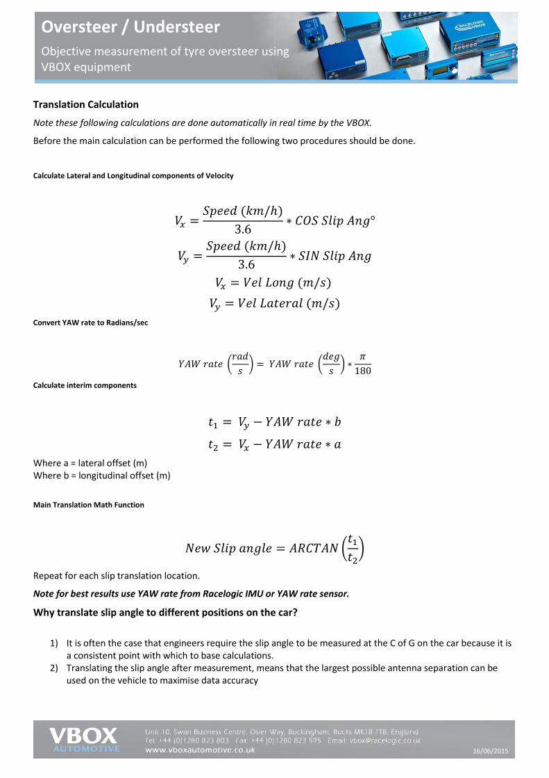
Translation Calculation
Note these following calculations are done automatically in real time by the VBOX.
Before the main calculation can be performed the following two procedures should be done.
Calculate Lateral and Longitudinal components of Velocity
𝑉𝑥 =𝑆𝑝𝑒𝑒𝑑 (𝑘𝑚/ℎ)
3.6∗ 𝐶𝑂𝑆 𝑆𝑙𝑖𝑝 𝐴𝑛𝑔°
𝑉𝑦 =𝑆𝑝𝑒𝑒𝑑 (𝑘𝑚/ℎ)
3.6∗ 𝑆𝐼𝑁 𝑆𝑙𝑖𝑝 𝐴𝑛𝑔
𝑉𝑥 = 𝑉𝑒𝑙 𝐿𝑜𝑛𝑔 (𝑚/𝑠)
𝑉𝑦 = 𝑉𝑒𝑙 𝐿𝑎𝑡𝑒𝑟𝑎𝑙 (𝑚/𝑠)
Convert YAW rate to Radians/sec
𝑌𝐴𝑊 𝑟𝑎𝑡𝑒 (𝑟𝑎𝑑
𝑠) = 𝑌𝐴𝑊 𝑟𝑎𝑡𝑒 (
𝑑𝑒𝑔
𝑠) ∗
𝜋
180
Calculate interim components
𝑡1 = 𝑉𝑦 − 𝑌𝐴𝑊 𝑟𝑎𝑡𝑒 ∗ 𝑏
𝑡2 = 𝑉𝑥 − 𝑌𝐴𝑊 𝑟𝑎𝑡𝑒 ∗ 𝑎
Where a = lateral offset (m) Where b = longitudinal offset (m)
Main Translation Math Function
𝑁𝑒𝑤 𝑆𝑙𝑖𝑝 𝑎𝑛𝑔𝑙𝑒 = 𝐴𝑅𝐶𝑇𝐴𝑁 (𝑡1
𝑡2)
Repeat for each slip translation location.
Note for best results use YAW rate from Racelogic IMU or YAW rate sensor.
Why translate slip angle to different positions on the car?
1) It is often the case that engineers require the slip angle to be measured at the C of G on the car because it is
a consistent point with which to base calculations. 2) Translating the slip angle after measurement, means that the largest possible antenna separation can be
used on the vehicle to maximise data accuracy
August 2011
Oct 2011
16/06/2015
Oversteer / Understeer Objective measurement of tyre oversteer using VBOX equipment
Body Slip Angle and Tyre Slip Angle
A VBOX measures body slip angle which is directly useful for general vehicle characterisation but to better understand the vehicle or tyre characteristics during dynamic manoeuvres then it is required to measure tyre slip angle.
When a vehicle understeers then the front tyres will exhibit a greater tyre slip angle than the rear tyres.
When a vehicle oversteers then the rear tyres will exhibit a greater tyre slip angle than the front tyres.
Measuring Tyre Slip Angle
Assuming grip is maintained, the body of vehicle will tend to follow the direction the steered tyres are pointing in but
momentum of the vehicle will mean that there will always be a level of tyre slip, however minimal this may be. The
tyre will deform slightly as it makes contact with the road and this deformation may also need to be considered.
This can be calculated by measuring the slip angle over the wheel and the actual wheel steering angle (which can
sometimes be obtained via CAN), then subtracting the slip angle from the wheel steering angle – the result is the tyre
slip angle. Note that wheel steering angle will need to be measured at each wheel, due to the effects of Ackerman
steering.
It is also possible fit sensors to individually measure the angle of each of the two front road wheels.
Measurements of true heading and course over ground are made directly via GPS - GPS does not suffer calculation errors associated with gyro drift
Antennas can be easily mounted on the roof of the car and using the Racelogic roof mount pole, maximum antenna separation can be achieved on virtually any vehicle roof.
Slip angle translation function means you can measure slip angle at any 5 points on the vehicle (such as over each wheel), even though the two antennas are in a set position on the roof
No lengthy calibration procedure is required after setup.
Changes in pitch do not affect slip angle.
August 2011
Oct 2011
16/06/2015
Oversteer / Understeer Objective measurement of tyre oversteer using VBOX equipment
Required and Useful Measurement Parameters
Parameter Source
Speed VBOX 3i Dual Antenna (VB3iSL)
Slip angle FR VBOX 3i Dual Antenna (VB3iSL)
Slip Angle FL VBOX 3i Dual Antenna (VB3iSL)
Slip Angle RR VBOX 3i Dual Antenna (VB3iSL)
Slip Angle RL VBOX 3i Dual Antenna (VB3iSL)
Steering angle Logged by the VBOX via External Sensor
Road Wheel angle FR Logged by the VBOX via External Sensor
Road Wheel angle FL Logged by the VBOX via External Sensor