INSTRUMENTS As a watch stander, you observe or monitor operating equipment and take the necessary steps to detect malfunctions and prevent damage to the equipment. The word monitor means to observe, record, or detect an operation or condition using instruments. Measurement, in a very real sense, is the language of engineers. The shipboard engineering plant has many instruments that indicate existing conditions within a piece of machinery or a system. By reading and interpreting the instruments, you can determine whether the machinery or the system is operating within the prescribed range.
Recorded instrument readings are used to make sure the plant is operating properly. They are also used to determine the operating efficiency of the plant. The instruments provide information for hourly, daily, and weekly entries for station operating records and reports. The data entered in the records and reports must be accurate since they are used to determine the condition of the plant over a period of time. Remember, for accurate data to be entered on the records and reports of an engineering plant, you must read the instruments carefully. In this chapter, we describe various types of indicating instruments that you, as a Fireman, come in contact with while working and standing watch on an engineering plant. Engineering measuring instruments are typically classified into the following groups:
• Pressure gauges
• Temperature detectors
• Temperature measuring devices
• Electrical indicating instruments
• Liquid-level indicators
• Revolution counters and indicators
• Salinity indicators
• Torque wrenches
LEARNING OBJECTIVES When you have completed this chapter, you will be able to do the following:
1. Recognize how to read and interpret gauges, indicators, and thermometers. 2. Identify the use of sensitive measuring tools. 3. Recognize the purpose of engine test equipment.
PRESSURE GAUGES The types of pressure gauges used in an engineering plant include Bourdon-tube gauges, bellows and diaphragm gauges, and manometers. Bourdon-tube gauges are generally used for measuring pressures above and below atmospheric pressure. Bellows and diaphragm gauges and manometers are generally used to measure pressures below 15 pounds-per-square-inch gauge (psig). They are also used for low vacuum pressure. Low vacuum pressure is slightly less than 14.7 pounds per
11-2
NOTE On dial pressure gauges, set the adjustable red hand (if installed) at or slightly above the maximum normal operating pressure, or at or slightly below the minimum normal operating pressure, (Refer to Naval Ships’ Technical Manual, Chapter 504, for specific instructions).
square inch absolute (psia). Often, pressure measuring instruments have scales calibrated in inches of water (inH2O) to allow greater accuracy.
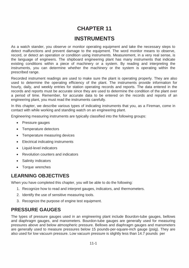
Bourdon-Tube Gauges The device usually used to indicate temperature changes by its response to volume changes or to pressure changes is called a Bourdon tube. A Bourdon tube is a C-shaped, curved or twisted tube that is open at one end and sealed at the other (Figure 11-1). The open end of the tube is fixed in position, and the scaled end is free to move. The tube is more or less elliptical in cross section; it does not form a true circle. The tube becomes more circular when there is an increase in the volume or the internal pressure of the contained fluid. The spring action of the tube metal opposes this action and tends to coil the tube. Since the open end of the Bourdon tube is rigidly fastened, the sealed end moves as the pressure of the contained fluid changes. There are many types of Bourdon-tube gauges used in the Navy. The most common ones are the simplex, duplex, vacuum, compound, and differential pressure gauges. They operate on the principle that pressure in a curved tube has a tendency to straighten out the tube. This curved tube is made of bronze for pressures under 200 pounds per square inch (psi) and of steel for pressures over 200 psi.
Simplex Bourdon-tube Gauge A simplex Bourdon tube installed in a gauge case is shown in Figure 11-2. Notice that the Bourdon tube is in the shape of the letter C and is welded or silver-brazed to the stationary base. The free end of the tube is connected to the indicating mechanism by a linkage assembly. The threaded socket, welded to the stationary base, is the pressure connection. When pressure enters the Bourdon tube, the tube tends to straighten out. The tube movement through linkage causes the pointer to move proportionally to the pressure applied to the tube. The simplex gauge is used for measuring the pressure of steam, air, water, oil, and similar fluids or gases.
Figure 11-1 — C-shaped Bourdon tube.
11-3
Figure 11-3 — Duplex Bourdon-tube pressure gauge.
Duplex Bourdon-tube Gauge The duplex Bourdon-tube gauge (Figure 11-3) has two tubes and two separate gear mechanisms within the same case. A pointer is connected to the gear mechanism of each tube. Each pointer operates independently. Duplex gauges are normally used to show pressure drops between the inlet and outlet sides of lube oil strainers. If the pressure reading for the inlet side of a strainer is much greater than the pressure reading for the outlet side, it may be assumed that the strainer is likely to be dirty and is restricting the flow of lube oil through the strainer.
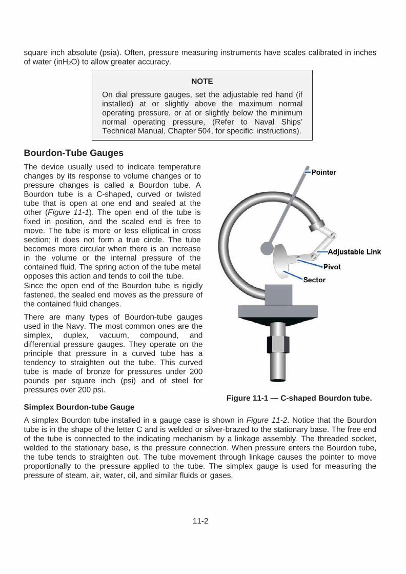
Bourdon-tube Vacuum Gauge, Compound Gauge, and Differential Pressure Gauge Bourdon-tube vacuum gauges are marked off in inches of mercury (inHg) (Figure 11-4). When a gauge is designed to measure both vacuum and pressure, it is called a compound gauge. Compound gauges are marked off both in inHg and in psig (Figure 11-5).
Differential pressure may also be measured with Bourdon-tube gauges. One kind of Bourdon-tube differential pressure gauge is shown in Figure 11-6. This gauge has two Bourdon tubes, but only one pointer. The Bourdon tubes are connected in such a way that they are the pressure difference, rather than either of the two actual pressures indicated by the pointer.
Bellows Gauge A bellows gauge contains an elastic element that is a convoluted unit that expands and contracts axially with changes in pressure. The pressure to be measured can be applied to the outside or inside of the bellows. However, in practice, most bellows measuring devices have the pressure applied to the outside of the bellows (Figure 11-7). Like Bourdon- tube elements, the elastic elements in bellows gauges are made of brass, phosphor bronze, stainless steel, beryllium-copper, or other metal that is suitable for the intended purpose of the gauge.
Most bellows gauges are spring-loaded; that is, a spring opposes the bellows, thus preventing full expansion of the bellows. Limiting the expansion of the bellows in this way protects the bellows and prolongs its life. In a spring-loaded bellows element, the deflection is the result of the force acting on the bellows and the opposing force of the spring. Although some bellows instruments can be designed for measuring pressures up to 800 psig, their primary application aboard ship is in the measurement of low pressures or small pressure differentials.
Many differential pressure gauges are of the bellows type. In some designs, one pressure is applied to the inside of the bellows, and the other pressure is applied to the outside. In other designs, a differential pressure reading is obtained by opposing two bellows in a single case. Bellows elements are used in various applications where the pressure-sensitive device must be powerful enough to operate not only the indicating pointer but also some type of recording device.
Figure 11-7 — Bellows gauge.
11-6
DIAPHRAGM GAUGES Diaphragm gauges are very sensitive and give reliable indication of small differences in pressure. Diaphragm gauges are generally used to measure air pressure in the space between the inner and outer boiler casings. The indicating mechanism of a diaphragm gauge is shown in Figure 11-8. This mechanism consists of a tough, pliable, neoprene rubber membrane connected to a metal spring that is attached by a simple linkage system to the gauge pointer. One side of the diaphragm is exposed to the pressure being measured, while the other side is exposed to the atmosphere. When pressure is applied to the diaphragm, it moves; and through a linkage system, moves the pointer to a higher reading on the dial. When the pressure is lowered, the diaphragm moves the pointer back toward the zero point.
Figure 11-8 — Diaphragm gauge.
MANOMETERS A manometer is perhaps the most accurate, least expensive, and simplest instrument for measuring low pressure or low-pressure differentials. In its simplest form, a manometer consists of either a straight or U- shaped glass tube of uniform diameter, filled with a liquid. The most common liquids used are water and oil. One end of the U-tube is open to the atmosphere, and the other end is connected to the pressure to be measured (Figure 11-9). The liquid reacts to the amount of pressure exerted on it and moves up or down within the tube. The amount of pressure is determined by matching the liquid level against a scale within the manometer.
TEMPERATURE MEASURING DEVICES Temperature is one of the basic engineering variables. Therefore, temperature measurement is essential to the proper operation of a shipboard engineering plant. As a watch stander, you will use both mechanical and electrical instruments to monitor Figure 11-9 — A. Standard U-tube
manometer. B. Single-tube manometer.
11-7
temperature levels. You will frequently be called on to measure the temperature of steam, water, fuel, lubricating oil, and other vital fluids. In many cases, you will enter the results of measurements in engineering logs and records.
Thermometers (Mechanical) Mechanical devices used to measure temperature are classified in various ways. In this section, we will discuss only the expansion thermometer types. Expansion thermometers operate on the principle that the expansion of solids, liquids, and gases has a known relationship to temperature change. The following types of expansion thermometers are discussed in this section:
• Liquid-in-glass thermometers
• Bimetallic expansion thermometers
• Filled-system thermometers
Liquid-in-Glass Thermometers Liquid-in-glass thermometers are the oldest, simplest, and most widely used devices for measuring temperature. A liquid-in-glass thermometer (Figure 11-10) has a bulb and a very fine-bore capillary tube. The tube contains alcohol or some other liquid that uniformly expands or contracts as the temperature rises or falls. The selection of liquid is based on the temperature range for which the thermometer is to be used. Almost all liquid-in-glass thermometers are sealed so atmospheric pressure does not affect the reading. The space above the liquid in this type of thermometer may be a vacuum, or this space maybe filled with an inert gas, such as nitrogen, argon, or carbon dioxide. The capillary bore may be round or elliptical. In either case, it is very small; therefore, a relatively small expansion or contraction of the liquid causes a relatively large change in the position of the liquid in the capillary tube. Although the capillary bore has a very small diameter, the walls of the capillary tube are quite thick. Most liquid-in- glass thermometers have an expansion chamber at the top of the bore to provide a margin of safety for the instrument if it should accidentally overheat. Liquid-in-glass thermometers may have graduations etched directly on the glass stem or placed on a separate strip of material located behind the stem. Many thermometers used in shipboard engineering plants have the graduations marked on a separate strip because this type is generally easier to read. You will find liquid-in-glass thermometers in use in the oil and water test lab for analytical tests on fuel, oil, and water.
Figure 11-10 — Liquid-in-glass thermometer.
11-8
expansion.
Bimetallic Expansion Thermometers Bimetallic expansion thermometers make use of different metals having different coefficients of linear expansion. The essential element in a bimetallic expansion thermometer is a bimetallic strip consisting of two layers of different metals fused together. When such a strip is subjected to temperature changes, one layer expands or contracts more than the other, thus tending to change the curvature of the strip.
The basic principle of a bimetallic expansion thermometer is shown in Figure 11-11. One end of a straight bimetallic strip is fixed in place. As the strip is heated, the other end tends to curve away from the side that has the greater coefficient of linear
When used in thermometers, the bimetallic strip is normally wound into a flat spiral (Figure 11-12), a single helix, or a multiple helix. The end of the strip that is not fixed in position is fastened to the end of a pointer that moves over a circular scale. Bimetallic thermometers are easily adapted for use as recording thermometers; a pen is attached to the pointer and positioned so that it marks on a revolving chart.
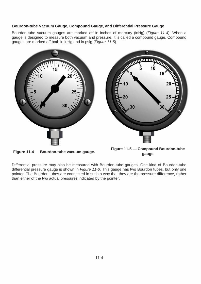
Filled-System Thermometers Generally, filled-system thermometers are used in locations where the indicating part of the instrument must be placed some distance away from the point where the temperature is to be measured. In a filled- system thermometer, temperature is converted into a mechanical motion caused by pressure or expansion. The components of a filled-system thermometer are comprised of the thermometer bulb, an expansion element, such as a Bourdon tube, diaphragm, capsule or bellows, and a capillary tube connecting the bulb and the expansion element. Some distant-reading thermometers have capillaries as long as 125 feet. There are two basic types of filled-system thermometers used in Navy applications. One type has a Bourdon tube that responds primarily to changes in the volume of the filling fluid. The other type has a Bourdon tube that responds primarily to changes in the pressure of the filling fluid. A distant-reading thermometer (Figure 11-13) consists of a hollow metal sensing bulb at one end of a small-bore capillary tube. The tube is connected to a Bourdon tube or other device that responds to volume changes or pressure changes. The system is partially or completely filled with a fluid that
Figure 11-11 — Effect of unequal expansion of a bimetallic strip.
expands when heated and contracts when cooled. The fluid may be a gas, an organic liquid, or a combination of liquid and vapor.
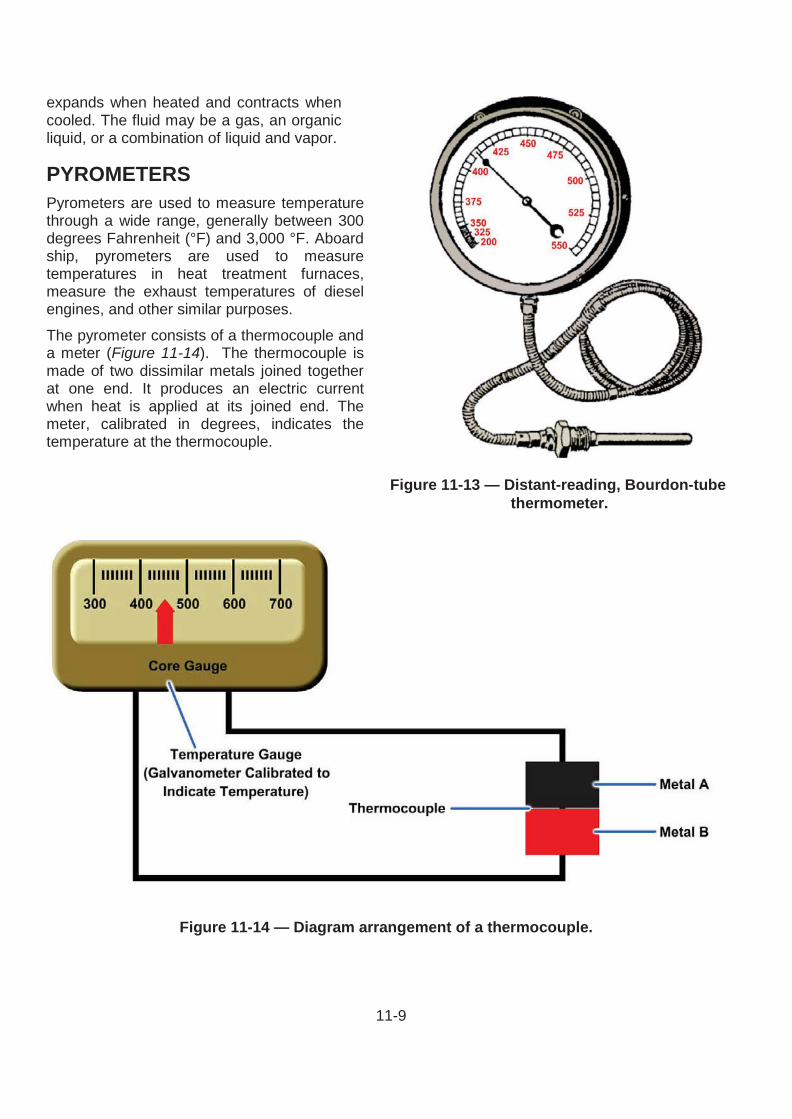
PYROMETERS Pyrometers are used to measure temperature through a wide range, generally between 300 degrees Fahrenheit (°F) and 3,000 °F. Aboard ship, pyrometers are used to measure temperatures in heat treatment furnaces, measure the exhaust temperatures of diesel engines, and other similar purposes.
The pyrometer consists of a thermocouple and a meter (Figure 11-14). The thermocouple is made of two dissimilar metals joined together at one end. It produces an electric current when heat is applied at its joined end. The meter, calibrated in degrees, indicates the temperature at the thermocouple.
Figure 11-14 — Diagram arrangement of a thermocouple.
11-10
ELECTRICAL TEMPERATURE MEASURING DEVICES On newer propulsion plants, temperature readings are monitored at remote locations. Expansion thermometers provide indications at the machinery locations or on gauge panels in the immediate thermometer area. To provide remote indications at a central location, electrical measuring devices along with signal conditioners are used. The devices discussed in this section include the resistance temperature detectors (RTDs), resistance temperature elements (RTEs), and thermocouples. These devices sense variable temperatures at a given point in the system and transmit the signals to a remotely located indicator.
Resistance Temperature Detectors (RTDs) The RTDs operate on the principle that electrical resistance changes in a predictable manner with changes in temperature. The elements of RTDs are made of nickel, copper, or platinum. Nickel and copper are used to measure temperatures below 600 °F. Platinum elements are used to measure temperatures above 600 °F. Two typical types of RTDs are shown in Figure 11-15.
Like bimetallic thermometers, RTDs are usually mounted in thermowells. Thermowells protect the sensors from physical damage by keeping them isolated from the medium being measured. This arrangement also allows the RTD to be changed without securing the system in which it is mounted. This makes the maintenance job easier. As temperature increases around an RTD, the corresponding resistance also increases proportionally. The temperature applied to an RTD, if known, gives a known resistance value. These resistance values can be found listed in tables in the manufacturers’ technical manuals. Normally, only a few resistance values are given. To test an RTD, it must be heated to a specific temperature. At this temperature, the resistance of the RTD should be at the resistance shown in the manufacturer’s table. The most common method of heating an RTD is to use a pan of hot water and a calibrated thermometer. Some newer ships and repair activities test RTDs using a thermobulb tester. This method is more accurate and easier to use. For specific instructions, refer to the manufacturers’ technical manuals supplied with the equipment. The most common fault found with an RTD is either a short circuit or an open circuit. These faults can be quickly diagnosed by using digital display readings or data log printouts. By observing the reading or the printout, the indication will be either zero or a very low value. A malfunction of this type means a short circuit exists in either the RTD or its associated wiring. A very high reading, such as 300 °F on a 0 to 300 °F RTD, could indicate an open circuit. These readings should be compared to local thermometers. This precaution ensures that no abnormal conditions exist within the equipment that the RTD serves.
Figure 11-15 — Two typical types of RTDs.
11-11
(Degree Fahrenheit) (Inches)
-60 to +500 6
If an RTD is faulty, it should be replaced. Internal repairs cannot be made at the shipboard level. Until the faulty RTD is replaced, the watch standers should be informed that the RTD is unreliable. The engine-room watch standers should take local readings periodically to make sure the equipment is operating normally.
Resistance Temperature Elements (RTEs) The RTEs are the most common type of temperature sensor found in gas turbine propulsion plants. The RTEs operate on the same principle as the RTDs. As the temperature of the sensor increases, the resistance of the RTE increases proportionally. All RTEs watch standers encounter have a platinum element. They have an electrical resistance of 100 ohms at a temperature of 32 °F. Four different temperature ranges of RTEs are commonly used, and the probe sizes vary. The four temperature ranges and their corresponding probe sizes are as follows:
TEMPERATURE RANGE RTE PROBE LENGTH
-20 to +150 6
0 to +1,000 2
Some RTEs are connected to remote mounted signal conditioning modules. These modules convert the ohmic value of the RTE to an output range of 4 to 20 milliampere (mA) direct current (dc). However, most RTEs read their value directly into the propulsion electronics as an ohmic value. The RTEs with temperature ranges from 0 to +400 °F and from -60 to +500 °F are commonly mounted in thermowells. Since an RTE can be changed without securing the equipment it serves, maintenance is simplified.
ELECTRICAL INDICATING INSTRUMENTS Electrical indicating instruments (meters) are used to display information that is measured by some type of electrical sensor. Although meters display units such as pressure or temperature, the meters on the control console are, in fact, dc voltmeters. The signal being sensed is conditioned by a signal conditioner. This is then converted to 0 to 10 volts dc, which is proportional to the parameters being sensed. Electrical values, such as power and current, are measured and displayed at ships’ service switchboards. Normally, shipboard repair is not done on switchboard meters. If it is suspected that the switchboard meters are out of calibration or broken, they should be sent to a repair facility. More information on the theory of operation of these meters can be found in the Navy Electricity and Electronics Training Series (NEETS), Module 3, Introduction to Circuit Protection, Control, and Measurement, NAVEDTRA 14175A.
Voltmeters Both dc and alternating current (ac) voltmeters determine voltage the same way. They both measure the current that the voltage is able to force through a high resistance. This resistance is connected in series with the indicating mechanism or element. Voltmeters installed in switchboards and control
0 to +400 2, 4, and 10
11-12
CAUTION
The secondary of a current transformer contains a dangerous voltage. Never work around or on current transformers without taking proper safety precautions.
consoles (Figure 11-16) all have a fixed resistance value. Portable voltmeters, used as test equipment, usually have a variable resistance. For both installed and portable voltmeters, resistances are calibrated to the different ranges that the meters will display. The normal range for the switchboard and electric plant meters is 0 to 600 volts.
Ammeters Ammeters are used to measure the amount of current passing through a conductor (Figure 11-17). Different types of ammeters are used to measure either ac or dc. Ammeters that are designed specifically to indicate ac will also measure dc, but with a lower degree of accuracy.
Ammeters must be connected in series with the circuit to be measured. For this reason, installed ammeters are constructed so that they do not handle the current that passes through the conductor being measured. Since ammeters cannot handle the high switchboard current, the switchboard ammeters operate through current transformers. This arrangement isolates the instruments from the line potential. In its secondary, the current transformer produces a definite fraction of the primary current. This arrangement makes it possible for large amounts of current to be measured with a small ammeter.
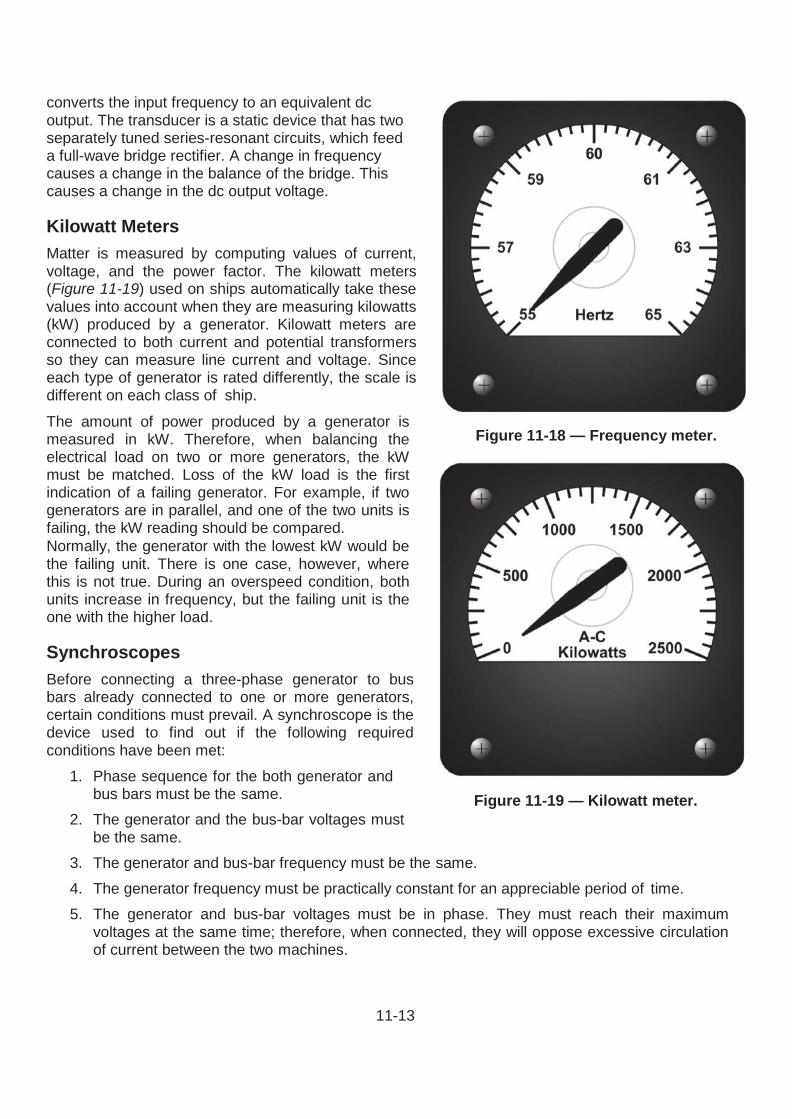
Frequency Meters Frequency meters (Figure 11-18) measure cycles per rate of ac. The range of frequency meters found on gas turbine ships is between 55 hertz (Hz) and 65 Hz. Frequency of the ac used on ships rarely varies below 57 Hz and seldom exceeds 62 Hz. A frequency meter may have a transducer that
Figure 11-16 — An ac voltmeter.
Figure 11-17 — An ac ammeter.
11-13
converts the input frequency to an equivalent dc output. The transducer is a static device that has two separately tuned series-resonant circuits, which feed a full-wave bridge rectifier. A change in frequency causes a change in the balance of the bridge. This causes a change in the dc output voltage.
Kilowatt Meters Matter is measured by computing values of current, voltage, and the power factor. The kilowatt meters (Figure 11-19) used on ships automatically take these values into account when they are measuring kilowatts (kW) produced by a generator. Kilowatt meters are connected to both current and potential transformers so they can measure line current and voltage. Since each type of generator is rated differently, the scale is different on each class of ship.
The amount of power produced by a generator is measured in kW. Therefore, when balancing the electrical load on two or more generators, the kW must be matched. Loss of the kW load is the first indication of a failing generator. For example, if two generators are in parallel, and one of the two units is failing, the kW reading should be compared. Normally, the generator with the lowest kW would be the failing unit. There is one case, however, where this is not true. During an overspeed condition, both units increase in frequency, but the failing unit is the one with the higher load.
Synchroscopes Before connecting a three-phase generator to bus bars already connected to one or more generators, certain conditions must prevail. A synchroscope is the device used to find out if the following required conditions have been met:
1. Phase sequence for the both generator and bus bars must be the same.
2. The generator and the bus-bar voltages must be the same.
3. The generator and bus-bar frequency must be the same. 4. The generator frequency must be practically constant for an appreciable period of time. 5. The generator and bus-bar voltages must be in phase. They must reach their maximum
voltages at the same time; therefore, when connected, they will oppose excessive circulation of current between the two machines.
Figure 11-18 — Frequency meter.
Figure 11-19 — Kilowatt meter.
11-14
A synchroscope is shown in Figure 11-20. It is basically a power factor meter connection to measure the phase relationship between the generator and bus-bar voltages. The moving element is free to rotate continuously. When the two frequencies are exactly the same, the moving element holds a fixed position. This shows the constant phase relationship between the generator and bus-bar voltages. When the frequency is slightly different, the phase relationship is always changing. When this happens, the moving element of the synchroscope rotates constantly. The speed of rotation is equal to the difference in frequency; the direction shows whether the generator is fast or slow. The generator is placed on line when the pointer slowly approaches a mark. This mark shows that the generator and bus-bar voltages are in phase.
Phase-Sequence Indicators A phase-sequence indicator (Figure 11-21) is used to determine the sequence in which the currents of a three-phase system reach their maximum values. Ships have phase-sequence indicators installed in switchboards that may be connected to shore power. These instruments indicate whether shore power is in the correct phase sequence with the ship before shipboard equipment is connected to shore power. Three-phase motors, when connected to incorrect phase-sequence power, rotate in the opposite direction. The phase-sequence indicator has three neon lamps that light when all three phases are energized. A meter connected to a network of resistors and condensers shows correct or incorrect sequence on a marked scale.
LIQUID-LEVEL INDICATORS A watch stander monitors systems and tanks for liquid levels. Sometimes, it is only required to know
Figure 11-21 — A phase-sequence indicator.
if a level exceeds or falls below a certain preset parameter. At other times, it is necessary to know the exact level. If only a predetermined limit is needed, a float switch can be used. When the set point is reached the float switch will make contact and sound an alarm. If a specific level is needed, a variable sensing device must be used. The sensor used to indicate a tank level is commonly called a tank level indicator (TLI). This sensor indicates the exact amount of liquid in a tank. In the following paragraphs, we will describe the operation of each of these sensors and their applications. The manufacturers’ technical manuals should be used for more information on the procedures used to adjust each type of device.
Figure 11-20 — Synchroscope.
11-15
Tank Level Indicators Many tank levels are monitored to provide the exact liquid level contained. For example, fuel tanks are monitored to make sure they do not overflow. They are also monitored to let the engineer officer know the amount of fuel aboard ship. The sensors used to monitor these levels are TLIs. Each of the level-monitored tanks contains a level transmitter. A typical transmitter section contains a voltage divider resistor network that extends the length of the section. Magnetic reed switches are tapped at 1-inch intervals along the resistor network. The reed switches are sequentially connected through series resistors to a common conductor. This network is enclosed in a stem that is mounted vertically in the tank. A float containing bar magnets rides up and down the stem as the liquid level changes. In many tanks, more than one transmitter section may have to be used to measure the full range. The physical arrangement of some tanks makes this necessary. When multiple sections are used, they are electrically connected as one continuous divider network. Two types of floats are used. In noncompensated tanks, the float is designed to float at the surface of the fuel or JP-5. For seawater-compensated tanks, the float is designed to stay at the seawater/fuel interface.
Contact Level Sensors Many times, the exact level of a tank does not have to be known until it reaches a preset level. When this type of indication is needed, a contact or float switch can be used. Two types of float level switches are used on gas turbine ships. One type of float level switch is the lever- activated switch, which is activated by a horizontal lever attached to a float. The float on this switch is located inside the tank. When the liquid level reaches a preset point, the lever activates the switch. The other type of level switch has a magnet- equipped float that slides on a vertical stem. The stem contains a hermetically sealed, reed switch. The float moves up and down the stem with the liquid level. It magnetically opens or closes the reed switch as the float passes over it. The construction of the magnetically- operated float switch is shown in Figure 11-22. Magnetic float switches may be constructed with more than one float on a stem. Magnetic float switches can be installed to detect multiple levels in the same tank; and this type of switch can activate a high- and low-level alarm.
REVOLUTION COUNTERS AND INDICATORS Measurements of rotational speed are necessary for the proper operation of pumps, forced-draft blowers, main engines, and other components of the engineering plants. Various types of instruments are used to measure equipment revolutions per minute (rpm) and count the number of revolutions a shaft makes.
Figure 11-22 — Magnetic float switch.
11-16
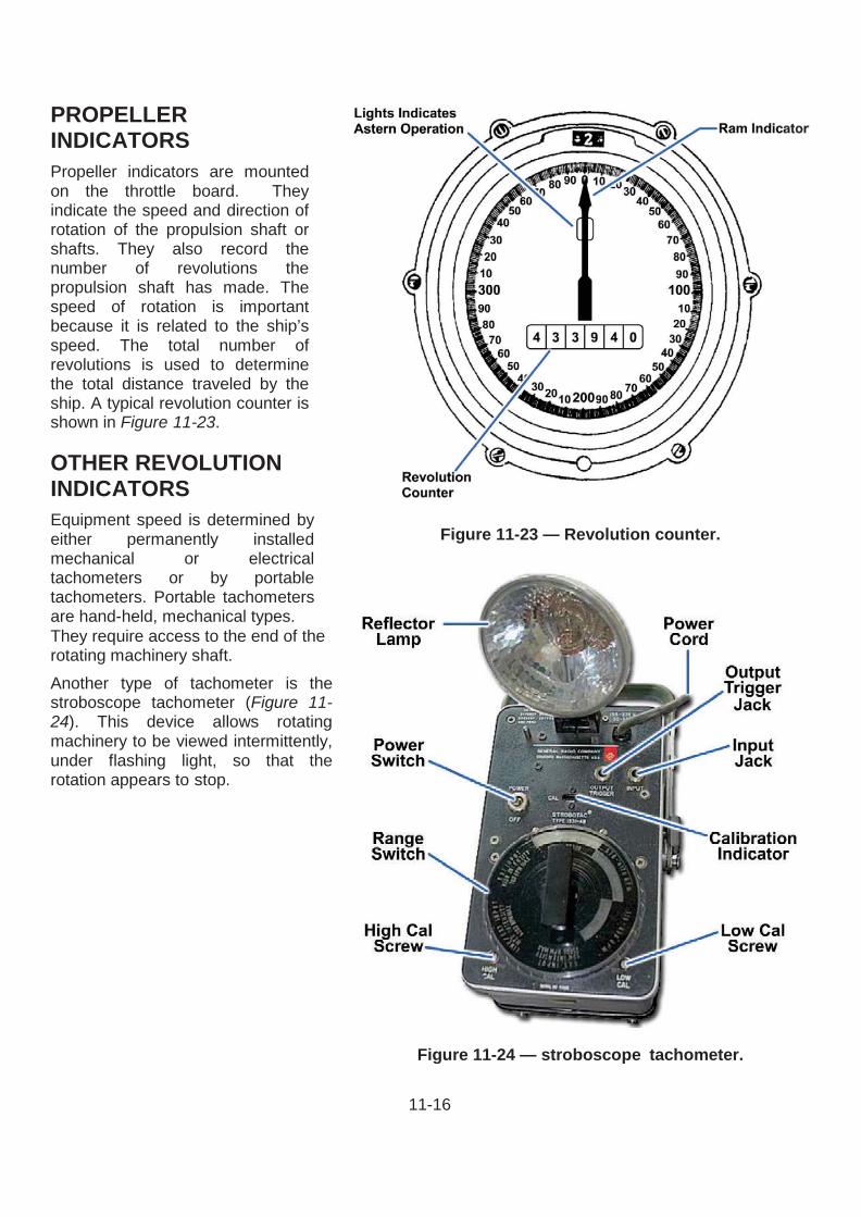
PROPELLER INDICATORS Propeller indicators are mounted on the throttle board. They indicate the speed and direction of rotation of the propulsion shaft or shafts. They also record the number of revolutions the propulsion shaft has made. The speed of rotation is important because it is related to the ship’s speed. The total number of revolutions is used to determine the total distance traveled by the ship. A typical revolution counter is shown in Figure 11-23.
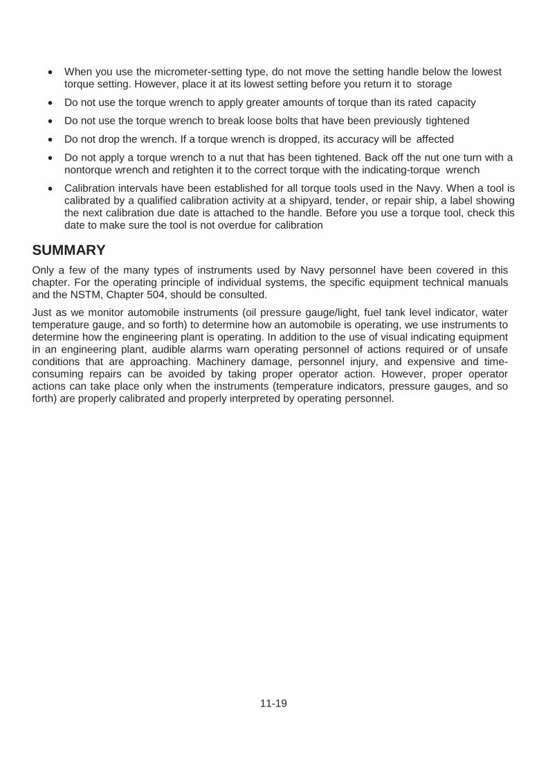
OTHER REVOLUTION INDICATORS Equipment speed is determined by either permanently installed mechanical or electrical tachometers or by portable tachometers. Portable tachometers are hand-held, mechanical types. They require access to the end of the rotating machinery shaft. Another type of tachometer is the stroboscope tachometer (Figure 11- 24). This device allows rotating machinery to be viewed intermittently, under flashing light, so that the rotation appears to stop.
Figure 11-23 — Revolution counter.
Figure 11-24 — stroboscope tachometer.
11-17
NOTE Other dissolved solids, in addition to ionized salt, may change the electrical resistance of water. To be safe, always assume that any resistance change is caused by ionized salt.
Because the light is intermittent, the eye receives a series of views rather than one continuous view. To measure the speed of a machine, rate of intermittent light should be found at which the machinery appears to be stopped. Then, either the speed of rotation should be read directly from the stroboscope’s indicator or the strobe’s flash rate converted to rpm.
SALINITY INDICATORS Electrical salinity indicating cells (Figure 11-25) are installed throughout distilling plants to maintain a constant check on the distilled water. An electrical salinity indicator consists of a number of salinity cells in various locations in the plant. For example, an electrical salinity indicator might consist of salinity cells placed in the evaporators, the condensate pump discharge, and the air-ejector condenser drain. These salinity cells are all connected to a salinity indicator panel. Since the electrical resistance of a solution varies according to the amount of ionized salts in the solution, it is possible to measure salinity by measuring the electrical resistance. The salinity indicator panel is equipped with a meter calibrated to read directly, either in equivalents per million (epm) or grains per gallon (gpg).
WARNING
If you use a stroboscopic tachometer, NEVER reach into the rotating machinery. Although the machinery appears to be stopped, it is still rotating.
Figure 11-25 — Salinity cell and valve assembly.
11-18
CAUTION
Be sure the torque wrench has been calibrated before you use it.
TORQUE WRENCHES At times, a specific force will need to be applied to a nut or bolt head. At these times, a torque wrench will be used. For example, equal force must be applied to all the head bolts of an engine. Otherwise, only one bolt may bear the brunt of the force of internal combustion, ultimately causing engine failure. A torque wrench will allow the specifically required force be applied. The three most commonly used torque wrenches are the deflecting beam, the dial-indicating, and the micrometer-setting types (Figure 11-26, views A through C). When using a deflecting-beam or dial- indicating torque wrench, the torque on a dial or scale mounted on the handle of the wrench can be visually read. The micrometer- setting torque wrench, however, indicates the torque value by sound. To use the micrometer-setting torque wrench, the grip should be unlocked and the handle adjusted to the desired setting on the scale; then, the grip relocked. Next, the required socket or adapter should be installed to the square drive of the handle. The wrench assembly should be placed on the nut or bolt and pulled in a clockwise direction, using a steady, smooth motion. (A fast or jerky motion results in an improperly torqued unit.) When the torque applied reaches the required torque value, a signal mechanism automatically issues an audible click; and the handle will release or break, moving freely for a short distance. The release and free travel are easily felt. This feature indicates that the torqueing process is complete.
A torque wrench that reads about mid-range for the amount of torque to be applied should be used. Manufacturers’ and technical manuals generally specify the amount of torque to be applied. To make sure the correct amount of torque is applied to the fasteners, the torque wrench according to the specific manufacturer’s instructions must be used. It is important to remember, the accuracy of torque measuring depends on how the threads are cut and the cleanliness of the threads. The threads must be inspected and cleaned. If the manufacturer specifies a thread lubricant, it should be used. When using deflecting-beam or dial-indicating wrenches, the torque should be held at the desired value until the reading is steady. Torque wrenches are delicate and expensive tools. When using them, these precautions should be followed:
Figure 11-26 — Torque wrenches.
11-19
• When you use the micrometer-setting type, do not move the setting handle below the lowest torque setting. However, place it at its lowest setting before you return it to storage
• Do not use the torque wrench to apply greater amounts of torque than its rated capacity
• Do not use the torque wrench to break loose bolts that have been previously tightened
• Do not drop the wrench. If a torque wrench is dropped, its accuracy will be affected
• Do not apply a torque wrench to a nut that has been tightened. Back off the nut one turn with a nontorque wrench and retighten it to the correct torque with the indicating-torque wrench
• Calibration intervals have been established for all torque tools used in the Navy. When a tool is calibrated by a qualified calibration activity at a shipyard, tender, or repair ship, a label showing the next calibration due date is attached to the handle. Before you use a torque tool, check this date to make sure the tool is not overdue for calibration
SUMMARY Only a few of the many types of instruments used by Navy personnel have been covered in this chapter. For the operating principle of individual systems, the specific equipment technical manuals and the NSTM, Chapter 504, should be consulted. Just as we monitor automobile instruments (oil pressure gauge/light, fuel tank level indicator, water temperature gauge, and so forth) to determine how an automobile is operating, we use instruments to determine how the engineering plant is operating. In addition to the use of visual indicating equipment in an engineering plant, audible alarms warn operating personnel of actions required or of unsafe conditions that are approaching. Machinery damage, personnel injury, and expensive and time- consuming repairs can be avoided by taking proper operator action. However, proper operator actions can take place only when the instruments (temperature indicators, pressure gauges, and so forth) are properly calibrated and properly interpreted by operating personnel.