CHAPTER 1-1 Cisco 3700 Series Routers Hardware Installation Guide OL-2180-08 1 Overview of Cisco 3700 Series Routers Cisco 3700 series routers are modular access routers with LAN and WAN connections that can be configured by means of interchangeable network modules and interface cards. This chapter describes the features and specifications of the routers and includes the following sections: • Hardware Features, page 1-1 • Modules, Interface Cards, and Memory, page 1-3 • Memory, page 1-4 • Interface Numbering, page 1-5 • Power Supply Options, page 1-9 • System Specifications, page 1-11 • Regulatory Compliance, page 1-12 Hardware Features Cisco 3700 series includes the Cisco 3725 and the Cisco 3745 routers, which provide the following features: • Cisco 3700 CompactFlash memory cards • Advanced integration module (AIM) slots • Support for double-wide network modules • Two sockets for synchronized DRAM (SDRAM) • User-configurable memory (shared memory or processor memory) • Two Fast Ethernet ports • High-speed console and auxiliary ports (up to 115.2 kbps) Cisco 3725 Cisco 3725 routers include the following additional features: • High-performance 240-MHz Reduced Instruction Set Computer (RISC) processor • Up to 256 MB SDRAM • Up to 128 MB CompactFlash memory
Transcript
Cisco 3700 SeriOL-2180-08
C H A P T E R 1
e
ctions:
ing
Overview of Cisco 3700 Series Routers
Cisco 3700 series routers are modular access routers with LAN and WAN connections that can bconfigured by means of interchangeable network modules and interface cards.
This chapter describes the features and specifications of the routers and includes the following se
• Hardware Features, page 1-1
• Modules, Interface Cards, and Memory, page 1-3
• Memory, page 1-4
• Interface Numbering, page 1-5
• Power Supply Options, page 1-9
• System Specifications, page 1-11
• Regulatory Compliance, page 1-12
Hardware FeaturesCisco 3700 series includes the Cisco 3725 and the Cisco 3745 routers, which provide the followfeatures:
• Cisco 3700 CompactFlash memory cards
• Advanced integration module (AIM) slots
• Support for double-wide network modules
• Two sockets for synchronized DRAM (SDRAM)
• User-configurable memory (shared memory or processor memory)
• Two Fast Ethernet ports
• High-speed console and auxiliary ports (up to 115.2 kbps)
Cisco 3725Cisco 3725 routers include the following additional features:
• High-performance 240-MHz Reduced Instruction Set Computer (RISC) processor
• Up to 256 MB SDRAM
• Up to 128 MB CompactFlash memory
1-1es Routers Hardware Installation Guide
Chapter 1 Overview of Cisco 3700 Series Routers Hardware Features
le
es
• Two slots for network modules, one of which can accommodate a double-wide network modu
• Three interface card slots
• Two Cisco 3700 CompactFlash slots (one external and one internal)
• Two AIM slots
• Installation in a 19- or 23-inch rack or on a desk
• Support for Cisco Redundant Power System
• 2-rack unit (RU) chassis height
Figure 1-1 shows the rear panel of the Cisco 3725 router.
Figure 1-1 Rear Panel of the Cisco 3725 Router
Cisco 3745Cisco 3745 routers include the following additional features:
• High-performance 350-MHz RISC processor
• Up to 256 MB SDRAM
• Up to 128 MB CompactFlash memory
• Four slots for network modules that can accommodate up to two double-wide network modul
• Three interface card slots
• Two Cisco 3700 CompactFlash memory card slots (one external and one internal)
Chapter 1 Overview of Cisco 3700 Series Routers Memory
ards
g by
3700
stem
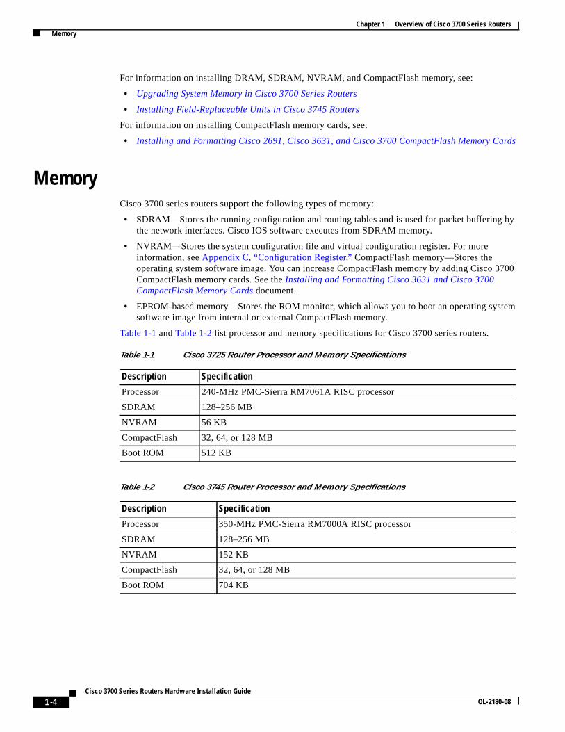
For information on installing DRAM, SDRAM, NVRAM, and CompactFlash memory, see:
• Upgrading System Memory in Cisco 3700 Series Routers
• Installing Field-Replaceable Units in Cisco 3745 Routers
For information on installing CompactFlash memory cards, see:
• Installing and Formatting Cisco 2691, Cisco 3631, and Cisco 3700 CompactFlash Memory C
MemoryCisco 3700 series routers support the following types of memory:
• SDRAM—Stores the running configuration and routing tables and is used for packet bufferinthe network interfaces. Cisco IOS software executes from SDRAM memory.
• NVRAM—Stores the system configuration file and virtual configuration register. For moreinformation, seeAppendix C, “Configuration Register.” CompactFlash memory—Stores theoperating system software image. You can increase CompactFlash memory by adding CiscoCompactFlash memory cards. See theInstalling and Formatting Cisco 3631 and Cisco 3700CompactFlash Memory Cards document.
• EPROM-based memory—Stores the ROM monitor, which allows you to boot an operating sysoftware image from internal or external CompactFlash memory.
Table 1-1 andTable 1-2 list processor and memory specifications for Cisco 3700 series routers.
Table 1-1 Cisco 3725 Router Processor and Memory Specifications
Chapter 1 Overview of Cisco 3700 Series Routers Interface Numbering
ers.
e
k
:
2/0
Interface NumberingThis section describes numbering conventions for interfaces on Cisco 3725 and Cisco 3745 rout
Cisco 3725 InterfacesEach individual interface (port) on a Cisco 3725 router is identified by number, as described in thfollowing sections.
WAN and LAN Interface Numbering
The Cisco 3725 router chassis contains the following WAN and LAN interface types:
• Two built-in Fast Ethernet LAN interfaces
• Three slots in which you can install WAN interface cards (WICs)
• One single-wide slot (slot 1) in which you can install one network module
• One double-wide slot (slot 2) in which you can install one single-wide or double-wide networmodule
The numbering format isinterface-type slot-number/interface-number. Two examples are:
• FastEthernet 0/0
• Serial 1/2
The slot numbers are as follows:
• 0 for all built-in interfaces
• 0 for all WIC interfaces
• 1 for interfaces in the single-wide network module slot
• 2 for interfaces in the double-wide network module slot
Interface (port) numbers begin at 0 for each interface type, and continue from right to left and (ifnecessary) from bottom to top.
Figure 1-3 shows an example of interface numbering on a Cisco 3725 router with these interfaces
• A WIC in each WIC slot (containing interfaces Serial 0/0 and Serial 0/1 in physical slot W0,interface Serial 0/2 in physical slot W1, and interface BRI 0/0 in physical slot W2)
• A 2-port T1 network module in slot 1 (containing the following ports: T1 1/0 and T1 1/1)
• A 36-port EtherSwitch network module in slot 2 (containing the following ports: Fast Ethernetthrough 2/35, and Gigabit Ethernet 2/0 and 2/1)
• Two built-in Ethernet 10/100-Mbps interfaces—Fast Ethernet 0/0 and Fast Ethernet 0/1
1-5Cisco 3700 Series Routers Hardware Installation Guide
OL-2180-08
Chapter 1 Overview of Cisco 3700 Series Routers Interface Numbering
icalch
llows:
s
in
ces slot
Figure 1-3 WAN and LAN Interface Numbering
The slot number for all WIC interfaces is always 0. (The W0 and W1 slot designations are for physslot identification only.) Interfaces in the WICs are numbered from right to left, starting with 0/0 for eainterface type, regardless of which physical slot the WICs are installed in. Some examples are as fo
• If slot W0 is empty and slot W1 contains a 1-port serial WIC, the serial interface in the WIC inumbered Serial 0/0.
• If slot W0 contains a 2-port serial WIC and slot W1 contains a 1-port serial WIC, the serialinterfaces in physical slot W0 are numbered Serial 0/0 and Serial 0/1, and the serial interfacephysical slot W1 is numbered Serial 0/2.
• If slot W0 contains a 2-port serial WIC and slot W1 contains a 1-port BRI WIC, the serial interfain physical slot W0 are numbered Serial 0/0 and Serial 0/1, and the BRI interface in physicalW1 is numbered BRI 0/0.
Voice Interface Numbering
Voice interfaces are numbered as follows:
chassis-slot/voice-module-slot/voice-interface
If a 4-channel voice network module is installed in chassis slot 1, the voice interfaces are:
Fast Ethernet 2/17 Gigabit Ethernet 2/0Fast Ethernet 2/0
Fast Ethernet 2/18
Serial 0/1Serial 0/0
TI 1/1 TI 1/0
Fast Ethernet 0/1Fast Ethernet 0/0
BRI 0/0
1
2
1-6Cisco 3700 Series Routers Hardware Installation Guide
OL-2180-08
Chapter 1 Overview of Cisco 3700 Series Routers Interface Numbering
e
:
m
orithples
e in
s inW1 is
s in1 is
Cisco 3745 InterfacesEach individual interface (port) on a Cisco 3745 router is identified by number as described in thfollowing sections.
WAN and LAN Interface Numbering
The Cisco 3745 router chassis contains the following WAN and LAN interface types:
• Two built-in FastEthernet LAN interfaces
• Three slots in which you can install WAN or voice interface cards
• Four network module slots
The numbering format isinterface-type slot-number/interface-number. Two examples are:
• FastEthernet 0/0
• Serial 1/2
The slot numbers are as follows:
• 0 for all built-in interfaces
• 0 for all WIC interfaces
• 1 for the lower-right network module slot
• 2 for the lower-left network module slot
• 3 for the upper-right network module slot
• 4 for the upper-left network module slot
If double-wide network modules are installed, the network module slots are numbered as follows
• 2 for the lower double-wide slot
• 4 for the upper double-wide slot
Interface (port) numbers begin at 0 for each interface type, and continue from right to left and frobottom to top.
Figure 1-4 shows the rear panel of the Cisco 3745 with:
• A WIC in each of the three WAN interface card slots
• A single-wide network module in each of the four network module slots
• Two AC power supplies
The slot number for all WIC interfaces is always 0. (The W0, W1, and W2 slot designations are fphysical slot identification only.) Interfaces in the WICs are numbered from right to left, starting w0/0 for each interface type, regardless of which physical slot the WICs are installed in. Some examare:
If physical slot W0 is empty and physical slot W1 contains a 1-port serial WIC, the serial interfacthe WIC is numbered Serial 0/0.
If slot W0 contains a 2-port serial WIC and slot W1 contains a 1-port serial WIC, the serial interfacephysical slot W0 are numbered Serial 0/0 and Serial 0/1, and the serial interface in physical slot numbered Serial 0/2.
If slot W0 contains a 2-port serial WIC and slot W1 contains a 1-port BRI WIC, the serial interfacephysical slot W0 are numbered Serial 0/0 and Serial 0/1, and the BRI interface in physical slot Wnumbered BRI 0/0.
1-7Cisco 3700 Series Routers Hardware Installation Guide
OL-2180-08
Chapter 1 Overview of Cisco 3700 Series Routers Interface Numbering
tion.
Figure 1-4 Cisco 3745 Rear Panel
Voice Interface Numbering
Voice interfaces are numbered differently from the WAN interfaces described in the previous secVoice interfaces are numbered as follows:
1-8Cisco 3700 Series Routers Hardware Installation Guide
OL-2180-08
Chapter 1 Overview of Cisco 3700 Series Routers Power Supply Options
eons.
erneto thets the
es boths do not
Power Supply OptionsTable 1-3 lists the power supply options supported by Cisco 3700 series routers. Depending on thconfiguration specified when you placed your order, your router may not support all of these opti
Internal –48 V Telephony Power ModulesCisco 3700 series routers provide inline power to IP phones connected to the router through Ethswitch network modules. This power is supplied by special –48 V modules that connect directly tchassis power supplies in Cisco 3725 and Cisco 3745 routers. A single –48 V power module meepower needs of up to 36 IP phones. A Cisco 3745 router with two –48 V power modules installedprovides redundant power for up to 36 IP phones.Figure 1-5 andFigure 1-6 show the –48 -V powermodules as they appear when installed in Cisco 3700 series routers.
Table 1-3 Power Supply Options for Cisco 3700 Series Routers
Power Supply Option Cisco 3725 Cisco 3745
AC input power Yes Yes
DC input power Yes Yes
–48-V telephony power module to provide inline power to IP phones Yes Yes
Dual hot-swappable power supplies No Yes1
1. Because of increased power consumption in high-temperature environments, a fully loaded Cisco 3745 router requirpower supplies when ambient temperature exceeds 104˚F (40˚C). Cisco 3745 routers operating under these conditionsupport the online replacement of power supplies.
Compatible with Cisco Redundant Power System Yes Yes
1-9Cisco 3700 Series Routers Hardware Installation Guide
OL-2180-08
Chapter 1 Overview of Cisco 3700 Series Routers Power Supply Options
Figure 1-5 Cisco 3725 Router with Optional –48 V Power Module Installed
Figure 1-6 Cisco 3745 Router with Optional –48 V Power Modules Installed
7208
6
-48V power module
ACpower module
7208
5
-48V power modules
1-10Cisco 3700 Series Routers Hardware Installation Guide
OL-2180-08
Chapter 1 Overview of Cisco 3700 Series Routers System Specifications
t
ce
ght
System SpecificationsTable 1-4 andTable 1-5 list Cisco 3700 series system specifications.
Table 1-4 Cisco 3725 Router System Specifications
Description Specification
Dimensions (H x W x D) 3.5 x 17.1 x 15.0 in. (8.9 x 43.4 x 38.1 cm), 2-RU chassis heigh
Weight 14 lb (6.4 kg)
Input voltage, AC power supplyFrequencyInput surge current (AC)
100 to 240 VAC, autoranging47–63 Hz50 A maximum, one cycle (–48-V power module included)
Input rating, DC power supply
Input surge current (DC)
24–36 VDC, 9 A, positive or negative, operational from 18–36 VDC
36–60 VDC, 4 A, positive or negative, operational from 36–72 VDC
50 A, < 10 ms
Power dissipation 135 W (maximum)
Heat Dissipation 135W Maximum 460.661 BTU/hour, 495W Maximum 1689.089BTU/hour
Console and auxiliary ports RJ-45 connector
Operating humidity 5–95%, noncondensing
Operating temperature 32–104°F (0–40°C)
Nonoperating temperature –40 to 162°F (–40 to 72°C)
Noise level 52 dBA (maximum)
Regulatory compliance FCC Part 15 Class A.
For additional compliance information, see theCisco 2600 Series,Cisco 3600 Series, and Cisco 3700 Series Regulatory Complianand Safety Informationdocument that accompanied the router.
Chapter 1 Overview of Cisco 3700 Series Routers Regulatory Compliance
s both
Regulatory ComplianceFor compliance information, see theCisco 2600 Series, Cisco 3600 Series, and Cisco 3700 SeriesRegulatory Compliance and Safety Informationdocument that accompanied the router.
Power dissipation 230 W (maximum)
Heat Dissipation 230W Maximum 784.829 BTU/hour, 590W Maximum 2013.257BTU/hour
Console and auxiliary ports RJ-45 connector
Operating humidity 5–95%, noncondensing
Operating temperature 32–104°F (0–40°C)1
Nonoperating temperature –40 to 162°F (–40 to 72°C)
Noise level 60 dBA (maximum)
Regulatory compliance FCC Part 15 Class A.
For additional compliance information, see theCisco 2600 Series,Cisco 3600 Series, and Cisco 3700 Series Regulatory Complianceand Safety Information document that accompanied the router.
1. Because of increased power consumption in high-temperature environments, a fully loaded Cisco 3745 router requirepower supplies when ambient temperature exceeds 104˚F (40˚C).
Table 1-5 Cisco 3745 Router System Specifications (continued)
Description Specification
1-12Cisco 3700 Series Routers Hardware Installation Guide