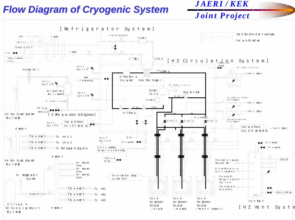
JAERI / KEKJoint ProjectFlow Diagram of Cryogenic SystemFlow Diagram of Cryogenic System
Vacuum Pump
Ortho-Para Ratio Measurement System
(Temp. Control System)
HeaderN2 Supply System(Outdoor)
Storage Tank
Evaporator
Flowmeter
Flowmeter
Flowmeter
To *N1
To *N2
To *N3
VentSystem
[H2 Pressure Control System]
Reservoir Tank(Accumulator)
PC control signal
Header
VentSystem
He Gus Supply System(Outdoor)
To Refrigerator System
Flowmeter
Flowmeter
Flowmeter
Header
H2 Gus Supply System(Outdoor)
From *He2
Air Actuated Valve
To Refrigerator System
Air Actuated ValveAir Actuated Valve
To *He1
To *He2
VentSystem
Vacuum Pump Unit (for pipe)
VentSystem
turbineLN2
Building Wall
Compressor
Vacuum pump unit
He
Vent
VentSystem
He(for catalyst)
turbine
[Refrigerator System]
From O-P Measurement System
From Vacuum Pump Unit
(Coupled)
Cold Moderator Module
(Decoupled)
Cold Moderator Module
(Poisoned decoupled)
Cold Moderator Module
Vacuum Pump
[H2 Vent System]
Vent Tank
(25m )
From H2 Pressure Control System
From Safety Valve, Rapture Disk
Vacuum Valve
PC control signal
Pre-moderator Cooling System (H2O)
From *N3
He
3 L/s
H2 Pump
50A
Heater
SurgeTank
Flowmeter
Bypass Line
0.9 L/s 0.6 L/s
0.9 L/s
0.6 L/s
~1.5MPa
(~19K)
Heater
Ortho-Para Converter Heat Exchanger
17.0 K[H2 Circulation System]
Vent System
From *N2
From *N2
Vacuum Pump Unit (for chamber)
Vent System
Vent System
Vacuum Pump Unit, He Supply System
Vacuum Pump Unit, He Supply System
Stack
Vacuum Boundary
Vent System
PC control signal
Inert Gas Brancket Boundary
He Refrigerator System
H2 Circulation System
Gus or LiquidSupply
H2 Pressure Control System
H2 Vent System
Vacuum Pump UnitVacuum Pump Unit
H2 Transfer TubesO-P MeasurementSystem
Cold Moderator Module
JAERI / KEKJoint ProjectFlow Diagram of Cryogenic SystemFlow Diagram of Cryogenic System
JAERI / KEKJoint Project
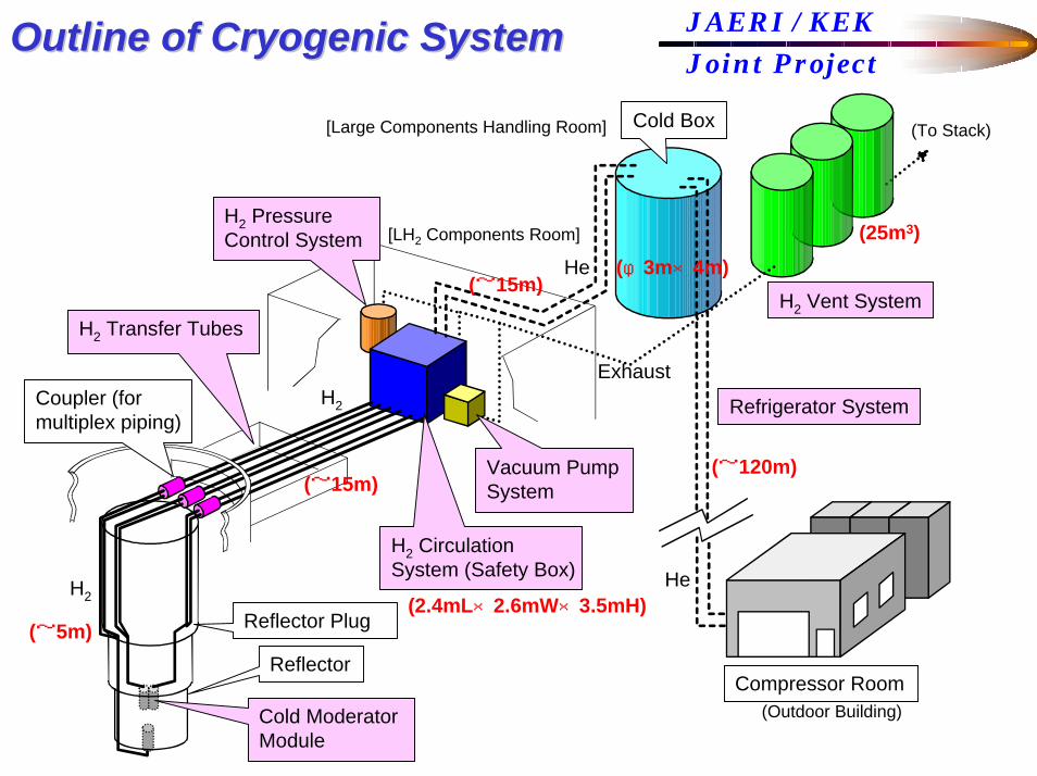
Outline of Cryogenic SystemOutline of Cryogenic System
Cold Moderator Module
Reflector
Reflector Plug
Coupler (for multiplex piping)
Compressor Room
Refrigerator System
H2 Vent System
Vacuum Pump System
H2 Circulation System (Safety Box)
H2 Pressure Control System
Cold Box
H2
H2
He
He
Exhaust
(Outdoor Building)
[Large Components Handling Room]
[LH2 Components Room]
(To Stack)
H2 Transfer Tubes
(~15m)
(~5m)
(~120m)
(25m3)(φ3m×4m)
(~15m)
(2.4mL×2.6mW×3.5mH)
JAERI / KEKJoint Project
Outline of Cryogenic SystemOutline of Cryogenic System
Cryogenic system consists of a H2 circulation system, a refrigerator system, H2 transfer tubes, three cold moderator modules, a H2 pressure control system, vacuum pump units and a H2 vent system.
Three cold moderator modules are fixed on the reflector plug which is vertically inserted in a helium vessel.
H2 circulation system covered by a safety box, H2 pressure control system, and vacuum pump units are installed in the H2 component room near the top of the reflector plug.H2 transfer tubes connect between the cold moderator modules and the H2 circulation system.
The cold box and the H2 vent system are installed in the large components handling room where is used to exchange the reflector plug. Other components of the refrigerator system are placed out of the MLF building.
[Large Components Handling Room]
H2 Circulation System (Safety Box)
[LH2 Components Room]Cold Box (Refrigerator)
1FL+12900
H2 Vent System
EPS
DSEPS
EPS
1FL+12900
1FL+10070
1FL+10100
1FL+10070
1FL+10100
1FL+10100
1FL+10100 1FL+10100遮蔽ハッチ
屋上
遮蔽ブロック遮蔽鉄置場
搬送
(50t)クレーン天井
デッキ(2)
上部
上部
第1実験ホール
第2実験ホール
PS
前室
冷却水機械室コールド
第2排気機械室
階段室(非管理)
第3給気機械室通路(非管理)
室
休憩室
制御室
コールド空調機械室
階段室(非管理)
大型機器取扱作業室
放出タンクエリア
給湯
PS非常用階段室(非管理)
階段室(管理)
第2実験ホール
コールド空調機械室
屋上
階段室
デッキ(2)搬送
階段室
コールド
遮蔽鉄置場
PS
冷却水機械室第1実験ホール
上部
上部
第2排気機械室
EPS DS
階段室
前室
第3給気機械室
大型機器取扱作業室
給湯 トイレ(男)
階段室(非管理)
PS
制御室
EPS
室
休憩室
通路(非管理)
EV(1)
EPS
階段室
休憩・展望室
(非管理)
(管理)
EV(2)
遮蔽ハッチ
遮蔽ハッチ
デッキ(1)デッキ(1)搬送搬送
天井クレーン(30t)1FL+
10070
1FL+10100
1FL+1010
0
1FL+1007
0
遮蔽ブロック1FL+10100
遮蔽ハッチ
天井クレーン
1FL+10100遮蔽ハッチ
(50t)
1FL+1290
0
遮蔽ハッチ
遮蔽ハッチ
1FL+10100
(30t)天井クレーン
(非管理)
非常用
(非管理)
クレーン点検台3FL+2800
歩廊
歩廊
50t台車(別途)
50t台車
点検歩廊1FL+17100点検歩廊1FL+17100
安全ガード付きタラップ
タラップ
点検歩廊1FL+16800点検歩廊
1FL+16800
タラップ
屋外階段
屋外階段
クレーン点検台3FL+2800タラップ
タラップ
床床:グレーチンググレーチング
トイレ(女)
遮蔽ハッチ
遮蔽ハッチ
1FL+12900
1FL+1290
0
排水ピット
排水ピット
(別途)
床開口
遮蔽ハッチ
SSSS
SSSS
EPSEPS
EPSEPS
コールドボックス
放出タンクエリア
コールドボックス
The safety box is located in the LH2components room.
The cold box and the vent system are located in the large components handling room.
JAERI / KEKJoint Project
Layout of Cryogenic SystemLayout of Cryogenic System
[H2 Components Room]
[Large Components Handling Room]
H2 Circulation System (Safety Box)
Cold Box (Refrigerator)
H2 Vent System
H2 Transfer TubeLevel of the safety box is higher than couplers of the multiplex piping.
Level of the cold box of refrigerator and the vent system are higher than the safety box.
Coupler (for multiplex piping)
JAERI / KEKJoint Project
FL12900
FL7450
FL
Layout of Cryogenic SystemLayout of Cryogenic System
SS
CS
N
ターゲット取扱室
反射体タ ゲット台車取扱室
SS
BL23
BL21
BL22
BL20BL19
BL18
取扱室
LN2 TankCompressor RoomH2, He
Cartridge Area
Secondary Cooling Water System
Cooling Tower
(1)(2)(3)
(5)(4)(6)
上部トップライト
階段室(非管理)
1FL±0
1FL±0
階段室(管理)
2次冷却配管ピット
2次冷却系ポンプ室
2次冷却系冷却塔
天井クレーン(20t)
第1ヘリウム圧縮機室
連絡路(1)
ユーティリティ連絡路(2)
EXP.J
EXP.J
C陽子ビームL
階段室(非管理)
M1
CミュオンLターゲット
C中性子ターゲットL
ユーティリティー配管ピット
気体廃棄物
T0チョッパー
2.8tクレーン
M2トンネル
配管ピット
1 20
ターゲット台車取扱室
(将来増築建家)
屋外階段
(将来増築建家)
連絡路(1)ユーティリティ
(Mアレナ)
ユーティリティ連絡路(2)
電源室
階段室
トンネル連絡通路
機械室
階段室(管理)
ホット冷却水
M1トンネル
第2機器搬出入口
設備室BT排水
第1機器搬出入口
階段室(非管理)
BT玄関
M2トンネル
第1実験ホール
ターゲット取扱室
CS
PS
屋外
(将来増築建家)
第1ヘリウム圧縮機室
T0チョッパー冷却系設備室
機器準備室
EPS DS
2次冷却系ポンプ室
EPS
第1機器調整室
PS
気体廃棄物処理設備室
反射体取扱室
通路1(管理)
機器搬出入エリア
階段室(非管理)
マニピュレータ操作室
PS
熱源機械室
第1給気機械室
EPS
玄関ホール
EV(1)
EPS
階段室
第3機器搬出入口
トレーラーヤード
階段室
ドライエリア
圧縮空気機械室
(非管理)
(管理)
配管ピット
液体窒素タンク
C陽子ビームL
EXP.J
EXP.J
EXP.J
M1
1FL±0
1FL±0
ターゲットCミュオンL
ユーティリティー配管ピット
ターゲットC中性子L
カードル置場
2次冷却配管ピット
天井クレーン(20t)
2次冷却系冷却塔
2.8tクレーン
SS
SS
トップライト上部
1
上部庇
20
階段
ジブクレーン稼動範囲(R=4500㎜)
(R=6500㎜)
床ピット
床ピット
(R=6500㎜)ジブクレーン稼動範囲
床ピット
床ピット
SS
SS
SS
SS
SS
SS
地下地下工作物
地下工作物
スロープ
スロープ
スロープ
スロープ
階段踏掛床版
階段踏掛床版
(下部踏掛床版)
スロープ
Pa
400φx1500H
1500□x1500H
1800x1000x1000H
8000x2000x1500H
床ピット2000φx1500H
床ピットBL13
BL14
BL15
BL17
BL16
BL23
BL21
BL22
BL20BL19
BL18
BL15
BL16
BL17
BL18
BL19
BL20
BL21
BL23
BL22
BL13
BL14
BL12
BL11
BL10
BL9
BL8 BL7
BL6
BL1
BL5
BL4
BL3
BL2
BL10
BL11
BL12
BL9
BL8
BL7
BL6
BL5
BL3
BL4
BL1
BL2
通路2(非管理)通路2(非管理)
前室前室
スロープ
スロープ
スロープ
スロープ
(非管理)
スロープ
スロープ
スロープ
スロープ
GL+200GL+200
GL±0GL±0
GL±0GL±0
スロープ(下部踏掛床版)スロープ
(下部踏掛床版)
EV(3)
EV(4)
第2ヘリウム圧縮機室圧縮機室
第2ヘリウム
SS
SS
屋外階段
屋外階段
(非管理)
(非管理)
ダムウェーター
(100kg)(100kg)
上部テルハレール
第2実験ホール第2実験ホール
ヘリウムタンクヘリウムタンク
調整室
地下工作物
10
5
4a
4
3
2
1
BTトンネルBTトンネル
EV(2)
床ハッチ
排水溝 排水溝
W=120W=120
S
グレーチング床
カートンボックス保管室
保管室
グレーチング床
置場
フェンス(別途)
(別途)
配管ピット配管ピット
W600x500HW600x500H
配管ピットW600x500H W600x500H
配管ピット
取扱室
床ハッチ置場 床ハッチ置場 床ハッチ
天井ハッチ
マニピュレータ操作室マニピュレータ操作室
PSPS
タラップ室タラップ室
ヘリウムボンベ置場
排水溝排水溝1000×1000100×50
100×50
上部テルハレール
上部テルハレール
R Q P O N M L K J I H G F E D C B A1 A A0
9
7a
6a
4.1
2.05
PS
EPS
DSEPS
EPS
SS
SS
床ピット
床ピット
床ピット
床ピット
EPS
(R=6500㎜)
(R=4500㎜)
M1トンネル
EXP.J
ユーティリティ
処理設備室
ヤードトレーラー
搬出入口第1機器
搬出入口第2機器
カードル置場
設備室BT排水
機械室ホット冷却水
(将来増築建家)
(将来増築建家)
(将来増築建家)
CS
PS
屋外階段
屋外階段
N液体窒素タンク
玄関BT
上部庇
トンネル連絡通路
機器準備室
機器搬出入エリア
第1機器
通路1(管理)
冷却系設備室
玄関ホール
第1給気機械室
階段室
熱源機械室
圧縮空気機械室
階段室
階段室(管理)
PS
ジブクレーン稼動範囲
ジブクレーン稼動範囲(R=6500㎜)
第1実験ホール
ターゲット取扱室
反射体
第3機器搬出入口
ターゲット台車取扱室
マニピュレータ操作室
Refrigerator System (except cold box)
The refrigerator components except the cold box are located out of the MLF building.
JAERI / KEKJoint Project
Layout of Cryogenic SystemLayout of Cryogenic System
He1
To Vacuum Pump
H2 Pump
To O-P Measurement System
PM(OUT)DM(OUT)
CM(OUT)
He(OUT)
He(IN)
PM(IN)DM(IN)
CM(IN)
To Vacuum Pump Unit
He2
Valve(25A)
Valve(50A)
()
1240
He Inert Branket
( )
VIEW from A
A
Valve(10A)
He(for ctalyst)
Vent
Vent
Vent
To Vacuum Pump Unit
H2 Pump
Valve(50A)
Valve(25A)
Valve(15A)
H2 PumpOrtho-Para Converter
Surge Tank
Heat Exchanger
Guide
The components of H2circulation system are installed in a safety box which is a vacuum vessel covered by inert blanket of He.
The safety box can be opened horizontally for maintenance and inspection on the Japanese high-pressure gas regulation including liquefied gas.
Type : Brayton cycleRefrigerator power : ~6kW (at 17K)
218WHeat inleake to hydrogen
1855WNuclear heating in hydrogen
1896WNuclear heating in moderator vessels including a poison
5521WTotal540WHeat input of the hydrogen pump1012WHeat inleake to transfer-lines
TC
H2
Heat Exchanger
He Cold- box
HeaterTurbine
Absorber
Compressor
Buffer tank
LN 2
Design Heat Loads
Flow Diagram of Refrigerator
JAERI / KEKJoint ProjectSummarySummary
Design of the cryogenic system consisting of the H2 circulation system and the refrigerator system makes in progress, referring the HFIR and the SNS facilities.
Overall layout plan of the cryogenic system was determined.
Based on this study, call for tender will be executed next April.