® SPECIFICATION SUBMITTAL Page Job Name: Job Number: Model Numbers: LED Dimming Driver EcoSystem® LED Driver Architectural Dimming 369341c 1 06.05.14 EcoSystem® LED Driver Overview The EcoSystem® LED Driver is a high-performance LED driver that provides smooth, continuous 1% dimming for virtually any LED fixture, whether it requires constant-current or constant-voltage. Features • Continuous, flicker-free dimming from 100% to 1% • EcoSystem® digital link control, compatible with EcoSystem® Energi Savr NodeTM modules and Quantum® systems • Can be used in conjunction with EcoSystem® compatible ballasts and devices • Protected from miswires of input power to EcoSystem® control inputs • CE and ENEC • Independent control gear with integral strain relief • SELV output • A rated lifetime of 50 000 hours @ t c = 75 °C • Constant current drivers with stabilized output current from 0,20 A to 1,05 A – Constant Current Reduction (CCR) dimming or Pulse Width Modulation (PWM) dimming. See Application Note #360 (P/N 048360) for details. • Constant voltage drivers with stabilized output voltage from 8 V to 40 V – Pulse Width Modulation (PWM) dimming • 100% performance tested at factory EcoSystem® LED Driver 89,7 mm W x 31,8 mm H x 154,7 mm L 1% Dimming LED Driver WARNING: Shock hazard. May result in serious injury or death. Disconnect power before servicing or installing. Warranty void if unit is opened. Coopersburg, PA 18036 USA EcoSystem® LED ta= 40 °C Pout: 25 W Max Vin: Iin: tc= freq: Vout: Iout: 220-240 V~ 0.140 A 75 °C 50 / 60 Hz 45 V- Max 1.05 A- 0 27557 00144 1 LDEA2E1CPA-JA105 λ= 0.95 TO EcoSytem® BUS +44 (0)20.7680.4481 E1 E2 LIVE 0,5 - 1,5 mm² 0,5 - 2,5 mm² Max. lead length 8 mm NEUTRAL 3,0 m (10 ft) t c DIGITAL BUS E1 E2 INPUT L SELV OUTPUT +V -V EcoSystem® LED Driver 0,5 - 2,5 mm² INPUT N 0,5 - 2,5 mm² LED load ONLY Copper wire only
Transcript
® SPECIF ICAT ION SUBMITTAL Page
Job Name:
Job Number:
Model Numbers:
LED Dimming Driver EcoSystem® LED Driver Architectural Dimming
369341c 1 06.05.14
EcoSystem® LED Driver Overview
The EcoSystem® LED Driver is a high-performance LED driver that provides smooth, continuous 1% dimming for virtually any LED fixture, whether it requires constant-current or constant-voltage.
Features
• Continuous, flicker-free dimming from 100% to 1%
• EcoSystem® digital link control, compatible with EcoSystem® Energi Savr NodeTM modules and Quantum® systems
• Can be used in conjunction with EcoSystem® compatible ballasts and devices
• Protected from miswires of input power to EcoSystem® control inputs
• CE and ENEC
• Independent control gear with integral strain relief
• SELV output
• A rated lifetime of 50 000 hours @ tc = 75 °C
• Constant current drivers with stabilized output current from 0,20 A to 1,05 A
– Constant Current Reduction (CCR) dimming or Pulse Width Modulation (PWM) dimming. See Application Note #360 (P/N 048360) for details.
• Constant voltage drivers with stabilized output voltage from 8 V to 40 V
– Pulse Width Modulation (PWM) dimming
• 100% performance tested at factory
EcoSystem® LED Driver
89,7 mm W x 31,8 mm H x 154,7 mm L
1% Dimming LED Driver
WARNING: Shock hazard. May result in serious injuryor death. Disconnect power before servicing or installing.
Warranty void if unit is opened.
Coopersburg, PA 18036 USA
EcoSystem® LED
ta= 40 °CPout: 25 W Max
Vin:Iin:
tc=freq:
Vout:Iout:
220-240 V~0.140 A
75 °C50 / 60 Hz
45 V- Max1.05 A-
0 27557 00144 1
LDEA2E1CPA-JA105
λ = 0.95
��
TOEcoSytem
®
BUS
+44 (0)20.7680.4481
E1
E2
LIVE
0,5 - 1,5 mm²
0,5 - 2,5 mm²
Max. lead length
8 mm
NEUTRAL
3,0 m (10 ft)
tc
DIG
ITAL B
US
E1
E2
INP
UT
L
SE
LVO
UTP
UT
+V-V
EcoSystem®
LEDDriver
0,5 - 2,5 mm²
INP
UT
N
0,5 - 2,5 mm²
LED load ONLY
Copper wire only
® SPECIF ICAT ION SUBMITTAL Page
Job Name:
Job Number:
Model Numbers:
LED Dimming Driver EcoSystem® LED Driver Architectural Dimming
369341c 2 06.05.14
Specifications
Performance
• Dimming Range: 100% to 1%
• Operating Voltage: 220–240 V~ at 50/60 Hz
• Patented thermal foldback protection
• LEDs turn on to any dimmed level without going to full brightness
• Non-volatile memory restores all driver settings after power failure
• Power Factor: λ >0,90 at full output for loads greater than 15 W
• Total Harmonic Distortion (THD): <20% for loads greater than 10 W
• Inrush Current: <2 A
• Inrush Current Limiting Circuitry: eliminates circuit breaker tripping, switch arcing and relay failure
• Open circuit protected
• Short circuit protected
• Lifetime: 50 000 hours @ tc = 75 °C
• Efficiency: > 80% at max power (25 W)
• Turn-on time: ≤ 1 second
Environmental
• Sound Rating: Inaudible in a 27 dB ambient
• Relative Humidity: maximum 90% non-condensing
• Minimum Operating Ambient Temperature: ta = 0 °C
• Maximum Calibration Point: tc = 75 °C
• Maximum Operating Ambient Temperature: ta = 40 °C
• Lutron® Quality Systems registered to ISO 9001.2008
Driver Wiring & Mounting
• Wiring Means: Daisy chain capable terminals for input
– Input Screw Terminals:
· 1 or 2 cables, 2 core 0,5 mm2 to 2,5 mm2
· Daisy Chain Maximum: 8 units
· Recommended Wire Types: H03VV-F, H03VVH2-F, H05VV-F, and H05VVH2-F
– EcoSystem® Terminals:
· 1 or 2 cables, 2 core 0,5 mm2 to 1,5 mm2 (Solid copper wire only)
· Recommended Wire Types: H03VV-U, H03VVH2-U, H05VV-U, and H05VVH2-U
– Output Screw Terminals:
· 1 cable, 2 core 0,5 mm2 to 2,5 mm2
· Recommended Wire Types: H03VV-F, H03VVH2-F, H05VV-F, and H05VVH2-F
Note: Ground termination not provided. Terminate ground in compliance with local electric codes
® SPECIF ICAT ION SUBMITTAL Page
Job Name:
Job Number:
Model Numbers:
LED Dimming Driver EcoSystem® LED Driver Architectural Dimming
369341c 3 06.05.14
How to Build a Model Number: EcoSystem® LED Driver
L DE A2E1C PA - _ _ _ _ _
Control Type:
DE = Digital EcoSystem® LED Driver
Constant Voltage
A = 8,0 V –12,0 V
B = 12,5 V – 20,0 V
C = 20,5 V – 24,0 V
D = 24,5 V – 40,0 V
1,05 A and 25 W maximum
Constant Current
G = 0,35 A –0,62 A 8 V – 20 V
H = 0,20 A –0,62 A 15 V – 40 V
I = 0,63 A –1,05 A 8 V – 20 V
J = 0,63 A –1,05 A 15 V – 40 V
40 V and 25 W maximum
Driver Output:
C = Constant current driver with pulse width modulation (PWM) dimming
A = Constant current driver with constant current reduction (CCR) dimming
V = Constant voltage driver with pulse width modulation (PWM) dimming
Current Level (for Constant Current):020 = 0,20 A; 021 = 0,21 A…105 = 1,05 A
Voltage Level (for Constant Voltage):080 = 8,0 V; 105 = 10,5 V…400 = 40,0 V
Example: LDEA2E1CPA-JA070
LED Load Output Range (see following pages for explanation and examples):
® SPECIF ICAT ION SUBMITTAL Page
Job Name:
Job Number:
Model Numbers:
LED Dimming Driver EcoSystem® LED Driver Architectural Dimming
369341c 4 06.05.14
“A” Output Range, Voltage Driver Models
0
0,2
0,4
0,6
0,8
11,05
0 5 108 12 8 1215 20 25 30 35 40
Output Current vs. Output Voltage
Output Voltage (V)
Out
put
Cur
rent
(A)
A
5 W Min.
Output Power vs. Output Voltage
Output Voltage (V)
Out
put
Po
wer
(W)
0
5
10
15
20
25
0 5 10 15 20 25 30 35 40
A
1,05 A Max.
Output Power (W)
Effi
cien
cy (%
)
Driver Efficiency vs. Output Power at 220 V~ – 240 V~(Max. light output)
60
65
70
75
80
85
90
5 6 7 8 9 10 11 12 13
10,0 V
12,0 V
8,0 V
Voltage Driver Operation Range:
Typical Performance Specifications:
0
0,2
0,4
0,6
0,8
11,05
0 5 108 12 8 1215 20 25 30 35 40
Output Current vs. Output Voltage
Output Voltage (V)
Out
put
Cur
rent
(A)
A
5 W Min.
Output Power vs. Output Voltage
Output Voltage (V)
Out
put
Po
wer
(W)
0
5
10
15
20
25
0 5 10 15 20 25 30 35 40
A
1,05 A Max.
Output Power (W)
Effi
cien
cy (%
)
Driver Efficiency vs. Output Power at 220 V~ – 240 V~(Max. light output)
60
65
70
75
80
85
90
5 6 7 8 9 10 11 12 13
10,0 V
12,0 V
8,0 V
Parameter 220 V~ 240 V~ Test Conditions
Input Current 80 mA 75 mA ta = 25 °C, 12,0 V 12,6 W load, Max. Light Output
Power Factor (λ) 0,87
THD 20%
Driver Efficiency 79%
Driver Type Output Dimming Method Output Voltage Output Current Output Power
Constant Voltage Driver Pulse Width Modulation (PWM) 8,0–12,0 V PWM 0,42–1,05 A 5–12,6 W
® SPECIF ICAT ION SUBMITTAL Page
Job Name:
Job Number:
Model Numbers:
LED Dimming Driver EcoSystem® LED Driver Architectural Dimming
369341c 5 06.05.14
“B” Output Range, Voltage Driver Models
0
0,2
0,4
0,6
0,8
1
0 5 10 12,5 15 20 25 30 35 40
Output Current vs. Output Voltage
Output Voltage (V)
Out
put
Cur
rent
(A)
Output Power vs. Output Voltage
Output Voltage (V)
Out
put
Po
wer
(W)
0
5
10
15
20
25
0 5 10 15 20 25 30 35 40
Output Power (W)
Effi
cien
cy (%
)
60
65
70
75
80
85
90
5 10 15 20 25
12,5
Driver Efficiency vs. Output Power at 220 V~ – 240 V~(Max. light output)
B
B
5 W Min.
1,05 A Max.
20,0 V
12,5 V
1,05
Voltage Driver Operation Range:
Typical Performance Specifications:
0
0,2
0,4
0,6
0,8
1
0 5 10 12,5 15 20 25 30 35 40
Output Current vs. Output Voltage
Output Voltage (V)
Out
put
Cur
rent
(A)
Output Power vs. Output Voltage
Output Voltage (V)
Out
put
Po
wer
(W)
0
5
10
15
20
25
0 5 10 15 20 25 30 35 40
Output Power (W)
Effi
cien
cy (%
)
60
65
70
75
80
85
90
5 10 15 20 25
12,5
Driver Efficiency vs. Output Power at 220 V~ – 240 V~(Max. light output)
B
B
5 W Min.
1,05 A Max.
20,0 V
12,5 V
1,05
Parameter 220 V~ 240 V~ Test Conditions
Input Current 120 mA 110 mA ta = 25 °C, 20,0 V 21,0 W load, Max. Light Output
Power Factor (λ) 0,94
THD 14%
Driver Efficiency 84%
Driver Type Output Dimming Method Output Voltage Output Current Output Power
Constant Voltage Driver Pulse Width Modulation (PWM) 12,5–20,0 V PWM 0,26–1,05 A 5–21 W
® SPECIF ICAT ION SUBMITTAL Page
Job Name:
Job Number:
Model Numbers:
LED Dimming Driver EcoSystem® LED Driver Architectural Dimming
369341c 6 06.05.14
“C” Output Range, Voltage Driver Models
0
0,2
0,4
0,6
0,8
1
0 5 10 15 20,5 24 30 35 40
Output Current vs. Output Voltage
Output Voltage (V)
Out
put
Cur
rent
(A)
Output Power vs. Output Voltage
Output Voltage (V)
Out
put
Po
wer
(W)
0
5
10
15
20
25
0 5 10 15 24 30 35 40
Output Power (W)
Effi
cien
cy (%
)
60
65
70
75
80
85
90
5 10 15 20 25
20,5
Driver Efficiency vs. Output Power at 220 V~ – 240 V~(Max. light output)
1,05 A Max.
20,5 V24,0 V
C
C
5 W Min.
1,05
Voltage Driver Operation Range:
Typical Performance Specifications:
0
0,2
0,4
0,6
0,8
1
0 5 10 15 20,5 24 30 35 40
Output Current vs. Output Voltage
Output Voltage (V)
Out
put
Cur
rent
(A)
Output Power vs. Output Voltage
Output Voltage (V)
Out
put
Po
wer
(W)
0
5
10
15
20
25
0 5 10 15 24 30 35 40
Output Power (W)
Effi
cien
cy (%
)
60
65
70
75
80
85
90
5 10 15 20 25
20,5
Driver Efficiency vs. Output Power at 220 V~ – 240 V~(Max. light output)
1,05 A Max.
20,5 V24,0 V
C
C
5 W Min.
1,05
Parameter 220 V~ 240 V~ Test Conditions
Input Current 135 mA 130 mA ta = 25 °C, 24,0 V 25,0 W load, Max. Light Output
Power Factor (λ) 0,96
THD 12%
Driver Efficiency 85%
Driver Type Output Dimming Method Output Voltage Output Current Output Power
Constant Voltage Driver Pulse Width Modulation (PWM) 20,5–24,0 V PWM 0,21–1,05 A 5–25 W
® SPECIF ICAT ION SUBMITTAL Page
Job Name:
Job Number:
Model Numbers:
LED Dimming Driver EcoSystem® LED Driver Architectural Dimming
369341c 7 06.05.14
“D” Output Range, Voltage Driver Models
0
0,2
0,4
0,6
0,8
1
0 5 10 15 20 24,5 30 35 40
Output Current vs. Output Voltage
Output Voltage (V)
Out
put
Cur
rent
(A)
Output Power vs. Output Voltage
Output Voltage (V)
Out
put
Po
wer
(W)
0
5
10
15
20
25
0 5 10 15 24,5 30 35 40
Output Power (W)
Effi
cien
cy (%
)
60
65
70
75
80
85
90
5 10 15 20 25
20
Driver Efficiency vs. Output Power at 220 V~ – 240 V~(Max. light output)
40,0 V
24,5 V
5 W Min.
25 W Max.
D
D
Voltage Driver Operation Range:
Typical Performance Specifications:
0
0,2
0,4
0,6
0,8
1
0 5 10 15 20 24,5 30 35 40
Output Current vs. Output Voltage
Output Voltage (V)
Out
put
Cur
rent
(A)
Output Power vs. Output Voltage
Output Voltage (V)
Out
put
Po
wer
(W)
0
5
10
15
20
25
0 5 10 15 24,5 30 35 40
Output Power (W)
Effi
cien
cy (%
)
60
65
70
75
80
85
90
5 10 15 20 25
20
Driver Efficiency vs. Output Power at 220 V~ – 240 V~(Max. light output)
40,0 V
24,5 V
5 W Min.
25 W Max.
D
D
Parameter 220 V~ 240 V~ Test Conditions
Input Current 140 mA 130 mA ta = 25 °C, 40,0 V 25,0 W load, Max. Light Output
Power Factor (λ) 0,96
THD 10%
Driver Efficiency 85%
Driver Type Output Dimming Method Output Voltage Output Current Output Power
Constant Voltage Driver Pulse Width Modulation (PWM) 24,5–40,0 V PWM 0,13–1,02 A 5–25 W
® SPECIF ICAT ION SUBMITTAL Page
Job Name:
Job Number:
Model Numbers:
LED Dimming Driver EcoSystem® LED Driver Architectural Dimming
369341c 8 06.05.14
“G” Output Range, Current Driver Models
Output Voltage vs. Output Current
Output Current (A)
Out
put
Vo
ltag
e (V
)
Output Power vs. Output Current
Output Current (A)
Out
put
Po
wer
(W)
0
5
10
15
20
25
30
35
40
0 0,2 0,35 0,62 0,8 10
5
10
15
20
25
0 0,2 0,35 0,62 0,8 1
Output Power (W)
Effi
cien
cy (%
)
60
65
70
75
80
85
90
5 6 7 8 9 10 11 12 13
Driver Efficiency vs. Output Power at 220 V~ – 240 V~(Max. light output)
0,50 A
0,35 A
0,62 A
5 W Min.
G
G20 V Max.
Current Driver Operation Range:
Typical Performance Specifications:
Output Voltage vs. Output Current
Output Current (A)
Out
put
Vo
ltag
e (V
)
Output Power vs. Output Current
Output Current (A)
Out
put
Po
wer
(W)
0
5
10
15
20
25
30
35
40
0 0,2 0,35 0,62 0,8 10
5
10
15
20
25
0 0,2 0,35 0,62 0,8 1
Output Power (W)
Effi
cien
cy (%
)
60
65
70
75
80
85
90
5 6 7 8 9 10 11 12 13
Driver Efficiency vs. Output Power at 220 V~ – 240 V~(Max. light output)
0,50 A
0,35 A
0,62 A
5 W Min.
G
G20 V Max.
Parameter 220 V~ 240 V~ Test Conditions
Input Current 80 mA 75 mA ta = 25 °C, 0,62 A 12,4 W load, Max. Light Output
Power Factor (λ) 0,89
THD 14%
Driver Efficiency 78%
Driver Type Output Dimming Method Output Voltage Output Current Output Power
Constant Current DriverPulse Width Modulation (PWM) 8,0–20,0 V PWM
0,35–0,62 A 5–12,4 WConstant Current Reduction (CCR) 8,0–20,0 V-
® SPECIF ICAT ION SUBMITTAL Page
Job Name:
Job Number:
Model Numbers:
LED Dimming Driver EcoSystem® LED Driver Architectural Dimming
369341c 9 06.05.14
“H” Output Range, Current Driver Models
Output Voltage vs. Output Current
Output Current (A)
Out
put
Vo
ltag
e (V
)
Output Power vs. Output Current
Output Current (A)
Out
put
Po
wer
(W)
0
5
10
15
20
25
30
35
40
0 0,2 0,4 0,62 0,8 10
5
10
15
20
25
0 0,2 0,4 0,62 0,8 1
Output Power (W)
Effi
cien
cy (%
)
60
65
70
75
80
85
90
5 10 15 20 25
Driver Efficiency vs. Output Power at 220 V~ – 240 V~(Max. light output)
0,50 A
0,35 A
0,20 A 0,62 A
5 W Min.
H
H40 V Max.
15 V Min.
Current Driver Operation Range:
Typical Performance Specifications:
Output Voltage vs. Output Current
Output Current (A)
Out
put
Vo
ltag
e (V
)
Output Power vs. Output Current
Output Current (A)
Out
put
Po
wer
(W)
0
5
10
15
20
25
30
35
40
0 0,2 0,4 0,62 0,8 10
5
10
15
20
25
0 0,2 0,4 0,62 0,8 1
Output Power (W)
Effi
cien
cy (%
)
60
65
70
75
80
85
90
5 10 15 20 25
Driver Efficiency vs. Output Power at 220 V~ – 240 V~(Max. light output)
0,50 A
0,35 A
0,20 A 0,62 A
5 W Min.
H
H40 V Max.
15 V Min.
Parameter 220 V~ 240 V~ Test Conditions
Input Current 140 mA 130 mA ta = 25 °C, 0,62 A 25,0 W load, Max. Light Output
Power Factor (λ) 0,96
THD 10%
Driver Efficiency 83%
Driver Type Output Dimming Method Output Voltage Output Current Output Power
Constant Current DriverPulse Width Modulation (PWM) 15,0–40,0 V PWM
0,20–0,62 A 5–24,8 WConstant Current Reduction (CCR) 15,0–40,0 V-
® SPECIF ICAT ION SUBMITTAL Page
Job Name:
Job Number:
Model Numbers:
LED Dimming Driver EcoSystem® LED Driver Architectural Dimming
369341c 10 06.05.14
“I” Output Range, Current Driver Models
Output Voltage vs. Output Current
Output Current (A)
Out
put
Vo
ltag
e (V
)
Output Power vs. Output Current
Output Current (A)
Out
put
Po
wer
(W)
0
5
10
15
20
25
30
35
40
0 0,2 0,4 0,63 0,8 1,050
5
10
15
20
25
0 0,2 0,4 0,63 0,8 1,05
Output Power (W)
Effi
cien
cy (%
)
60
65
70
75
80
85
90
5 10 15 20 25
8
Driver Efficiency vs. Output Power at 220 V~ – 240 V~(Max. light output)
0,63 A
1,05 A0,70 A
I
I
20 V Max.
8 V Min.
Current Driver Operation Range:
Typical Performance Specifications:
Output Voltage vs. Output Current
Output Current (A)
Out
put
Vo
ltag
e (V
)
Output Power vs. Output Current
Output Current (A)
Out
put
Po
wer
(W)
0
5
10
15
20
25
30
35
40
0 0,2 0,4 0,63 0,8 1,050
5
10
15
20
25
0 0,2 0,4 0,63 0,8 1,05
Output Power (W)
Effi
cien
cy (%
)
60
65
70
75
80
85
90
5 10 15 20 25
8
Driver Efficiency vs. Output Power at 220 V~ – 240 V~(Max. light output)
0,63 A
1,05 A0,70 A
I
I
20 V Max.
8 V Min.
Parameter 220 V~ 240 V~ Test Conditions
Input Current 125 mA 115 mA ta = 25 °C, 1,05 A 21,0 W load, Max. Light Output
Power Factor (λ) 0,95
THD 14%
Driver Efficiency 81%
Driver Type Output Dimming Method Output Voltage Output Current Output Power
Constant Current DriverPulse Width Modulation (PWM) 8,0–20,0 V PWM
0,63–1,05 A 5–21 WConstant Current Reduction (CCR) 8,0–20,0 V-
® SPECIF ICAT ION SUBMITTAL Page
Job Name:
Job Number:
Model Numbers:
LED Dimming Driver EcoSystem® LED Driver Architectural Dimming
369341c 11 06.05.14
“J” Output Range, Current Driver Models
Output Voltage vs. Output Current
Output Current (A)
Out
put
Vo
ltag
e (V
)
Output Power vs. Output Current
Output Current (A)
Out
put
Po
wer
(W)
0
5
10
15
20
25
30
35
40
0 0,2 0,4 0,63 0,8 1,050
5
10
15
20
25
0 0,2 0,4 0,63 0,8 1,05
Output Power (W)
Effi
cien
cy (%
)
60
65
70
75
80
85
90
5 10 15 20 25
Driver Efficiency vs. Output Power at 220 V~ – 240 V~(Max. light output)
0,63 A
1,05 A
0,70 A
J
J
15 V Min.
25 W Max.
Current Driver Operation Range:
Typical Performance Specifications:
Output Voltage vs. Output Current
Output Current (A)
Out
put
Vo
ltag
e (V
)
Output Power vs. Output Current
Output Current (A)
Out
put
Po
wer
(W)
0
5
10
15
20
25
30
35
40
0 0,2 0,4 0,63 0,8 1,050
5
10
15
20
25
0 0,2 0,4 0,63 0,8 1,05
Output Power (W)
Effi
cien
cy (%
)
60
65
70
75
80
85
90
5 10 15 20 25
Driver Efficiency vs. Output Power at 220 V~ – 240 V~(Max. light output)
0,63 A
1,05 A
0,70 A
J
J
15 V Min.
25 W Max.
Parameter 220 V~ 240 V~ Test Conditions
Input Current 145 mA 135 mA ta = 25 °C, 1,05 A 25,0 W load, Max. Light Output
Power Factor (λ) 0,96
THD 12%
Driver Efficiency 82%
Driver Type Output Dimming Method Output Voltage Output Current Output Power
Constant Current DriverPulse Width Modulation (PWM) 15,0–39,7 V PWM
0,63–1,05 A 9,5–25 WConstant Current Reduction (CCR) 15,0–39,7 V-
® SPECIF ICAT ION SUBMITTAL Page
Job Name:
Job Number:
Model Numbers:
LED Dimming Driver EcoSystem® LED Driver Architectural Dimming
369341c 12 06.05.14
Case Dimensions
A 31,8 mmB 89,7 mmC 154,7 mmD 90 mmE 143,5 mmF 4,6 mmG 34,3 mmH 48,6 mm
A
CB
Mounting Centers
E
G
H
F
D
® SPECIF ICAT ION SUBMITTAL Page
Job Name:
Job Number:
Model Numbers:
LED Dimming Driver EcoSystem® LED Driver Architectural Dimming
369341c 13 06.05.14
EcoSystem® LED Driver Wiring Diagrams
EcoSystem® Digital Link Overview
• The EcoSystem® Digital Link wiring (E1 and E2) connects the drivers together to form a lighting control system
• Each EcoSystem® Digital Link supports up to 64 EcoSystem® devices, 64 occupant sensors, 16 daylight sensors, and 64 wallstations or IR receivers
• E1 and E2 (EcoSystem® digital link wires) are polarity insensitive and can be wired in any topology
• An EcoSystem® Energi Savr NodeTM module or Quantum® system provides power for the EcoSystem® Digital Link and supports system programming
• All EcoSystem® Digital Link programming is completed by using the Energi Savr App for Apple iPad, iPod Touch or iPhone mobile digital devices, EcoSystem® Programmer, or Quantum® system
EcoSystem® Digital Link Wiring
• Driver EcoSystem® Digital Link terminals only accept one 0,50 mm2 to 1,5 mm2 (20 AWG to 16 AWG) solid copper wire per terminal
• Make sure that the mains breaker to the Driver and EcoSystem® Digital Link Supply is OFF when wiring
• Connect the two conductors to the two Driver terminals E1 and E2 as shown
• Using two different colors for E1 and E2 will reduce confusion when wiring several drivers together
• Consult applicable electrical codes for proper wiring practices
Notes
• The EcoSystem® Digital Link Supply does not have to be located at the end of the Digital Link
• EcoSystem® Digital Link length is limited by the wire gauge used for E1 and E2 as follows:
Wire GaugeDigital Link Length (max)
0,50 mm2 (20 AWG) 103 m
0,75 mm2 (18 AWG) 155 m
1,0 mm2 207 m
1,5 mm2 (16 AWG) 310 m
2,5 mm2 (14 AWG) 517 m
4,0 mm2 (12 AWG) 828 m
DIGITAL BUSUNIT 1 UNIT 2
E1 E2DIGITAL BUSE1 E2
EcoSystem® Daisy-Chain Wiring
To EcoSystem® Digital Link compatible devices (up to 64 total devices)
Apple, iPad, iPod Touch, and iPhone are trademarks of Apple Inc., registered in the U.S. and other countries.
® SPECIF ICAT ION SUBMITTAL Page
Job Name:
Job Number:
Model Numbers:
LED Dimming Driver EcoSystem® LED Driver Architectural Dimming
Solid 18 or 16 AWG wire for power and bus terminals 18 AWG wire only for lamps.
5/16 in (8 mm)
1-800-523-9466
Copper wire only
Consult lamp manufacturer for lamp seasoning requirements prior to dimming.
Warranty void if unit is opened.
WARNING: Shock hazard. May result in serious injury or death. Disconnect power before servicing or installing.
Calibration point temperature not to exceed 65 °C.Maximum case temperature 75 °C.
Ecosystem® H
TO LI
NEVO
LTAG
ESO
URCE
Pantone362
500-13362 Rev. ALabel Size: 6.87” x 2.125” Corner Radius: 0.0625”
Colors:Pantone186
Pantone1585
Pantone116
Pantone3005
Pantone2583
PantoneBlack
EcoSystem® LED Driver
-V
+V
*
*
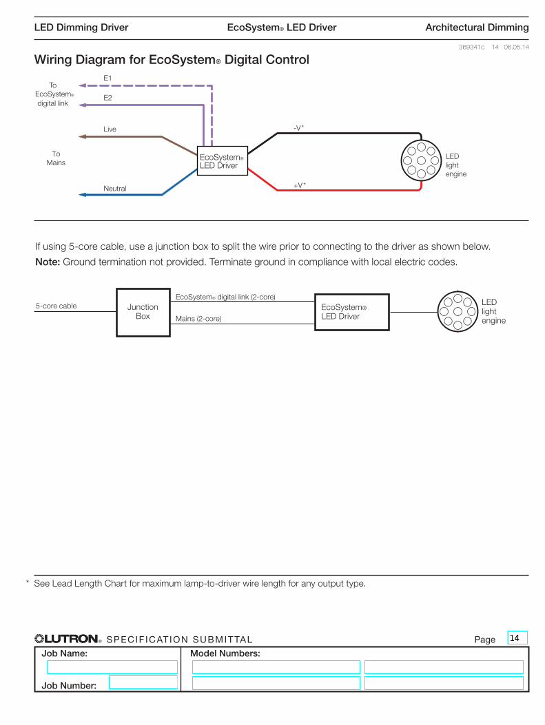
Wiring Diagram for EcoSystem® Digital Control
If using 5-core cable, use a junction box to split the wire prior to connecting to the driver as shown below.
Note: Ground termination not provided. Terminate ground in compliance with local electric codes.
Junction Box
EcoSystem® LED Driver
LED light engine
EcoSystem® digital link (2-core)
Mains (2-core)
5-core cable
* See Lead Length Chart for maximum lamp-to-driver wire length for any output type.
® SPECIF ICAT ION SUBMITTAL Page
Job Name:
Job Number:
Model Numbers:
LED Dimming Driver EcoSystem® LED Driver Architectural Dimming
369341c 15 06.05.14
ATTENTION ELECTRICIANS AND CONTRACTORS
Lead Length Chart
Lead lengths from driver to LED light engine.
Wiring
Drivers must be installed per national and local electrical codes.
ATTENTION FACILITIES MANAGERS
SERVICE
Warranty
For warranty information, please see http://www.lutron.com/TechnicalDocumentLibrary/Ballast%20and%20Driver%20Warranty.pdf
Replacement Parts
Use replacement parts with exact Lutron model numbers. Consult Lutron if you have any questions.
Contact Information
For further information, please visit us at www.europe.lutron.com or contact Lutron Technical Support at +44.(0)20.7680.4481 (Europe) or 0800.282.107 (UK FREEPHONE).


![Presentazione standard di PowerPointinvestor.esprinet.com/contenuti/download/[08.07.2019]Corporate... · 3 8 50 5 0 0,2 0,4 0,6 0,8 1 1,2 0 10 20 30 40 60 70 80 90 2000 2002 2004](https://static.documents.pub/doc/80x56/5f1010f57e708231d4474741/presentazione-standard-di-08072019corporate-3-8-50-5-0-02-04-06-08-1.jpg)


![Spectral Sensors*IEXYVIW 117 *EQMP] 'SQTEGX TIVQERIRX]P EMKRIHP W]WXIQ 6SFYWX ERH XLIVQEPP] WXEFIP 9WI JSV HMZIVWI QIEWYVRMK XEWOW 1SRSPMXLMG HIWMKR Spectral Sensors 0,2 0,4 0,6 0,8](https://static.documents.pub/doc/80x56/609d96fbee8d8b06776dea6e/spectral-iexyviw-117-eqmp-sqtegx-tivqerirxp-emkrihp-wwxiq-6sfywx-erh-xlivqepp.jpg)


