1. Abstract: At the present time IPv4 is the most and widely used networking protocol. Now-a-days IPv4 is in acritical situation for huge of demand. That’s why the networking world introducesIPv6. This paper triesto present the overview of IPv4, IPv6 and networking concepts. It also presents an entire network designbased on IPv4 on Shariatpur Polytechnic Institute Campus.
2. Introduction: From the beginning of internet, IPV4 has been using as a network layer protocol. But now, the use ofIPV4 is so high that is not even imagined when it was designed. At present, internet addressesexhaustion, routing scalability, broken end to end property approach to inconsolable problem which allis dependent on IPv4.IPV4 address served by IANA (Internet Assigned Number Authority) are about to end. According to areport of 2013, IPv4 address of RIRS (Regional Internet registries) will be fearfully reduced within threeyears which is a great threat for the internet world. To solve this problem IPv6 is invented.IPv6 is nextgeneration network protocol which address format has 128 bits and it can be fulfilled the demand formany years.
3. Protocol Specification:
3.1 IPv4:IPv4 has 32 bits. These 32 bits are divided into 4 octets and each octet is separated by dots “.”
As example: 192.168.30.11st Octet 2nd Octet 3rd Octet 4th Octet
8 bits 8 bits 8 bits 8 bits32 bits
Figure: 32 bits IPv4.
International Journal of Scientific & Engineering Research, Volume 7, Issue 9, September-2016 ISSN 2229-5518 1426
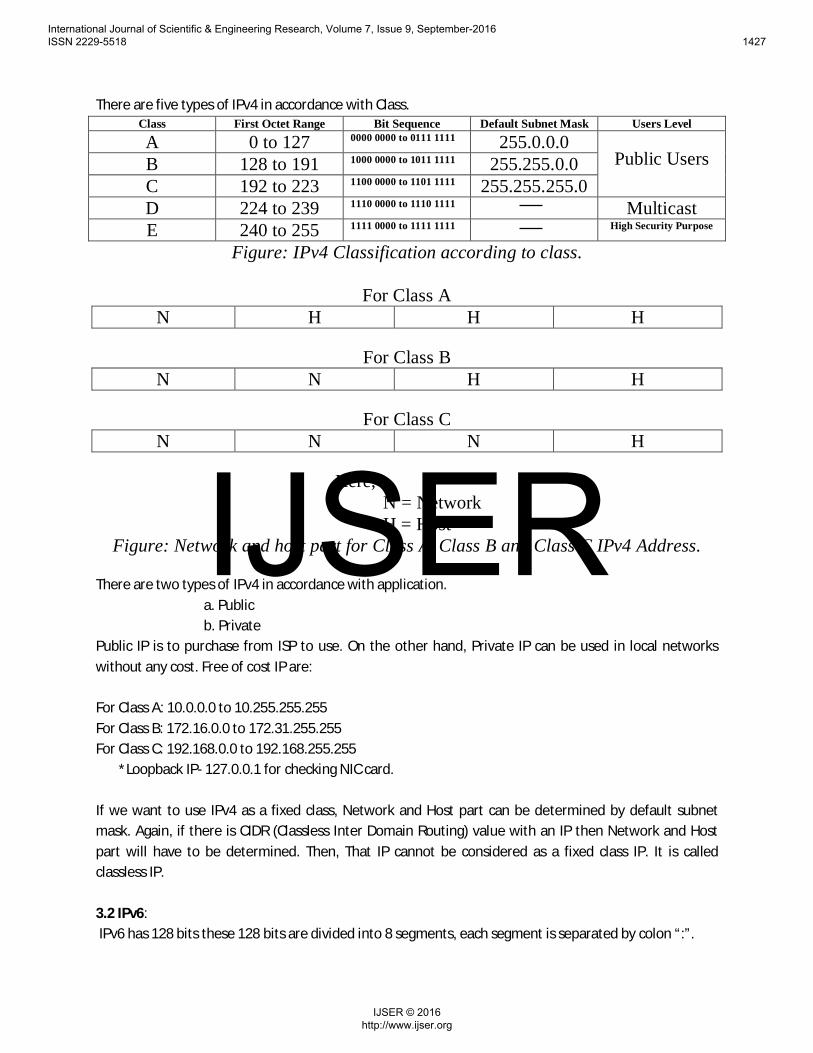
There are five types of IPv4 in accordance with Class.Class First Octet Range Bit Sequence Default Subnet Mask Users Level
A 0 to 127 0000 0000 to 0111 1111 255.0.0.0Public UsersB 128 to 191 1000 0000 to 1011 1111 255.255.0.0
C 192 to 223 1100 0000 to 1101 1111 255.255.255.0D 224 to 239 1110 0000 to 1110 1111 MulticastE 240 to 255 1111 0000 to 1111 1111 High Security Purpose
Figure: IPv4 Classification according to class.
For Class AN H H H
For Class BN N H H
For Class CN N N H
Here,N = NetworkH = Host
Figure: Network and host part for Class A, Class B and Class C IPv4 Address.
There are two types of IPv4 in accordance with application.a. Publicb. Private
Public IP is to purchase from ISP to use. On the other hand, Private IP can be used in local networkswithout any cost. Free of cost IP are:
For Class A: 10.0.0.0 to 10.255.255.255For Class B: 172.16.0.0 to 172.31.255.255For Class C: 192.168.0.0 to 192.168.255.255 *Loopback IP- 127.0.0.1 for checking NIC card.
If we want to use IPv4 as a fixed class, Network and Host part can be determined by default subnetmask. Again, if there is CIDR (Classless Inter Domain Routing) value with an IP then Network and Hostpart will have to be determined. Then, That IP cannot be considered as a fixed class IP. It is calledclassless IP.
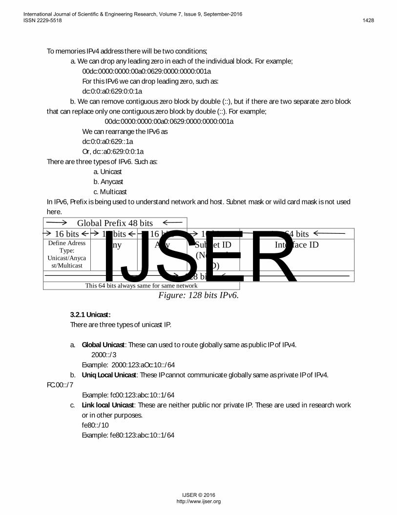
3.2 IPv6: IPv6 has 128 bits these 128 bits are divided into 8 segments, each segment is separated by colon “:”.
International Journal of Scientific & Engineering Research, Volume 7, Issue 9, September-2016 ISSN 2229-5518 1427
To memories IPv4 address there will be two conditions;a. We can drop any leading zero in each of the individual block. For example;
00dc:0000:0000:00a0:0629:0000:0000:001aFor this IPv6 we can drop leading zero, such as:dc:0:0:a0:629:0:0:1a
b. We can remove contiguous zero block by double (::), but if there are two separate zero blockthat can replace only one contiguous zero block by double (::). For example;
00dc:0000:0000:00a0:0629:0000:0000:001aWe can rearrange the IPv6 asdc:0:0:a0:629::1aOr, dc::a0:629:0:0:1a
There are three types of IPv6. Such as:a. Unicastb. Anycastc. Multicast
In IPv6, Prefix is being used to understand network and host. Subnet mask or wild card mask is not usedhere.
3.2.1 Unicast:There are three types of unicast IP.
a. Global Unicast: These can used to route globally same as public IP of IPv4. 2000::/3Example: 2000:123:aOc:10::/64
b. Uniq Local Unicast: These IP cannot communicate globally same as private IP of IPv4.FC.00::/7 Example: fc00:123:abc:10::1/64
c. Link local Unicast: These are neither public nor private IP. These are used in research workor in other purposes.fe80::/10Example: fe80:123:abc:10::1/64
International Journal of Scientific & Engineering Research, Volume 7, Issue 9, September-2016 ISSN 2229-5518 1428
3.2.2 Any cast:Any cast works as redundant system. Let, three hosts/servers are given same IP address. Therewill be no confliction, but all hosts will not work simultaneously. If one host/server is in troubleor shutdown then another one will work on automatically. Generally, these are used as back upIPs and are globally routed. 3ffe::/64 Example:
Figure: Use as a web server
In IPv4, this process is not possible where secondary server has to make using by same IP whenprimary is down then secondary will automatically up. This is a complex process.3.2.3 Multicast:In IPv6, Multicast IP is used to maintain protocol between routers to router. For example: RIP,EIGRP, and OSPF. IPs of these protocols communicates among themselves.ff00:18Example: ff00: 123: abc: 10: 1/64 *Loopback IP- ::/128 for checking NIC card.
4. The Structure of Computer Networks:The internal construction of the computer network is very complicated and also differs fromcomputer industries to industries, from the regional area to another regional area and also theprivate networks make its own private modifications. So, the actual physical construction of thenetwork is not the concern of the designers. Data transfer between two or more devices callednetworking. For networking we need two active devices and a channel.
Figure: Basic networking diagram
4.1 Why Networking:· To save time.· To save cost.· For high security.· To save energy.
Device 1/Sender
Device 2/receiver
Channel
International Journal of Scientific & Engineering Research, Volume 7, Issue 9, September-2016 ISSN 2229-5518 1429
4.2 Where Networking:· For Information Sharing.· For resource sharing.· For remote communication.· In distributed system.
4.3 For a success network system we need:· Protocols (Set of rules).· Media/ channel.· Network interface module.· Two active entity or device.
Actually there are two kind of networking group. Such as:Ø Peer-to-peer communication: Here only two device share information or data each
other. As like as Bluetooth.Ø Work group communication: There are two or more networking device communicates
each other and share information. For the connection establishment we need many kindof connection topologies. The structure of the network is sub-divided into somecriteria:
Ø TopologyØ Geographical AreaØ Data injection into the network
Ø Networking systems
4.3.1 Topology:
Topology in the field of computer network shows the common structure in which thecomputers in the network are really connected. It is not like the geographically connectionarea but the virtual connection area. The popular topologies are:
v Bus topologyv Ring topologyv Star topology
v Mesh topology
4.3.1.1 Bus Topology:Bus topology is the basic topology. In this topology computers are connected to a singleconnecting line serially. The main disadvantage of this type of connection is it is slow,
having no security for the data as all the computer in the way can intercept data packet
International Journal of Scientific & Engineering Research, Volume 7, Issue 9, September-2016 ISSN 2229-5518 1430
and it does not serve with alternative route which is required for the computers for real-time access in the network.
Figure: Bus Topology
4.3.1.2 Ring Topology:
Ring topology is like a cyclic connection. The connecting wire ends with the starting point.It is the improvement of the Bus topology as it provides bi-directional route forcommunication, choose which is the smallest path for travel to the destination computer.
But it has all the other drawback of the Bus topology.
Figure: Ring Topology
4.3.1.3 Mesh Topology: In the Mesh topology, each pair of computers in the network share a connecting wire. It
is fastest connection and reliable as none of other users can access the shared link. Butthis is costly and complex to maintain as too much wire is used.
Figure: Mesh Topology
International Journal of Scientific & Engineering Research, Volume 7, Issue 9, September-2016 ISSN 2229-5518 1431
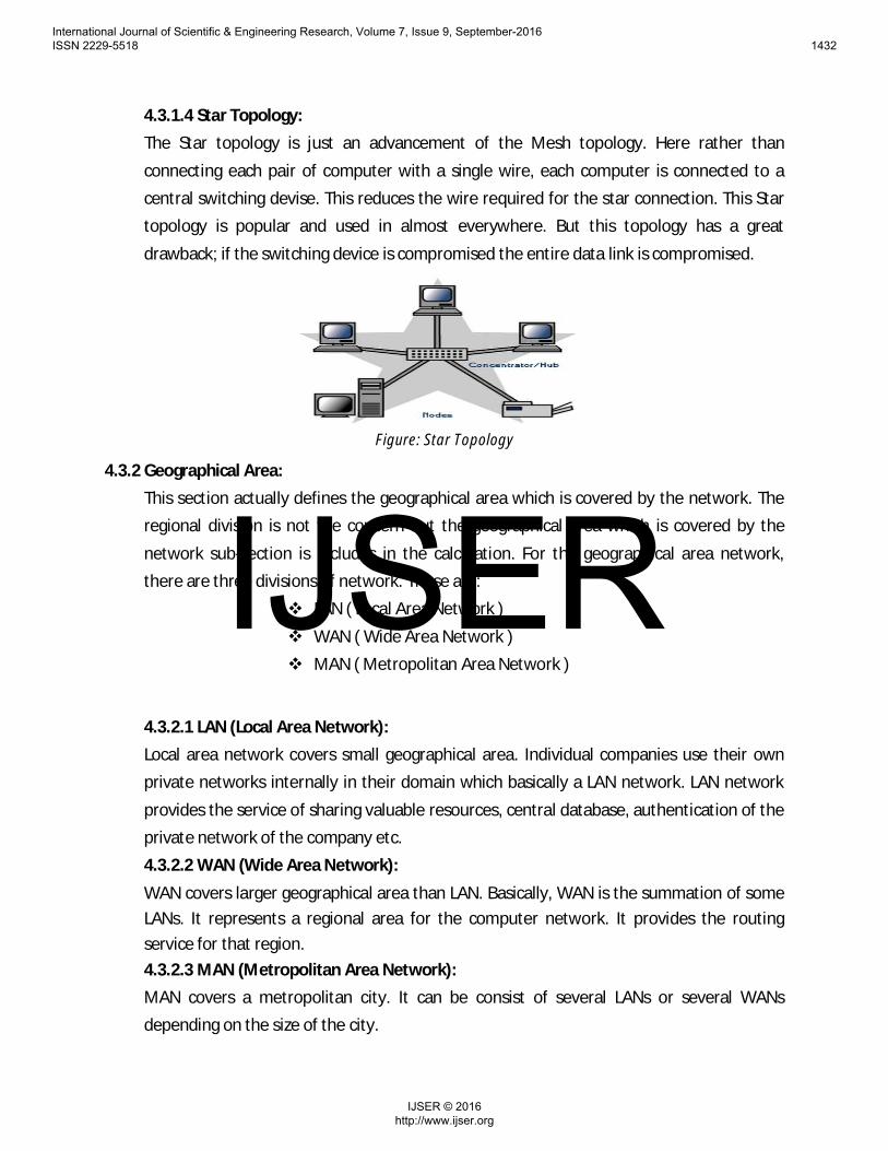
4.3.1.4 Star Topology:The Star topology is just an advancement of the Mesh topology. Here rather than
connecting each pair of computer with a single wire, each computer is connected to acentral switching devise. This reduces the wire required for the star connection. This Startopology is popular and used in almost everywhere. But this topology has a great
drawback; if the switching device is compromised the entire data link is compromised.
Figure: Star Topology
4.3.2 Geographical Area:This section actually defines the geographical area which is covered by the network. Theregional division is not the concern but the geographical area which is covered by the
network sub-section is includes in the calculation. For the geographical area network,there are three divisions of network. Those are:
v LAN ( Local Area Network )
v WAN ( Wide Area Network )v MAN ( Metropolitan Area Network )
4.3.2.1 LAN (Local Area Network):Local area network covers small geographical area. Individual companies use their ownprivate networks internally in their domain which basically a LAN network. LAN network
provides the service of sharing valuable resources, central database, authentication of theprivate network of the company etc.4.3.2.2 WAN (Wide Area Network):
WAN covers larger geographical area than LAN. Basically, WAN is the summation of someLANs. It represents a regional area for the computer network. It provides the routingservice for that region.4.3.2.3 MAN (Metropolitan Area Network):MAN covers a metropolitan city. It can be consist of several LANs or several WANsdepending on the size of the city.
International Journal of Scientific & Engineering Research, Volume 7, Issue 9, September-2016 ISSN 2229-5518 1432
This sub-section runs in the computers not in the network. It is the computational systemfor the user to network data processing or vice-versa for the transmission of theinformation. The widely used computational system for the data communication is TCP/IPprotocol model. It is a layered model and it has five layers from user level to the suitableformat of the information for transmission from the sender computer to the receivercomputer. Each layer add header of that layer for the suitable information to usethroughout the process of the communicating between senders to receivers. Those layersare (top to bottom view):
v Application layerv Transport layerv Network layer
v Data link layerv Physical layer
v
Figure: TCP/IP Model Layered Architecture.
4.3.3.1 Application Layer:The application layer is the user level layer. In this stage the computer take input of the
information which user wants to transfer from his/her computer to the receivercomputer. Ports are the software interface of the application layer to communication withthe lower layer.
4.3.3.2 Transport Layer:This is the second layer of the TCP/IP protocol model. The input of this layer is the outputof previous layer (Application layer). The main task of the transport layer is to keep track
International Journal of Scientific & Engineering Research, Volume 7, Issue 9, September-2016 ISSN 2229-5518 1433
which data packet is for which process of the receiver computer. It add transport layerheader with the information and then it is called the segment.
4.3.3.3 Network Layer:Each layer of the TCP/IP model is essential but the network layer is most important layer.Because this layer is for routing within the network. If this layer failed to work properly
the information sending via the network will not reach to the desire receiver, so thewhole process of the sharing information will be a failure. The input of this layer issegment (the output of transport layer). This layer insert network layer header. After
inserting the network layer header the segment is converted into packet and send to thelayer below it, which is data link layer. The network can be IPv4 or IPv6 version. Accordingto the/ network version the header varies. This layer adds sender address and receiver
address within the information.4.3.3.4 Data link layer:The data link layer provides flow control, error control and framing service. This layer
insert data link layer header and the packet is now converted into frame, which is nowready to inject to the network. The data link layer injects the information frame into the
physical layer.4.3.3.5 Physical layer:The physical layer transports the data packet to the receiver computer via the physical
connections of computer in the network. Depending on medium of the physical layer, thenetwork can be two types –
v Wire-connected network
v Wireless network
5.1 Network Drawback:
Computer network is the modern technique of transferring information. There are still somedrawbacks exist. Those drawbacks are:
v Routing problem
v Security over the network
Modern researchers are trying to overcome those drawbacks to make the system more reliableand more efficient. Our targeted topic is network security. To obtain this goal we implemented
cryptology over the information. Then injected the information packet to the network.
International Journal of Scientific & Engineering Research, Volume 7, Issue 9, September-2016 ISSN 2229-5518 1434
5.2Network Security:Network security is normally defined as the methods and principles adopted by the network
administrator to prevent unauthorized intermediate users to get access, misuse or modificationcomputer network and network-accessible resources. Network security involves theauthorization of users to get access in a network, which is monitored by the network
administrator. Networks can be private, such as within a company, and others which might beopen for public access. In the private network, network security provides authentication servicefor the verification of exact user to get permitted in the network. And in the public network,
network security provides authentication and data confidentiality services. The networksecurity can be improved in two sections. One is improving the authentication system andprevents the unwanted users and data packets in the network. For this department, firewall is
applied in the routers. Firewall discards all unwanted data packets that are selected by thenetwork administrator. And for the authentication service password based permission schemecan be applied. Another section of network security is to change the original data for
transmission in a way which is only known to the receiver end only. In this way, if the unwantedintermediate users anyhow get access to the network and intercept the data packet he will get
garbage information and will not understand the original information. Appling cryptography inthe information in sender end serves this service.
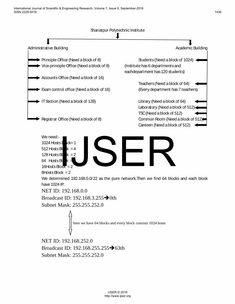
6. The Design of the Network (IPv4 Based) on Shariatpur Polytechnic Institute’s Campus:
At first we have to follow some steps to complete the networking process. Such as:
§ Figure out the network and host requirement.§ Satisfy the network and host requirement.
# Figure out network bits # Figure out host bits
§ Determined the subnet mask.§ Figure out the block size.
# Find out Net IP# Find out Broadcast IP
§ Calculate total available host IP
We have two buildings in our institute campus. One is Administrative building and the other is Academicbuilding. The chart given below describes each and every department of the Institute with the block size.
International Journal of Scientific & Engineering Research, Volume 7, Issue 9, September-2016 ISSN 2229-5518 1435
NET ID: 192.168.224.0Broadcast ID: 192.168.227.255 è56thSubnet Mask: 255.255.252.0
We have to avoide every NET ID and Broadcast ID for using as host.
7. Conclusion:Technical education is the main part of our developing nation. So it might be mandatory to know about IPaddressing and their application. This paper helps the people who want to enter this virtual word. If anyperson helped by this work then it will be our pleasure.
8. Future Work:Now IPv4 is in a critical stage thats why we try to develope a network based on IPv6 and describe theIPv6 in details.
International Journal of Scientific & Engineering Research, Volume 7, Issue 9, September-2016 ISSN 2229-5518 1440
9. Reference:[1] "IPv6 Headers", Online:http://www.cu.ipv6tf.org/literatura/chap3.pdf, chapter 3, pp. 40-55, Des 12 1997.[2] S. Deering, R. Hinden, Internet Protocol Version 6(RFC2460), 1998[3] Ipv4/Ipv6 Translation Technology, Masaki Nakajima,Nobumasu Kobayashi,2004[4] The Benefits of Using Internet Protocol Version 6 (IPV6)byAmerN.AbuAli, Ismail Ghazi Shayeb, KhaldounBatiha,Haifa YabuAliudos, Vol. 5. n. 6, pp. 583-587.[5] Patrick Grossetete, Ciprian P. Popoviciu, Fred Wettling,"Global IPv6 Strategies: From Business Analysis toOperational Planning" Online:http://media.techtarget.com/searchNetworking/downloads/IPv4_or_IPv6.pdf, 1st Edition, chapter 2, pp. 18-53, May15, 2008.[6] Charles M. Kozierok, "TCP/IP Guid A COMPREHENSIVE ,ILLUSTRATED INTERNET NTERNET PROTOCOLSREFERENCE", Online:http://nostarch.com/download/tcpip_ch25.pdf, chapter 25,pp.373-381, October 2005.[7] Hitesh Ballani, Paul Francis, Cornell University, Ithaca, NY,"Understanding IP Anycast", Online:http://pias.gforge.cis.cornell.edu/unpub/any-measure.pdf[8] B. Carpenter and K. Moore, “Connection of IPv6 Domains via IPv4Clouds,” 2001, IETF RFC 3056.[9] B. Carpenter and C. Jung, “Transmission of IPv6 over IPv4 Domainswithout Explicit Tunnels,” 1999, IETF RFC 2529.[10] G. Tsirtsis and P. Srisuresh, “Network Address Translation - ProtocolTranslation (NAT-PT),” 2000, IETF RFC 2766.[11] E. Nordmark, “Stateless IP/ICMP Translation Algorithm(SIIT),” 2000,IETF RFC 2765.[12] K. Tsuchiya, H. Higuchi, and Y. Atarashi, “Dual Stack Hosts using the”Bump-In-the-Stack” Technique (BIS),” 2000, IETF RFC 2767.[13] M. Tatipamula, P. Grossetete, and H. Esaki, “IPv6 integration andcoexistence strategies for next-generation networks,” IEEE Commun.Mag., vol. 42, no. 1, pp. 88 – 96, jan 2004.
International Journal of Scientific & Engineering Research, Volume 7, Issue 9, September-2016 ISSN 2229-5518 1441